WO2009104691A1 - Laser à fibre optique - Google Patents
Laser à fibre optique Download PDFInfo
- Publication number
- WO2009104691A1 WO2009104691A1 PCT/JP2009/052918 JP2009052918W WO2009104691A1 WO 2009104691 A1 WO2009104691 A1 WO 2009104691A1 JP 2009052918 W JP2009052918 W JP 2009052918W WO 2009104691 A1 WO2009104691 A1 WO 2009104691A1
- Authority
- WO
- WIPO (PCT)
- Prior art keywords
- optical fiber
- laser
- wavelength
- light
- refractive index
- Prior art date
- Legal status (The legal status is an assumption and is not a legal conclusion. Google has not performed a legal analysis and makes no representation as to the accuracy of the status listed.)
- Ceased
Links
Images










Classifications
-
- H—ELECTRICITY
- H01—ELECTRIC ELEMENTS
- H01S—DEVICES USING THE PROCESS OF LIGHT AMPLIFICATION BY STIMULATED EMISSION OF RADIATION [LASER] TO AMPLIFY OR GENERATE LIGHT; DEVICES USING STIMULATED EMISSION OF ELECTROMAGNETIC RADIATION IN WAVE RANGES OTHER THAN OPTICAL
- H01S3/00—Lasers, i.e. devices using stimulated emission of electromagnetic radiation in the infrared, visible or ultraviolet wave range
- H01S3/23—Arrangements of two or more lasers not provided for in groups H01S3/02 - H01S3/22, e.g. tandem arrangements of separate active media
- H01S3/2308—Amplifier arrangements, e.g. MOPA
-
- G—PHYSICS
- G02—OPTICS
- G02B—OPTICAL ELEMENTS, SYSTEMS OR APPARATUS
- G02B6/00—Light guides; Structural details of arrangements comprising light guides and other optical elements, e.g. couplings
- G02B6/02—Optical fibres with cladding with or without a coating
- G02B6/02295—Microstructured optical fibre
- G02B6/02314—Plurality of longitudinal structures extending along optical fibre axis, e.g. holes
- G02B6/02319—Plurality of longitudinal structures extending along optical fibre axis, e.g. holes characterised by core or core-cladding interface features
- G02B6/02338—Structured core, e.g. core contains more than one material, non-constant refractive index distribution in core, asymmetric or non-circular elements in core unit, multiple cores, insertions between core and clad
-
- G—PHYSICS
- G02—OPTICS
- G02B—OPTICAL ELEMENTS, SYSTEMS OR APPARATUS
- G02B6/00—Light guides; Structural details of arrangements comprising light guides and other optical elements, e.g. couplings
- G02B6/02—Optical fibres with cladding with or without a coating
- G02B6/02295—Microstructured optical fibre
- G02B6/02314—Plurality of longitudinal structures extending along optical fibre axis, e.g. holes
- G02B6/02342—Plurality of longitudinal structures extending along optical fibre axis, e.g. holes characterised by cladding features, i.e. light confining region
- G02B6/02357—Property of longitudinal structures or background material varies radially and/or azimuthally in the cladding, e.g. size, spacing, periodicity, shape, refractive index, graded index, quasiperiodic, quasicrystals
-
- G—PHYSICS
- G02—OPTICS
- G02B—OPTICAL ELEMENTS, SYSTEMS OR APPARATUS
- G02B6/00—Light guides; Structural details of arrangements comprising light guides and other optical elements, e.g. couplings
- G02B6/02—Optical fibres with cladding with or without a coating
- G02B6/02295—Microstructured optical fibre
- G02B6/02314—Plurality of longitudinal structures extending along optical fibre axis, e.g. holes
- G02B6/02342—Plurality of longitudinal structures extending along optical fibre axis, e.g. holes characterised by cladding features, i.e. light confining region
- G02B6/0238—Longitudinal structures having higher refractive index than background material, e.g. high index solid rods
-
- H—ELECTRICITY
- H01—ELECTRIC ELEMENTS
- H01S—DEVICES USING THE PROCESS OF LIGHT AMPLIFICATION BY STIMULATED EMISSION OF RADIATION [LASER] TO AMPLIFY OR GENERATE LIGHT; DEVICES USING STIMULATED EMISSION OF ELECTROMAGNETIC RADIATION IN WAVE RANGES OTHER THAN OPTICAL
- H01S3/00—Lasers, i.e. devices using stimulated emission of electromagnetic radiation in the infrared, visible or ultraviolet wave range
- H01S3/05—Construction or shape of optical resonators; Accommodation of active medium therein; Shape of active medium
- H01S3/06—Construction or shape of active medium
- H01S3/063—Waveguide lasers, i.e. whereby the dimensions of the waveguide are of the order of the light wavelength
- H01S3/067—Fibre lasers
- H01S3/06708—Constructional details of the fibre, e.g. compositions, cross-section, shape or tapering
- H01S3/06729—Peculiar transverse fibre profile
-
- H—ELECTRICITY
- H01—ELECTRIC ELEMENTS
- H01S—DEVICES USING THE PROCESS OF LIGHT AMPLIFICATION BY STIMULATED EMISSION OF RADIATION [LASER] TO AMPLIFY OR GENERATE LIGHT; DEVICES USING STIMULATED EMISSION OF ELECTROMAGNETIC RADIATION IN WAVE RANGES OTHER THAN OPTICAL
- H01S3/00—Lasers, i.e. devices using stimulated emission of electromagnetic radiation in the infrared, visible or ultraviolet wave range
- H01S3/05—Construction or shape of optical resonators; Accommodation of active medium therein; Shape of active medium
- H01S3/06—Construction or shape of active medium
- H01S3/063—Waveguide lasers, i.e. whereby the dimensions of the waveguide are of the order of the light wavelength
- H01S3/067—Fibre lasers
- H01S3/06708—Constructional details of the fibre, e.g. compositions, cross-section, shape or tapering
- H01S3/06729—Peculiar transverse fibre profile
- H01S3/06741—Photonic crystal fibre, i.e. the fibre having a photonic bandgap
-
- H—ELECTRICITY
- H01—ELECTRIC ELEMENTS
- H01S—DEVICES USING THE PROCESS OF LIGHT AMPLIFICATION BY STIMULATED EMISSION OF RADIATION [LASER] TO AMPLIFY OR GENERATE LIGHT; DEVICES USING STIMULATED EMISSION OF ELECTROMAGNETIC RADIATION IN WAVE RANGES OTHER THAN OPTICAL
- H01S3/00—Lasers, i.e. devices using stimulated emission of electromagnetic radiation in the infrared, visible or ultraviolet wave range
- H01S3/05—Construction or shape of optical resonators; Accommodation of active medium therein; Shape of active medium
- H01S3/06—Construction or shape of active medium
- H01S3/063—Waveguide lasers, i.e. whereby the dimensions of the waveguide are of the order of the light wavelength
- H01S3/067—Fibre lasers
- H01S3/06754—Fibre amplifiers
-
- H—ELECTRICITY
- H01—ELECTRIC ELEMENTS
- H01S—DEVICES USING THE PROCESS OF LIGHT AMPLIFICATION BY STIMULATED EMISSION OF RADIATION [LASER] TO AMPLIFY OR GENERATE LIGHT; DEVICES USING STIMULATED EMISSION OF ELECTROMAGNETIC RADIATION IN WAVE RANGES OTHER THAN OPTICAL
- H01S3/00—Lasers, i.e. devices using stimulated emission of electromagnetic radiation in the infrared, visible or ultraviolet wave range
- H01S3/05—Construction or shape of optical resonators; Accommodation of active medium therein; Shape of active medium
- H01S3/06—Construction or shape of active medium
- H01S3/063—Waveguide lasers, i.e. whereby the dimensions of the waveguide are of the order of the light wavelength
- H01S3/067—Fibre lasers
- H01S3/06791—Fibre ring lasers
-
- H—ELECTRICITY
- H01—ELECTRIC ELEMENTS
- H01S—DEVICES USING THE PROCESS OF LIGHT AMPLIFICATION BY STIMULATED EMISSION OF RADIATION [LASER] TO AMPLIFY OR GENERATE LIGHT; DEVICES USING STIMULATED EMISSION OF ELECTROMAGNETIC RADIATION IN WAVE RANGES OTHER THAN OPTICAL
- H01S3/00—Lasers, i.e. devices using stimulated emission of electromagnetic radiation in the infrared, visible or ultraviolet wave range
- H01S3/09—Processes or apparatus for excitation, e.g. pumping
- H01S3/091—Processes or apparatus for excitation, e.g. pumping using optical pumping
- H01S3/094—Processes or apparatus for excitation, e.g. pumping using optical pumping by coherent light
- H01S3/09408—Pump redundancy
Definitions
- the present invention relates to an optical fiber laser, and more particularly to an optical fiber laser in which parasitic oscillation is suppressed by using a photonic band gap fiber adjusted so as to be a photonic band gap region only in a signal wavelength region.
- optical fiber laser having an output exceeding kW has been developed.
- Such an optical fiber laser having a high output is used in various fields such as a processing machine, a medical device, and a measuring instrument.
- optical fiber lasers have excellent light condensing performance and can produce very small beam spots with high power density. Therefore, precision machining is possible.
- the processing using this optical fiber laser is a non-contact processing, and if the laser beam can be absorbed, it can be processed into a hard substance. Laser applications are expanding rapidly.
- FIG. 14 shows a schematic diagram of a typical high-power optical fiber laser called the MOPA system.
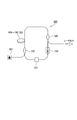
- the MOPA system has a configuration in which a power amplifier (hereinafter also referred to as PA) 200 is connected to a subsequent stage of a master oscillator (hereinafter also referred to as MO) 100.
- PA power amplifier
- MO master oscillator
- PAs 200 are connected in multiple stages so that a desired output can be obtained.
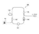
- FIG. 15 shows a typical configuration diagram of this fiber ring laser.
- the fiber ring laser 100 includes a pumping light source 101; a WDM coupler 102 that combines pumping light and laser light; a rare earth-doped optical fiber 103 that is a gain medium; an isolator 104; an optical switch element 107; and an output coupler 105.
- Excitation light emitted from the excitation light source 101 is incident on the rare earth-doped optical fiber 103 via the WDM coupler 102.
- the excitation light incident on the rare earth doped optical fiber 103 is absorbed by the rare earth ions added to the core of the rare earth doped optical fiber and excites the rare earth ions.
- the excited rare earth ions emit spontaneous emission light having a specific wavelength. This spontaneously emitted light propagates through the rare earth-doped optical fiber 103 while being amplified, and is output as ASE (Amplified Spontaneous Emission).
- the WDM coupler 102, the rare earth-doped optical fiber 103, the isolator 104, the output coupler 105, and the optical switch element 107 are connected in a ring shape. Therefore, the ASE passes through these parts and goes around, and is amplified again by the rare earth-doped optical fiber 103. After the ASE is sufficiently amplified, the laser oscillates, and a part thereof is output as laser light through the output coupler 105. At this time, if the optical switch element 107 is operated so as to periodically repeat a low-loss state and a high-loss state, pulses are oscillated and a pulsed laser output is obtained.
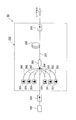
- FIG. 16 shows the configuration of a MOPA optical fiber laser.
- the laser beam output from the MO 100 is incident on the PA 200 via the interstage isolator 316, amplified by the PA 200, and output.
- the PA 200 includes a plurality of excitation light sources 201, an optical coupler 203, a rare earth-doped optical fiber (rare earth-doped double clad fiber) 205, and an isolator 206.
- the same pumping light source 201, rare earth-doped optical fiber 205, and isolator 206 as those used in the MO 100 can be applied.
- As the optical coupler 203 for example, an optical coupler as described in Patent Document 2 is used.
- This optical coupler 203 has a plurality of pumping ports 202 made of a multimode optical fiber and a signal port 204 made of one single mode fiber, which are formed by melting and extending them together.
- One exit port 207 is provided.
- Laser light emitted from the MO 100 is incident from the signal port 204 and is emitted to the core of the rare earth-doped double clad fiber 205 via the optical coupler 203.
- the optical coupler 203 is connected to a pumping port 202 to which a plurality of pumping light sources 201 are connected. The pumping light emitted from each pumping light source 201 is incident on the first cladding of the rare earth-doped double cladding fiber 205 via the optical coupler 203.
- the excitation light incident on the first cladding is absorbed by the rare earth ions added to the core to form an inversion distribution, and stimulated emission occurs. By this stimulated emission, the laser light propagating in the core is amplified and output through the isolator 206.
- the rare earth-doped double clad fiber 205 of the PA 200 is pumped by the pumping light emitted from the pumping light source 201 in a state where the signal light from the MO 100 is not incident, and is inverted.
- the distribution rate is reached, parasitic oscillation occurs and a pulse with a very high spire value is generated.
- the inversion distribution ratio at which parasitic oscillation occurs is determined by the reflectivity between the incident side and the emission side of the rare earth-doped double clad fiber 205.
- a pulse with a very high spire value is emitted from the rare earth-doped double clad fiber 205 toward the optical coupler 203 due to parasitic oscillation.
- the core of the rare earth-doped double clad fiber 205 is damaged by the pulse having a very high spire value, or the pulse reaches the excitation light source 201 or the MO 100 and is damaged.
- the PA 200 outputs from the outside. The reflected light may induce parasitic oscillation.
- the excitation light source 201 of the PA 200 emits excitation light between pulses
- the rare earth-doped double clad fiber 205 is in an excited state. Therefore, ASE is emitted from both ends of the rare earth-doped double clad fiber 205.
- the workpiece is irradiated with ASE from the optical fiber laser. At this time, depending on the surface state of the workpiece, the reflected light reflected by the surface of the workpiece may be incident on the optical fiber laser again.
- this reflected light becomes a seed and oscillation occurs, and a pulse having a very high spire value is emitted from the rare earth-doped double clad fiber 205 toward the optical coupler 203. Then, this pulse reaches the excitation light source 201 and the MO100, and there is a problem that they are damaged.
- the parasitic oscillation occurs, a high inversion distribution rate cannot be realized, and the energy of the pulse that can be output from the PA 200 is limited.
- an isolator is inserted at both ends of the rare earth-doped optical fiber to suppress the reflectance and suppress the parasitic oscillation. Furthermore, by providing a short wavelength pass filter at the exit end of the excitation light source, the ASE emitted from the rare earth-doped optical fiber is prevented from being reflected by the pump laser and entering the rare earth-doped optical fiber again. That is, the optical fiber laser described in Patent Document 3 suppresses parasitic oscillation by suppressing the reflectance on the incident side and the emission side of the rare earth-doped optical fiber as much as possible.
- the optical fiber amplifier is divided into two stages, and an isolator is provided between the stages.
- parasitic oscillation is suppressed by suppressing the gain low.
- the optical fiber laser described in Patent Document 4 does not lead to parasitic oscillation although ASE amplification occurs.
- a resonator is configured by providing fiber Bragg gratings (hereinafter sometimes referred to as FBGs) at both ends of a rare earth-doped double clad fiber, and a multimode is further provided in one FBG. Fiber is connected. Excitation light from the excitation light source is incident on the rare earth-doped double clad fiber through the multimode fiber.
- the core diameter of the multimode fiber is larger than the core diameter of the rare earth-doped double clad fiber.
- the ASE having an unnecessary wavelength that is incident on the multimode fiber without being reflected by the FBG has a low rate of recombination with the core of the rare earth-doped double clad fiber, and parasitic oscillation is suppressed. Even if the parasitic oscillation occurs, the generated pulse is once incident on the multimode fiber. Therefore, even if the ASE is condensed on the excitation light source through the lens, the spot diameter is increased, and thus the excitation light source is hardly damaged.
- the limit of the reflectance is practically limited to about 0.001%. Therefore, in a relatively high-power optical fiber laser that outputs several tens of watts or more, no matter how much reflection is suppressed, this slight reflection or Rayleigh scattering in the fiber becomes a seed, and parasitic oscillation occurs. There is a risk that. Further, with respect to externally reflected light (reflected light on the workpiece surface) generated after laser emission, the intensity of the reflected light is attenuated by the isolator, but cannot be completely cut. Therefore, there is a possibility that parasitic oscillation may be induced by using the slightly remaining reflected light as a seed.
- the present invention has been made in view of the above circumstances, and an object of the present invention is to provide an optical fiber laser in which parasitic oscillation is suppressed and a high-energy pulse can be stably emitted.
- An optical fiber laser of the present invention includes a master oscillator that is a laser oscillator that generates seed light, and an optical amplifier that is connected to a subsequent stage of the master oscillator and amplifies and outputs laser light emitted from the master oscillator.
- An optical fiber laser comprising: a plurality of pumping light sources; and a plurality of pumping light sources, each of which is connected to the plurality of pumping light sources, and the pumping light emitted from the pumping light source is incident thereon.
- An excitation port a signal port to which the laser beam emitted from the master oscillator is incident, an emission beam that emits the excitation light incident from the excitation port and the laser beam incident from the signal port.
- An optical coupler having a port; and an optical fiber connected to the output port; It is a gap fiber; the optical fiber, wavelength horizontal axis, vertical axis in the graph showing the loss, the photonic band gap region has a narrow loss wavelength characteristic than the gain wavelength band.
- the optical fiber is provided with a core portion made of a solid material doped with a rare earth element; a first cladding provided around the core portion; and provided in the vicinity of the core portion of the first cladding; And a periodic structure portion in which a number of high refractive index portions having a higher refractive index than the first cladding are arranged in a periodic structure.
- the maximum relative refractive index difference of the high refractive index portion with respect to the first cladding is preferably 2% to 3%.
- the electric field distribution of light having a wavelength in the photonic band gap region is higher in the core portion than the periodic structure portion; the electric field distribution of light in a wavelength other than the photonic band gap region is the period
- the structure is higher than the core.
- the high refractive index portion preferably contains at least germanium.
- An optical fiber laser of the present invention includes a master oscillator that is a laser oscillator that generates seed light, and an optical amplifier that is connected to a subsequent stage of the master oscillator and amplifies and outputs laser light emitted from the master oscillator.
- An optical fiber laser comprising a power amplifier, wherein the master oscillator is connected to the excitation light source, and a WDM coupler that combines the excitation light from the excitation light source and the laser light;
- An optical fiber connected to the WDM coupler, an output coupler connected to the optical fiber, and an isolator; the WDM coupler, the optical fiber, the output coupler, and the isolator are sequentially ring-shaped.
- the optical fiber has a photonic bar in a graph in which the horizontal axis indicates the wavelength and the vertical axis indicates the loss amount. -Gap region has a narrow loss wavelength characteristic than the gain wavelength band.
- An optical fiber laser of the present invention includes a master oscillator that is a laser oscillator that generates seed light, and an optical amplifier that is connected to a subsequent stage of the master oscillator and amplifies and outputs laser light emitted from the master oscillator.
- the power amplifier is the power amplifier described in (1) above; the master oscillator is the master oscillator described in (6) above.
- the optical fiber laser described in (1) above According to the optical fiber laser described in (1) above, ASE at an unnecessary wavelength that causes parasitic oscillation can be efficiently removed. Therefore, it is possible to lengthen the time until parasitic oscillation occurs. Therefore, more energy can be stored than the conventional optical fiber laser. As a result, when the pulsed light is amplified, high gain amplification can be performed, and high energy pulse output that cannot be output by a conventional optical fiber laser becomes possible. Further, even in the condition where the parasitic oscillation has conventionally occurred, the optical fiber laser of the present invention does not generate the parasitic oscillation. Therefore, damage caused to each component of the optical fiber laser by this parasitic oscillation can be suppressed.
- optical fiber laser of the present invention unnecessary light is removed in a wavelength distribution, so that the unnecessary light does not become high intensity. Therefore, the unnecessary light has little influence on the optical component, and cooling is easy. Therefore, an optical fiber laser that can be used stably over a long period of time can be provided. In addition, similar effects can be obtained with the optical fiber laser described in (6) above.
- FIG. 1A is a diagram schematically showing an optical fiber laser according to the first embodiment of the present invention.
- FIG. 1B is a diagram showing loss wavelength characteristics of the optical fiber used in the optical fiber laser of the same embodiment.
- FIG. 2A is a cross-sectional view schematically showing an optical fiber used in the optical fiber laser of the embodiment.
- FIG. 2B is a diagram showing a refractive index profile of the optical fiber used in the optical fiber laser of the same embodiment.
- FIG. 2C is a diagram schematically showing the electric field distribution of the optical fiber used in the optical fiber laser of the embodiment.
- FIG. 3A is a cross-sectional view schematically showing an optical fiber used in an optical fiber laser according to the second embodiment of the present invention.
- FIG. 3B is a diagram showing a refractive index profile of the optical fiber used in the optical fiber laser of the embodiment.
- FIG. 3C is a diagram schematically showing an electric field distribution of the optical fiber used in the optical fiber laser of the embodiment.
- FIG. 4A is a cross-sectional view schematically showing an optical fiber used in an optical fiber laser according to the third embodiment of the present invention.
- FIG. 4B is a diagram showing a refractive index profile of the optical fiber used in the optical fiber laser of the embodiment.
- FIG. 4C is a diagram schematically showing an electric field distribution of the optical fiber used in the optical fiber laser of the embodiment.
- FIG. 5A is a cross-sectional view schematically showing an optical fiber used in an optical fiber laser according to the fourth embodiment of the present invention.
- FIG. 5B is a diagram showing a refractive index profile in the A-A ′ direction of the optical fiber used in the optical fiber laser of the same embodiment.
- FIG. 5C is a diagram schematically showing the electric field distribution in the B-B ′ direction of the optical fiber used in the optical fiber laser of the embodiment.
- FIG. 5D is a diagram showing a refractive index profile in the A-A ′ direction of the optical fiber used in the optical fiber laser of the embodiment.
- FIG. 5E is a diagram schematically showing the electric field distribution in the B-B ′ direction of the optical fiber used in the optical fiber laser of the embodiment.
- FIG. 6A is an electron micrograph of a cross section of the optical fiber used in the optical fiber laser according to the fifth embodiment of the present invention.
- FIG. 6B is a diagram showing a refractive index profile of the optical fiber used in the optical fiber laser of the same embodiment.
- FIG. 6C is a diagram schematically showing the electric field distribution in the X-axis direction of the optical fiber used in the optical fiber laser of the embodiment.
- FIG. 6D is a diagram schematically showing an electric field distribution in the Y-axis direction of the optical fiber used in the optical fiber laser of the embodiment.
- FIG. 7 is a diagram schematically showing an optical fiber laser according to the sixth embodiment of the present invention.
- FIG. 8 is a diagram observing the time from when the excitation light is input to when the parasitic oscillation occurs using the optical fiber laser of Example 1.
- FIG. 9 is a diagram observing the time from when the excitation light is input to when the parasitic oscillation occurs using the optical fiber laser of the second embodiment.
- FIG. 10 is a diagram observing the time from when the excitation light is input until the parasitic oscillation occurs using the optical fiber laser of the comparative example.
- FIG. 11 is a diagram schematically showing an apparatus used for measuring a transmission spectrum of the optical fiber used in Example 4.
- FIG. 12 is a diagram showing a transmission spectrum of the optical fiber used in Example 4.
- FIG. 13A is a diagram when the ASE spectrum of the optical fiber laser of Example 4 is measured.
- FIG. 13B is a diagram when the ASE spectrum of the optical fiber laser of Example 4 is measured.
- FIG. 14 is a schematic view of a typical optical fiber laser of the MOPA system.
- FIG. 15 is a diagram schematically showing a general MO.
- FIG. 16 is a diagram schematically showing a general PA and an optical fiber laser.
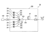
- FIG. 1A is a configuration diagram schematically showing an optical fiber laser 50 according to a first embodiment of the present invention.
- FIG. 1B shows the loss wavelength characteristics of the optical fiber 10 used in the optical fiber laser 50 of the present embodiment.
- the optical fiber laser of the present embodiment is connected to a master oscillator (hereinafter also referred to as MO) 100 of a laser oscillator that generates seed light and a subsequent stage of this MO, similarly to the optical fiber laser shown in FIG.
- MO master oscillator
- PA power amplifier
- the MO 100 for example, a fiber ring laser 100 shown in FIG. 15 can be used.
- the output side of the MO 100 is connected to the PA 200 via an interstage isolator 316.
- the PA 200 includes a plurality of excitation light sources 201; an excitation port 202 that is connected to each of the plurality of excitation light sources 201 and into which the excitation light emitted from the excitation light source 201 is incident; and a laser beam emitted from the master oscillator 100 And an optical coupler 203 having an output port 205 for emitting each pump light incident from the pump port 202 and laser light incident from the signal port 204;
- the optical fiber 10 connected to 205 is schematically configured. Laser light emitted from the MO 100 enters the PA 200 from the signal port 204 and enters the core of the optical fiber 10 via the optical coupler 203.
- the optical fiber 10 includes a core and a clad surrounding the core. Rare earth ions are added to the core.
- the excitation light emitted from each excitation light source 201 is incident on the first cladding of the optical fiber 10 via the optical coupler 203.
- the excitation light incident on the first cladding of the optical fiber 10 is absorbed by the rare earth ions added to the core to form an inversion distribution, and stimulated emission occurs.
- This stimulated emission amplifies the laser beam propagating in the core.
- This amplified laser beam is output via the isolator 206. That is, the laser beam output from the MO 100 is incident on the PA 200 via the interstage isolator 316, amplified by the PA 200, and output. Details will be described below.
- optical coupler 203 for example, a conventionally known optical coupler as disclosed in Patent Document 2 is used, and a plurality of pumping ports 202 made of a multimode optical fiber and a signal port made of one single mode fiber. 204 on one side. On the other side of the optical coupler 203, there is an emission port 205 that emits each excitation light incident from the excitation port 202 and laser light incident from the signal port 204.
- a laser diode (LD) or the like is preferably used, but is not limited thereto.
- the optical fiber 10 is a photonic bandgap fiber and has the loss characteristics shown in FIG. 1B.
- the horizontal axis of the graph in FIG. 1B indicates the wavelength of light, and the vertical axis indicates the amount of light loss.
- the photonic band gap exists within the gain wavelength band of optical amplification by rare earth ions added to the core. Furthermore, this photonic band gap is a narrower wavelength band than the gain wavelength band. In addition to this wavelength band relationship, the structure described later is determined so that the photonic band gap includes the oscillation wavelength of the optical fiber laser 50.
- the photonic band gap is formed only in the oscillation wavelength band to be guided among the spontaneous emission light over a wide wavelength band generated when the rare earth ions added to the core part are excited. For this reason, the light of the oscillation wavelength is confined and propagated in the core portion of the optical fiber 10, and the spontaneous emission light in the wavelength band other than the oscillation wavelength band is emitted to the clad without being confined in the core portion. That is, since spontaneous emission light other than the oscillation wavelength band that becomes the seed of parasitic oscillation is emitted from the core portion to the cladding, parasitic oscillation can be suppressed. In particular, parasitic oscillation is likely to occur at a wavelength at which the gain of the rare earth-doped optical fiber is maximized.
- the optical fiber 10A (10) used in the optical fiber laser 50 of the present embodiment has a cross-sectional structure shown in FIG. 2A, for example.
- the optical fiber 10A includes a core portion 11 made of a solid material doped with a rare earth element; a first cladding 13 provided around the core portion 11; and a vicinity of the core portion 11 of the first cladding 13.
- crud 13 is comprised roughly from the periodic structure part 12 arrange
- a fluorine-based ultraviolet curable resin layer having a negative relative refractive index difference with respect to pure quartz may be provided on the outer periphery of the first cladding 13.
- the optical fiber 10A has a completely solid structure with no holes. Therefore, when the optical fiber 10A of the present embodiment is fusion-spliced with another optical fiber, the holes are not crushed and the structure is not changed. Therefore, fusion splicing can be performed with low loss.
- Each part of the core part 11, the periodic structure part 12, and the first cladding 13 of the optical fiber 10A is made of pure silica glass or quartz glass obtained by adding a refractive index adjusting dopant such as fluorine or germanium. It is composed of In the optical fiber 10 of this embodiment, the material of each part is not limited only to this illustration.
- the core part 11 is formed by adding rare earth ions to pure quartz.
- the refractive index of the core 11 is preferably the same as that of pure quartz.
- Examples of rare earth ions to be added include ytterbium (Yb), erbium (Er), thulium (Tm), neodymium (Nd), praseodymium (Pr), etc., and these may be used alone or May be mixed in a desired ratio.
- high refractive index portions 14 In the vicinity of the core portion 11 of the first cladding 13, a large number of high refractive index regions (high refractive index portions 14) having a small circular cross section to which germanium (Ge) or the like is added are arranged.
- the high refractive index portions 14 are arranged in a triangular lattice-like periodic structure to form the periodic structure portion 12.
- the triangular lattice shape means the first high refractive index portion 14a, the second high refractive index portion 14b adjacent to the first high refractive index portion 14a, and the first high refractive index portion.
- 14a and the third high refractive index portion 14c adjacent to the second high refractive index portion 14b form an equilateral triangle.
- a photonic band having a desired wavelength band can be formed by adjusting the diameter and period of the high refractive index portion 14, the interval between the high refractive index portions 14, and the relative refractive index difference with respect to pure quartz glass.
- the diameter of the high refractive index portion 14 is 3 ⁇ m to 5 ⁇ m
- the interval between the high refractive index portions 14 is 5 ⁇ m to 10 ⁇ m
- the period of the high refractive index portion 14 is 3 to 6 layers.
- the maximum relative refractive index difference with respect to the first cladding is 2% to 3%.
- the region of the first cladding 13 where the periodic structure portion 12 is disposed occupies a larger proportion than the region of the first cladding 15 where the periodic structure portion 12 is not disposed.
- the core portion 11 having the same refractive index as that of pure quartz is arranged at the center, and Ge or the like is added to the periphery thereof to refract more than the core portion 11.
- the periodic structure part 12 with a high rate is arranged. Therefore, the refractive index profile of the optical fiber 10A is shown in FIG. 2B. As shown in FIG. 2B, the refractive indexes of the core portion 11 and the first cladding 13 are equal, and the refractive index of the periodic structure portion 12 (the refractive index of each high refractive index portion 14) is the same as that of the core portion 11 and the first cladding portion 13. The refractive index is higher than that of the first cladding 13.
- the light in the photonic band gap wavelength region is confined in the low refractive index region, that is, the core portion 11.
- the light in the wavelength region of the photonic band gap has an electric field concentrated on the core portion 11 and guided through the core portion 11 as shown in the upper part of FIG. 2C. That is, for light in the wavelength range of the photonic band gap, the low refractive index region functions as a core portion, and the high refractive index region (periodic structure portion 12 including the high refractive index portion 14) functions as a cladding.
- the optical fiber laser 50 of the present embodiment by using the optical fiber 10A, ASE at an unnecessary wavelength, which causes parasitic oscillation, can be efficiently removed, and the time until parasitic oscillation occurs is reduced. Can be long. Therefore, more energy can be stored than the conventional optical fiber laser. Therefore, when amplifying pulsed light, high gain amplification can be performed, and high energy pulse output that cannot be output by a conventional optical fiber laser becomes possible.
- parasitic oscillation does not occur even under conditions where parasitic oscillation has conventionally occurred. Therefore, it is possible to suppress damage that occurs in each component of the fibre laser. Furthermore, since unnecessary light is removed in a wavelength distribution, the unnecessary light does not become high intensity. Therefore, the unnecessary light has little influence on the optical component, and cooling of each component constituting the optical fiber laser is facilitated. Therefore, an optical fiber laser that can be used stably over a long period of time is obtained.
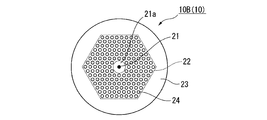
- FIG. 3A is a cross-sectional view schematically showing an optical fiber 10B (10) mounted on the optical fiber laser according to the second embodiment.
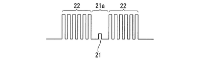
- FIG. 3B is a diagram showing a refractive index profile of the optical fiber 10B used in the present embodiment.
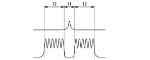
- FIG. 3C is a diagram showing an electric field distribution of the optical fiber 10B used in the present embodiment.
- the optical fiber laser of this embodiment is different from the optical fiber laser of the first embodiment in that it has a cross section shown in FIG. 3A and has a refractive index profile shown in FIG. 3B and an electric field distribution shown in FIG. 3C. This is a point using the fiber 10B.
- the refractive index profile of the optical fiber 10B according to the present embodiment also includes a high refractive index portion (core portion 21) in the region 21a.
- light having a wavelength in the photonic band gap region is a region having a high refractive index (periodic structure) in which the high refractive index portion 24 is disposed, as in the optical fiber 10A of the first embodiment. Part 22) cannot be guided. For this reason, the light is guided inside the periodic structure portion 22.
- a core portion 21 having a refractive index higher than that of pure quartz is formed at the center. Therefore, as shown in the upper part of FIG. 3C, the light having a wavelength in the photonic band gap region concentrates more strongly on the core portion 21 than the optical fiber 10 ⁇ / b> A used in the first embodiment.
- the optical fiber 10B of the present embodiment is formed by rotating an optical fiber preform during spinning. Therefore, the periodic structure portion 22 is twisted in a spiral shape in the length direction of the fiber. Therefore, the optical fiber preform is substantially bent in the longitudinal direction. Therefore, loss of light occurs in the optical fiber 10B due to macro vent or micro vent. In the optical fiber 10B used in the present embodiment, the loss of light gives loss to light in a wavelength region other than the photonic band gap guided through the core portion 21, and removes this light. On the other hand, since the core part 21 is in the center of the optical fiber 10 ⁇ / b> B, twist does not appear in the shape of the core part 21.
- the helical pitch may be adjusted as appropriate so as to give a loss to light in a desired wavelength range.
- the optical fiber 10B As described above, by using the optical fiber 10B, it is possible to effectively remove light having a wavelength other than the photonic band gap region. Therefore, in the optical fiber laser using this optical fiber 10B, the ASE at the unnecessary wavelength that causes the parasitic oscillation is removed, and the time until the parasitic oscillation occurs can be lengthened. Therefore, the same effect as the optical fiber laser 50 of the first embodiment described above can be obtained.
- the refractive index of the core portion 21 is higher than that of the optical fiber 10A of the first embodiment. Therefore, the electric field of light having a wavelength in the photonic band gap region is stronger in the core portion 21 than in the optical fiber 10A of the first embodiment. As a result, in the optical fiber laser of the present embodiment, the laser light propagating in the core portion 21 can be amplified more greatly, and higher-energy pulse output is possible than in the optical fiber laser of the first embodiment.
- the optical fiber 10B used in the present embodiment loss was given to light in a wavelength region other than the photonic band gap guided through the core portion 21 by the macro vent or the micro vent, but in the periodic structure portion 22, An additive that absorbs or scatters light having a fluorescence wavelength of Yb may be added to give loss to light in a wavelength region other than the photonic band gap. Further, if the return loss on the incident side and the outgoing side of the optical fiber 10B is larger than the gain received by the optical fiber 10B, parasitic oscillation can be suppressed. The light guided through the optical fiber 10B undergoes two losses when emitted from the optical fiber 10B and when incident. Therefore, when the light emitted from the optical fiber 10B or incident, the loss received by the light of the wavelength other than the photonic band gap region is larger than half of the gain received when guiding the optical fiber 10B, Parasitic oscillation can be suppressed.
- FIG. 4A is a cross-sectional view schematically showing an optical fiber 10C (10) mounted on the optical fiber laser according to the third embodiment.
- FIG. 4B is a diagram showing a refractive index profile of the optical fiber 10C used in the present embodiment.
- FIG. 4C is a diagram showing an electric field distribution of the optical fiber 10C used in the present embodiment.
- the optical fiber laser of this embodiment is different from the optical fiber laser of the first embodiment in that it has a cross section shown in FIG. 4A and has a refractive index profile shown in FIG. 4B and an electric field distribution shown in FIG. 4C. This is a point using the fiber 10C.
- the first layer and the second layer (near the core) inside the periodic structure portion 12 of the first embodiment are eliminated, and a region 31a made of pure quartz is formed. Is formed.
- this region 31a Al, Ge or the like is doped in addition to Yb, and a core portion 31 having a refractive index higher by about 0.1% to 0.5% than that of surrounding pure quartz is formed. Therefore, as shown in FIG. 4B, the refractive index profile of the optical fiber 10C of the present embodiment also includes a portion having a high refractive index in the core portion 31 of the region 31a.
- the intervals between the high refractive index portions 34 are narrowed by about 10% to 20%, and are concentrated near the core portion 31.
- the diameter of the high refractive index portion 34 is about 30% to 40% larger than that of the first embodiment.
- the relative refractive index difference between the high refractive index portion 34 and pure silica glass is the same as that of the optical fibers of the first and second embodiments.
- the number of layers of the periodic structure portion 34 of the optical fiber 10 of the present embodiment is smaller than that of the first embodiment, for example, about three layers. Since the diameter of the first clad 33 is the same as that of the first embodiment, the region 35 where the periodic structure portion 32 of the first clad 33 is not disposed is wider than that of the first embodiment.
- a fluorine-based ultraviolet curable resin layer 36 having a negative relative refractive index difference with respect to pure quartz (for example, about ⁇ 5%) is disposed.
- the first clad 33 made of pure silica glass forms the second core
- the fluorine-based ultraviolet curable resin 36 forms the second clad, and is a double-mode guided multimode. It has a clad structure.
- the refractive index profile and electric field distribution are the same as in the second embodiment, and are as shown in FIGS. 4B and 4C, respectively. That is, as shown in the upper part of FIG. 4C, the light having a wavelength in the photonic band gap region concentrates more strongly on the core portion 31 than the optical fiber 10A used in the first embodiment. As shown in the lower part of FIG. 4C, light having a wavelength other than the photonic band gap region has a slight electric field in the core portion 31 in addition to the periodic structure portion 32 of the optical fiber 10C. Waveguide becomes possible. Similarly to the optical fiber 10B used in the second embodiment, light other than the photonic band gap wavelength region is removed from the optical fiber 10C used in the present embodiment by the macro vent or the micro vent.
- the core portion 31 is also similar to the optical fiber 10B of the second embodiment, and light having a wavelength in the photonic band gap region does not cause light loss due to the above macro vent or micro vent, and the core portion 11 Has not been removed from.
- the optical fiber 10C As described above, by using the optical fiber 10C, it is possible to effectively remove light having a wavelength other than the photonic band gap region. Therefore, in the optical fiber laser using this optical fiber 10C, the ASE at the unnecessary wavelength that causes the parasitic oscillation is removed, and the time until the parasitic oscillation occurs can be lengthened.
- the light of the second embodiment described above The same effect as the fiber laser can be obtained.
- FIG. 5A is a cross-sectional view schematically showing an optical fiber 10D (10) mounted on an optical fiber laser according to the fourth embodiment.
- FIG. 5B is a refractive index profile in the AA ′ direction of the optical fiber 10D.
- FIG. 5C is a refractive index profile in the BB ′ direction of the optical fiber 10D.
- FIG. 5D shows an electric field distribution in the AA ′ direction of the optical fiber 10D.
- FIG. 5E shows an electric field distribution in the BB ′ direction of the optical fiber 10D.
- the optical fiber laser of the present embodiment is different from the optical fiber laser of the first embodiment in that it has the cross section shown in FIG. 5A and the refractive index profile shown in FIGS. 5B and 5C and the electric field distribution shown in FIGS. 5D and 5E. This is a point using an optical fiber 10D having the following.
- the relative refractive index difference of the core portion 41 with respect to pure quartz glass, the interval and diameter between the high refractive index portions 44, the relative refractive index difference, and the like are used in the third embodiment. This is the same as the optical fiber 10C.
- the optical fiber 10D of the present embodiment has a higher number of layers of the high refractive index portion 44 than the optical fiber 10C of the third embodiment, and forms one linear region 47 from the core portion 41 toward the outer periphery of the optical fiber. Is not provided with the high refractive index portion 44.
- the refractive index profile and the electric field distribution are as shown in FIGS. 5B to 5E, respectively. That is, as shown in the upper part of FIGS. 5D and 5E, the light having a wavelength in the photonic band gap region concentrates more strongly on the core portion 41 than the optical fiber 10A used in the first embodiment. Since light having a wavelength other than the photonic band gap region has a slight electric field in the core portion 41 in addition to the periodic structure portion 42 of the optical fiber 10D as shown in the lower part of FIGS. 5D and 5E, the optical fiber It becomes possible to guide in 10D.
- the optical fiber 10D used in the present embodiment also emits light other than the photonic bandgap wavelength region guided through the core portion 31 by the macro vent or the micro vent. Has been removed.
- the core portion 41 is also similar to the optical fiber 10B of the second embodiment, and light having a wavelength in the photonic band gap region does not cause light loss due to the macro vent or micro vent. Not removed from.
- the optical fiber 10D used in the present embodiment has a higher number of layers of the high refractive index portions 44 than the optical fiber 10C used in the third embodiment. Therefore, more light with a wavelength other than the photonic band gap region exists in the periodic structure portion 42. As a result, the parasitic oscillation suppression effect can be further enhanced. Further, even if the number of layers of the high refractive index portion 44 is increased and the light confinement effect by the photonic band gap becomes strong, a higher order mode is emitted through the region 47 where the high refractive index portion 44 is not disposed. Therefore, stable operation is possible in the basic mode.
- the optical fiber laser of this embodiment using this optical fiber 10D can suppress the occurrence of parasitic oscillation more effectively than the optical fiber laser of the third embodiment, and can operate stably in the basic mode. It becomes.
- FIG. 6A is an electron micrograph of a cross section of the optical fiber 10E (10) mounted on the optical fiber laser according to the fifth embodiment.
- FIG. 6B is a diagram showing a refractive index profile of the optical fiber 10E.
- FIG. 6C is a diagram illustrating an electric field distribution in the X-axis direction of the optical fiber 10E.
- FIG. 6D is a diagram illustrating an electric field distribution in the Y-axis direction of the optical fiber 10E.
- the optical fiber laser of the present embodiment is different from the optical fiber laser of the first embodiment in that it has a cross section shown in FIG. 6A and has a refractive index profile shown in FIG. 6B and electric field distributions shown in FIGS. 6C and 6D.
- the optical fiber 10E is used.
- the high refractive index portion 64 is arranged only in one straight line from the core portion 61 toward the outer periphery of the optical fiber.
- the high refractive index portion 64 is the same as the optical fiber 10A used in the first embodiment. Therefore, the optical fiber 10E has a refractive index profile as shown in FIG. 6B.
- the upper part of FIG. 6B is the refractive index profile in the X-axis direction shown in FIG. 6A.
- FIG. 6B is a refractive index profile in the Y-axis direction shown in FIG. 6A.
- light in the photonic band gap wavelength region is a photo formed by pure quartz arranged in the X-axis direction and a periodic structure formed by a high refractive index portion doped with Ge. Due to the nick band gap, the high refractive index portion cannot be guided and is confined in the core region 51. In the Y-axis direction, the light is confined in the core region 51 and guided by a refractive index difference between pure quartz and a low refractive index portion doped with fluorine (F).
- F fluorine
- the light outside the photonic band gap wavelength region is caused by the difference in refractive index between pure quartz and the low refractive index portion doped with F in the Y-axis direction as in the photonic band gap wavelength region.
- the core region 51 most of the electric field distribution is guided in the high refractive index portion instead of the core region 51 due to its periodic structure in the X direction.
- the optical fiber 10E As described above, by using the optical fiber 10E, it is possible to effectively remove light having a wavelength other than that of the photonic band gap region. Therefore, in the optical fiber laser using the optical fiber 10E, the ASE at the unnecessary wavelength that causes the parasitic oscillation is removed, and the time until the parasitic oscillation occurs can be lengthened. The same effect as that of the fiber laser 50 can be obtained. Furthermore, in the optical fiber 10E of the present embodiment, the refractive index structure in the X-axis direction and the Y-axis direction are greatly different, so the core has birefringence. By having birefringence, the light guided in the core has a different refractive index depending on its polarization component, and exhibits optically different characteristics.
- the polarization component in the X-axis direction is more susceptible to bending loss than the polarization component in the Y-axis direction. Therefore, only the polarization component in the X-axis direction can be selectively amplified and output by bending the optical fiber with a diameter that causes bending loss only in the Y-axis direction according to the oscillation wavelength of the laser. That is, it is possible to output single-polarized laser light without reducing efficiency by simply bending the optical fiber.
- an FBG is provided in the core portion over the entire length, and the rare earth-doped optical fiber is wound with a predetermined diameter, thereby giving a loss on the long wavelength side of the signal wavelength, or
- the gain is the same as in the present invention. It is also possible to give a loss to the wavelength band.
- FIG. 7 is a view schematically showing an optical fiber laser 100 according to the sixth embodiment.
- the optical fibers 10A to 10E used in the first to fifth embodiments described above can be applied to the MO optical fiber. That is, the WDM coupler 102, the optical fiber 10, the output coupler, and the isolator 104, which are connected to the pumping light source 101 and combine the pumping light and the laser light from the pumping light source 101, are sequentially connected in a ring shape.
- the optical fiber 10 is the above-described photonic bandgap fibers 10A to 10E.
- the optical fiber 10 used in the first to fifth embodiments is applicable to both PA and MO, without being limited to only PA or MO. By applying to both, parasitic oscillation can be suppressed more effectively, and an optical fiber laser with higher output can be obtained.
- Example 1 An optical fiber laser having the configuration shown in FIG. 1A was configured.
- an optical fiber having a cross-sectional structure shown in FIG. 2A and characteristics shown in FIGS. 2B and 2C was produced as a photonic bandgap fiber.
- Yb ions were added to the core part.
- the wavelength range where the parasitic oscillation is most likely to occur that is, the vicinity of the maximum gain wavelength range of 1030 nm to 1050 nm of the optical fiber doped with Yb ions is not included in the band gap region, and the signal wavelength of 1064 nm is the band gap region.
- FIG. 1 An optical fiber laser having the configuration shown in FIG. 1A was configured.
- an optical fiber having a cross-sectional structure shown in FIG. 2A and characteristics shown in FIGS. 2B and 2C was produced as a photonic bandgap fiber.
- Yb ions were added to the core part.
- the wavelength range where the parasitic oscillation is most likely to occur that is, the vicinity of the
- Yb ions were added to pure quartz glass to produce a core portion having a relative refractive index difference ⁇ c of 0% and a diameter d of 7.0 ⁇ m with respect to pure quartz glass.
- This core portion was covered with a first clad made of pure quartz glass and having a diameter of 125 ⁇ m.
- germanium was added to pure quartz glass to produce a plurality of high refractive index portions.
- the high refractive index portions were arranged in a triangular lattice shape with a distance of 7.0 ⁇ m from each other, thereby forming a periodic structure portion composed of seven high refractive index portions.
- Each high refractive index portion has a maximum relative refractive index difference ⁇ h of 2.8% with respect to pure quartz glass and a diameter dh of 3.5 ⁇ m.
- the core absorption of this manufactured optical fiber was 1200 dB / m at a wavelength of 976 nm.
- An optical coupler having a rare earth-doped double clad fiber having a core diameter of 7 ⁇ m and a clad diameter of 125 ⁇ m was used as an output port so that the connection loss with the Yb-doped double clad fiber was reduced.
- As the excitation port six multimode fibers having a core diameter of 105 ⁇ m and an NA of 0.15 were used.
- As the signal port a single mode fiber having a core diameter of 7 ⁇ m and an NA of 0.14 was used.
- As the excitation light source six semiconductor lasers having an oscillation wavelength of 915 nm and a maximum output of 5 W were used.
- the pumping light source was driven without a signal from the master oscillator, pumping light was emitted, and the rare earth-doped double clad fiber was pumped with a pumping power of 30 W. Thereafter, the time from when the excitation light was input until the parasitic oscillation occurred was measured. The result is shown in FIG. As shown in FIG. 8, in the optical fiber laser of Example 1 using the photonic bandgap fiber shown in FIGS. 2A to 2C, no parasitic oscillation occurred even when excited for about 30 ⁇ s. When excitation was continued for a long time, parasitic oscillation was observed at about 70 ⁇ s.
- Example 2 An optical fiber laser was used in the same manner as in Example 1 except that the PBGF shown in FIGS. 3A to 3C was used instead of the photonic bandgap fiber (hereinafter sometimes referred to as PBGF) used in Example 1.
- PBGF photonic bandgap fiber
- the PBGF of the present example is made of pure quartz by eliminating the first layer (the innermost first layer) of the periodic structure of the PBGF of Example 1, and at this center, pure quartz glass is doped with ytterbium oxide. It was made to function as an amplification medium. Furthermore, by adding aluminum oxide to the center, a core portion having a diameter of 6 ⁇ m was formed with a relative refractive index difference from pure quartz of 0.3%.
- the high refractive index portion has a relative refractive index difference of 2.6% with respect to pure quartz glass.
- the interval between the high refractive index portions was 6 ⁇ m, and the diameter was 4.8 ⁇ m.
- the diameter of the first cladding was set to 125 ⁇ m, and a fluorine-based ultraviolet curable resin layer having a relative refractive index difference of ⁇ 0.5% from that of pure quartz glass was disposed around the first cladding.
- the PBGF used in this example is manufactured by applying a twist of one rotation per 5 mm.
- the PBGF used in this example has a double clad structure in which the first clad made of pure quartz is used as the second core, and the fluorine-based ultraviolet curable resin layer is used as the second clad for multimode wave guiding.
- the core absorption is 1200 dB / m at a wavelength of 976 nm.
- this optical fiber laser was measured for the time from when the excitation light was input until the parasitic oscillation occurred. The result is shown in FIG. As shown in FIG. 9, in the optical fiber laser of Example 2 using PBGF shown in FIGS. 3A to 3C, parasitic oscillation did not occur even when excited for about 30 ⁇ s. When excitation was continued for a long time, parasitic oscillation was observed at about 70 ⁇ s.
- a conventional rare earth-doped optical fiber having a double clad structure was used.
- this optical fiber Yb ions are added to the core, the core diameter is 6 ⁇ m, the first cladding diameter is 125 ⁇ m, and the core absorption is 1200 dB / m at a wavelength of 976 nm.
- this optical fiber laser was measured for the time from when the excitation light was input until the parasitic oscillation occurred. The result is shown in FIG. As shown in FIG. 10, in the optical fiber laser of the comparative example using the conventional optical fiber, parasitic oscillation was observed in about 30 ⁇ s.
- the optical fiber laser of the present invention uses the above-described PBGF 10 to increase the time required for parasitic oscillation more than twice as compared with the conventional optical fiber laser shown in the comparative example.
- the gain of the rare earth-doped optical fiber immediately before amplifying the pulse is larger than that of a conventional fiber laser, and a higher energy pulse can be output.
- the pulse output from the PA had a pulse width of 50 ns and a peak power of 3 kW (pulse energy was 0.15 mJ).
- the pulse width was 50 ns and the peak power was 8 kW (pulse energy was 0.4 mJ). Therefore, according to the optical fiber laser of the present invention, by using the above-described PBGF, a high energy pulse output that cannot be realized by a conventional optical fiber laser is possible.
- Parasitic oscillation occurs when the return loss on the incident side and the exit side of the PBGF becomes larger than the gain received by the PBGF. That is, parasitic oscillation can be suppressed if the return loss on the incident side and the exit side of the PBGF is larger than the gain received by the PBGF.
- the reflection attenuation amount on the incident side and the emission side of the PBGF varies depending on the circuit configuration of the optical fiber amplifier, and in some cases, the reflection attenuation amount may be almost zero.
- the light having a wavelength other than the photonic band gap region receives a large loss because the electric field is almost distributed in the periodic structure.
- the light guided through the PBGF undergoes two losses when exiting the PBGF and when entering the PBGF. Therefore, when light is emitted from or incident on the PBGF, if the loss received by light of wavelengths other than the photonic band gap region is greater than half of the gain received when guiding the PBGF, parasitic oscillation is suppressed. it can. Thus, when the connection loss on the incident side and the emission side was measured in the PBGF of Comparative Example 2, both were about 15 dB. Therefore, it is considered that parasitic oscillation can be suppressed by making the connection loss on the incident side and the emission side of PBGF larger than 15 dB.
- Example 3 In the PBGF of Comparative Example 2, only the number of layers of the PBGF periodic structure was increased so that more components could be guided through the periodic structure, and a PBGF that could secure a connection loss of about 25 dB on the incident side and the outgoing side was manufactured. .
- the PBGF has a core portion diameter of 6 ⁇ m, a first cladding diameter of 125 ⁇ m, and a core absorption of 1200 dB / m at a wavelength of 976 nm.
- an optical fiber laser was constructed in the same manner as in Example 1, and this was designated as the optical fiber laser of Example 3. In the same manner as in Example 1, this optical fiber laser was measured for the time from when the excitation light was input until the parasitic oscillation occurred. As a result, parasitic oscillation was observed at about 60 ⁇ s.
- PBGF shown in FIG. 6A was produced.
- the core part is the same as in the first embodiment.
- the intervals between the high refractive index portions were 7.3 ⁇ m, the diameter was 3.7 ⁇ m, and the relative refractive index difference from the pure quartz glass was 2.8%.
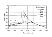
- this PBGF was taken out 1 m at a time and wound once each so that the diameter became 100 mm, 80 mm or 60 mm.
- the white light source was irradiated to the end surface of each PBGF, the core part was excited, and the transmission spectrum was measured. The result is shown in FIG.
- the PBGF used in this example can remove the ASE light having a wavelength of 1000 to 1100 nm guided through the core part by the filter effect by the photonic band gap and can stably oscillate light having a wavelength of about 1100 nm or more.
- the smaller the diameter of the optical fiber wound the more the obtained graph shifted to the longer wavelength side. Therefore, by changing the diameter when winding the optical fiber, the light for amplification with rare earth ions can be easily obtained.
- the gain profile of the fiber could be controlled.
- the gain profile of the rare-earth-ion-doped amplification optical fiber can be controlled while maintaining the ASE light removal effect.
- FIGS. 13A and 13B show the results when six semiconductor lasers having an oscillation wavelength of 915 nm and a maximum output of 0.45 W are used as excitation light sources.
- FIG. 13B shows the results when six semiconductor lasers having an oscillation wavelength of 915 nm and a maximum output of 2.2 W are used as excitation light sources.
- the present invention can be applied to an optical fiber laser capable of stably emitting a high-energy pulse.
Landscapes
- Physics & Mathematics (AREA)
- Electromagnetism (AREA)
- Engineering & Computer Science (AREA)
- Plasma & Fusion (AREA)
- Optics & Photonics (AREA)
- Lasers (AREA)
Abstract
Priority Applications (5)
| Application Number | Priority Date | Filing Date | Title |
|---|---|---|---|
| CN2009801057235A CN101946377B (zh) | 2008-02-19 | 2009-02-19 | 光纤激光器 |
| JP2009528933A JP4443627B2 (ja) | 2008-02-19 | 2009-02-19 | 光ファイバレーザ |
| EP09712490.3A EP2249443B1 (fr) | 2008-02-19 | 2009-02-19 | Laser à fibre optique |
| US12/859,604 US8270442B2 (en) | 2008-02-19 | 2010-08-19 | Optical fiber laser |
| US13/586,542 US8565273B2 (en) | 2008-02-19 | 2012-08-15 | Optical fiber laser |
Applications Claiming Priority (2)
| Application Number | Priority Date | Filing Date | Title |
|---|---|---|---|
| JP2008038005 | 2008-02-19 | ||
| JP2008-038005 | 2008-02-19 |
Related Child Applications (1)
| Application Number | Title | Priority Date | Filing Date |
|---|---|---|---|
| US12/859,604 Continuation US8270442B2 (en) | 2008-02-19 | 2010-08-19 | Optical fiber laser |
Publications (1)
| Publication Number | Publication Date |
|---|---|
| WO2009104691A1 true WO2009104691A1 (fr) | 2009-08-27 |
Family
ID=40985569
Family Applications (1)
| Application Number | Title | Priority Date | Filing Date |
|---|---|---|---|
| PCT/JP2009/052918 Ceased WO2009104691A1 (fr) | 2008-02-19 | 2009-02-19 | Laser à fibre optique |
Country Status (5)
| Country | Link |
|---|---|
| US (2) | US8270442B2 (fr) |
| EP (1) | EP2249443B1 (fr) |
| JP (1) | JP4443627B2 (fr) |
| CN (1) | CN101946377B (fr) |
| WO (1) | WO2009104691A1 (fr) |
Cited By (7)
| Publication number | Priority date | Publication date | Assignee | Title |
|---|---|---|---|---|
| WO2011007684A1 (fr) * | 2009-07-17 | 2011-01-20 | 住友電気工業株式会社 | Fibre cristalline photonique |
| JP2011060854A (ja) * | 2009-09-07 | 2011-03-24 | Fujikura Ltd | 増幅用光ファイバ、及び、それを用いたファイバレーザ装置 |
| WO2011037749A3 (fr) * | 2009-09-23 | 2011-05-19 | Coherent, Inc. | Appareil mopa à fibre doté d'une fibre de transport amplificatrice |
| JP2011243832A (ja) * | 2010-05-20 | 2011-12-01 | Miyachi Technos Corp | ファイバレーザ加工装置 |
| JP2014033098A (ja) * | 2012-08-03 | 2014-02-20 | Fujikura Ltd | ファイバレーザ装置 |
| JP2023121215A (ja) * | 2022-02-21 | 2023-08-31 | 株式会社フジクラ | ファイバレーザ装置 |
| WO2025037560A1 (fr) * | 2023-08-14 | 2025-02-20 | 株式会社フジクラ | Dispositif laser à fibre |
Families Citing this family (14)
| Publication number | Priority date | Publication date | Assignee | Title |
|---|---|---|---|---|
| JP2008283175A (ja) * | 2007-04-10 | 2008-11-20 | Fujikura Ltd | ファイバレーザ装置 |
| WO2012165588A1 (fr) * | 2011-06-03 | 2012-12-06 | 住友電気工業株式会社 | Dispositif de source de lumière et procédé de traitement |
| CN102513693B (zh) * | 2011-11-04 | 2014-08-06 | 杭州奥克光电设备有限公司 | 高功率光纤激光焊接机 |
| TWI473373B (zh) * | 2012-11-30 | 2015-02-11 | Ind Tech Res Inst | 間隔時間可調脈衝序列產生裝置 |
| JP5982307B2 (ja) * | 2013-03-14 | 2016-08-31 | 株式会社フジクラ | フォトニックバンドギャップファイバ、及び、それを用いたファイバレーザ装置 |
| FR3007536B1 (fr) * | 2013-06-24 | 2015-07-17 | Lyon Ecole Centrale | Composant optique a fibre |
| EP3074801A4 (fr) * | 2013-11-26 | 2017-07-05 | IPG Photonics Corporation | Fibre optique à fibre en mosaïque |
| US9634453B2 (en) * | 2014-12-06 | 2017-04-25 | Alcatel Lucent | Active optical isolators and active optical circulators |
| WO2017044799A1 (fr) * | 2015-09-10 | 2017-03-16 | Massachusetts Institute Of Technology | Systèmes, appareil et procédés pour amplification laser dans des amplificateurs à fibre |
| CN105576490A (zh) * | 2016-03-09 | 2016-05-11 | 中国科学院合肥物质科学研究院 | 一种利用GaN基激光二极管泵浦稀土离子掺杂激光材料实现激光及其倍频激光的方法 |
| EP3531513A4 (fr) * | 2016-10-21 | 2020-06-03 | Fujikura Ltd. | Dispositif laser à fibre |
| US11462878B2 (en) * | 2019-05-23 | 2022-10-04 | Lawrence Livermore National Security, Llc | All solid hybrid arrow fiber |
| JP2020194937A (ja) * | 2019-05-30 | 2020-12-03 | 住友電気工業株式会社 | 光増幅器 |
| CN114883898B (zh) * | 2022-05-24 | 2024-06-11 | 西安工业大学 | 一种阵列分布式的大功率全光纤激光放大器 |
Citations (2)
| Publication number | Priority date | Publication date | Assignee | Title |
|---|---|---|---|---|
| JP2007208107A (ja) * | 2006-02-03 | 2007-08-16 | Hitachi Cable Ltd | 光ファイバレーザ |
| JP2007316526A (ja) * | 2006-05-29 | 2007-12-06 | Fujikura Ltd | フォトニックバンドギャップファイバ及びファイバレーザ |
Family Cites Families (19)
| Publication number | Priority date | Publication date | Assignee | Title |
|---|---|---|---|---|
| JPH03242627A (ja) | 1990-02-20 | 1991-10-29 | Nippon Telegr & Teleph Corp <Ntt> | 多段光増幅装置 |
| JP2653936B2 (ja) | 1991-05-17 | 1997-09-17 | 沖電気工業株式会社 | 光増幅器 |
| JP2977053B2 (ja) | 1991-07-12 | 1999-11-10 | 安藤電気株式会社 | 高出力光パルス発生器 |
| JPH05136498A (ja) | 1991-07-22 | 1993-06-01 | Oki Electric Ind Co Ltd | 光増幅器 |
| US5659644A (en) | 1996-06-07 | 1997-08-19 | Lucent Technologies Inc. | Fiber light source with multimode fiber coupler |
| US5864644A (en) | 1997-07-21 | 1999-01-26 | Lucent Technologies Inc. | Tapered fiber bundles for coupling light into and out of cladding-pumped fiber devices |
| US6788865B2 (en) * | 2000-03-03 | 2004-09-07 | Nippon Telegraph And Telephone Corporation | Polarization maintaining optical fiber with improved polarization maintaining property |
| FR2811437A1 (fr) * | 2000-07-06 | 2002-01-11 | Cit Alcatel | Fibre optique a pompage par la gaine et procede de fabrication d'une telle fibre |
| JP2003035919A (ja) | 2000-11-07 | 2003-02-07 | Furukawa Electric Co Ltd:The | 光増幅装置および光伝送システム |
| US6937627B2 (en) * | 2002-01-05 | 2005-08-30 | Jian Lin | Stable and high speed full range laser wavelength tuning with reduced group delay and temperature variation compensation |
| WO2005041367A1 (fr) * | 2003-10-24 | 2005-05-06 | Nkt Research & Innovation A/S | Systeme optique pour la production d'impulsions laser breves |
| US20050207455A1 (en) * | 2003-12-15 | 2005-09-22 | Maccormack Stuart | Method and apparatus for efficient coupling of pump light into fiber amplifiers |
| JP2006093613A (ja) * | 2004-09-27 | 2006-04-06 | Sumitomo Electric Ind Ltd | 光ファイバ、光ファイバ増幅器及び光ファイバレーザ光源 |
| JP4561314B2 (ja) * | 2004-10-28 | 2010-10-13 | 日立電線株式会社 | ファイバレーザ用光ファイバ、ファイバレーザ及びレーザ発振方法 |
| US7430352B2 (en) * | 2005-07-29 | 2008-09-30 | Aculight Corporation | Multi-segment photonic-crystal-rod waveguides for amplification of high-power pulsed optical radiation and associated method |
| JP4699131B2 (ja) * | 2005-08-05 | 2011-06-08 | 株式会社フジクラ | 光ファイバレーザ、光ファイバ増幅器、mopa方式光ファイバレーザ |
| US7171091B1 (en) * | 2005-08-15 | 2007-01-30 | The United States Of America As Represented By The Secretary Of The Air Force | Tuned cladding fiber amplifier and laser |
| EP1946412A2 (fr) * | 2005-10-11 | 2008-07-23 | Clear Align LLC | Appareil et methode pour generer de courtes impulsions optiques |
| JP2007207856A (ja) * | 2006-01-31 | 2007-08-16 | Miyachi Technos Corp | ファイバレーザ加工装置 |
-
2009
- 2009-02-19 JP JP2009528933A patent/JP4443627B2/ja active Active
- 2009-02-19 WO PCT/JP2009/052918 patent/WO2009104691A1/fr not_active Ceased
- 2009-02-19 CN CN2009801057235A patent/CN101946377B/zh not_active Expired - Fee Related
- 2009-02-19 EP EP09712490.3A patent/EP2249443B1/fr not_active Not-in-force
-
2010
- 2010-08-19 US US12/859,604 patent/US8270442B2/en active Active
-
2012
- 2012-08-15 US US13/586,542 patent/US8565273B2/en active Active
Patent Citations (2)
| Publication number | Priority date | Publication date | Assignee | Title |
|---|---|---|---|---|
| JP2007208107A (ja) * | 2006-02-03 | 2007-08-16 | Hitachi Cable Ltd | 光ファイバレーザ |
| JP2007316526A (ja) * | 2006-05-29 | 2007-12-06 | Fujikura Ltd | フォトニックバンドギャップファイバ及びファイバレーザ |
Cited By (7)
| Publication number | Priority date | Publication date | Assignee | Title |
|---|---|---|---|---|
| WO2011007684A1 (fr) * | 2009-07-17 | 2011-01-20 | 住友電気工業株式会社 | Fibre cristalline photonique |
| JP2011060854A (ja) * | 2009-09-07 | 2011-03-24 | Fujikura Ltd | 増幅用光ファイバ、及び、それを用いたファイバレーザ装置 |
| WO2011037749A3 (fr) * | 2009-09-23 | 2011-05-19 | Coherent, Inc. | Appareil mopa à fibre doté d'une fibre de transport amplificatrice |
| JP2011243832A (ja) * | 2010-05-20 | 2011-12-01 | Miyachi Technos Corp | ファイバレーザ加工装置 |
| JP2014033098A (ja) * | 2012-08-03 | 2014-02-20 | Fujikura Ltd | ファイバレーザ装置 |
| JP2023121215A (ja) * | 2022-02-21 | 2023-08-31 | 株式会社フジクラ | ファイバレーザ装置 |
| WO2025037560A1 (fr) * | 2023-08-14 | 2025-02-20 | 株式会社フジクラ | Dispositif laser à fibre |
Also Published As
| Publication number | Publication date |
|---|---|
| EP2249443A4 (fr) | 2013-09-04 |
| US20100329288A1 (en) | 2010-12-30 |
| EP2249443A1 (fr) | 2010-11-10 |
| CN101946377A (zh) | 2011-01-12 |
| US20120307848A1 (en) | 2012-12-06 |
| JPWO2009104691A1 (ja) | 2011-06-23 |
| JP4443627B2 (ja) | 2010-03-31 |
| US8270442B2 (en) | 2012-09-18 |
| US8565273B2 (en) | 2013-10-22 |
| EP2249443B1 (fr) | 2020-07-08 |
| CN101946377B (zh) | 2012-11-07 |
Similar Documents
| Publication | Publication Date | Title |
|---|---|---|
| JP4443627B2 (ja) | 光ファイバレーザ | |
| JP5238509B2 (ja) | フォトニックバンドギャップファイバ | |
| JP5185929B2 (ja) | ファイバレーザ | |
| JP4243327B2 (ja) | フォトニックバンドギャップファイバ及びファイバ増幅器 | |
| CA2693854C (fr) | Dispositif emettant de la lumiere avec un verre de phosphosilicate | |
| US8498044B2 (en) | Amplification optical fiber, and optical fiber amplifier and resonator using the same | |
| EP3005496B1 (fr) | Laser à fibre fabry-perot multimodal | |
| JP2010129886A (ja) | ファイバレーザ用光ファイバ及びファイバレーザ | |
| CN101569066B (zh) | 光纤激光器 | |
| JP7177090B2 (ja) | 高パワークラッディングポンプ単一モードファイバーラマンレーザー | |
| US11835776B2 (en) | Filter device and laser apparatus | |
| WO2024213586A1 (fr) | Fibre optique et dispositif à fibre optique | |
| WO2021045074A1 (fr) | Dispositif d'amplification optique | |
| US20090041063A1 (en) | Fiber laser apparatus | |
| JP5014640B2 (ja) | マルチモードファイバ、光増幅器及びファイバレーザ | |
| JP7495804B2 (ja) | 活性元素添加光ファイバ、共振器、及び、ファイバレーザ装置 | |
| JP2010177314A (ja) | ダブルクラッドファイバ、ファイバレーザ装置及び光増幅器 | |
| JP2001358388A (ja) | 光ファイバ、光ファイバアンプ及びファイバレーザー | |
| WO2007077419A1 (fr) | Fibre optique a coeur incline | |
| WO2020139707A1 (fr) | Dispositifs à fibre optique et procédés de réduction de l'intensité lumineuse par diffusion raman stimulée (srs) dans des systèmes combinés de signaux |
Legal Events
| Date | Code | Title | Description |
|---|---|---|---|
| WWE | Wipo information: entry into national phase |
Ref document number: 200980105723.5 Country of ref document: CN |
|
| ENP | Entry into the national phase |
Ref document number: 2009528933 Country of ref document: JP Kind code of ref document: A |
|
| 121 | Ep: the epo has been informed by wipo that ep was designated in this application |
Ref document number: 09712490 Country of ref document: EP Kind code of ref document: A1 |
|
| NENP | Non-entry into the national phase |
Ref country code: DE |
|
| WWE | Wipo information: entry into national phase |
Ref document number: 2009712490 Country of ref document: EP |