WO2009107236A1 - パック電池の充電装置及びパック電池の品質判定装置 - Google Patents
パック電池の充電装置及びパック電池の品質判定装置 Download PDFInfo
- Publication number
- WO2009107236A1 WO2009107236A1 PCT/JP2008/053664 JP2008053664W WO2009107236A1 WO 2009107236 A1 WO2009107236 A1 WO 2009107236A1 JP 2008053664 W JP2008053664 W JP 2008053664W WO 2009107236 A1 WO2009107236 A1 WO 2009107236A1
- Authority
- WO
- WIPO (PCT)
- Prior art keywords
- cell
- voltage value
- value
- secondary battery
- battery pack
- Prior art date
- Legal status (The legal status is an assumption and is not a legal conclusion. Google has not performed a legal analysis and makes no representation as to the accuracy of the status listed.)
- Ceased
Links
Images


Classifications
-
- G—PHYSICS
- G01—MEASURING; TESTING
- G01R—MEASURING ELECTRIC VARIABLES; MEASURING MAGNETIC VARIABLES
- G01R31/00—Arrangements for testing electric properties; Arrangements for locating electric faults; Arrangements for electrical testing characterised by what is being tested not provided for elsewhere
- G01R31/36—Arrangements for testing, measuring or monitoring the electrical condition of accumulators or electric batteries, e.g. capacity or state of charge [SoC]
- G01R31/382—Arrangements for monitoring battery or accumulator variables, e.g. SoC
- G01R31/3842—Arrangements for monitoring battery or accumulator variables, e.g. SoC combining voltage and current measurements
-
- G—PHYSICS
- G01—MEASURING; TESTING
- G01R—MEASURING ELECTRIC VARIABLES; MEASURING MAGNETIC VARIABLES
- G01R31/00—Arrangements for testing electric properties; Arrangements for locating electric faults; Arrangements for electrical testing characterised by what is being tested not provided for elsewhere
- G01R31/36—Arrangements for testing, measuring or monitoring the electrical condition of accumulators or electric batteries, e.g. capacity or state of charge [SoC]
- G01R31/389—Measuring internal impedance, internal conductance or related variables
-
- G—PHYSICS
- G01—MEASURING; TESTING
- G01R—MEASURING ELECTRIC VARIABLES; MEASURING MAGNETIC VARIABLES
- G01R31/00—Arrangements for testing electric properties; Arrangements for locating electric faults; Arrangements for electrical testing characterised by what is being tested not provided for elsewhere
- G01R31/36—Arrangements for testing, measuring or monitoring the electrical condition of accumulators or electric batteries, e.g. capacity or state of charge [SoC]
- G01R31/392—Determining battery ageing or deterioration, e.g. state of health
-
- H—ELECTRICITY
- H01—ELECTRIC ELEMENTS
- H01M—PROCESSES OR MEANS, e.g. BATTERIES, FOR THE DIRECT CONVERSION OF CHEMICAL ENERGY INTO ELECTRICAL ENERGY
- H01M10/00—Secondary cells; Manufacture thereof
- H01M10/42—Methods or arrangements for servicing or maintenance of secondary cells or secondary half-cells
- H01M10/44—Methods for charging or discharging
- H01M10/441—Methods for charging or discharging for several batteries or cells simultaneously or sequentially
-
- H—ELECTRICITY
- H01—ELECTRIC ELEMENTS
- H01M—PROCESSES OR MEANS, e.g. BATTERIES, FOR THE DIRECT CONVERSION OF CHEMICAL ENERGY INTO ELECTRICAL ENERGY
- H01M10/00—Secondary cells; Manufacture thereof
- H01M10/42—Methods or arrangements for servicing or maintenance of secondary cells or secondary half-cells
- H01M10/48—Accumulators combined with arrangements for measuring, testing or indicating the condition of cells, e.g. the level or density of the electrolyte
- H01M10/482—Accumulators combined with arrangements for measuring, testing or indicating the condition of cells, e.g. the level or density of the electrolyte for several batteries or cells simultaneously or sequentially
-
- H—ELECTRICITY
- H02—GENERATION; CONVERSION OR DISTRIBUTION OF ELECTRIC POWER
- H02J—ELECTRIC POWER NETWORKS; CIRCUIT ARRANGEMENTS OR SYSTEMS FOR SUPPLYING OR DISTRIBUTING ELECTRIC POWER; SYSTEMS FOR STORING ELECTRIC ENERGY
- H02J7/00—Circuit arrangements for charging or discharging batteries or for supplying loads from batteries
- H02J7/50—Circuit arrangements for charging or discharging batteries or for supplying loads from batteries acting upon multiple batteries simultaneously or sequentially
-
- H—ELECTRICITY
- H01—ELECTRIC ELEMENTS
- H01M—PROCESSES OR MEANS, e.g. BATTERIES, FOR THE DIRECT CONVERSION OF CHEMICAL ENERGY INTO ELECTRICAL ENERGY
- H01M10/00—Secondary cells; Manufacture thereof
- H01M10/42—Methods or arrangements for servicing or maintenance of secondary cells or secondary half-cells
- H01M10/425—Structural combination with electronic components, e.g. electronic circuits integrated to the outside of the casing
- H01M2010/4271—Battery management systems including electronic circuits, e.g. control of current or voltage to keep battery in healthy state, cell balancing
-
- H—ELECTRICITY
- H02—GENERATION; CONVERSION OR DISTRIBUTION OF ELECTRIC POWER
- H02J—ELECTRIC POWER NETWORKS; CIRCUIT ARRANGEMENTS OR SYSTEMS FOR SUPPLYING OR DISTRIBUTING ELECTRIC POWER; SYSTEMS FOR STORING ELECTRIC ENERGY
- H02J7/00—Circuit arrangements for charging or discharging batteries or for supplying loads from batteries
- H02J7/50—Circuit arrangements for charging or discharging batteries or for supplying loads from batteries acting upon multiple batteries simultaneously or sequentially
- H02J7/52—Circuit arrangements for charging or discharging batteries or for supplying loads from batteries acting upon multiple batteries simultaneously or sequentially for charge balancing, e.g. equalisation of charge between batteries
-
- Y—GENERAL TAGGING OF NEW TECHNOLOGICAL DEVELOPMENTS; GENERAL TAGGING OF CROSS-SECTIONAL TECHNOLOGIES SPANNING OVER SEVERAL SECTIONS OF THE IPC; TECHNICAL SUBJECTS COVERED BY FORMER USPC CROSS-REFERENCE ART COLLECTIONS [XRACs] AND DIGESTS
- Y02—TECHNOLOGIES OR APPLICATIONS FOR MITIGATION OR ADAPTATION AGAINST CLIMATE CHANGE
- Y02E—REDUCTION OF GREENHOUSE GAS [GHG] EMISSIONS, RELATED TO ENERGY GENERATION, TRANSMISSION OR DISTRIBUTION
- Y02E60/00—Enabling technologies; Technologies with a potential or indirect contribution to GHG emissions mitigation
- Y02E60/10—Energy storage using batteries
Definitions
- the present invention relates to a battery pack charging device and a battery pack quality determination device, and in particular, to determine a battery pack charging device and a battery pack quality for charging a battery pack in which a plurality of secondary battery cells are connected in series.
- the present invention relates to a quality determination device for a battery pack.
- Secondary batteries such as nickel cadmium batteries, nickel metal hydride batteries, and lithium ion batteries are batteries that can be used repeatedly by repeating discharge and charge cycles. However, if the secondary battery cell is charged a plurality of times, the storage capacity of the secondary battery is reduced compared to the initial stage due to overcharge or deterioration of the electrolyte or electrode plate of the secondary battery. As the battery deteriorates, the secondary battery cell can no longer be used.
- the main factor of deterioration of the secondary battery is overcharge, and a method of performing charging while preventing overcharge is known (for example, see Patent Document 1 to Patent Document 4). Japanese Patent No. 3913443 Japanese Patent No. 3539123 Japanese Patent No. 3430439 Japanese Patent No. 3752249
- the present invention prevents a reduction in charge / discharge performance when charging a battery pack, improves the battery pack reliability, and can ensure the battery pack safety and the battery pack battery.
- a quality judgment apparatus is provided.
- the battery pack charging apparatus is a battery pack charging apparatus for charging a battery pack in which a plurality of secondary battery cells are connected in series, wherein the battery pack has a predetermined charge.
- Voltage supply means for supplying voltage
- cell voltage value detection means for detecting a cell voltage value for each secondary battery cell constituting the battery pack
- charge control means for controlling a charge voltage supplied to the battery pack.
- the charge control means includes a dispersion degree calculation means for calculating a dispersion degree of a secondary battery cell based on the cell voltage value detected by the cell voltage value detection means, and the dispersion degree calculation means.
- Maximum value specifying means for specifying the maximum value of the cell voltage value based on the calculated degree of dispersion of the secondary battery cells, and the maximum value of the cell voltage value specified by the maximum value specifying means are preset. Determining means for determining whether or not the allowable cell voltage value has been reached, and if the determination means determines that the maximum cell voltage value is greater than the allowable cell voltage value, the maximum cell voltage value and the allowable cell Charging voltage value changing means for changing the charging voltage applied by the voltage supply means based on the voltage difference with the voltage value.
- the cell voltage value detecting means is further provided with a detection terminal for detecting a terminal cell voltage value for each secondary battery cell constituting the battery pack, Based on the potential difference between the terminal cell voltage value of the secondary battery cell and the terminal cell voltage value of the secondary battery cell on the low potential side with respect to the secondary battery cell to be detected, the cell of the secondary battery cell to be detected The voltage value is detected.
- the battery pack charging apparatus of the present invention further comprises current value detection means for detecting a current value flowing through the battery pack, and the charge control means is configured to fully charge a charge voltage to the battery pack.
- a voltage value switching means for switching between a predetermined charging voltage value that exceeds the equilibrium potential value but does not reach the irreversible chemical reaction region, and a check voltage value that is set based on the fully charged equilibrium potential value, and the voltage value switching means The cell voltage value of the secondary battery cell detected by the cell voltage value detection means in a state where the battery pack is switched so that a predetermined charging voltage value is applied to the battery pack, and the battery voltage by the voltage value switching means.
- the cell voltage value of the secondary battery cell detected by the cell voltage value detection means in a state where the check voltage value is switched to be applied, and the current value detection means An internal resistance value calculating means for calculating an internal resistance value of the secondary battery cell based on the output current value, and a secondary voltage based on the internal resistance value of the secondary battery cell calculated by the internal resistance value. It comprises a soundness degree calculation means for calculating the soundness degree of the battery cell.
- the charge control means further calculates a remaining charge amount of the secondary battery cell based on the current value detected during the charge and the current value of the discharge current. It has quantity calculation means.
- the battery pack quality determination apparatus is a battery pack quality determination apparatus for determining the quality of a battery pack in which a plurality of secondary battery cells are connected in series.
- Voltage supply means for supplying a predetermined external voltage to the battery
- cell voltage value detection means for detecting a cell voltage value for each secondary battery cell constituting the battery pack
- quality determination means for determining the quality of the battery pack
- the quality determination means includes a dispersion degree calculation means for calculating a dispersion degree of a secondary battery cell based on the cell voltage value detected by the cell voltage value detection means, and the dispersion degree calculation means.
- Maximum value specifying means for specifying the maximum value of the cell voltage value based on the calculated degree of dispersion of the secondary battery cells, and the maximum value of the cell voltage value specified by the maximum value specifying means are preset. Is made of comprises a determination means for determining whether reaches the allowable cell voltage value.
- the cell voltage value detection means is further provided with a detection terminal for detecting a terminal cell voltage value for each secondary battery cell constituting the battery pack, and is a detection target. Based on the potential difference between the terminal cell voltage value of the secondary battery cell and the terminal cell voltage value of the secondary battery cell on the low potential side relative to the secondary battery cell to be detected, the secondary battery cell of the detection target The cell voltage value is detected.
- the battery pack further includes a current value detection unit that detects a current value flowing through the battery pack, and the quality determination unit applies an external voltage to the battery pack.
- Voltage value switching means for switching off, and cell voltage of the secondary battery cell detected by the cell voltage value detection means in a state switched by the voltage value switching means so that a predetermined external voltage is applied to the battery pack Value, the cell voltage value of the secondary battery cell detected by the cell voltage value detection means in a state where the external voltage is switched to the battery pack by the voltage value switching means, and the current value detection
- An internal resistance value calculating means for calculating an internal resistance value of the secondary battery cell based on the current value detected by the means, and a secondary battery calculated by the internal resistance value Based on an internal resistance value of Le is made by and a health calculation means for calculating the health of the secondary battery cell.
- the battery pack charging apparatus it is possible to prevent the charge / discharge performance from being reduced when charging the battery pack, to improve the reliability of the battery pack, and to ensure safety. Furthermore, by providing a detection terminal for each secondary battery cell, the cell voltage value of each secondary battery cell can be easily detected, and variations in characteristics of the secondary battery cells can be easily determined. Furthermore, the secondary battery cell is an index that indicates the progress of deterioration of the secondary battery such as a battery pack when the highest charging voltage is applied while being able to be charged without causing overcharge. Since the user can know the replacement time of the whole battery pack, the reliability and safety of the battery pack can be improved. Furthermore, it is possible to easily determine the charging timing of the battery pack from the remaining power storage amount by sequentially detecting how the remaining power storage amount of the battery pack has changed from the beginning.
- the quality determination apparatus for a battery pack it is possible to prevent a reduction in charge / discharge performance when charging the battery pack, improve the reliability of the battery pack, and ensure safety. Furthermore, by providing a detection terminal for each secondary battery cell, the cell voltage value of each secondary battery cell can be easily detected, and variations in characteristics of the secondary battery cells can be easily determined. Furthermore, since the user can know the replacement time of the whole battery pack from the soundness level of the secondary battery cell to which the highest charging voltage is applied, the reliability and safety of the battery pack can be improved.
- the charging device 40 of the battery pack 10 in which the secondary battery cells 10a are connected in series will be described.
- the pack battery 10 used in the present embodiment has ten secondary battery cells 10a connected in series (see FIG. 2).
- the charging device 40 includes a voltage supply device 41, a cell voltage value detection device 42, a charge control device 43, a current value detection device 44, and a display device 46.
- the voltage supply device 41 supplies a predetermined charging voltage to the battery pack 10
- the cell voltage value detection device 42 is a cell voltage value v for each secondary battery cell 10 a constituting the battery pack 10. m is detected.
- the charge control device 43 controls the charging voltage supplied to the battery pack 10, and the current value detection device 44 detects the current value J flowing through the battery pack 10,
- the display device 46 displays a soundness level SOH (State Of Health), a remaining power storage amount Q acum , and the like.
- SOH State Of Health
- the soundness level SOH is an index indicating the progress of deterioration of a secondary battery such as the battery pack 10, and is generally expressed as a ratio of “current storage capacity” to “initial storage capacity”. Since the product of the storage capacity and the internal resistance is constant, the present invention is represented by the inverse ratio of the “current internal resistance value of the secondary battery” to the “initial internal resistance value”.
- the charging control device 43 includes a storage unit 50, a voltage value switching unit 45, an increment unit 51, a first determination unit 52, a second determination unit 53, a dispersion degree calculation unit 61, a maximum A value specifying unit 62, a third determination unit 63, a charging voltage value changing unit 64, an internal resistance value calculating unit 65, a soundness calculating unit 66, and a remaining power storage amount calculating unit 67 are provided.
- the charging control device 43 includes a CPU that executes various processes, a memory that stores various processing programs, and the like.
- the storage unit 50 is full and charge balanced voltage value E eq lowest check voltage E c is lower than the packed battery 10, exceeds ⁇ charge balanced voltage value E eq but given that does not reach the irreversible chemical reaction region a charging voltage value E a, is for storing the voltage value ⁇ E of the predetermined step size.
- the voltage value switching unit 45 sets the charging voltage to the battery pack 10 to a predetermined charging voltage value E a that exceeds the full charge equilibrium potential value E eq but does not reach the irreversible chemical reaction region, and a full charge equilibrium potential value. is intended to switch the E eq to the check voltage E c is set to the reference.
- the first determination unit 52 includes a increment unit 51 adds the voltage value ⁇ E of the predetermined step size to check voltage E c until then sets a new check voltage value E c, the current value detection detected by the device 44 the current value J is intended to determine whether it is less than previously inputted set criterion value J c.
- the second determination unit 53 determines the time required from the previous affirmation determination to the current affirmation determination by the first determination unit 52 as the required time from the previous affirmation determination to the previous affirmation determination. It is determined whether or not r (r is a real number greater than or equal to 1) times.
- the dispersion degree calculation unit 61 is for calculating the degree of dispersion of the secondary battery cells 10a sigma based on the cell voltage value detection device cell voltage value detected by the 42 v m.
- the degree of dispersion ⁇ represents the variation in characteristics of the secondary battery cell 10a based on the voltage value.
- the maximum value specifying unit 62 determines a maximum applied cell voltage value v maxon that is a maximum value of the applied cell voltage value v mon based on the dispersion degree ⁇ of the secondary battery cell calculated by the dispersion degree calculating unit 61. It is something to identify.
- the third determination unit 63 is to determine whether the maximum applied during cell voltage value v maxon identified has reached the allowable cell voltage value v c, which is set in advance by the maximum value specifying unit 62 .
- the charging voltage value changing unit 64 determines that the maximum applied cell voltage value v maxon is acceptable. based on a voltage difference between the cell voltage value v c, and changes the charging voltage value E a, which is applied by the voltage source 41.
- the internal resistance value calculation unit 65 is switched by the cell voltage value detection device 42 in a state where the voltage value switching unit 45 is switched to apply a predetermined charging voltage value Ea to the battery pack 10.
- the cell internal resistance value R of the secondary battery cell 10a. m is calculated.
- the soundness level calculation unit 66 calculates the cell soundness level SOH m of the most deteriorated secondary battery cell 10M having the maximum applied cell voltage value v maxon in the maximum value specifying unit 62, and the internal resistance value Based on the cell internal resistance value R m of the most deteriorated secondary battery cell 10M calculated by the calculation unit 65, the cell soundness SOH m of the most deteriorated secondary battery cell 10M is calculated.
- the remaining power storage amount calculation unit 67 calculates the remaining power storage amount Q acum of the secondary battery cell 10a based on the current value J detected during charging and the discharge current value J out detected during discharging. It is.
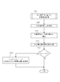
- the charging control device 43 controls charging of the battery pack 10 according to the following steps. First, as shown in FIG. 3, the said battery pack 10 at the lowest check voltage E c by a minute time T 2 applied (step S10), and during the fine small time T 2, by the current value detection device 44 A current value J flowing through the battery pack 10 is detected (step S20).
- step S30 the first a judgment of the detected current value J by the determination unit 52 (step S30), if said current value J exceeds the said criterion value J c, by the voltage value changeover portion 45 by switching the charging voltage to the predetermined charging voltage value E a, the predetermined time T 1 is applied to the battery pack 10 at the predetermined charging voltage value E a (step S40). Then, switching the charge voltage to the lowest check voltage E c by the voltage value changeover portion 45, the flow returns to the step S10.
- the by increment unit 51 adds the voltage value ⁇ E of the predetermined step size to check voltage E c to it, the new check voltage setting the E c (step S50).
- step S60 the switching voltage value switching charge voltage by section 45 to the predetermined charging voltage value E a, the battery pack 10 at the predetermined charging voltage value E a predetermined time T 1 is applied (step S60).
- step S60 while the charging voltage value E a by a predetermined time T 1 applied to charge voltage control based on the cell voltage values (step S65).
- step S70 the switching of the charging voltage by a voltage value changeover portion 45 to the new check voltage value E c wherein, the new check voltage battery pack 10 minute time T 2 is applied at E c (step S70).
- this short time T 2 to calculate from the cell internal resistance value R m of the most deteriorated secondary cell 10M cell soundness SOH m of the most deteriorated secondary cell 10M (step S75).
- step S90 the first a judgment of the detected current value J by the determination unit 52 (step S90), if said current value J exceeds the said criterion value J c, returns to the step S50, said current if the value J is sufficient that the following the criterion value J c, the process proceeds to the next step S100.
- step S ⁇ b> 100 the second determination unit 53 determines a required time from the previous positive determination by the first determination unit 52 to the current positive determination. if the determination unit 52 required time between the time required N e between until a positive determination of the current from the positive determination of the last from the positive determination of the second last until a positive determination of the last N e-1 for r times less by, returns to step S50 (see FIG.
- the full charge equilibrium voltage value of the battery pack 10 regardless of the type or model number of the battery pack 10 (secondary battery cell 10a). While searching for E eq , the battery can be charged so that the charging rate is approximately 100%. Further, it is effective even when a part of the internal structure of the battery pack 10 is damaged and deteriorated, that is, when a part of the secondary battery cells 10a constituting the battery pack 10 is damaged. Then, the current fully charged equilibrium voltage value E eq of the battery pack 10 can be found and charged to be approximately 100% of the current storage capacity.
- the charging voltage control based on the cell voltage value is performed in the following steps.
- the applied cell voltage value v mon is detected using the applied terminal cell voltage value V mon of each of the secondary battery cells 10a, 10a,... Constituting the battery pack 10 (step S210).
- a cell voltage value detection method for each of the secondary battery cells 10a, 10a,... Constituting the battery pack 10 will be described.
- the cell voltage value detection device 42 of the present embodiment is provided with a detection terminal 42 a that detects an applied terminal cell voltage value V mon for each secondary battery cell 10 a constituting the battery pack 10. It has been.
- This detection terminal 42a, the secondary battery cells 10a one minute of application at the terminal cell voltage value V 1on, secondary cells 10a during two pieces of the application terminal cell voltage value V 2on ⁇ ⁇ ⁇ and the secondary battery cell It is possible to detect the terminal cell voltage value V mon for m of 10a (m is an integer satisfying 1 ⁇ m ⁇ N).
- the applied terminal cell voltage value V mon the applied cell voltage value v mon of each secondary battery cell 10a is calculated by Equation 1.
- the applied terminal cell voltage value V mon of the detection target (m-th) secondary battery cell 10a and the detection target secondary battery cell 10a Based on the potential difference from the applied terminal cell voltage value V (m ⁇ 1) on of the low potential side secondary battery cell 10a, the applied cell voltage value v of the detection target (mth) secondary battery cell 10a mon is detected. Therefore, it becomes easy to detect the cell voltage value v mon at the time of application of the secondary battery cell 10a, and the variation in characteristics can be easily determined.
- the degree of dispersion ⁇ and the dispersion index dev m are calculated using the applied cell voltage value v mon and the applied average voltage value V MEANon of each secondary battery cell 10a (step S220).
- the average voltage value V MEANon at the time of application of each secondary battery cell 10a is calculated by Equation 3.
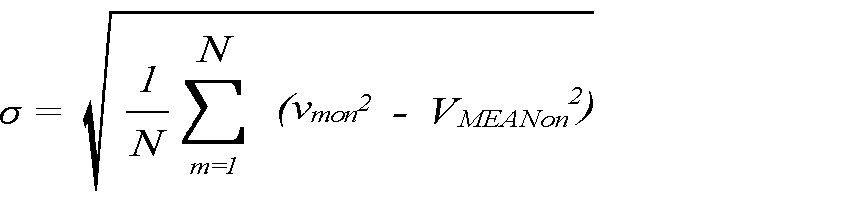
- the dispersion degree ⁇ of the cell voltage value v mon at the time of application of the secondary battery cell 10a is calculated by Equation 4.
- the dispersion index dev m is calculated by Equation 5 from the degree of dispersion ⁇ , the applied average voltage value V MEANon , and the applied cell voltage value v mon of each secondary battery cell 10a.
- the dispersion index dev m is an index representing the degree of variation in the characteristics of the secondary battery cells 10a described above for each secondary battery cell 10a.
- Step S230 based on the dispersion degree ⁇ of the secondary battery cell 10a calculated by the dispersion degree calculation unit 61 by the maximum value specifying unit 62, the cell voltage described above from the dispersion index dev m calculated in step S220. Specify the maximum value. (Step S230).
- the maximum applied cell voltage value v maxon from which the maximum dispersion index dev m is obtained is identified by comparing the dispersion index dev m of each secondary battery cell 10a calculated in step S220.
- the maximum applied during cell voltage value v outermost deterioration secondary battery cell 10M which indicates maxon are other secondary battery cells 10a and the cell internal resistance value R m is different from the secondary battery cells 10a, i.e., degraded It is highly possible that the battery is overcharged.
- step S240 whether the identified cell maximum applied during cell voltage value v maxon has reached the allowable cell voltage value v c, which is set in advance by the maximum value specifying unit 62 using the third determination unit 63 Determination is made (step S240).
- the maximum voltage cell voltage value v maxon at the time of application is set so that the charging voltage value change unit 264 drops the applied voltage value V Son according to Equation 6. based on a voltage difference between the permissible cell voltage value v c, to change the charging voltage value E a, which is applied by the voltage supply device 41 (step S250).
- the charging voltage control based on the cell voltage value is terminated. Further, if it is determined that the maximum applied during cell voltage value v maxon is equal to or less than the allowable cell voltage value v c ends the charging voltage control based on the cell voltage value.
- the permissible cell voltage value v c are defined for each type of secondary battery cells, for example, it is defined as 4.2V for lithium-ion batteries.
- step S75 the flow of calculation of the cell soundness SOH m of the most deteriorated secondary battery cell 10M performed in step S75 will be described.
- the calculation of the cell soundness SOH m of the most deteriorated secondary battery cell 10M is performed in the following steps.
- the cell voltage value vmoff at the time of closed circuit and the current value J are detected (step S310).
- the closed-circuit cell voltage value is calculated from the closed-circuit terminal cell voltage V moff and V (m ⁇ 1) off using Equation 3.
- the current value J is detected by using the current value detection device 44.
- the cell internal resistance value R m is calculated from Equation 7.
- Secondary cells 10a for which to calculate the cell internal resistance value R m is the most deteriorated secondary cell 10M which maximum dispersion index dev m was obtained. Note that the secondary battery cell 10a is not limited to the most deteriorated secondary battery cell 10M, and any secondary battery cell 10a may be targeted.
- the initial cell internal resistance value R mint is calculated from Equation 7.
- ⁇ m m is a voltage difference between the applied cell voltage value v mon of each secondary battery cell 10a and the closed circuit cell voltage value v moff of each secondary battery cell 10a, and is calculated by Equation 8.
- the cell health SOH m which is an index indicating the progress of deterioration of the secondary battery cell 10a, is calculated by the health calculator 66 (step S330).
- the cell soundness SOH m is an index indicating the progress of deterioration of the secondary battery cell 10a, and is expressed as a ratio of the current storage capacity to the initial storage capacity, and the product of the storage capacity and the internal resistance is constant. since, it expressed in inverse ratio to the initial cell internal resistance value R mint current cell internal resistance value R m, when the initial cell internal resistance value R mint, can be calculated by equation 9.
- the cell soundness level SOH m can be calculated from the current cell internal resistance value R m .
- the initial cell internal resistance value R mint is substituted for the cell internal resistance value R m, and as a result, the cell soundness SOH m is 100.
- step S340 the soundness SOH calculated in step S330 is displayed on the display unit 46 (step S340).
- Cell internal resistance value R m of each secondary cell 10a has been found to take a substantially constant value until the charging end. Once the charge end, the cell internal resistance value with an irreversible chemical reaction R m is generally large. Thus if the charging rate up to about 70%, it is possible to accurately calculate the respective secondary battery cells 10a original cell internal resistance value R m.
- the cell internal resistance value R m is calculated using the applied cell voltage value v mon , the closed circuit cell voltage value v moff , and the current value J.
- the internal resistance value R of the battery pack 10 as a whole is calculated by substituting the voltage value V Son , the closed-circuit total voltage value V Soff , and the current value J into Equations 7 and 8, or the internal resistance value R and the initial internal value It is also possible to calculate the soundness level SOH of the entire battery pack 10 by substituting the resistance value R int into Equation 9.
- the remaining storage amount Q acum of the battery pack 10 is calculated by integrating the current value J detected in step S210 by the remaining storage amount calculation unit 67 (step S350).
- the remaining power storage amount Q acum is equal to an integrated value Q charge obtained by integrating the current value J of the battery pack 10 over time.
- step S350 the remaining power storage amount Q acum calculated in step S350 is displayed on the display unit 46 (step S360).
- the charging device 40 of this embodiment of the secondary cells 10a constituting the packed battery 10, and identify the most charge voltage value most deteriorated secondary cell 10M which E a is applied, the It is possible to perform charging while applying the charging voltage value Ea applied to the most deteriorated secondary battery cell 10M to a predetermined value or less, and individually apply the cell voltage value vmon at the time of application of each secondary battery cell 10a. Since it is configured not to control but to control the total voltage value V Son at the time of application of the battery pack 10, it is possible to prevent a reduction in charge / discharge performance when charging the battery pack 10, and to improve the reliability of the battery pack 10. And safety can be ensured. In addition, charge control is facilitated, and thus manufacturing costs can be reduced.
- the battery pack 10 becomes possible to know the extent of change over time in the degradation of the cell internal resistance value R m for any of the secondary cells 10a constituting the, user battery pack 10 as a whole replacement time Therefore, it is possible to prevent sudden failure of the battery pack 10 and improve the reliability and safety of the battery pack 10. That is, when the health level SOH m of the battery pack 10 is high when the cell health level SOH m shows a low value, only the secondary battery cell having a low cell health level SOH m may be deteriorated. However, when the soundness SOH of the entire battery pack 10 is low, the possibility that the battery pack 10 as a whole is deteriorated increases.
- the charging device 40 of a present Example can also comprise as an apparatus which always sets the battery pack 10, for example as a charging device mounting-type electric vehicle. In the case of such a configuration, it is possible to sequentially detect how the remaining power storage amount Q acum of the battery pack 10 has changed from the beginning.
- the checker 200 includes a voltage supply device 241, a cell voltage value detection device 242, a quality determination device 243, a current value detection device 244, and a display unit 246.
- the voltage supply device 241 supplies a predetermined external voltage to the battery pack 10.
- the cell voltage value detection device 242, the current value detection device 244, and the display means 246 are respectively the cell voltage value detection device 42, the current value detection device 44, and the display means 46 in the above-described embodiment (see FIG. 1). Since the configuration is the same as that in FIG.
- the quality determination device 243 is a device that determines the quality of the battery pack 10, and includes a CPU that executes various processes, a memory that stores various processing programs, and the like. Yes. Specifically, the storage unit 250, the voltage value switching unit 245, the degree of dispersion calculating unit 261, the maximum value specifying unit 262, the internal resistance value calculating unit 265, and the soundness calculating unit 266 are provided. The storage unit 250 is configured to store an allowable cell voltage value v c of the secondary battery cells 10a. The voltage value switching unit 245 switches application or interruption of an external voltage to the battery pack 10.
- the degree-of-dispersion calculation unit 261, the maximum value specifying unit 262, the internal resistance value calculating unit 265, and the soundness degree calculating unit 266 are respectively the degree-of-dispersion calculating unit 61 and the maximum value specifying in the above-described embodiment (see FIG. 1) Since it is the same structure as the part 62, the internal resistance value calculation part 65, and the soundness calculation part 66, detailed description is abbreviate
- the voltage value switching unit 245 is turned “ON”, an external voltage is applied from the voltage supply device 241, and quality determination is performed based on the cell voltage value (step S 510). Then, the voltage value switching unit 245 is turned “OFF”, the external voltage is cut off, and the cell soundness SOH m of the most deteriorated secondary battery cell 10M from the cell internal resistance value R m of the most deteriorated secondary battery cell 10M. Is calculated (step S520).
- the quality determination based on the cell voltage value is performed in the following steps.
- the applied cell voltage value v mon is detected using the applied terminal cell voltage value V mon of the secondary battery cells 10a, 10a,... Constituting the battery pack 10 (step S610).
- the cell voltage value detection method of each secondary battery cell 10a, 10a,... Constituting the battery pack 10 is the same as the cell voltage value calculation method in the above-described embodiment (see FIG. 5).
- the cell voltage value v mon at the time of application of each secondary battery cell 10a is detected by using the formula 1, and the total voltage value V Son at the time of application of the battery pack 10 is calculated by using the formula 2.
- the dispersion degree calculation unit 261 calculates the dispersion degree ⁇ and the dispersion index dev m from the applied cell voltage value v mon and the applied average voltage value V MEANon of each secondary battery cell 10a (step S620).
- the calculation method of the applied average voltage value V MEANon , the degree of dispersion ⁇ , and the dispersion index dev m is the same as the calculation method in the above-described embodiment (see FIG. 5), and the applied average voltage value V MEANon is In Expression 3, the degree of dispersion ⁇ is calculated by Expression 4, and the dispersion index dev m is calculated by Expression 5.
- Step S630 based on the dispersion degree ⁇ of the secondary battery cell 10a calculated by the dispersion degree calculation unit 261 by the maximum value specifying unit 262, the cell voltage described above from the dispersion index dev m calculated in step S620. Specify the maximum value. (Step S630).
- the maximum applied cell voltage value vmaxon of the most deteriorated secondary battery cell 10M having the maximum dispersion index dev m is specified. To do.
- the maximum applied during cell voltage value v outermost deterioration secondary battery cell 10M obtained was maxon are other secondary battery cells 10a and the cell internal resistance value R m is different from the secondary battery cells 10a, i.e., degraded There is a high possibility that the battery is overcharged.
- Step S640 it is determined by the fourth determination unit 263, whether the maximum applied during cell voltage value v maxon identified has reached the allowable cell voltage value v c, which is set in advance by the maximum value specifying unit 262 (Step S640).
- the maximum applied cell voltage value v maxon When it is determined that the maximum applied cell voltage value v maxon is larger than the allowable cell voltage value v c , the maximum applied cell voltage value v maxon of the most deteriorated secondary battery cell 10M is displayed on the display unit 246. (Step S650). At this time, a warning for notifying the user of the deterioration of the secondary battery cell 10a may be displayed together with the display of the maximum applied cell voltage value vmaxon . Thereafter, the quality determination based on the cell voltage value is terminated. Further, when the maximum applied during cell voltage value v maxon is determined to permit the cell is the voltage value v c below, it ends the quality determination based on the cell voltage value.
- the cell soundness SOH m of the most deteriorated secondary battery cell 10M is calculated from the cell internal resistance value R m of the most deteriorated secondary battery cell 10M (step S520).
- the calculation of the cell soundness SOH m of the most deteriorated secondary battery cell 10M is performed in the following steps.
- the shut-off cell voltage value v mshut and the current value J are detected (step S710).
- the shut-off cell voltage value v mshut is calculated from the shut- off terminal cell voltage value V mshut and V (m ⁇ 1) shut using the above Equation 1.
- the current value J is detected by using the current value detection device 44.
- the internal resistance value calculation unit 265 calculates a cell internal resistance value R m (step S720).
- the cell internal resistance value R m is the same as the calculation method in the embodiment described above (see FIG. 6), likewise it can be calculated from Equation 7.
- Secondary cells 10a for which to calculate the cell internal resistance value R m is the most deteriorated secondary cell 10M which maximum dispersion index dev m was obtained. Note that the secondary battery cell 10a is not limited to the most deteriorated secondary battery cell 10M, and any secondary battery cell 10a may be targeted.
- the initial cell internal resistance value R mint is calculated from Equation 7.
- Equation 7 is a voltage difference between the applied cell voltage value v mon of each secondary battery cell 10a and the shut-off cell voltage value v mshut of each secondary battery cell 10a, and is calculated by Equation 10.
- the soundness level calculation unit 266 calculates a cell soundness level SOH m that is an index indicating the progress of deterioration of the secondary battery cell 10a (step S730).
- the cell soundness SOH m is an index indicating the progress of deterioration of the secondary battery cell 10a, and is expressed as a ratio of the current storage capacity to the initial storage capacity, and the product of the storage capacity and the internal resistance is constant. since, it expressed in inverse ratio to the initial cell internal resistance value R mint current cell internal resistance value R m, the initial cell internal resistance value When R mint, can be calculated by equation 9.
- the cell internal resistance value R m is calculated using the applied cell voltage value v mon , the cut-off cell voltage value v mshut , and the current value J.
- the internal resistance value R of the battery pack 10 as a whole is calculated by substituting the value V Son , the shut-off total voltage value V Sshut , and the current value J into Equations 7 and 10, or the internal resistance value R and the initial internal resistance value It is also possible to calculate the soundness level SOH of the entire battery pack 10 by substituting R int into Equation 9.
- the display unit 246 displays the cell internal resistance value R m and the cell soundness SOH m (step S740). Thereafter, the calculation of the cell soundness SOH m of the most deteriorated secondary battery cell 10M is terminated.
- the checker 200 of the present embodiment among the secondary cells 10a constituting the packed battery 10, it is possible to determine whether the allowable cell voltage value v maximum applied when the cell voltage value is greater than c v maxon Therefore, it is possible to prevent the charge / discharge performance from being reduced when the battery pack 10 is charged, and to ensure the reliability and safety of the battery pack 10. Further, it can be determined from the degree of dispersion ⁇ of the battery pack 10 and the maximum applied cell voltage value v maxon whether the battery pack 10 as a whole is deteriorated or the secondary battery cell 10a is deteriorated. Moreover, since the user can know the replacement time of the battery pack 10 from the soundness of the battery pack 10, it is possible to prevent the battery pack 10 from suddenly failing. Safety can be increased.
- the battery pack charging apparatus and battery pack quality determination apparatus according to the present invention can be suitably used as a battery charger for charging a battery pack in which a plurality of secondary battery cells are connected in series.
Landscapes
- Engineering & Computer Science (AREA)
- Manufacturing & Machinery (AREA)
- Chemical & Material Sciences (AREA)
- Chemical Kinetics & Catalysis (AREA)
- Electrochemistry (AREA)
- General Chemical & Material Sciences (AREA)
- Power Engineering (AREA)
- Physics & Mathematics (AREA)
- General Physics & Mathematics (AREA)
- Secondary Cells (AREA)
- Charge And Discharge Circuits For Batteries Or The Like (AREA)
Abstract
Description
しかし、前記二次電池セルを複数回充電すると、過充電や二次電池の電解液や電極板の劣化等の原因により、二次電池の蓄電容量が初期に比べて少なくなってしまい、二次電池の劣化が進行して最終的には二次電池セルを使用することができなくなっていた。
前記二次電池の劣化の主たる要因は、過充電であり、過充電を防止しつつ充電を行う方法が公知となっている(例えば、特許文献1から特許文献4参照。)。
また、前記パック電池は、充電時の安全性が保障される必要がある。そのため、前記パック電池を構成する各二次電池セルの電圧値が一定値以上にならないようにする必要がある。例えば、前記二次電池セルをリチウムイオン電池で構成した場合、各二次電池セルに印加される電圧値は各パック電池の製造者が定めた最大印加電圧以下にする必要がある。
さらに、二次電池セルごとの検出用端子を設けることにより、各二次電池セルのセル電圧値の検出が容易となり、二次電池セルの特性のばらつきを容易に判定できる。
さらに、過充電が発生することなく充電を行うことができるとともに、最も高い充電電圧が印加された場合の、パック電池等の二次電池についての劣化の進行状況を示す指標である二次電池セルの健全度を算出し、使用者がパック電池全体の交換時期を知ることができるため、パック電池の信頼性及び安全性を高めることができる。
さらに、当初から、前記パック電池の残存蓄電量がどのように変化したかを逐次検出することで、残存蓄電量からパック電池の充電時期を容易に判断することができる。
さらに、二次電池セルごとの検出用端子を設けることにより、各二次電池セルのセル電圧値の検出が容易となり、二次電池セルの特性のばらつきを容易に判定できる。
さらに、最も高い充電電圧が印加された二次電池セルの健全度から、使用者がパック電池全体の交換時期を知ることができるため、パック電池の信頼性及び安全性を高めることができる。
図1に示すように、前記充電装置40は、電圧供給装置41、セル電圧値検出装置42、充電制御装置43、電流値検出装置44、及び表示装置46を具備してなる。
前記電圧供給手装置41は、前記パック電池10に所定の充電電圧を供給するものであり、前記セル電圧値検出装置42は前記パック電池10を構成する二次電池セル10aごとのセル電圧値vmを検出するものである。
また、前記充電制御装置43は、前記パック電池10に供給される充電電圧を制御するものであり、前記電流値検出装置44は前記パック電池10に流れる電流値Jを検出するものであり、前記表示装置46は、健全度SOH(State Of Health)及び残存蓄電量Qacumなどを表示するものである。
前記健全度SOHは、パック電池10等の二次電池についての劣化の進行状況を示す指標であり、一般的に、「現在の蓄電容量」の「初期蓄電容量」に対する比で表される。この蓄電容量と内部抵抗との積は一定であることから、本発明では、「現在の二次電池の内部抵抗値」の「初期内部抵抗値」に対する逆比で表される。
図1に示すように、前記充電制御装置43は、記憶部50、電圧値切換部45、インクリメント部51、第一の判定部52、及び第二の判定部53、分散度合算出部61、最大値特定部62、第三の判定部63、充電電圧値変更部64、内部抵抗値算出部65、健全度算出部66、及び残存蓄電量算出部67を具備してなる。
前記充電制御装置43は、各種処理が実行されるCPUや各種処理プログラム等が格納されるメモリ等とで構成されている。
前記記憶部50は、前記パック電池10の満充電平衡電圧値Eeqよりも低い最低チェック電圧値Ecと、該満充電平衡電圧値Eeqを越えるが不可逆化学反応領域には達しない所定の充電電圧値Eaと、所定の刻み幅の電圧値ΔEとを記憶するものである。
前記電圧値切換部45は、前記パック電池10への充電電圧を、満充電平衡電位値Eeqを超えるが不可逆化学反応領域には達しない所定の充電電圧値Eaと、満充電平衡電位値Eeqを基準に設定されるチェック電圧値Ecとに切り換えるものである。
前記第一の判定部52は、それまでのチェック電圧値Ecに前記所定の刻み幅の電圧値ΔEを加算して新たなチェック電圧値Ecを設定するインクリメント部51と、前記電流値検出装置44によって検出された電流値Jが、予め入力設定された判定基準値Jc以下になったか否かを判定するものである。
前記第二の判定部53は、前記第一の判定部52による前回の肯定判定から今回の肯定判定までの間の所要時間が、前々回の肯定判定から前回の肯定判定までの間の所要時間のr(rは1以上の実数)倍を超えたか否かを判定するものである。
前記最大値特定部62は、前記分散度合算出部61により算出された二次電池セルの分散度合σに基づいて印加時セル電圧値vmonの最大値である最大印加時セル電圧値vmaxonを特定するものである。
前記第三の判定部63は、前記最大値特定部62により特定された最大印加時セル電圧値vmaxonが予め設定された許容セル電圧値vcに達しているか否かを判定するものである。
前記充電電圧値変更部64は、前記第三の判定部63により最大印加時セル電圧値vmaxonが許容セル電圧値vcより大きいと判定した場合に、最大印加時セル電圧値vmaxonと許容セル電圧値vcとの電圧差に基づいて、前記電圧供給装置41により印加される充電電圧値Eaを変更するものである。
前記健全度算出部66は、前記最大値特定部62において最大印加時セル電圧値vmaxonを示した最劣化二次電池セル10Mのセル健全度SOHmを算出するものであり、前記内部抵抗値算出部65により算出された最劣化二次電池セル10Mのセル内部抵抗値Rmに基づいて、最劣化二次電池セル10Mのセル健全度SOHmを算出するものである。
前記充電制御装置43は以下のステップに従って前記パック電池10の充電を制御するものである。
まず、図3に示すように、前記最低チェック電圧値Ecで前記パック電池10を微少時間T2印加して(ステップS10)、該微少時間T2の間に、前記電流値検出装置44によって前記パック電池10に流れている電流値Jを検出する(ステップS20)。
図5に示すように、前記セル電圧値に基づく充電電圧制御は以下のステップで行われる。
まず、前記パック電池10を構成する各二次電池セル10a、10a、・・・の印加時端子セル電圧値Vmonを用いて印加時セル電圧値vmonを検出する(ステップS210)。
ここで、前記パック電池10を構成する各二次電池セル10a、10a、・・・のセル電圧値検出方法について説明する。
図2に示すように、本実施例のセル電圧値検出装置42は、パック電池10を構成する二次電池セル10aごとの印加時端子セル電圧値Vmonを検出する検出用端子42aがそれぞれ設けられている。この検出用端子42aによって、二次電池セル10a一個分の印加時端子セル電圧値V1on、二次電池セル10a二個分の印加時端子セル電圧値V2on・・・及び、二次電池セル10aのm個分(mは1≦m≦Nとなる整数)の印加時端子セル電圧値Vmonを検出することが可能となっている。前記印加時端子セル電圧値Vmonを用いることにより、各二次電池セル10aの印加時セル電圧値vmonは数式1で算出される。

なお、前記許容セル電圧値vcは二次電池セルの種類ごとに規定されており、例えばリチウムイオン電池については4.2Vと規定されている。
前記最劣化二次電池セル10Mのセル健全度SOHmの算出は以下のステップで行われる。
まず、図6に示すように、閉回路時セル電圧値vmoff、及び電流値Jを検出する(ステップS310)。ここで前記閉回路時セル電圧値は前記数式3を用いて閉回路時端子セル電圧VmoffとV(m-1)offとから算出する。また、電流値Jは前記電流値検出装置44を用いて検出する。
また、最初の充電時においては、前記数式7より初期セル内部抵抗値Rmintを算出する。
前記セル健全度SOHmは、二次電池セル10aの劣化の進行状況を示す指標であり、現在の蓄電容量の初期蓄電容量に対する比で表され、蓄電容量と内部抵抗との積は一定であることから、現在のセル内部抵抗値Rmの初期セル内部抵抗値Rmintに対する逆比で表され、初期セル内部抵抗値をRmintとすると、数式9で算出することができる。
なお最初の充電時においては、初期セル内部抵抗値Rmintがセル内部抵抗値Rmに代入されることとなり、その結果セル健全度SOHmは100となる。
前記残存蓄電量Qacumは、前記パック電池10の電流値Jを時間積算した積算値Qchargeと等しい。
すなわち、セル健全度SOHmが低い値を示したときに、パック電池10全体の健全度SOHが高い場合には、低いセル健全度SOHmを示した二次電池セルのみが劣化している可能性が高いが、パック電池10全体の健全度SOHが低い場合には、パック電池10全体が劣化している可能性が高くなる。
図7に示すように、前記チェッカー200は、電圧供給装置241、セル電圧値検出装置242、品質判定装置243、電流値検出装置244、及び表示部246とを具備してなる。
前記電圧供給装置241は、前記パック電池10に所定の外部電圧を供給するものである。
なお、前記セル電圧値検出装置242、電流値検出装置244、及び表示手段246はそれぞれ、上述した実施例(図1参照)におけるセル電圧値検出装置42、電流値検出装置44、及び表示手段46と同様の構成であるため詳細な説明は省略する。
図7に示すように、前記品質判定装置243は、パック電池10の品質を判定する装置であって、各種処理が実行されるCPUや各種処理プログラム等が格納されるメモリ等とで構成されている。具体的には、記憶部250、電圧値切換部245、分散度合算出部261、最大値特定部262、内部抵抗値算出部265、及び健全度算出部266を具備してなる。
前記記憶部250は、前記二次電池セル10aの許容セル電圧値vcを記憶するものである。
前記電圧値切換部245は、前記パック電池10への外部電圧の印加又は遮断を切り換えるものである。
なお、前記分散度合算出部261、最大値特定部262、内部抵抗値算出部265、及び健全度算出部266はそれぞれ、上述した実施例(図1参照)における分散度合算出部61、最大値特定部62、内部抵抗値算出部65、及び健全度算出部66と同様の構成であるため詳細な説明は省略する。
まず、図8に示すように、前記電圧値切換部245を「ON」にして、前記電圧供給装置241より外部電圧を印加し、セル電圧値に基づく品質判定を行う(ステップS510)。そして、前記電圧値切換部245を「OFF」にして、外部電圧を遮断して、最劣化二次電池セル10Mのセル内部抵抗値Rmから最劣化二次電池セル10Mのセル健全度SOHmの算出を行う(ステップS520)。
まず、前記パック電池10を構成する各二次電池セル10a、10a、・・・の印加時端子セル電圧値Vmonを用いて印加時セル電圧値vmonを検出する(ステップS610)。
ここで、前記パック電池10を構成する各二次電池セル10a、10a、・・・のセル電圧値検出方法は、上述した実施例におけるセル電圧値算出方法と同様であり(図5参照)、各二次電池セル10aの印加時セル電圧値vmonを前記数式1を用いて検出し、また、前記パック電池10の印加時全電圧値VSonを数式2を用いて算出する。
ここで、印加時平均電圧値VMEANon、分散度合σ、及び分散指数devmの算出方法は、上述した実施例における算出方法と同様であり(図5参照)、印加時平均電圧値VMEANonは数式3で、分散度合σは数式4で、分散指数devmは数式5でそれぞれ算出する。
前記最大印加時セル電圧値vmaxonを得られた最劣化二次電池セル10Mは、他の二次電池セル10aとセル内部抵抗値Rmが異なる二次電池セル10aであり、すなわち、劣化している可能性が高く、過充電を行う可能性が高いものである。
まず、図10に示すように、前記遮断時セル電圧値vmshut、及び電流値Jを検出する(ステップS710)。
ここで遮断時セル電圧値vmshutは前記数式1を用いて遮断時端子セル電圧値VmshutとV(m-1)shutとから算出する。また、電流値Jは前記電流値検出装置44を用いて検出する。
前記セル内部抵抗値Rmを算出する対象となる二次電池セル10aは、最大の分散指数devmが得られた最劣化二次電池セル10Mである。なお、前記最劣化二次電池セル10Mに限定せず、任意の二次電池セル10aを対象とすることも可能である。
ここで、最初の充電時においては、前記数式7より初期セル内部抵抗値Rmintを算出する。
前記セル健全度SOHmは、二次電池セル10aの劣化の進行状況を示す指標であり、現在の蓄電容量の初期蓄電容量に対する比で表され、蓄電容量と内部抵抗との積は一定であることから、現在のセル内部抵抗値Rmの初期セル内部抵抗値Rmintに対する逆比で表され、初期セル内部抵抗値をRmintとすると、前記数式9で算出することができる。
また、パック電池10の健全度から、使用者がパック電池10の交換時期を知ることができるため、突然、パック電池10に不具合が生じることを防止することができ、パック電池10の信頼性及び安全性を高めることができる。
Claims (7)
- 複数の二次電池セルが直列に接続されたパック電池を充電するパック電池の充電装置であって、
前記パック電池に所定の充電電圧を供給する電圧供給手段と、
前記パック電池を構成する二次電池セルごとのセル電圧値を検出するセル電圧値検出手段と、
前記パック電池に供給される充電電圧を制御する充電制御手段とを具備してなり、
前記充電制御手段は、
前記セル電圧値検出手段により検出されたセル電圧値に基づいて二次電池セルの分散度合を算出する分散度合算出手段と、
前記分散度合算出手段により算出された二次電池セルの分散度合に基づいてセル電圧値の最大値を特定する最大値特定手段と、
前記最大値特定手段により特定されたセル電圧値の最大値が予め設定された許容セル電圧値に達しているか否かを判定する判定手段と、
前記判定手段によりセル電圧値の最大値が許容セル電圧値より大きいと判定した場合に、セル電圧値の最大値と許容セル電圧値との電圧差に基づいて、前記電圧供給手段により印加される充電電圧を変更する充電電圧値変更手段とを具備してなることを特徴とするパック電池の充電装置。 - 前記セル電圧値検出手段は、
前記パック電池を構成する二次電池セルごとの端子セル電圧値を検出する検出用端子が設けられ、
検出対象の二次電池セルの端子セル電圧値と、検出対象の二次電池セルに対して低電位側の二次電池セルの端子セル電圧値との電位差に基づいて、検出対象の二次電池セルのセル電圧値を検出することを特徴とする請求項1に記載のパック電池の充電装置。 - 前記パック電池に流れる電流値を検出する電流値検出手段を具備してなり、
前記充電制御手段は、
前記パック電池への充電電圧を、満充電平衡電位値を超えるが不可逆化学反応領域には達しない所定の充電電圧値と、満充電平衡電位値を基準に設定されるチェック電圧値とに切り換える電圧値切換手段と、
前記電圧値切換手段により前記パック電池に所定の充電電圧値が印加されるように切り換えられた状態で前記セル電圧値検出手段により検出された二次電池セルのセル電圧値と、前記電圧値切換手段により前記パック電池にチェック電圧値が印加されるように切り換えられた状態で前記セル電圧値検出手段により検出された二次電池セルのセル電圧値と、前記電流値検出手段により検出された電流値とに基づいて、二次電池セルの内部抵抗値を算出する内部抵抗値算出手段と、
前記内部抵抗値により算出された二次電池セルの内部抵抗値に基づいて、二次電池セルの健全度を算出する健全度算出手段とを具備してなることを特徴とする請求項1又は請求項2に記載のパック電池の充電装置。 - 前記充電制御手段は、
前記充電時に検出された電流値と放電電流の電流値とに基づいて、二次電池セルの残存蓄電量を算出する蓄電量算出手段を有することを特徴とする請求項3に記載のパック電池の充電装置。 - 複数の二次電池セルが直列に接続されたパック電池の品質を判定するパック電池の品質判定装置であって、
前記パック電池に所定の外部電圧を供給する電圧供給手段と、
前記パック電池を構成する二次電池セルごとのセル電圧値を検出するセル電圧値検出手段と、
前記パック電池の品質を判定する品質判定手段とを具備してなり、
前記品質判定手段は、
前記セル電圧値検出手段により検出されたセル電圧値に基づいて二次電池セルの分散度合を算出する分散度合算出手段と、
前記分散度合算出手段により算出された二次電池セルの分散度合に基づいてセル電圧値の最大値を特定する最大値特定手段と、
前記最大値特定手段により特定されたセル電圧値の最大値が予め設定された許容セル電圧値に達しているか否かを判定する判定手段とを具備してなることを特徴とするパック電池の品質判定装置。 - 前記セル電圧値検出手段は、
前記パック電池を構成する二次電池セルごとの端子セル電圧値を検出する検出用端子が設けられ、
検出対象の二次電池セルの端子セル電圧値と、検出対象の二次電池セルに対して低電位側の二次電池セルの端子セル電圧値との電位差に基づいて、検出対象の二次電池セルのセル電圧値を検出することを特徴とする請求項5に記載のパック電池の品質判定装置。 - 前記パック電池に流れる電流値を検出する電流値検出手段を具備してなり、
前記品質判定手段は、
前記パック電池への外部電圧の印加と遮断を切り換える電圧値切換手段と、
前記電圧値切換手段により前記パック電池に所定の外部電圧が印加されるように切り換えられた状態で前記セル電圧値検出手段により検出され二次電池セルのセル電圧値と、前記電圧値切換手段により前記パック電池に外部電圧が遮断されるように切り換えられた状態で前記セル電圧値検出手段により検出された二次電池セルのセル電圧値と、前記電流値検出手段により検出された電流値とに基づいて、二次電池セルの内部抵抗値を算出する内部抵抗値算出手段と、
前記内部抵抗値により算出された二次電池セルの内部抵抗値に基づいて、二次電池セルの健全度を算出する健全度算出手段とを具備してなることを特徴とする請求項5又は請求項6に記載のパック電池の品質判定装置。
Priority Applications (5)
| Application Number | Priority Date | Filing Date | Title |
|---|---|---|---|
| KR1020107019896A KR20100114123A (ko) | 2008-02-29 | 2008-02-29 | 팩 전지의 충전 장치 및 팩 전지의 품질 판정 장치 |
| PCT/JP2008/053664 WO2009107236A1 (ja) | 2008-02-29 | 2008-02-29 | パック電池の充電装置及びパック電池の品質判定装置 |
| US12/918,735 US20100327809A1 (en) | 2008-02-29 | 2008-02-29 | Charging apparatus and quality judging apparatus for packed battery |
| CN2008801276168A CN101960691B (zh) | 2008-02-29 | 2008-02-29 | 电池组的充电装置和电池组的品质判断装置 |
| EP08721084A EP2249455A1 (en) | 2008-02-29 | 2008-02-29 | Charging device and quality judging device of pack cell |
Applications Claiming Priority (1)
| Application Number | Priority Date | Filing Date | Title |
|---|---|---|---|
| PCT/JP2008/053664 WO2009107236A1 (ja) | 2008-02-29 | 2008-02-29 | パック電池の充電装置及びパック電池の品質判定装置 |
Publications (1)
| Publication Number | Publication Date |
|---|---|
| WO2009107236A1 true WO2009107236A1 (ja) | 2009-09-03 |
Family
ID=41015649
Family Applications (1)
| Application Number | Title | Priority Date | Filing Date |
|---|---|---|---|
| PCT/JP2008/053664 Ceased WO2009107236A1 (ja) | 2008-02-29 | 2008-02-29 | パック電池の充電装置及びパック電池の品質判定装置 |
Country Status (5)
| Country | Link |
|---|---|
| US (1) | US20100327809A1 (ja) |
| EP (1) | EP2249455A1 (ja) |
| KR (1) | KR20100114123A (ja) |
| CN (1) | CN101960691B (ja) |
| WO (1) | WO2009107236A1 (ja) |
Cited By (3)
| Publication number | Priority date | Publication date | Assignee | Title |
|---|---|---|---|---|
| WO2011045258A1 (en) | 2009-10-13 | 2011-04-21 | N.V. Organon | Condensed azine - derivatives for the treatment of diseases related to the acetylcholine receptor |
| CN102472802A (zh) * | 2010-03-26 | 2012-05-23 | 松下电器产业株式会社 | 充电状态检测电路、电池电源装置以及电池信息监视装置 |
| US20120153961A1 (en) * | 2010-10-18 | 2012-06-21 | Denso Corporation | Apparatus for monitoring operation state of battery pack composed of plurality of cells mutually connected in series |
Families Citing this family (10)
| Publication number | Priority date | Publication date | Assignee | Title |
|---|---|---|---|---|
| US8111037B2 (en) * | 2008-06-27 | 2012-02-07 | GM Global Technology Operations LLC | Method for battery state-of-health monitoring using battery voltage during vehicle starting |
| KR101293630B1 (ko) * | 2011-04-25 | 2013-08-05 | 주식회사 엘지화학 | 배터리 용량 퇴화 추정 장치 및 방법 |
| CN103492893B (zh) * | 2011-04-25 | 2015-09-09 | 株式会社Lg化学 | 用于估计电池容量的劣化的设备和方法 |
| KR20130025668A (ko) * | 2011-09-02 | 2013-03-12 | 삼성전기주식회사 | 패드형 전극 접점 충전 장치 |
| CN102520366B (zh) * | 2011-12-23 | 2014-11-12 | 上海交通大学 | 电动车电池安全与健康评估系统及其方法 |
| JP6237244B2 (ja) * | 2014-01-14 | 2017-11-29 | 株式会社ジェイテクト | 蓄電デバイスにおける蓄電材料の粒子の分散度合検査装置 |
| US10663529B1 (en) | 2015-09-25 | 2020-05-26 | Amazon Technologies, Inc. | Automatic battery charging |
| CN105223514B (zh) * | 2015-10-14 | 2018-04-27 | 中国南方电网有限责任公司调峰调频发电公司 | 大容量储能设备的可靠性判断方法 |
| US11688889B2 (en) * | 2021-11-10 | 2023-06-27 | Beta Air, Llc | Monitoring system and method for charging multiple battery packs in an electric aircraft |
| US12494657B2 (en) | 2023-09-06 | 2025-12-09 | Ford Global Technologies, Llc | Systems and methods for battery cell degradation detection |
Citations (7)
| Publication number | Priority date | Publication date | Assignee | Title |
|---|---|---|---|---|
| JPH05336674A (ja) * | 1992-05-28 | 1993-12-17 | Toshiba Battery Co Ltd | 二次電池の充電回路 |
| JPH06133465A (ja) * | 1992-08-27 | 1994-05-13 | Sanyo Electric Co Ltd | 二次電池の充電方法及び充電装置 |
| JP2003173823A (ja) * | 2001-12-05 | 2003-06-20 | Sanyo Electric Co Ltd | 二次電池装置 |
| JP3430439B2 (ja) | 2000-12-22 | 2003-07-28 | 財団法人新産業創造研究機構 | 二次電池の充電方法及び二次電池の充電装置 |
| JP3539123B2 (ja) | 1997-03-24 | 2004-07-07 | 日本電信電話株式会社 | 二次電池の劣化判定方法およびその装置 |
| JP3752249B2 (ja) | 2004-02-25 | 2006-03-08 | テクノコアインターナショナル株式会社 | 二次電池の充電装置 |
| JP3913443B2 (ja) | 2000-04-27 | 2007-05-09 | 三洋電機株式会社 | パック電池の劣化検出方法 |
Family Cites Families (10)
| Publication number | Priority date | Publication date | Assignee | Title |
|---|---|---|---|---|
| DE69033939T2 (de) * | 1989-12-11 | 2002-09-12 | Canon K.K., Tokio/Tokyo | Ladegerät |
| JP3157686B2 (ja) * | 1994-11-08 | 2001-04-16 | 松下電器産業株式会社 | 組電池の充電制御装置 |
| JP3681624B2 (ja) * | 2000-08-31 | 2005-08-10 | 富士通株式会社 | 充電回路、充放電回路、及び電池パック |
| CN1165103C (zh) * | 2002-01-07 | 2004-09-01 | 北京航空航天大学 | 一种串联电池组自动均衡充电装置 |
| JP3867581B2 (ja) * | 2002-01-17 | 2007-01-10 | 松下電器産業株式会社 | 組電池システム |
| CN100367627C (zh) * | 2002-05-17 | 2008-02-06 | 核心技术国际有限公司 | 充电电池的充电装置及充电方法 |
| US7345453B2 (en) * | 2005-03-01 | 2008-03-18 | Honeywell International, Inc. | Capacity degredation in a lead acid battery method and apparatus |
| JP2007318950A (ja) * | 2006-05-27 | 2007-12-06 | Gs Yuasa Corporation:Kk | 二次電池のセル電圧バランス装置 |
| JP4872496B2 (ja) * | 2006-07-06 | 2012-02-08 | 日産自動車株式会社 | 組電池のバラツキ検知装置 |
| JP4802945B2 (ja) * | 2006-08-31 | 2011-10-26 | トヨタ自動車株式会社 | 二次電池の制御システムおよびそれを搭載したハイブリッド車両 |
-
2008
- 2008-02-29 CN CN2008801276168A patent/CN101960691B/zh not_active Expired - Fee Related
- 2008-02-29 US US12/918,735 patent/US20100327809A1/en not_active Abandoned
- 2008-02-29 EP EP08721084A patent/EP2249455A1/en not_active Withdrawn
- 2008-02-29 KR KR1020107019896A patent/KR20100114123A/ko not_active Withdrawn
- 2008-02-29 WO PCT/JP2008/053664 patent/WO2009107236A1/ja not_active Ceased
Patent Citations (7)
| Publication number | Priority date | Publication date | Assignee | Title |
|---|---|---|---|---|
| JPH05336674A (ja) * | 1992-05-28 | 1993-12-17 | Toshiba Battery Co Ltd | 二次電池の充電回路 |
| JPH06133465A (ja) * | 1992-08-27 | 1994-05-13 | Sanyo Electric Co Ltd | 二次電池の充電方法及び充電装置 |
| JP3539123B2 (ja) | 1997-03-24 | 2004-07-07 | 日本電信電話株式会社 | 二次電池の劣化判定方法およびその装置 |
| JP3913443B2 (ja) | 2000-04-27 | 2007-05-09 | 三洋電機株式会社 | パック電池の劣化検出方法 |
| JP3430439B2 (ja) | 2000-12-22 | 2003-07-28 | 財団法人新産業創造研究機構 | 二次電池の充電方法及び二次電池の充電装置 |
| JP2003173823A (ja) * | 2001-12-05 | 2003-06-20 | Sanyo Electric Co Ltd | 二次電池装置 |
| JP3752249B2 (ja) | 2004-02-25 | 2006-03-08 | テクノコアインターナショナル株式会社 | 二次電池の充電装置 |
Cited By (4)
| Publication number | Priority date | Publication date | Assignee | Title |
|---|---|---|---|---|
| WO2011045258A1 (en) | 2009-10-13 | 2011-04-21 | N.V. Organon | Condensed azine - derivatives for the treatment of diseases related to the acetylcholine receptor |
| CN102472802A (zh) * | 2010-03-26 | 2012-05-23 | 松下电器产业株式会社 | 充电状态检测电路、电池电源装置以及电池信息监视装置 |
| US20120153961A1 (en) * | 2010-10-18 | 2012-06-21 | Denso Corporation | Apparatus for monitoring operation state of battery pack composed of plurality of cells mutually connected in series |
| US8878493B2 (en) * | 2010-10-18 | 2014-11-04 | Denso Corporation | Apparatus for monitoring operation state of battery pack composed of plurality of cells mutually connected in series |
Also Published As
| Publication number | Publication date |
|---|---|
| CN101960691A (zh) | 2011-01-26 |
| CN101960691B (zh) | 2013-04-24 |
| EP2249455A1 (en) | 2010-11-10 |
| US20100327809A1 (en) | 2010-12-30 |
| KR20100114123A (ko) | 2010-10-22 |
Similar Documents
| Publication | Publication Date | Title |
|---|---|---|
| CN101960691B (zh) | 电池组的充电装置和电池组的品质判断装置 | |
| CN106324318B (zh) | 测量电池组电流的方法 | |
| US9172261B2 (en) | Battery pack, method of charging secondary battery and battery charger | |
| KR101667913B1 (ko) | 충전특성곡선을 이용한 배터리 팩 균등 충전 장치 및 방법 | |
| US20090146613A1 (en) | Secondary battery charging method and device | |
| EP4102239A1 (en) | Battery management device and method | |
| JP2005073498A (ja) | 電池ユニット及び電池ユニットを使用する装置 | |
| CN103682507A (zh) | 电池包 | |
| JP2010098866A (ja) | 不均衡判定回路、不均衡低減回路、電池電源装置、及び不均衡判定方法 | |
| JP2009038876A (ja) | 組電池の電圧均等化装置 | |
| JPWO2012157747A1 (ja) | 組電池の制御方法及び制御装置 | |
| EP4156449B1 (en) | Battery bank power control apparatus and method | |
| CN111106400B (zh) | 一种电池控制方法和电池管理设备 | |
| KR102592332B1 (ko) | 배터리 관리 시스템, 배터리 팩 및 배터리 충전 방법 | |
| JP6567616B2 (ja) | 二次電池状態判定方法及び二次電池状態判定装置 | |
| KR20180031206A (ko) | 과방전으로부터 배터리를 보호하기 위한 배터리 관리 시스템과 방법 | |
| KR102927592B1 (ko) | 배터리 관리 시스템, 배터리 팩, 전기 차량 및 배터리 관리 방법 | |
| JP5314626B2 (ja) | 電源システム、放電制御方法および放電制御プログラム | |
| JP2008151526A (ja) | 二次電池の劣化判定装置及びバックアップ電源 | |
| KR102473230B1 (ko) | 배터리 관리 장치 및 방법 | |
| US11114703B2 (en) | Battery pack | |
| JP2009207332A (ja) | パック電池の充電装置及びパック電池の品質判定装置 | |
| US8918299B2 (en) | System and method for maximizing a battery pack total energy metric | |
| CN115712066B (zh) | 一种用于铅酸电池组备电的在线核容方法及管理系统 | |
| EP3376567B1 (en) | Battery pack and control method |
Legal Events
| Date | Code | Title | Description |
|---|---|---|---|
| WWE | Wipo information: entry into national phase |
Ref document number: 200880127616.8 Country of ref document: CN |
|
| 121 | Ep: the epo has been informed by wipo that ep was designated in this application |
Ref document number: 08721084 Country of ref document: EP Kind code of ref document: A1 |
|
| WWE | Wipo information: entry into national phase |
Ref document number: 12918735 Country of ref document: US |
|
| WWE | Wipo information: entry into national phase |
Ref document number: 2008721084 Country of ref document: EP |
|
| NENP | Non-entry into the national phase |
Ref country code: DE |
|
| ENP | Entry into the national phase |
Ref document number: 20107019896 Country of ref document: KR Kind code of ref document: A |
|
| NENP | Non-entry into the national phase |
Ref country code: JP |