WO2009107277A1 - Dispositif d'affichage à cristaux liquides et procédé de traitement d'images dans un dispositif d'affichage à cristaux liquides - Google Patents
Dispositif d'affichage à cristaux liquides et procédé de traitement d'images dans un dispositif d'affichage à cristaux liquides Download PDFInfo
- Publication number
- WO2009107277A1 WO2009107277A1 PCT/JP2008/069669 JP2008069669W WO2009107277A1 WO 2009107277 A1 WO2009107277 A1 WO 2009107277A1 JP 2008069669 W JP2008069669 W JP 2008069669W WO 2009107277 A1 WO2009107277 A1 WO 2009107277A1
- Authority
- WO
- WIPO (PCT)
- Prior art keywords
- gradation
- image data
- gradation value
- liquid crystal
- image
- Prior art date
- Legal status (The legal status is an assumption and is not a legal conclusion. Google has not performed a legal analysis and makes no representation as to the accuracy of the status listed.)
- Ceased
Links
Images








Classifications
-
- G—PHYSICS
- G09—EDUCATION; CRYPTOGRAPHY; DISPLAY; ADVERTISING; SEALS
- G09G—ARRANGEMENTS OR CIRCUITS FOR CONTROL OF INDICATING DEVICES USING STATIC MEANS TO PRESENT VARIABLE INFORMATION
- G09G3/00—Control arrangements or circuits, of interest only in connection with visual indicators other than cathode-ray tubes
- G09G3/20—Control arrangements or circuits, of interest only in connection with visual indicators other than cathode-ray tubes for presentation of an assembly of a number of characters, e.g. a page, by composing the assembly by combination of individual elements arranged in a matrix no fixed position being assigned to or needed to be assigned to the individual characters or partial characters
- G09G3/34—Control arrangements or circuits, of interest only in connection with visual indicators other than cathode-ray tubes for presentation of an assembly of a number of characters, e.g. a page, by composing the assembly by combination of individual elements arranged in a matrix no fixed position being assigned to or needed to be assigned to the individual characters or partial characters by control of light from an independent source
- G09G3/36—Control arrangements or circuits, of interest only in connection with visual indicators other than cathode-ray tubes for presentation of an assembly of a number of characters, e.g. a page, by composing the assembly by combination of individual elements arranged in a matrix no fixed position being assigned to or needed to be assigned to the individual characters or partial characters by control of light from an independent source using liquid crystals
-
- G—PHYSICS
- G02—OPTICS
- G02F—OPTICAL DEVICES OR ARRANGEMENTS FOR THE CONTROL OF LIGHT BY MODIFICATION OF THE OPTICAL PROPERTIES OF THE MEDIA OF THE ELEMENTS INVOLVED THEREIN; NON-LINEAR OPTICS; FREQUENCY-CHANGING OF LIGHT; OPTICAL LOGIC ELEMENTS; OPTICAL ANALOGUE/DIGITAL CONVERTERS
- G02F2203/00—Function characteristic
- G02F2203/30—Gray scale
-
- G—PHYSICS
- G09—EDUCATION; CRYPTOGRAPHY; DISPLAY; ADVERTISING; SEALS
- G09G—ARRANGEMENTS OR CIRCUITS FOR CONTROL OF INDICATING DEVICES USING STATIC MEANS TO PRESENT VARIABLE INFORMATION
- G09G2320/00—Control of display operating conditions
- G09G2320/02—Improving the quality of display appearance
- G09G2320/0271—Adjustment of the gradation levels within the range of the gradation scale, e.g. by redistribution or clipping
-
- G—PHYSICS
- G09—EDUCATION; CRYPTOGRAPHY; DISPLAY; ADVERTISING; SEALS
- G09G—ARRANGEMENTS OR CIRCUITS FOR CONTROL OF INDICATING DEVICES USING STATIC MEANS TO PRESENT VARIABLE INFORMATION
- G09G2320/00—Control of display operating conditions
- G09G2320/06—Adjustment of display parameters
- G09G2320/0626—Adjustment of display parameters for control of overall brightness
-
- G—PHYSICS
- G09—EDUCATION; CRYPTOGRAPHY; DISPLAY; ADVERTISING; SEALS
- G09G—ARRANGEMENTS OR CIRCUITS FOR CONTROL OF INDICATING DEVICES USING STATIC MEANS TO PRESENT VARIABLE INFORMATION
- G09G2320/00—Control of display operating conditions
- G09G2320/08—Arrangements within a display terminal for setting, manually or automatically, display parameters of the display terminal
-
- G—PHYSICS
- G09—EDUCATION; CRYPTOGRAPHY; DISPLAY; ADVERTISING; SEALS
- G09G—ARRANGEMENTS OR CIRCUITS FOR CONTROL OF INDICATING DEVICES USING STATIC MEANS TO PRESENT VARIABLE INFORMATION
- G09G2340/00—Aspects of display data processing
- G09G2340/04—Changes in size, position or resolution of an image
- G09G2340/0407—Resolution change, inclusive of the use of different resolutions for different screen areas
- G09G2340/0428—Gradation resolution change
-
- G—PHYSICS
- G09—EDUCATION; CRYPTOGRAPHY; DISPLAY; ADVERTISING; SEALS
- G09G—ARRANGEMENTS OR CIRCUITS FOR CONTROL OF INDICATING DEVICES USING STATIC MEANS TO PRESENT VARIABLE INFORMATION
- G09G2360/00—Aspects of the architecture of display systems
- G09G2360/14—Detecting light within display terminals, e.g. using a single or a plurality of photosensors
- G09G2360/144—Detecting light within display terminals, e.g. using a single or a plurality of photosensors the light being ambient light
-
- G—PHYSICS
- G09—EDUCATION; CRYPTOGRAPHY; DISPLAY; ADVERTISING; SEALS
- G09G—ARRANGEMENTS OR CIRCUITS FOR CONTROL OF INDICATING DEVICES USING STATIC MEANS TO PRESENT VARIABLE INFORMATION
- G09G2380/00—Specific applications
- G09G2380/10—Automotive applications
Definitions
- the present invention mainly relates to a liquid crystal display device that is mounted on a vehicle and displays various information, and an image processing method in such a liquid crystal display device.
- an image display device adopting a digital method such as a liquid crystal display device has been used in addition to a conventional mechanical meter.
- Such an image display apparatus has an advantage that a display design and layout can be freely set. Therefore, in recent years, vehicles using a digital image display device as an in-vehicle display device instead of a conventional mechanical meter are increasing.
- the brightness of the entire display screen is adjusted by adjusting the brightness of the backlight. For example, when displaying at night, the brightness of the backlight is lowered and the entire display screen is slightly darkened to display various information.
- a display device for a vehicle for example, information on various instruments such as speed and fuel value, car navigation information, warning information such as a lighting state of a blinker, a half-door warning, an abnormality in equipment in the vehicle, etc.
- warning information such as a lighting state of a blinker, a half-door warning, an abnormality in equipment in the vehicle, etc.
- Various information is displayed. Of these various types of information, warning information needs to be surely recognized by the driver day and night.
- the display when warning information is displayed, the display is also displayed with the same brightness as other information displays. Will be. For this reason, when the entire display screen is darkened at night or the like, the warning display also becomes dark, which makes it difficult for the driver to recognize.
- Patent Document 1 instead of the method of adjusting the brightness of the display screen by adjusting the luminance of the backlight, for general display other than the warning display, when it is desired to reduce the brightness of the display screen.
- the brightness of the display screen is adjusted by adjusting the screen brightness by reducing the maximum gradation (that is, reducing the number of gradations).
- the warning display the visibility of the warning display is maintained by a method of maintaining the maximum gradation without being linked to the change in the brightness of the display screen.
- a method of performing pseudo multi-gradation processing (for example, refer to Patent Documents 2 and 3) can be considered.
- the image processing by the pseudo multi-gradation processing disclosed in Patent Document 2 is applied to the in-vehicle display device described in Patent Document 1, the video memory is changed to the liquid crystal display panel. It is necessary to perform this process when transmitting the signal.
- pseudo multi-gradation processing is performed on all the video data for image display. End up.
- the warning display data that does not need to be processed by simply applying the pseudo multi-gradation processing to the display device that adjusts the brightness by reducing the number of gradations can be used. There arises a problem that the pseudo multi-gradation processing is performed.
- the present invention has been made in view of the above problems, and in a liquid crystal display device that adjusts the brightness of a display screen by changing the number of gradations, while suppressing a decrease in image quality of a general display, a warning display is provided.
- a warning display is provided.
- the liquid crystal display device provides first image data for displaying information of higher importance and second image data for displaying other information.
- the first image data is a dedicated floor used only for the first image data. Whether the first image data or the second image data is determined by determining whether or not the dedicated gradation value is included in the image data.
- An image data identification unit for identifying the image data, and a gradation conversion unit for converting the gradation value of the image data in order to reduce the luminance of the display image when the ambient brightness decreases.
- the tone conversion unit is connected to the image data identification unit. It is characterized by performing the gradation conversion processing for dimming the display image with respect to the second identified image data as an image data I.
- a dedicated gradation value used only for the first image data is provided.
- the gradation value used only for the first image data is provided, and the dedicated gradation value is not used for the second image data, whereby the first image data and the second image data are used. Data can be easily identified.
- the first image data and the second image data can be easily identified under the restriction of the predetermined number of bits without causing an increase in circuit scale accompanying an increase in the number of bits of the image data. be able to.
- the second image data is subjected to gradation conversion processing for reducing the luminance of the display image, thereby displaying the display image based on the second image data.
- the brightness can be changed according to the change in brightness.
- the first image data is not subjected to gradation value conversion processing for reducing the luminance of the display image, and therefore, when displaying higher importance information, the display luminance is kept high. be able to.
- the first image data and the second image data can be easily identified as described above, only the second image data has an image quality such as a pseudo multi-gradation process. Image processing for suppressing the reduction can be performed.
- the gradation conversion unit performs a process of moving the gradation value of the image data to a lower level, and the gradation conversion unit performs a process on the second image data.
- a pseudo multi-gradation unit that performs pseudo multi-gradation processing on the second image data may be further included.
- the maximum gradation is moved from 63 to 46, and the gradation conversion unit performs the process of moving the gradation value of the image data downward.
- the display luminance is reduced to about half. This also reduces the number of gradations used, for example, from 0 to 63 to 0 to 46.
- the pseudo multi-gradation processing when the ambient brightness is a predetermined value or less, a different driving voltage is applied to the liquid crystal element between the plurality of frames for the second image data. By doing so, a process of performing multi-gradation display by obtaining pseudo intermediate luminance on the visual perception may be performed. Such processing is called FRC pseudo-multi-gradation processing.
- the liquid crystal display device of the present invention it is preferable to use at least the maximum gradation value or the minimum gradation value as the dedicated gradation value.
- the structure of the image data can be simplified by setting the maximum gradation value or the minimum gradation value to the gradation value dedicated to the first image data.
- the gradation conversion process performed on the second image data using the value can be performed efficiently. Further, for example, by using the maximum gradation value for the first image data, the display brightness of the image displayed by the first image data is increased, and the display is conspicuous compared to the display by the second image data. Can be made.
- the gradation conversion unit switches between the daytime mode and the nighttime mode to switch whether or not to perform the gradation conversion processing for reducing the luminance of the display image.
- the above gradation conversion processing may be performed.
- the night mode in the night mode, the brightness of the display image of the second image data can be reduced and an image can be displayed.
- the night mode and the daytime mode are image display modes on the display panel. These modes are generated in the apparatus based on, for example, information on ambient brightness detected by an illuminance sensor provided in the vehicle, ON / OFF of a lighting switch for a vehicle width lamp or a headlamp, and the like. It can be switched by a display mode instruction signal.
- liquid crystal display device of the present invention may be mounted on a vehicle, and the first image data may be image data for warning display.
- the brightness of the display image is high regardless of changes in ambient brightness. Can be maintained.
- the warning display is a display for warning or alerting a driver or a passenger, for example, a lighting state of a blinker or the like, a half-door warning, an abnormality of equipment in the vehicle, etc. It is a display for notifying.
- liquid crystal display device of the present invention may be a vertical alignment mode liquid crystal display device.
- the luminance of black display can be reduced. Therefore, according to the above configuration, it is possible to reduce the luminance during black display and suppress the occurrence of black floating, thereby obtaining a display image with high contrast.
- the dedicated gradation value the maximum gradation value, the gradation value of (maximum gradation value-1),..., And the gradation of (maximum gradation value-n) Value (where n is an arbitrary integer from 1 to 10) is used, and the gradation conversion unit converts the image data including each of the dedicated gradation values into a scale for displaying each arbitrary color. You may further perform the process converted into a tone value.
- the maximum gradation value, the gradation value of (maximum gradation value ⁇ 1),..., And the gradation value of (maximum gradation value ⁇ n) is included.
- the image data is identified as the first image data, and the image data including these dedicated gradation values is uniformly converted into gradation values that are predetermined in advance for each gradation value.
- the dedicated gradation value includes the minimum gradation value, the gradation value of (minimum gradation value + 1),..., And the gradation value of (minimum gradation value + n) (
- n is an arbitrary integer from 1 to 10)
- the gradation conversion unit converts the image data including each of the dedicated gradation values into gradation values for displaying each arbitrary color. You may further perform the process converted into.
- image data including at least one of the minimum gradation value, the (minimum gradation value + 1) gradation value,..., And the (minimum gradation value + n) gradation value.
- the image data including these dedicated gradation values is uniformly converted to a predetermined gradation value for each gradation value.
- the type of image data can be identified by the image data identification unit at the same time as the conversion processing by the gradation conversion unit. Thereby, it is realizable with the arithmetic unit which integrated the image data identification part and the gradation conversion part, and a circuit structure can be simplified more.
- the gradation conversion unit when the maximum gradation value is used as the dedicated gradation value, the gradation conversion unit does not perform gradation conversion processing for reducing the luminance of the display image.
- the tone conversion unit further converts the gradation value so that the gradation value of (maximum gradation value-1) in the second image data is the same as the luminance in the case of the maximum gradation value. Also good.
- the gradation conversion unit when the minimum gradation value is used as the dedicated gradation value, the gradation conversion unit does not perform gradation conversion processing for reducing the luminance of the display image.
- the gradation conversion unit further converts the gradation value so that the gradation value of (minimum gradation value + 1) in the second image data is the same as the luminance in the case of the minimum gradation value. May be.
- the arbitrary color is, for example, red, blue, orange (orange) generally used for warning display when the first image data is the warning display data described above. ), Yellow, green, white, cyan, magenta, and the like that can make the display stand out.
- n an arbitrary integer from 1 to 10
- the value of n can be determined according to the type of color for warning display.
- the liquid crystal display device of the present invention may further include a backlight for irradiating the display panel with light and a backlight driving circuit for controlling the luminance of the backlight.
- the luminance of the backlight can be changed according to environmental changes such as ambient brightness.
- the backlight driving circuit is configured such that the backlight luminance in the nighttime mode is the backlight luminance in the daytime mode. It is preferable to perform luminance control so as to be lower than that. Thereby, in the night mode, the luminance of the image in the low gradation region can be further reduced.
- an image processing method in a liquid crystal display device provides first image data for displaying information of higher importance and a first image data for displaying other information.
- An image processing method in a liquid crystal display device that displays an image on a display panel using an image signal including two image data, wherein the first image data corresponds to the first image data. Whether or not the first image data is determined by determining whether or not the dedicated gradation value is included in the image data.
- An image data identification step for identifying whether the image data is the second image data, and a gradation for converting the gradation value of the image data in order to reduce the luminance of the display image when the surrounding brightness decreases Including conversion process ,
- the tone conversion step it is characterized by performing the gradation conversion processing for dimming the display image with respect to the image data identification process by the second identification image data as an image data.
- a dedicated gradation value used only for the first image data is provided.
- the gradation value used only for the first image data is provided, and the dedicated gradation value is not used for the second image data, whereby the first image data and the second image data are used. Data can be easily identified.
- the first image data and the second image data can be easily identified under the restriction of the predetermined number of bits without causing an increase in circuit scale accompanying an increase in the number of bits of the image data. be able to.
- the second image data is subjected to gradation conversion processing for reducing the luminance of the display image, thereby displaying the display image based on the second image data.
- the brightness can be changed according to the change in brightness.
- the first image data is not subjected to gradation value conversion processing for reducing the luminance of the display image, and therefore, when displaying higher importance information, the display luminance is kept high. be able to.
- the first image data and the second image data can be easily identified as described above, only the second image data has an image quality such as a pseudo multi-gradation process. Image processing for suppressing the reduction can be performed.
- warning information for notifying the driver of abnormality of each device in the vehicle can be cited. If the image data for warning display is the first image data, the brightness of the warning information display image can be maintained at a high level regardless of changes in ambient brightness.
- the warning information is information for warning or alerting the driver or passengers.
- a lighting state of a blinker For example, a lighting state of a blinker, a half-door warning, an abnormality in equipment in the vehicle, etc. It is for informing such as.
- the gradation conversion step performs a process of moving the gradation value of the image data to a lower level.
- the gradation conversion step is performed on the second image data.
- a pseudo multi-gradation process for performing a pseudo multi-gradation process on the second image data may be further included.
- the maximum gradation is moved from 63 to 46 in the gradation conversion step, and the gradation value of the image data is moved to the lower order.
- the gradation value is also moved to a lower gradation value.
- the number of gradations used decreases from 0 to 63 to 0 to 46, for example.
- the pseudo multi-gradation process by performing the pseudo multi-gradation process, it is possible to suppress a decrease in gradation expression due to a decrease in the number of gradations. As a result, even if the second image data is subjected to a gradation value conversion process for reducing the luminance of the display image, it is possible to suppress a decrease in image quality.
- the image processing method of the present invention it is preferable to use at least the maximum gradation value or the minimum gradation value as the dedicated gradation value.
- the maximum gradation value or the minimum gradation value is set as the gradation value dedicated to the first image data, so that the second image data using the other gradation values is used.
- the gradation conversion processing performed can be performed efficiently.
- the display brightness of the image displayed by the first image data is increased, and the display is conspicuous compared to the display by the second image data. Can be made.
- the gradation conversion step switching between the daytime mode and the nighttime mode is performed between the daytime mode and the nighttime mode to switch whether or not the gradation conversion processing for reducing the luminance of the display image is performed.
- the above gradation conversion processing may be performed.
- the night mode in the night mode, the brightness of the display image of the second image data can be reduced and the image can be displayed.
- the night mode and the daytime mode are image display modes on the display panel. These modes are generated in the apparatus based on, for example, information on ambient brightness detected by an illuminance sensor provided in the vehicle, ON / OFF of a lighting switch for a vehicle width lamp or a headlamp, and the like. It can be switched by a display mode instruction signal or the like.
- the dedicated gradation value the maximum gradation value, the gradation value of (maximum gradation value-1),..., And the gradation of (maximum gradation value-n) Value (where n is an arbitrary integer from 1 to 10) is used, and in the gradation conversion step, image data including each of the dedicated gradation values is converted to a scale for displaying each arbitrary color. You may further perform the process converted into a tone value.
- the maximum gradation value, the gradation value of (maximum gradation value-1),..., And the gradation value of (maximum gradation value-n) is included.
- the image data is identified as the first image data, and the image data including these dedicated gradation values is uniformly converted into gradation values that are predetermined in advance for each gradation value.
- the dedicated gradation value the minimum gradation value, the gradation value of (minimum gradation value + 1),..., And the gradation of (minimum gradation value + n) Value (where n is an arbitrary integer from 1 to 10) is used, and in the gradation conversion step, image data including each of the dedicated gradation values is converted to a scale for displaying each arbitrary color. You may further perform the process converted into a tone value.
- image data including at least one of a minimum gradation value, a gradation value of (minimum gradation value + 1),..., And a gradation value of (minimum gradation value + n) Is identified as the first image data, and the image data including these dedicated gradation values is uniformly converted to a predetermined gradation value for each gradation value. This makes it possible to more easily identify the type of image data in the image data identification step.
- the arbitrary color is, for example, red, blue, orange (orange) generally used for warning display when the first image data is the warning display data described above. ), Yellow, green, white, cyan, magenta, and the like that can make the display stand out.
- n an arbitrary integer from 1 to 10
- the value of n can be determined according to the type of color for warning display.
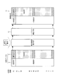
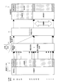
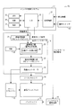
- FIG. 1 It is a control block diagram which shows the structure of the liquid crystal display device concerning one embodiment of this invention. It is a schematic diagram which shows the flow of a process of the image data in the daytime mode performed within the liquid crystal display device shown in FIG. Note that, on the right side of the figure, the display gradation in the liquid crystal display is schematically shown. It is a schematic diagram which shows the flow of a process of the image data in the night mode performed in the liquid crystal display device shown in FIG. Note that, on the right side of the figure, the display gradation in the liquid crystal display is schematically shown. It is a schematic diagram which shows an example of a structure of the image data in the image processing method of this invention. FIG.
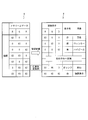
- FIG. 5 is a schematic diagram illustrating an example in which gradation conversion processing is performed on the image data illustrated in FIG. 4. It is a block diagram which shows the structure of the liquid crystal display device concerning the modification of the 1st Embodiment of this invention. It is a schematic diagram which shows an example of the flow of a process of the image data in the daytime mode performed within the liquid crystal display device concerning the 2nd Embodiment of this invention. Note that, on the right side of the figure, the display gradation in the liquid crystal display is schematically shown. It is a schematic diagram which shows an example of the flow of a process of the image data in the night mode performed within the liquid crystal display device concerning the 2nd Embodiment of this invention.
- the display gradation in the liquid crystal display is schematically shown.
- FIG. 16 is a schematic diagram illustrating a flow of image data processing in daytime mode performed in the liquid crystal display device illustrated in FIG. 15. Note that, on the right side of the figure, the display gradation in the liquid crystal display is schematically shown.
- FIG. 16 is a schematic diagram illustrating a flow of image data processing in the night mode performed in the liquid crystal display device illustrated in FIG. 15. Note that, on the right side of the figure, the display gradation in the liquid crystal display is schematically shown.
- FIGS. 1 to 5 An embodiment of the present invention will be described with reference to FIGS. 1 to 5 as follows. Note that the present invention is not limited to this.
- an in-vehicle liquid crystal display device will be described as an example.
- the in-vehicle liquid crystal display device is a device that is mounted on a vehicle and displays information from various sensors and in-vehicle devices, and can also be used as a car navigation system or a television.
- FIG. 1 shows a configuration of a liquid crystal display device 10 of the present embodiment.
- the liquid crystal display device 10 has a function of adjusting the brightness of an image displayed on the liquid crystal display in accordance with a change in ambient brightness (for example, so that the ambient brightness changes between day and night). have.
- the liquid crystal display device 10 includes, as main components, a liquid crystal display 11 (display panel), a backlight 12, a gate driver 13, a source driver 14, a backlight driving circuit 15, a display controller 16, an instrument panel, and the like.
- a control system 17 and an operation switch 18 are provided.
- the liquid crystal display 11 includes a liquid crystal layer between an active matrix substrate and a counter substrate.
- an MVA mode, a TN mode, an IPS mode, or the like can be adopted as a display mode of the liquid crystal display.
- the backlight 12 is provided on the back surface of the liquid crystal display 11 and irradiates the liquid crystal display with light.
- the backlight drive circuit 15 controls ON / OFF of the backlight 12 and irradiation brightness.
- the display controller 16 generates a drive signal for causing the liquid crystal display 11 to display an image based on the image data signal transmitted from the instrument panel control system 17.
- a gradation conversion unit 21 a gradation calculator 22 (image data identification unit, gradation conversion unit), a pseudo multi-gradation unit 23, a liquid crystal controller 24, and a ROM 25 are provided.
- the display controller 16 performs gradation conversion processing for reducing the luminance of the display image when the ambient brightness is reduced with respect to the image data (image signal) transmitted from the instrument panel control system 17.
- This gradation conversion processing is for displaying warning information for notifying a lighting state of a blinker, a half-door warning, an abnormality of devices in the vehicle, etc., among various information displayed on the liquid crystal display 11. It is not performed on image data (image data for warning display, first image data), but only for display data (second image data) other than warning information (this is called general display). Done. A specific processing flow in the display controller 16 will be described later.
- the instrument panel control system 17 is based on information from various sensors, position detectors, and other in-vehicle devices attached to the vehicle (collectively referred to as vehicle information) or information input from the operation switch 18. Then, an image data signal for displaying an image on the liquid crystal display 11 is generated.
- an AD conversion unit 31 a CPU 32, a ROM 33, a RAM 34, a data input / output unit (I / O) 35, and the like are provided.
- the AD converter 31 converts the input analog data (for example, vehicle information data, input data from the operation switch) into digital data, and transmits the digital data to the I / O 35.
- the I / O 35 receives external data via the AD conversion unit 31 and transmits it to the CPU 32 and various memories (ROM 33 and RAM 34) that are data processing units in the instrument panel control system 17. Data processed by the CPU 32 is transmitted to the external display controller 16 via the I / O 35. The data processed in the CPU 32 is once stored in the memory and then transmitted to the external display controller 16 via the I / O 35 at an appropriate timing.
- the liquid crystal display device 10 of the present embodiment has a function of adjusting the brightness of an image displayed on the liquid crystal display in accordance with a change in ambient brightness.
- the instrument panel control system 17 instructs the change of the image display mode based on the information on the ambient brightness detected by the illuminance sensor provided in the vehicle (that is, the day / night mode signal). Is generated.
- information about ambient brightness detected by an illuminance sensor provided in the vehicle is input to the instrument panel control system 17 as vehicle information.
- the CPU 32 in the system determines whether or not the ambient brightness is equal to or less than a predetermined value from the input vehicle information.
- a signal (day / night mode signal) instructing the daytime mode is generated.
- a signal (day / night mode signal) instructing the night mode is generated. This day / night mode signal is transmitted to the display controller 16 via the I / O 35 in the same manner as the image data.
- the switching between night mode instruction and daytime mode instruction in the day / night mode signal is not automatically performed based on the detection result of the illuminance sensor as described above, but the vehicle width lamp or headlight (headlight) is switched.
- There is also a method of performing based on ON / OFF of the lighting switch for example, changing to the night mode when the lighting switch is ON and changing to the daytime mode when the lighting switch is OFF).
- a specific image data (second image data (for example, data for general display))
- Data processing is performed in which gradation conversion processing is performed in accordance with changes in brightness, and pseudo multi-gradation processing is further performed on the data subjected to gradation conversion processing.
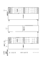
- FIG. 2 shows a flow of image data processing in the daytime mode performed in the liquid crystal display device 10 shown in FIG.
- FIG. 3 shows a flow of image data processing in the night mode performed in the liquid crystal display device 10 shown in FIG.
- 6-bit image data is displayed using a 6-bit driver
- the present invention is not necessarily limited to such a configuration, and can be applied to the case of using image data such as 4 bits, 8 bits, 10 bits, and a driver.
- the warning display is displayed using one of red, blue and orange.
- the gradation of the pixels of each color (red (R), green (G), blue (B)) constituting one pixel.
- the combinations of values are (63, 0, 0), (0, 0, 63), (63, 46, 0), respectively. Therefore, as shown in the drawing, the warning display image data b uses only the gradation values 0, 46, and 63, and other gradation values are not used. Note that the combination of gradation values for expressing the orange color described here is an example, and such gradation values are not necessarily limited.
- the image data D includes image data a (second image data) for general display and image data b (first image data) for warning display.
- image data a second image data
- image data b first image data
- 2 and 3 among the image data D transmitted from the instrument panel control system 17 to the display controller 16, the maximum gradation value 63 is not used for the image data a for general display, and 0 Consists of gradation values of up to 62.
- the image data b for warning display only the gradation values 0, 46 and 63 are used as described above, and the other gradation values are not used.
- the maximum gradation value 63 is not used in the image data a for general display but is used only in the image data b for warning display. That is, the gradation value 63 is a dedicated gradation value used only for the warning display data. Therefore, by detecting whether or not the maximum gradation value 63 is included in the data, the image data D for general display and the image data b for warning display are identified for the transmitted image data D. can do.
- the image data identification unit 26 provided in the gradation calculator 22 in the display controller 16 uses a general display for the display based on the transmitted image data D.
- the image data a and the warning display image data b are identified (image data identification step).
- the gradation conversion unit 21 converts the 6-bit image data into 8 bits in preparation for pseudo multi-gradation processing to be performed later. Is once converted into the image data.
- the image data D converted into 8-bit data by the gradation converter 21 is transmitted to the gradation calculator 22 (gradation converter).
- the image data identification unit 26 provided therein identifies the image data a for general display and the image data b for warning display with respect to the transmitted image data D. . Further, the gradation calculator 22 determines whether or not to perform gradation conversion processing for reducing the luminance of the display image, based on the day / night mode signal transmitted from the instrument panel control system 17.
- the transmitted day / night mode signal indicates the daytime mode
- gradation conversion processing and pseudo multi-gradation processing are not performed on the image data D (see FIG. 2).
- the gradation calculator 22 and the pseudo multi-gradation unit 23 do not perform the process of changing the gradation value, and the pseudo multi-gradation unit 23 re-converts the 8-bit image data into 6-bit image data.
- the image data D is transmitted to the liquid crystal controller 24.
- the liquid crystal display device 10 is not provided with a configuration for adjusting the luminance of the backlight 12 according to the ambient brightness, the backlight 12 emits light with 100% output.
- both general display and warning display are displayed on the screen using gradation values of 0 to 63 (see FIG. 2).
- the gradation calculator 22 moves the gradation value of the image data to the lower order in order to reduce the luminance of the display image. Perform value conversion processing.
- the gradation value conversion process described above is performed only on the image data a for general display in the transmitted image data D based on the identification result in the image data identification unit 26. (Tone conversion step).
- the upper gradation value is rounded down from the intermediate gradation to the low gradation with respect to the image data a for general display.
- Gradation conversion processing is performed using only the image. Thereby, only the image data a for general display can be processed to change the brightness of the display image according to the ambient brightness.
- gradation conversion processing for moving the gradation value of the image data to the lower order with respect to the image data b for general display is performed.
- the process of moving the gradation value of the image data to the lower level means that in the case of 6-bit image data, the maximum gradation is moved from 63 to 46, and accordingly, the other gradations
- the value is a process of moving to a lower gradation value.
- This gradation conversion processing can be performed using a conversion table stored in the ROM 25, for example.
- the image data b for general display subjected to the gradation value conversion processing by the gradation calculator 22 is subsequently subjected to pseudo multi-gradation processing by the pseudo multi-gradation unit 23 (pseudo multi-gradation processing). Gradation process).
- the pseudo multi-gradation unit 23 uses the well-known multi-gradation technique to process the image data in a pseudo multi-level so that the gray level jump caused by the gray level conversion performed by the gray level calculator 22 does not occur. To tune.
- Pseudo multi-gradation processing uses the property that the human eye recognizes luminance by averaging time and space, so that the number of gradations that can be expressed to the human eye with a limited number of gradations. This is a process that seems to have increased.
- the pseudo multi-gradation processing how large is the pixel area as a unit, or how the noise pattern is designed (that is, the noise pattern in each frame, the number of periodic frames, etc.) ), There are various methods such as FRC.
- the gradation conversion unit 21 converts 6-bit image data into 8-bit image data.
- the pseudo multi-gradation unit 23 separates the 8-bit image data into the upper 6 bits and the lower 2 bits using a 6-bit driver, and generates a 1-bit noise pattern based on the information of the lower 2 bits.
- the processing is performed by the processing procedure of creating and superimposing this noise pattern on each pixel (upper 6 bits + 1 bit noise pattern). As a result, the 8-bit image data is converted back to 6-bit image data.
- the image data D subjected to the above processing is input to the liquid crystal controller 24.
- the liquid crystal controller 24 generates a drive signal for displaying an image on the liquid crystal display 11 based on the input image data D, and transmits the drive signal to the gate driver 13 and the source driver 14.
- the liquid crystal display 11 performs image display based on various signals such as scanning signals and data signals transmitted from the gate driver 13 and the source driver 14.
- the warning is displayed on the screen using gradation values from 0 to 63.
- the general display uses a gradation value of 0 to 46, and the screen display is performed in a state having a gradation expressing ability of 64 gradations by the pseudo multi-gradation process (see FIG. 3). Since the liquid crystal display device 10 is not provided with a configuration for adjusting the irradiation luminance of the backlight 12 in accordance with the ambient brightness, the backlight 12 emits light with 100% output.
- the configuration in which the gradation conversion process and the pseudo multi-gradation process are not performed on the image data D for the purpose of brightness adjustment is given as an example.
- the invention is not limited to such a configuration.
- a gradation conversion process for changing the gradation value of the image data is performed, and the gradation number associated therewith is changed.
- a pseudo multi-gradation process is performed to compensate for the decrease.
- FIG. 12 shows the configuration of the liquid crystal display device 110.
- the liquid crystal display device 110 includes, as main components, a liquid crystal display 111, a backlight 112, a gate driver 113, a source driver 114, a backlight driving circuit 115, a liquid crystal controller 124, an instrument panel control system 117, And an operation switch 118.
- an AD conversion unit 131 In the instrument panel control system 117, an AD conversion unit 131, a CPU 132, a ROM 133, a RAM 134, a data input / output unit (I / O) 135, and the like are provided.
- the conventional example 1 is not provided with a display controller for performing gradation conversion processing of image data according to ambient brightness.
- the brightness of the display image is adjusted not by adjusting the brightness of the display image by the gradation conversion process, but by changing the illumination brightness of the backlight 112.
- FIG. 13 shows a flow of image data processing in the daytime mode performed in the liquid crystal display device 110 shown in FIG.
- FIG. 14 shows a flow of image data processing in the night mode performed in the liquid crystal display device 110 shown in FIG.
- the image data D is composed of image data a for general display and image data b for warning display.
- the brightness of the backlight 112 of the liquid crystal display device 110 is controlled, for example, as follows between daytime and nighttime.
- Information related to ambient brightness detected by the illuminance sensor provided in the vehicle is input to the instrument panel control system 117 as vehicle information. Then, the CPU 132 in the system determines whether or not the ambient brightness is equal to or less than a predetermined value from the input vehicle information. Here, when it is determined that the ambient brightness is higher than a predetermined value, a signal (backlight control signal) instructing the daytime mode is generated. On the other hand, when it is determined that the ambient brightness is equal to or less than a predetermined value, a signal (backlight control signal) instructing the night mode is generated. This backlight control signal is transmitted to the backlight drive circuit 115 via the I / O 135.
- Switching between night mode instruction and daytime mode instruction in the backlight control signal is performed automatically based on the detection result of the illuminance sensor as described above, as well as vehicle width lamps or headlamps (headlights).
- There is also a method of performing on the basis of ON / OFF of the lighting switch for example, changing to the night mode when the lighting switch is ON and changing to the day mode when the lighting switch is OFF).
- the screen display in the daytime mode and the nighttime mode is as follows.
- the brightness of the backlight is illuminated at 100%.
- the gradation value is 63, both the general display and the warning display have the maximum luminance.
- the brightness of the backlight is reduced to 50%. Even when an image is displayed, the brightness of the screen display shown on the right side is about half that of the daytime mode.
- the brightness of the entire display screen is adjusted by changing the brightness of the backlight according to the ambient brightness.
- the brightness of the entire screen changes uniformly, so if the entire display screen is darkened at night, etc., the warning display will also be darkened, making it difficult for the driver to recognize it. There is a problem that it ends up.
- FIG. 15 shows a configuration of an in-vehicle liquid crystal display device 150 according to Conventional Example 2.
- FIG. 16 shows a flow of image data processing in the daytime mode performed in the liquid crystal display device 150 shown in FIG.
- FIG. 17 shows a flow of image data processing in the night mode performed in the liquid crystal display device 150 shown in FIG.
- the liquid crystal display device 150 includes, as main components, a liquid crystal display 111, a backlight 112, a gate driver 113, a source driver 114, a backlight driving circuit 115, a display controller 116, an instrument panel control system 117, And an operation switch 118.
- an AD conversion unit 131 In the instrument panel control system 117, an AD conversion unit 131, a CPU 132, a ROM 133, a RAM 134, a data input / output unit (I / O) 135, and the like are provided.
- the display controller 116 is provided with a gradation calculator 122, a ROM 125, and a liquid crystal controller 124.
- the gradation calculator 122 and the ROM 125 are configured not in the conventional example 1.
- the gradation calculator 122 cuts off the upper gradation value and uses only the intermediate gradation to the low gradation with respect to the image data for general display. Tone conversion processing is performed. As a result, only the image data for general display is subjected to processing for changing the brightness of the display image in accordance with the ambient brightness.
- Information related to ambient brightness detected by the illuminance sensor provided in the vehicle is input to the instrument panel control system 117 as vehicle information. Then, the CPU 132 in the system determines whether or not the ambient brightness is equal to or less than a predetermined value from the input vehicle information. Here, when it is determined that the ambient brightness is higher than a predetermined value, a signal (day / night mode signal) instructing the daytime mode is generated. On the other hand, when it is determined that the ambient brightness is equal to or less than a predetermined value, a signal (day / night mode signal) instructing the night mode is generated. This day / night mode signal is transmitted to the display controller 116 via the I / O 135.
- the switching between night mode instruction and daytime mode instruction in the day / night mode signal is not automatically performed based on the detection result of the illuminance sensor as described above, but the vehicle width lamp or headlight (headlight) is switched.
- There is also a method of performing based on ON / OFF of the lighting switch for example, changing to the night mode when the lighting switch is ON and changing to the daytime mode when the lighting switch is OFF).
- the CPU 132 of the instrument panel control system 117 determines the type of various input display information, and displays warning information for notifying the lighting state of the blinker, a half-door warning, an abnormality in the equipment in the vehicle, and the like.
- the gradation calculator 122 of the display controller 116 when the daytime mode is instructed by the day / night mode signal transmitted from the instrument panel control system 117, the gradation value conversion processing is not performed, so the general display and the warning display are performed. In both cases, screen display is performed using gradation values from 0 to 63 (see FIG. 16).
- the image data for display other than warning display (that is, general display) is displayed on the basis of the warning identification signal.
- a tone value conversion process is performed (see FIG. 17).
- the maximum gradation is changed from 63 to 46 using a conversion table stored in the ROM 125. Note that since the tone conversion process is not performed for the warning display, the display is performed using the maximum tone value 63 as in the daytime mode (see FIG. 17).
- the brightness of the display screen is changed between day and night by changing the gradation value to be used without changing the luminance of the backlight.
- the gradation conversion process can be performed or not performed depending on the type of information to be displayed, so that the warning display can be displayed without reducing the luminance at night as described above. .
- a dedicated gradation value for example, 6
- a maximum gradation value 63 in bit data is provided.
- the warning display data and the general display data can be easily identified by not using the dedicated gradation value for the general display image data.
- gradation conversion processing of image data for general display can be easily performed.
- the warning display data and the general display data can be easily identified under the limitation of the predetermined number of bits without causing an increase in circuit scale accompanying an increase in the number of bits of the image data. be able to.
- the gradation value is converted so that the gradation value is moved downward only for the image data for general display. Can change the brightness of the display image in accordance with the change in brightness, and can maintain a high display luminance when displaying specific information such as a warning display.
- warning display data and the general display data can be easily identified as described above, only the general display data is subjected to image processing for suppressing deterioration in image quality. Can do.
- pseudo multi-gradation processing only on the data for general display, it is possible to suppress a decrease in gradation expression due to the unused upper gradation value being unused.
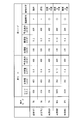
- FIG. 11 in the configuration of the present embodiment and the conventional examples 1 and 2, the general display white luminance, the general display black luminance, the warning display luminance, and the like in each mode (daytime mode and nighttime mode) were measured. Results are shown.
- the case where the display mode of the liquid crystal display is the TN mode is shown as the present invention A
- the case of the MVA mode is shown as the present invention B
- the case of the IPS mode is shown as the present invention C.
- the contrast is white luminance / black luminance.
- the gradation display indicates whether or not gradation representation with 0 to 64 gradations is possible in 8-bit image data, and ⁇ means that gradation representation is possible. , X means that gradation expression is impossible.
- the warning determination indicates whether the image data for general display and the image data for warning display can be easily identified.
- the white luminance can be reduced as compared with the day mode.
- the pseudo multi-gradation processing is not performed, gradation expression with 0 to 64 gradations is impossible.
- the circuit configuration for determining the image data for warning display is complicated.
- gradation representation with 0 to 64 gradations is possible by performing pseudo multi-gradation processing. Further, by setting the maximum gradation (that is, gradation value 63) to a gradation value dedicated to the warning display image data, the warning display image data can be easily identified.
- the maximum gradation value (for example, image data including the gradation value 63) is uniformly gradation using a conversion table or the like stored in the ROM 25.
- the image data identification unit 26 may not be provided.
- the present invention A (TN mode) has a higher black luminance than 0.8 in comparison with other display modes. Floating will occur.
- a display mode such as the present invention B (MVA mode) or the present invention C (IPS mode)
- the black luminance can be lowered. Therefore, the liquid crystal display device of the present invention is preferably applied to a liquid crystal display device including an MVA mode or IPS mode liquid crystal display, and more preferably applied to a liquid crystal display device including an MVA mode liquid crystal display.
- Modification of Embodiment 1 a modification of the present embodiment will be described.
- This modification uses the fact that the maximum gradation value 63 is exclusively used for image data for warning display, and uses the color (red (R), green (G), blue (B)) constituting one pixel.
- RGB red
- G green
- B blue
- FIG. 4 shows a data structure of the image data D generated in the instrument panel control system 17 when performing the image processing of the modified example.
- the maximum gradation value 63 of each RGB color is the gradation used for the warning display image data
- the gradation value 0 to 62 of each RGB color is used for the general display image data. Gradation.
- FIG. 5 shows an example in which gradation conversion processing is performed by the gradation calculator 22 for the image data shown in FIG.
- Table A in FIG. 5 shows combinations of one pixel of image data for warning display generated in the CPU 32 in the instrument panel control system 17 and stored in the memory (video memory).
- Table B in FIG. 5 shows combinations of gradation values after gradation conversion processing is performed by the gradation calculator 22.
- each RGB color has a gradation value of 0 or 63.
- the warning display can be displayed in seven colors.
- the color can be changed according to the type of warning.
- the tables A and B in FIG. 5 may be stored in the ROM 25 as conversion tables.
- FIG. 6 shows a configuration of a liquid crystal display device 10a according to this modification.
- the configuration of the liquid crystal display device 10a is different from the liquid crystal display device 10 only in that the image data identification unit 26 is not provided in the gradation calculator 22, and the other configuration is the liquid crystal display device shown in FIG. 10 is the same. Therefore, detailed description of the configuration is omitted.
- the gradation value 63 that is the maximum gradation value is the gradation dedicated to the warning display.
- the gradation value 0 that is the minimum gradation value is the gradation dedicated to the warning display. Even in this case, the same effect can be obtained by performing the same process as described above.
- the gradation value 62 that is the maximum gradation in the image data for general display (that is, the gradation value of (maximum gradation value-1)) is set to have the same luminance as 63 gradations. Further gradation conversion processing may be performed in the gradation calculator 22. According to this, general display can be performed without sacrificing luminance in the daytime mode.
- the gradation value 1 that is, the gradation value of (minimum gradation value + 1) which is the minimum gradation in the image data for general display is used. If the same processing is performed, the same effect can be obtained.
- the maximum gradation value and the gradation value of (maximum gradation value-1) are used as dedicated gradation values used only for the image data for warning display. Is used to convert image data including a gradation value of (maximum gradation value ⁇ 1) into a gradation value for displaying orange.
- the configuration of the liquid crystal display device according to the present embodiment is substantially the same as the configuration of the liquid crystal display device 10 shown in FIG. 1, and therefore will be described with reference to FIG.
- the image data identification unit 26 is not necessary because the image data is identified together with the gradation conversion processing in the gradation calculator 22.
- FIG. 7 shows an example of the flow of image data processing in the daytime mode performed in the liquid crystal display device 10 according to the present embodiment. Also, an example of the flow of image data processing in the night mode performed in the liquid crystal display device 10 according to the present embodiment will be shown.
- the image data D includes image data a (second image data) for general display and image data b (first image data) for warning display.
- image data a for general display has a maximum gradation value 63 and (maximum gradation value).
- -1) 62 is not used and is composed of gradation values from 0 to 61.
- the image data b for warning display only the gradation values 0, 62, and 63 are used, and the other gradation values are not used.
- the gradation converting unit 21 When such image data D is transmitted from the I / O 35 of the instrument panel control system 17 to the gradation converting unit 21, the gradation converting unit 21 prepares for 6-bit in preparation for pseudo multi-gradation processing to be performed later. Is once converted into 8-bit image data.
- the image data D converted into 8-bit data by the gradation conversion unit 21 is transmitted to the gradation calculator 22 (image data identification unit, gradation conversion unit). Based on the day / night mode signal transmitted from the instrument panel control system 17, the gradation calculator 22 determines whether or not to perform gradation conversion processing for reducing the luminance of the display image, as in the first embodiment. To do.
- the gradation calculator 22 identifies the data including the gradation value 63 as image data for warning display, and outputs the data as it is without performing gradation conversion processing. Further, the image data including the gradation value 62 is also identified as image data for warning display, and gradation conversion for displaying orange using a conversion table stored in the ROM 25 is performed. . The other image data is identified as image data for general display, and gradation conversion is performed to move it to a lower gradation. Since the subsequent processing is the same as that of the first embodiment, description thereof is omitted.
- the gradation calculator 22 performs the image processing to be performed on each image data together with the discrimination between the image data a for general display and the image data b for warning display. It can be carried out. That is, the gradation calculator 22 functions as both image data identification and a gradation conversion unit. Thereby, image processing can be performed with a simpler configuration.
- the maximum gradation value and the gradation value of (maximum gradation value-1) are two.
- the dedicated gradation value includes a maximum gradation value, a gradation value of (maximum gradation value ⁇ 1),..., And a gradation value of (maximum gradation value ⁇ n) (where n (N + 1) number of gradation values can be used. Then, if the image data including each of the dedicated gradation values is converted into gradation values for displaying any color, more types of colors can be used for the image data for warning display. it can.
- the dedicated gradation the minimum gradation value, the gradation value of (minimum gradation value + 1),..., And the gradation value of (minimum gradation value + n) (where n is 1 to 1) Any integer up to 10) may be used.
- image processing can be performed in the same manner as in the case of the maximum gradation value.
- the present invention is applied to a display device that does not have a function of dimming the backlight.
- the present invention is not limited to this and has a backlight dimming function.
- the present invention may be applied to a display device.
- FIG. 9 shows the configuration of the liquid crystal display device 50 according to the present embodiment.
- the backlight drive circuit 15 changes the irradiation luminance of the backlight 12 based on the backlight control signal transmitted from the instrument panel control system 17.
- the brightness of the backlight 12 of the liquid crystal display device 50 is controlled, for example, between daytime and nighttime as follows.
- Information related to ambient brightness detected by the illuminance sensor provided in the vehicle is input to the instrument panel control system 17 as vehicle information. Then, the CPU 32 in the system determines whether or not the ambient brightness is equal to or less than a predetermined value from the input vehicle information. Here, when it is determined that the ambient brightness is higher than a predetermined value, a signal (backlight control signal) instructing the daytime mode is generated. On the other hand, when it is determined that the ambient brightness is equal to or less than a predetermined value, a signal (backlight control signal) instructing the night mode is generated. This backlight control signal is transmitted to the backlight drive circuit 15 via the I / O 35.
- the switching between night mode instruction and daytime mode instruction in the day / night mode signal is not automatically performed based on the detection result of the illuminance sensor as described above, but the vehicle width lamp or headlight (headlight) is switched.
- There is also a method of performing based on ON / OFF of the lighting switch for example, changing to the night mode when the lighting switch is ON and changing to the daytime mode when the lighting switch is OFF).
- the backlight control signal is a signal indicating the daytime mode
- the backlight Since the luminance is 100%, a brighter image is displayed.
- the brightness of the backlight is reduced to, for example, 50%. Even in this case, the brightness of the screen display shown on the right side is about half that of the daytime mode. Thereby, it is possible to further reduce the luminance of an image in a low gradation region such as black display.
- FIG. 10 shows the configuration of the liquid crystal display device 60 of the present embodiment.
- each processing unit performed in preparation for the pseudo multi-gradation processing that is, gradation conversion that performs conversion processing from 6-bit image data to 8-bit image data.
- a unit 41 and a gradation calculator 42 for performing gradation value conversion processing for moving the gradation value of the image data to the lower order in order to reduce the luminance of the display image are provided. It has been.
- a ROM 33b used when the gradation calculator 42 performs gradation conversion is also provided in the instrument panel control system 17.
- ROM 33a for storing graphic data
- ROM 33b for gradation conversion.
- the image data for warning display is converted based on the information in the ROM 33b as in the second embodiment.
- the gradation calculator 42 reads the graphic data to be displayed on the liquid crystal display device 60 from the ROM 33a, determines whether the graphic data is a warning display or a general display at the read stage, and further, based on the day / night mode signal, The gradation is calculated based on the table conversion data in the ROM 33b. Then, the gradation calculator 42 performs gradation conversion on all graphic data and temporarily writes it in the RAM 34.
- the data written in the RAM 34 is read from the RAM 34 and transmitted to the display controller 16 as in the case of the conventional graphic display.
- the data transmitted to the display controller 16 is subjected to pseudo multi-gradation processing and converted into an actual liquid crystal display signal to realize display.
- the processing performed in each block constituting the liquid crystal display device 60 is the same as that of the liquid crystal display device 10 shown in FIG. 1, the description thereof is omitted here. Further, in the liquid crystal display device 60 shown in FIG. 10, the image data identification unit is not shown, but the image data identification unit is provided in the gradation calculator 41. Here, the image data for warning display and the general display Are identified.
- the graphic ROM 33a and the gradation conversion ROM 33b can be integrated in the instrument panel control system 17, so that the configuration of the apparatus is further simplified. Can do.
- the pseudo multi-gradation unit 23 can also be configured to be included in the instrument panel control system 17.
- the pseudo multi-gradation processing is related to the drive control of the liquid crystal, it is preferable to integrate the liquid crystal controller and include it in the display controller in order to simplify the configuration.
- the first image data is configured to include a dedicated gradation value used only for the first image data.
- An image data identification unit for identifying whether the image data is the first image data or the second image data by determining whether a dedicated gradation value is included in the image data;
- a gradation conversion unit that converts the gradation value of the image data in order to reduce the luminance of the display image when the surrounding brightness decreases, and the gradation conversion unit is configured to A gradation conversion process for reducing the luminance of the display image is performed only on the image data identified as the second image data.
- the first image data includes a dedicated gradation value used only for the first image data.
- the image processing method identifies whether the image data is the first image data or the second image data by determining whether the dedicated gradation value is included in the image data.
- a gradation conversion process for reducing the luminance of the display image is performed only on the image data identified as the second image data in the image data identification step.
- the first image data and the second image data can be easily identified, only the second image data has an image quality such as a pseudo multi-gradation process.
- Image processing for suppressing the reduction can be performed. For this reason, for example, it is possible to suppress deterioration in image quality such as general display displayed by the second image data, and to maintain high display brightness when displaying information of higher importance such as warning display.
- a liquid crystal display device that does not impair the performance can be realized.
- the liquid crystal display device of the present invention can be suitably used as a vehicle-mounted liquid crystal display device.
Landscapes
- Engineering & Computer Science (AREA)
- Chemical & Material Sciences (AREA)
- Crystallography & Structural Chemistry (AREA)
- Physics & Mathematics (AREA)
- Computer Hardware Design (AREA)
- General Physics & Mathematics (AREA)
- Theoretical Computer Science (AREA)
- Control Of Indicators Other Than Cathode Ray Tubes (AREA)
- Controls And Circuits For Display Device (AREA)
Abstract
L'invention porte sur un dispositif d'affichage à cristaux liquides (10) qui utilise un signal d'image et qui comprend des données d'image pour affichage d'alerte (premières données d'image) et des données d'image pour affichage général (deuxièmes données d'image), afin d'afficher une image sur un panneau d'affichage. Les données d'image pour l'affichage d'alerte comprennent une valeur d'échelle de gris exclusive qui n'est utilisée que pour les données d'image pour affichage d'alerte. Le dispositif d'affichage à cristaux liquides (10) comprend une partie d'identification de données d'image (26) qui détermine si la valeur d'échelle de gris exclusive est ou non incluse dans des données d'image, de façon à identifier le type de données d'image; et un calculateur d'échelle de gris (22) (partie de conversion d'échelle de gris) qui effectue une conversion de la valeur d'échelle de gris des données d'image de façon à réduire la luminosité de l'image affichée lorsque la luminosité ambiante diminue.
Priority Applications (2)
| Application Number | Priority Date | Filing Date | Title |
|---|---|---|---|
| US12/735,417 US20110050738A1 (en) | 2008-02-27 | 2008-10-29 | Liquid crystal display device and image processing method in liquid crystal display device |
| CN200880125095.2A CN101911174B (zh) | 2008-02-27 | 2008-10-29 | 液晶显示装置及液晶显示装置中的图像处理方法 |
Applications Claiming Priority (2)
| Application Number | Priority Date | Filing Date | Title |
|---|---|---|---|
| JP2008046871 | 2008-02-27 | ||
| JP2008-046871 | 2008-02-27 |
Publications (1)
| Publication Number | Publication Date |
|---|---|
| WO2009107277A1 true WO2009107277A1 (fr) | 2009-09-03 |
Family
ID=41015686
Family Applications (1)
| Application Number | Title | Priority Date | Filing Date |
|---|---|---|---|
| PCT/JP2008/069669 Ceased WO2009107277A1 (fr) | 2008-02-27 | 2008-10-29 | Dispositif d'affichage à cristaux liquides et procédé de traitement d'images dans un dispositif d'affichage à cristaux liquides |
Country Status (3)
| Country | Link |
|---|---|
| US (1) | US20110050738A1 (fr) |
| CN (1) | CN101911174B (fr) |
| WO (1) | WO2009107277A1 (fr) |
Cited By (2)
| Publication number | Priority date | Publication date | Assignee | Title |
|---|---|---|---|---|
| US20120249619A1 (en) * | 2009-12-28 | 2012-10-04 | Sharp Kabushiki Kaisha | Display device |
| WO2018116468A1 (fr) * | 2016-12-22 | 2018-06-28 | マクセル株式会社 | Dispositif d'affichage vidéo par projection et procédé d'affichage vidéo associé |
Families Citing this family (19)
| Publication number | Priority date | Publication date | Assignee | Title |
|---|---|---|---|---|
| TWI386910B (zh) * | 2009-02-23 | 2013-02-21 | Wistron Corp | 顯示裝置及其亮度調整方法 |
| BR112012013002B1 (pt) * | 2009-11-30 | 2019-08-27 | Eaton Corp | sistema de painel de controle |
| KR102047433B1 (ko) | 2011-09-23 | 2019-12-04 | 매뉴팩처링 리소시스 인터내셔널 인코포레이티드 | 디스플레이 특성들의 환경 적응을 위한 시스템 및 방법 |
| EP2779149B1 (fr) * | 2013-03-15 | 2019-05-08 | Volvo Car Corporation | Procédé et système de réglage d'intensité pour ajuster l'intensité d'un affichage de véhicule |
| JP6415022B2 (ja) * | 2013-05-08 | 2018-10-31 | キヤノン株式会社 | 画像処理装置、画像処理方法及びプログラム |
| KR101500238B1 (ko) * | 2013-12-23 | 2015-03-06 | 현대자동차주식회사 | 차량용 헤드업 디스플레이 조명 표시 방법 |
| US10593255B2 (en) | 2015-05-14 | 2020-03-17 | Manufacturing Resources International, Inc. | Electronic display with environmental adaptation of display characteristics based on location |
| US10321549B2 (en) | 2015-05-14 | 2019-06-11 | Manufacturing Resources International, Inc. | Display brightness control based on location data |
| US10607520B2 (en) * | 2015-05-14 | 2020-03-31 | Manufacturing Resources International, Inc. | Method for environmental adaptation of display characteristics based on location |
| WO2018009917A1 (fr) | 2016-07-08 | 2018-01-11 | Manufacturing Resources International, Inc. | Commande de luminosité d'affichage sur la base de données de dispositif de capture d'image |
| US9898971B1 (en) * | 2016-08-10 | 2018-02-20 | Caterpillar Inc. | System, method, and apparatus to selectively control brightness of liquid crystal display |
| CN106847150B (zh) * | 2017-01-04 | 2020-11-13 | 捷开通讯(深圳)有限公司 | 调节显示屏亮度的装置及方法 |
| KR102552137B1 (ko) * | 2018-01-22 | 2023-07-07 | 삼성디스플레이 주식회사 | 표시 장치 및 이의 구동 방법 |
| US10578658B2 (en) | 2018-05-07 | 2020-03-03 | Manufacturing Resources International, Inc. | System and method for measuring power consumption of an electronic display assembly |
| US10782276B2 (en) | 2018-06-14 | 2020-09-22 | Manufacturing Resources International, Inc. | System and method for detecting gas recirculation or airway occlusion |
| US11526044B2 (en) | 2020-03-27 | 2022-12-13 | Manufacturing Resources International, Inc. | Display unit with orientation based operation |
| US12105370B2 (en) | 2021-03-15 | 2024-10-01 | Manufacturing Resources International, Inc. | Fan control for electronic display assemblies |
| US12022635B2 (en) | 2021-03-15 | 2024-06-25 | Manufacturing Resources International, Inc. | Fan control for electronic display assemblies |
| US12027132B1 (en) | 2023-06-27 | 2024-07-02 | Manufacturing Resources International, Inc. | Display units with automated power governing |
Citations (6)
| Publication number | Priority date | Publication date | Assignee | Title |
|---|---|---|---|---|
| JP2000292791A (ja) * | 1999-02-04 | 2000-10-20 | Sharp Corp | 液晶表示素子およびプラズマアドレス型液晶表示装置 |
| JP2005041355A (ja) * | 2003-07-23 | 2005-02-17 | Nippon Seiki Co Ltd | 車両用表示装置及びその表示方法 |
| JP2006268245A (ja) * | 2005-03-23 | 2006-10-05 | Casio Hitachi Mobile Communications Co Ltd | 情報取得装置、および、プログラム |
| JP2007091030A (ja) * | 2005-09-28 | 2007-04-12 | Denso Corp | 車載表示装置 |
| JP2007114035A (ja) * | 2005-10-20 | 2007-05-10 | Denso Corp | 車両用表示装置 |
| JP2008039816A (ja) * | 2006-08-01 | 2008-02-21 | Sharp Corp | 表示装置 |
Family Cites Families (19)
| Publication number | Priority date | Publication date | Assignee | Title |
|---|---|---|---|---|
| US5610586A (en) * | 1993-06-24 | 1997-03-11 | Cart Watch, Inc. | Golf cart control and monitoring apparatus and system |
| US5440428A (en) * | 1993-09-30 | 1995-08-08 | Hughes Aircraft Company | Automotive instrument 3-D virtual image display |
| JP3688751B2 (ja) * | 1995-04-13 | 2005-08-31 | シャープ株式会社 | 情報表示装置 |
| US6124647A (en) * | 1998-12-16 | 2000-09-26 | Donnelly Corporation | Information display in a rearview mirror |
| US6259981B1 (en) * | 1999-06-17 | 2001-07-10 | Thomas J. Wilcosky | Caution/warning system for displaying system malfunctions/faults in a night-time viewing mode |
| DE19944067A1 (de) * | 1999-09-14 | 2001-03-15 | Mannesmann Vdo Ag | Verfahren zur Anzeige von Primär- und Sekundärinformationen |
| JP3763397B2 (ja) * | 2000-03-24 | 2006-04-05 | シャープ株式会社 | 画像処理装置、画像表示装置、パーソナルコンピュータ、画像処理方法 |
| US6507286B2 (en) * | 2000-12-29 | 2003-01-14 | Visteon Global Technologies, Inc. | Luminance control of automotive displays using an ambient light sensor |
| US20030034902A1 (en) * | 2001-08-17 | 2003-02-20 | Dickau John Eugene | Automatic pilot control system (ACS) for GLOC and ILOC, with aircraft following systems |
| KR100819111B1 (ko) * | 2002-07-08 | 2008-04-04 | 이노베이티브 솔루션즈 앤드 서포트 인코포레이티드 | 항공기의 다기능 평면 패널 디스플레이 상에서 승무원에게 시인성 및 데이터의 동시 분석성을 용이하게 하는 방법 및 장치 |
| JP3988575B2 (ja) * | 2002-08-09 | 2007-10-10 | 株式会社デンソー | フルカラー表示装置 |
| TWI227768B (en) * | 2002-10-29 | 2005-02-11 | Fujitsu Display Tech | Illumination device and liquid crystal display device using the same |
| JP4390483B2 (ja) * | 2003-06-19 | 2009-12-24 | シャープ株式会社 | 液晶中間調表示方法及びその方法を用いた液晶表示装置 |
| JP2007033864A (ja) * | 2005-07-27 | 2007-02-08 | Mitsubishi Electric Corp | 画像処理回路及び画像処理方法 |
| US7966123B2 (en) * | 2005-09-28 | 2011-06-21 | Denso Corporation | Display device and method for vehicle |
| KR100760943B1 (ko) * | 2006-01-25 | 2007-09-21 | 엘지.필립스 엘시디 주식회사 | 모바일용 표시장치의 구동장치 및 구동방법 |
| JP5135990B2 (ja) * | 2006-11-27 | 2013-02-06 | 株式会社デンソー | 車両用表示装置 |
| US7826969B2 (en) * | 2006-12-21 | 2010-11-02 | Deere & Company | Determining position of a vehicle with reference to a landmark |
| JP2008158732A (ja) * | 2006-12-22 | 2008-07-10 | Matsushita Electric Ind Co Ltd | 画像処理装置 |
-
2008
- 2008-10-29 WO PCT/JP2008/069669 patent/WO2009107277A1/fr not_active Ceased
- 2008-10-29 US US12/735,417 patent/US20110050738A1/en not_active Abandoned
- 2008-10-29 CN CN200880125095.2A patent/CN101911174B/zh not_active Expired - Fee Related
Patent Citations (6)
| Publication number | Priority date | Publication date | Assignee | Title |
|---|---|---|---|---|
| JP2000292791A (ja) * | 1999-02-04 | 2000-10-20 | Sharp Corp | 液晶表示素子およびプラズマアドレス型液晶表示装置 |
| JP2005041355A (ja) * | 2003-07-23 | 2005-02-17 | Nippon Seiki Co Ltd | 車両用表示装置及びその表示方法 |
| JP2006268245A (ja) * | 2005-03-23 | 2006-10-05 | Casio Hitachi Mobile Communications Co Ltd | 情報取得装置、および、プログラム |
| JP2007091030A (ja) * | 2005-09-28 | 2007-04-12 | Denso Corp | 車載表示装置 |
| JP2007114035A (ja) * | 2005-10-20 | 2007-05-10 | Denso Corp | 車両用表示装置 |
| JP2008039816A (ja) * | 2006-08-01 | 2008-02-21 | Sharp Corp | 表示装置 |
Cited By (4)
| Publication number | Priority date | Publication date | Assignee | Title |
|---|---|---|---|---|
| US20120249619A1 (en) * | 2009-12-28 | 2012-10-04 | Sharp Kabushiki Kaisha | Display device |
| WO2018116468A1 (fr) * | 2016-12-22 | 2018-06-28 | マクセル株式会社 | Dispositif d'affichage vidéo par projection et procédé d'affichage vidéo associé |
| JPWO2018116468A1 (ja) * | 2016-12-22 | 2019-10-24 | マクセル株式会社 | 投写型映像表示装置とそのための映像表示方法 |
| US10887564B2 (en) | 2016-12-22 | 2021-01-05 | Maxell, Ltd. | Projection video display apparatus and video display method therefor |
Also Published As
| Publication number | Publication date |
|---|---|
| CN101911174B (zh) | 2013-06-26 |
| US20110050738A1 (en) | 2011-03-03 |
| CN101911174A (zh) | 2010-12-08 |
Similar Documents
| Publication | Publication Date | Title |
|---|---|---|
| CN101911174B (zh) | 液晶显示装置及液晶显示装置中的图像处理方法 | |
| KR101203349B1 (ko) | 차량용 표시 장치 | |
| JP6481273B2 (ja) | 車両用表示装置 | |
| JP5056831B2 (ja) | ヘッドアップディスプレイ装置 | |
| JP2010091816A (ja) | 表示装置 | |
| JP2018185413A (ja) | 自動二輪車の表示装置 | |
| JP2012198464A (ja) | 表示制御装置、画像表示システム及び表示制御方法 | |
| JP4864852B2 (ja) | 車両用表示装置 | |
| JP2007522007A (ja) | 表示装置、表示装置の制御方法、表示装置の制御プログラムおよび記録媒体 | |
| WO2009110137A1 (fr) | Dispositif d'affichage à cristaux liquides et procédé de commande de dispositif d'affichage à cristaux liquides | |
| JP2019028102A (ja) | 画像表示装置および画像表示方法 | |
| JP4702537B2 (ja) | 車載表示装置 | |
| JP2019034640A (ja) | 車両用灯具 | |
| JP5477451B2 (ja) | 車両用表示装置 | |
| JP2005343332A (ja) | 車載用dvdシステム | |
| EP2784579A1 (fr) | Dispositif d'affichage tête haute et procédé d'affichage d'un tel dispositif | |
| JP2007249085A (ja) | 液晶表示装置及びその駆動方法 | |
| US12230226B2 (en) | Power dissipation for full area local dimming (FALD) display | |
| JP2007033980A (ja) | 液晶表示装置 | |
| KR20070075009A (ko) | 표시 장치 및 이의 구동 방법 |
Legal Events
| Date | Code | Title | Description |
|---|---|---|---|
| WWE | Wipo information: entry into national phase |
Ref document number: 200880125095.2 Country of ref document: CN |
|
| 121 | Ep: the epo has been informed by wipo that ep was designated in this application |
Ref document number: 08872845 Country of ref document: EP Kind code of ref document: A1 |
|
| NENP | Non-entry into the national phase |
Ref country code: DE |
|
| 122 | Ep: pct application non-entry in european phase |
Ref document number: 08872845 Country of ref document: EP Kind code of ref document: A1 |
|
| NENP | Non-entry into the national phase |
Ref country code: JP |