WO2009107336A1 - 充電装置及び充電方法 - Google Patents
充電装置及び充電方法 Download PDFInfo
- Publication number
- WO2009107336A1 WO2009107336A1 PCT/JP2009/000595 JP2009000595W WO2009107336A1 WO 2009107336 A1 WO2009107336 A1 WO 2009107336A1 JP 2009000595 W JP2009000595 W JP 2009000595W WO 2009107336 A1 WO2009107336 A1 WO 2009107336A1
- Authority
- WO
- WIPO (PCT)
- Prior art keywords
- charging
- battery
- secondary battery
- discharge
- amount
- Prior art date
- Legal status (The legal status is an assumption and is not a legal conclusion. Google has not performed a legal analysis and makes no representation as to the accuracy of the status listed.)
- Ceased
Links
Images
Classifications
-
- H—ELECTRICITY
- H02—GENERATION; CONVERSION OR DISTRIBUTION OF ELECTRIC POWER
- H02J—ELECTRIC POWER NETWORKS; CIRCUIT ARRANGEMENTS OR SYSTEMS FOR SUPPLYING OR DISTRIBUTING ELECTRIC POWER; SYSTEMS FOR STORING ELECTRIC ENERGY
- H02J7/00—Circuit arrangements for charging or discharging batteries or for supplying loads from batteries
- H02J7/60—Circuit arrangements for charging or discharging batteries or for supplying loads from batteries including safety or protection arrangements
- H02J7/61—Circuit arrangements for charging or discharging batteries or for supplying loads from batteries including safety or protection arrangements against overcharge
-
- H—ELECTRICITY
- H01—ELECTRIC ELEMENTS
- H01M—PROCESSES OR MEANS, e.g. BATTERIES, FOR THE DIRECT CONVERSION OF CHEMICAL ENERGY INTO ELECTRICAL ENERGY
- H01M10/00—Secondary cells; Manufacture thereof
- H01M10/42—Methods or arrangements for servicing or maintenance of secondary cells or secondary half-cells
- H01M10/44—Methods for charging or discharging
- H01M10/441—Methods for charging or discharging for several batteries or cells simultaneously or sequentially
-
- H—ELECTRICITY
- H01—ELECTRIC ELEMENTS
- H01M—PROCESSES OR MEANS, e.g. BATTERIES, FOR THE DIRECT CONVERSION OF CHEMICAL ENERGY INTO ELECTRICAL ENERGY
- H01M10/00—Secondary cells; Manufacture thereof
- H01M10/42—Methods or arrangements for servicing or maintenance of secondary cells or secondary half-cells
- H01M10/425—Structural combination with electronic components, e.g. electronic circuits integrated to the outside of the casing
-
- H—ELECTRICITY
- H01—ELECTRIC ELEMENTS
- H01M—PROCESSES OR MEANS, e.g. BATTERIES, FOR THE DIRECT CONVERSION OF CHEMICAL ENERGY INTO ELECTRICAL ENERGY
- H01M10/00—Secondary cells; Manufacture thereof
- H01M10/42—Methods or arrangements for servicing or maintenance of secondary cells or secondary half-cells
- H01M10/46—Accumulators structurally combined with charging apparatus
-
- H—ELECTRICITY
- H01—ELECTRIC ELEMENTS
- H01M—PROCESSES OR MEANS, e.g. BATTERIES, FOR THE DIRECT CONVERSION OF CHEMICAL ENERGY INTO ELECTRICAL ENERGY
- H01M10/00—Secondary cells; Manufacture thereof
- H01M10/42—Methods or arrangements for servicing or maintenance of secondary cells or secondary half-cells
- H01M10/48—Accumulators combined with arrangements for measuring, testing or indicating the condition of cells, e.g. the level or density of the electrolyte
- H01M10/482—Accumulators combined with arrangements for measuring, testing or indicating the condition of cells, e.g. the level or density of the electrolyte for several batteries or cells simultaneously or sequentially
-
- H—ELECTRICITY
- H02—GENERATION; CONVERSION OR DISTRIBUTION OF ELECTRIC POWER
- H02J—ELECTRIC POWER NETWORKS; CIRCUIT ARRANGEMENTS OR SYSTEMS FOR SUPPLYING OR DISTRIBUTING ELECTRIC POWER; SYSTEMS FOR STORING ELECTRIC ENERGY
- H02J7/00—Circuit arrangements for charging or discharging batteries or for supplying loads from batteries
- H02J7/50—Circuit arrangements for charging or discharging batteries or for supplying loads from batteries acting upon multiple batteries simultaneously or sequentially
-
- H—ELECTRICITY
- H02—GENERATION; CONVERSION OR DISTRIBUTION OF ELECTRIC POWER
- H02J—ELECTRIC POWER NETWORKS; CIRCUIT ARRANGEMENTS OR SYSTEMS FOR SUPPLYING OR DISTRIBUTING ELECTRIC POWER; SYSTEMS FOR STORING ELECTRIC ENERGY
- H02J7/00—Circuit arrangements for charging or discharging batteries or for supplying loads from batteries
- H02J7/50—Circuit arrangements for charging or discharging batteries or for supplying loads from batteries acting upon multiple batteries simultaneously or sequentially
- H02J7/52—Circuit arrangements for charging or discharging batteries or for supplying loads from batteries acting upon multiple batteries simultaneously or sequentially for charge balancing, e.g. equalisation of charge between batteries
- H02J7/54—Passive balancing, e.g. using resistors or parallel MOSFETs
-
- H—ELECTRICITY
- H02—GENERATION; CONVERSION OR DISTRIBUTION OF ELECTRIC POWER
- H02J—ELECTRIC POWER NETWORKS; CIRCUIT ARRANGEMENTS OR SYSTEMS FOR SUPPLYING OR DISTRIBUTING ELECTRIC POWER; SYSTEMS FOR STORING ELECTRIC ENERGY
- H02J7/00—Circuit arrangements for charging or discharging batteries or for supplying loads from batteries
- H02J7/90—Regulation of charging or discharging current or voltage
- H02J7/933—Regulation of charging or discharging current or voltage the cycle being controlled or terminated in response to electric parameters
-
- H—ELECTRICITY
- H02—GENERATION; CONVERSION OR DISTRIBUTION OF ELECTRIC POWER
- H02J—ELECTRIC POWER NETWORKS; CIRCUIT ARRANGEMENTS OR SYSTEMS FOR SUPPLYING OR DISTRIBUTING ELECTRIC POWER; SYSTEMS FOR STORING ELECTRIC ENERGY
- H02J7/00—Circuit arrangements for charging or discharging batteries or for supplying loads from batteries
- H02J7/90—Regulation of charging or discharging current or voltage
- H02J7/971—Regulation of charging or discharging current or voltage the charge cycle being controlled or terminated in response to non-electric parameters
- H02J7/973—Regulation of charging or discharging current or voltage the charge cycle being controlled or terminated in response to non-electric parameters in response to degree of gas development in the battery
-
- Y—GENERAL TAGGING OF NEW TECHNOLOGICAL DEVELOPMENTS; GENERAL TAGGING OF CROSS-SECTIONAL TECHNOLOGIES SPANNING OVER SEVERAL SECTIONS OF THE IPC; TECHNICAL SUBJECTS COVERED BY FORMER USPC CROSS-REFERENCE ART COLLECTIONS [XRACs] AND DIGESTS
- Y02—TECHNOLOGIES OR APPLICATIONS FOR MITIGATION OR ADAPTATION AGAINST CLIMATE CHANGE
- Y02E—REDUCTION OF GREENHOUSE GAS [GHG] EMISSIONS, RELATED TO ENERGY GENERATION, TRANSMISSION OR DISTRIBUTION
- Y02E60/00—Enabling technologies; Technologies with a potential or indirect contribution to GHG emissions mitigation
- Y02E60/10—Energy storage using batteries
Definitions
- the present invention relates to a charging device and a charging method, and more particularly, to a technique for charging a secondary battery without excess or deficiency.
- a charging device for charging a secondary battery In this type of charging device, charging is performed at a predetermined constant current until the voltage of the secondary battery reaches a predetermined voltage, and then charging is performed by reducing the current value, thereby affecting the influence of the internal resistance of the secondary battery.
- a so-called multi-stage constant current charging method has been proposed that can be reduced to a state close to full charge (see, for example, Patent Document 1).
- the charging device when the battery voltage of the secondary battery reaches a predetermined voltage or when the charging current reaches a predetermined current value, the charging device usually has passed a certain time after the voltage of the secondary battery reaches the predetermined voltage. In some cases, charging is considered to have reached full charge. JP 2003-87991 A
- the present invention has been made in view of the above-described circumstances, and an object of the present invention is to provide a charging device and a charging method that can perform charging without excess or deficiency during charging and reliably prevent overcharging.
- the present invention provides a discharge amount detection for detecting the amount of power discharged from the secondary battery during a non-charge state in a charging device that supplies a charge current to the secondary battery for charging.
- the present invention provides a charging device for supplying a charging current to a battery set in which a plurality of secondary batteries are connected in series for charging, and a discharge route provided for each secondary battery.
- a secondary battery connected to the discharge route circuit based on a battery voltage of the secondary battery during charging, or discharged by disconnecting the secondary battery from the discharge route circuit.
- An overcharge protection circuit that stops the discharge, and when any of the secondary batteries starts discharging into the discharge route circuit, the charging current is reduced until the discharge to the discharge route circuit of the secondary battery that has started discharging stops.
- the present invention provides a charging device that supplies a charging current to a battery assembly in which a plurality of secondary batteries are connected in series to charge the battery assembly,
- a gas generation detecting means for detecting the generation of gas from the secondary battery, and charging that continues the charging by decreasing the charging current until the gas generation stops when the gas generation is detected.
- Control means, and the charge control means stops charging when the amount of power charged in the battery set becomes equal to the amount of power discharged from the battery set during a non-charged state. It is characterized by.
- the present invention provides the charging device according to any one of the above, based on the count value of the number of times of charging the secondary battery and the total number of times of charging that defines the life of the secondary battery.
- Output means for outputting an indication of the replacement time of the next battery is provided.
- the present invention provides a charging method for charging a secondary battery by supplying a charging current to detect the amount of electric power discharged from the secondary battery during a non-charged state. In some cases, the charging is stopped when the amount of power charged in the secondary battery becomes equal to the amount of discharged power.
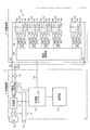
- FIG. 1 is a diagram illustrating a configuration of a charging device 1 according to the present embodiment.
- the charging device 1 includes a storage battery unit 2 that stores electric power, and a charger unit 4 that supplies the electric power to the storage battery unit 2 and charges it.
- the charger unit 4 includes an external power connector 6, a charger 8, a charger controller 10, a current detector 12, a display 14, and a cutoff switch 16.
- the external power connector 6 is a connector to which an external power source 18 such as a commercial power source is connected, and the power of the external power source 18 is input to the charger 8.
- the charger 8 supplies power from the external power source 18 to the storage battery unit 2 and the external load 19 to charge the storage battery unit 2 and drive the external load 19.
- the external load 19 is a target device that supplies power stored in the storage battery unit 2 when the external power source 18 is powered off. More specifically, the battery 8 and the external load 19 are connected in parallel to the charger 8, and the parallel circuit 9 is configured by the battery 2 and the external load 19.
- the charger 8 applies a voltage ⁇ to the parallel circuit 9 to supply a DC charging current Ic to the storage battery unit 2 and supply power to the external load 19.
- the charger 8 When a power failure occurs in the external power supply 18, the charger 8 is in a high impedance state as seen from the parallel circuit 9 including the storage battery unit 2 and the external load 19, so the storage battery unit 2 and the external load 19 are automatically connected in series, Livestock power is supplied from the storage battery unit 2 to the external load 19.
- the charger controller 10 variably controls the current value of the charging current Ic during charging, and is connected to the storage battery unit 2 via the signal line 20.
- the charger controller 10 controls the charging current Ic based on a signal received from the storage battery unit 2 via the signal line 20.
- the current detector 12 is inserted on a series circuit in which the charger 8 and the storage battery unit 2 are connected, the charging current Ic from the storage battery unit 2 to the charger 8, and the discharge current accompanying the discharge from the charger 8. Id is detected and output to the charger controller 10.
- the charger controller 10 variably controls the current value of the charging current Ic based on the detection signal of the current detector 12. In addition, the charger controller 10 captures and samples the detection signal of the current detector 12 at preset time intervals during charging, calculates the charge amount Wc by integrating the sampled charge current Ic, and detects it. Stores the charge amount detection unit 60, the discharge amount detection unit 62 that calculates and detects the discharge amount Wd by integrating the sampled discharge current Id during non-charging, and the number of times of charging counted each time charging is performed. And a storage unit 64. The storage unit 64 further stores in advance a maximum number of times of charging, which is the total number of times that can be charged, which prescribes the life of a battery set 24 to be described later.
- the display 14 displays various information under the control of the charger controller 10, for example, the calculated value of the current storage amount W of the storage battery unit 2, the ratio of the current number of times of charging to the maximum number of times of charging, etc. Is displayed. By displaying this ratio, it is possible to grasp how long the battery set 24 has been used up to the present, and to estimate the replacement time.
- the cut-off switch 16 is a normally closed switch for stopping the discharge of the storage battery unit 2, is inserted on a series circuit connecting the charger 8 and the storage battery unit 2, and is stored under the control of the charger controller 10.
- the storage battery unit 2 is opened to prevent overdischarge. Thereby, the discharge accompanying the electric power supply etc. from the storage battery part 2 to the external load 19 is stopped, and an overdischarge is prevented.
- the cutoff switch 16 is a normally closed switch
- the storage battery unit 2 and the external load 19 are normally held in a conductive state. Since the storage battery unit 2 and the external load 19 are thus kept in a conductive state without being interrupted by a switch or the like in this way, even if a power failure occurs in the external power supply 18, the power supply to the switch is not made. A situation in which the storage battery unit 2 and the external load 19 remain disconnected without stopping and operating is prevented. However, if the storage battery unit 2 and the external load 19 are always kept in a conductive state, the storage power of the storage battery unit 2 is supplied to the external load 19 when the storage battery unit 2 is not charged.
- the charging device 1 performs zero current charging to maintain the charging current Ic flowing into the storage battery unit 2 at substantially zero, whereby electric power is supplied from the storage battery unit 2 to the external load 19 and is discharged wastefully. Is prevented.
- the charger controller 10 sets the parallel circuit 9 so that the charging current Ic flowing into the storage battery unit 2 is maintained at substantially zero based on the detection value of the current detector 12.
- the voltage ⁇ to be applied is feedback controlled. As a result, the differential pressure between the voltage ⁇ and the voltage of the storage battery unit 2 becomes substantially equal, the charging current Ic to the storage battery unit 2 becomes substantially zero, and this state is maintained and the storage from the storage battery unit 2 to the external load 19 is performed.
- the power supply is held in a stopped state.
- the storage battery unit 2 includes a battery set 24 formed by connecting n (n ⁇ 2) secondary batteries (cells) 22 in series, and an overcharge protection circuit (balance circuit) 26.
- the secondary battery 22 is a lithium polymer battery as an example of a lithium ion battery.
- any secondary battery such as a nickel metal hydride battery or a nickel cadmium battery can be used.
- the secondary batteries 22 constituting the battery set 24 are all the same type of secondary batteries.
- the storage battery unit 2 is provided with an anode terminal 30 electrically connected to the anode of the battery set 24 and a cathode terminal 32 electrically connected to the negative electrode of the battery set 24.
- the anode terminal 30 and the cathode A terminal 32 is electrically connected to the charger unit 4.
- the charging current Ic is supplied from the charger unit 4 to the battery set 24 via the anode terminal 30 to charge the battery set 24.
- the overcharge protection circuit 26 protects overcharge to the secondary battery 22 by aligning the voltage balance between the secondary batteries 22, and a discharge route circuit 34 provided in parallel for each secondary battery 22. And a detector group 36 provided for each secondary battery 22 and a battery control unit 38.
- the discharge route circuit 34 is a circuit in which a discharge resistor (balance resistor) 40 and a switching element 42 are connected in series in the route.
- the switching element 42 is a normally open contact, and is closed when the battery voltage Vb of the secondary battery 22 reaches the overcharge protection voltage Vth1.
- This overcharge protection voltage Vth1 is set to a value lower than the full charge voltage Vm according to the type of the secondary battery 22, and is considered to be, for example, full charge when the secondary battery 22 is a lithium polymer battery. It is a value not exceeding 4.2V.
- the discharge route circuit 34 is electrically connected to the secondary battery 22, and the secondary battery 22 starts discharging to the discharge route circuit 34.
- the secondary battery is discharged due to energy discharge due to discharge or a decrease in the amount of inflow into the secondary battery 22 by bypassing the charging current Ic to the discharge route circuit 34.
- the battery voltage Vb of 22 gradually decreases.
- the switching element 42 is opened, and the discharge to the discharge route circuit 34 is stopped. Transition to a charged state.
- the difference between the overcharge protection voltage Vth1 and the protection stop voltage Vth2 is set to such an extent that at least chattering of the switching element 42 can be prevented.
- the charging current Ic flowing into the secondary battery 22 is bypassed by the discharge route circuit 34 and introduced into the secondary battery 22 at the subsequent stage.
- the current value bypassed at this time is determined by the resistance value of the discharge resistor 40.
- the detector group 36 includes an overcharge protection detector 44, an upper limit voltage detector 46, and a discharge cutoff detector 48.
- the overcharge protection detector 44, the upper limit voltage detector 46, and the discharge cutoff detector 48 have a comparator circuit that compares the battery voltage Vb of the secondary battery 22 with a predetermined voltage set for each. Has been.
- the overcharge protection detector 44 detects the battery voltage Vb of the secondary battery 22, compares the battery voltage Vb with the overcharge protection voltage Vth1, and the battery voltage Vb exceeds the overcharge protection voltage Vth1. In this case, the switching element 42 is closed, and the secondary battery 22 is discharged to the discharge route circuit 34.
- the overcharge protection detector 44 opens the switching element 42 and stops discharging the secondary battery 22 to the discharge route circuit 34 when the battery voltage Vb falls below the protection stop voltage Vth2.
- the overcharge protection detector 44 Each time the overcharge protection detector 44 opens or closes the switching element 42, the overcharge protection detector 44 outputs to the battery control unit 38 an open / closed signal indicating the open / closed state of the switching element 42, that is, the start / stop of discharge.
- the battery control unit 38 When such an open / close signal is input, the battery control unit 38 outputs an open / close signal to the charger controller 10 of the charger unit 4 via the signal line 20, whereby the charger controller 10 supplies the discharge route circuit 34. It becomes possible to detect the presence or absence of discharge.
- the charger controller 10 detects that any secondary battery 22 has started discharging to the discharge route circuit 34 based on the open / close signal during charging, the discharge to the discharge route circuit 34 is stopped. Control is performed until the charging current Ic is decreased until such time, and this control will be described later.
- the upper limit voltage detector 46 detects the battery voltage Vb of the secondary battery 22, and when the battery voltage Vb of the secondary battery 22 reaches the upper limit voltage Vth3 that is the upper limit value of the allowed voltage, The data is output to the control unit 38.
- the battery control unit 38 outputs the detection signal to the charger controller 10 via the signal line 20.
- the charger controller 10 detects that the battery voltage Vb of any of the secondary batteries 22 has reached the upper limit of the allowable voltage based on the detection signal from the upper limit voltage detector 46, the storage battery Immediately stop charging the unit 2.
- the discharge cutoff detector 48 detects the battery voltage Vb of the secondary battery 22 while the battery set 24 is not charged, that is, while the power of the battery set 24 is supplied to the external load 19, and this battery
- the voltage Vb is compared with the discharge cutoff voltage Vth4, and when the battery voltage Vb falls below the discharge cutoff voltage Vth4, a detection signal is output to the battery control unit 38.
- the discharge cutoff voltage Vth4 prevents the secondary battery 22 from discharging beyond the end voltage, that is, a so-called overdischarge state, and is set to a voltage that does not fall below the end voltage. For example, when the secondary battery 22 is a lithium polymer battery, the discharge cutoff voltage Vth4 is set to about 3V.
- the charging device 1 includes a temperature detection sensor such as a thermistor for detecting the battery temperature of the battery set 24, and the temperature of the battery set 24 is set to a predetermined temperature (for example, 60 degrees for a lithium polymer battery) during charging. When it exceeds, it is comprised so that charge may be stopped.
- a temperature detection sensor such as a thermistor for detecting the battery temperature of the battery set 24, and the temperature of the battery set 24 is set to a predetermined temperature (for example, 60 degrees for a lithium polymer battery) during charging. When it exceeds, it is comprised so that charge may be stopped.
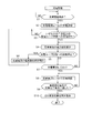
- FIG. 2 is a flowchart illustrating a charging process of the charging device 1
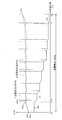
- FIG. 3 is a diagram illustrating a charging pattern by the charging device 1.
- FIG. 3 shows a charging pattern for two secondary batteries 22A and 22B having different battery voltage rise characteristics during charging.
- the charging device 1 monitors the discharge amount Wd by continuously detecting the discharge amount Wd by the discharge amount detection unit 62 at the time of non-charging (step S1), and when the charge start condition is satisfied (step S1).
- Step S2: YES) If the charging start condition is satisfied (Step S1: YES), the charging number I is counted up and updated (Step S3), and then the charging current Ic of the current value Iini is supplied to the storage battery unit 2.
- Charging is started (step S4).
- the charging device 1 monitors the said charge amount Wc by detecting the charge amount Wc continuously by the charge amount detection part 60 at the time of charge (step S5).
- the above charging start conditions include various conditions such as when the battery set 24 is not fully charged, when the cutoff switch 16 is opened to prevent overdischarge, or when a certain period has elapsed since the end of the previous charging. The conditions are set.
- the charging device 1 When the charging device 1 starts supplying the charging current Ic having the current value Iini, the charging device 1 applies to the battery set 24 so that the current value of the charging current Ic becomes the current value Iini while sampling the detection signal from the current detector 12. Adjust the voltage ⁇ . As a result, as shown in FIG. 3, when the supply of the charging current Ic is started and charging is started (time t0), the battery voltages Vb of the secondary batteries 22A and 22B of the battery set 24 become the charging initial voltages V0a and V0b. Starting to rise.
- the secondary battery 22A has a characteristic that the battery voltage Vb is more likely to rise than the secondary battery 22B
- the secondary battery 22B has a secondary voltage before the battery voltage Vb reaches the overcharge protection voltage Vth1.
- Battery voltage Vb of battery 22A reaches overcharge protection voltage Vth1 (time t1).
- the overcharge protection detector 44 of the secondary battery 22A closes the switching element 42 to prevent the secondary battery 22A from being overcharged, and the secondary battery 22A is connected to the discharge route circuit 34 for discharging.
- an open / close signal is output to the charger controller 10, and the discharge to the discharge route circuit 34 of the secondary battery 22A is detected by the charger controller 10. become.
- step S6 when the charger controller 10 detects the discharge of any of the secondary batteries 22 to the discharge route circuit 34 (step S6: YES), the charger controller 10 sequentially decreases the current value of the charging current Ic ( Step S7).
- the current value of the charging current Ic is reduced from the time t1 when the battery voltage Vb of the secondary battery 22A reaches the overcharge protection voltage Vth1.
- the secondary battery 22A gradually lowers the battery voltage Vb and decreases to the protection stop voltage Vth2 as time is discharged to the discharge route circuit 34 and the charging current Ic decreases (time t2), the overcharge protection of the secondary battery 22A occurs.
- the detector 44 opens the switching element 42 and stops discharging the secondary battery 22A to the discharge route circuit 34. This stoppage of discharge to the discharge route circuit 34 is detected by the charger controller 10 by the output of the open / close signal to the charger controller 10.
- step S8 when the charger controller 10 detects the stop of discharge of the secondary battery 22 to the discharge route circuit 34 (step S8: YES), the charger controller 10 stops the decrease in the current value of the charging current Ic. (Step S9), the processing procedure is returned to step S6, and charging is continued. As a result, as shown in FIG. 3, the charging current Ic decreases until the battery voltage Vb of the secondary battery 22A falls to the protection stop voltage Vth2, and is fixed to the current value when the discharge is stopped. When the charging current Ic is decreased, not only the secondary battery 22A but also the battery voltage Vb of the other secondary battery 22B is reduced.
- the charging current Ic is decreased until the discharge of the secondary battery 22 to the discharge route circuit 34 stops. The process is repeated.
- the number of repetitions varies depending on the difference in voltage rise characteristics when the secondary battery 22 is charged, the degree of deterioration, and the like, and is not always repeated a fixed number of times.
- the charging current Ic decreases, and when the charging current Ic is decreased by the processing of step S4, the charging current Ic is reduced. It becomes lower than the charging lower limit current value Ith (time t3).
- This charging lower limit current value Ith is set to a predetermined current value indicated when each secondary battery 22 approaches a fully charged state.
- step S10 when the charger controller 10 detects that the charging current Ic is equal to or lower than the charging lower limit current value Ith (step S10: YES), the charging controller Ic maintains the charging current Ic at the charging lower limit current value Ith. Charging is continued (step S11).
- each secondary battery 22 becomes close to a fully charged state, the battery voltage Vb exceeds the overcharge protection voltage Vth1, and there are a large number of secondary batteries 22 that start discharging to the discharge route circuit 34.
- the charging current Ic is a very small value, the current value bypassed to the discharge route circuit 34 is small and the energy loss in the discharge resistor 40 is small.
- a small amount of the charging current Ic that has not been bypassed into the discharge route circuit 34 flows, and as shown in FIG. The transition is such that Vb exceeds the overcharge protection voltage Vth1 and reaches the full charge voltage Vm (time t4).
- step S12 when the charge amount Wc to the battery set 24 becomes equal to the discharge amount Wd discharged during the non-charge period before the start of charging (step S12: YES), the charging device 1 starts charging (time t0). About 100% of the discharge amount Wd is charged. Therefore, the charging device 1 sets the charging state of the storage battery unit 2 to the zero current charging state, stops charging the storage battery unit 2 (step S13), and ends the charging process.
- the voltage ⁇ of the charger 8 is feedback controlled so that the charging current Ic flowing into the storage battery unit 2 is maintained at substantially zero.
- step S12 the case where the processing of step S12 is performed after the charging current Ic reaches the charging lower limit current value Ith is exemplified.
- the charging device 1 has a charging amount Wc to the battery set 24 during charging. Whether or not the discharge amount Wd becomes equal is continuously monitored, and when the charge amount Wc to the battery set 24 becomes equal to the discharge amount Wd, it is quickly stopped regardless of the current value of the charge current Ic. Also good.
- charging to the battery set 24 is stopped when the charging amount Wc becomes equal to the discharging amount Wd, so that charging without excess or deficiency becomes possible.
- overcharging can be reliably prevented since charging is not performed exceeding the discharge amount Wd.
- the charger controller 10 starts discharging.
- the charging current Ic is decreased until the discharge of the secondary battery 22 to the discharge route circuit 34 is stopped, and charging is continued.
- the fully charged state can be achieved by charging the discharge amount Wd for the charge amount Wc.
- the amount of loss Wd is charged so that the charge amount Wc compensated for the loss is charged.
- the charging may be performed until the charging amount Wc becomes equal to the corrected discharging amount Wd.
- the discharge amount Wd may be corrected in accordance with the reduction of the charging efficiency due to the aging deterioration so that the charging is made up to compensate for the reduction. good.
- the charger controller 10 when the charging current Ic is lower than the predetermined charging lower limit current value Ith, the charger controller 10 maintains the charging current Ic at the charging lower limit current value Ith and supplies it to the battery set 24.
- the charging of the battery set 24 is stopped when the charging amount Wc becomes equal to the discharging amount Wd.
- the battery voltage Vb of many secondary batteries 22 exceeds the overcharge protection voltage Vth1 and is discharged.
- the charging current Ic is a relatively low charge lower limit current value Ith, so that the energy consumed by the discharge root circuit 34 is also suppressed to a small state. Then, each secondary battery 22 can be charged to a fully charged state in a state where the amount of energy consumed in the discharge route circuit 34 is suppressed in this way.
- the charging current Ic is decreased steplessly in accordance with the charging characteristics of each secondary battery 22, so that the charging current is increased in a stepwise manner by a predetermined current value as in the prior art. Since it is difficult to predict the time until the full charge is reached compared to the charge method that decreases the charge, if the charge is completed by counting the time, an accurate full charge state cannot be obtained.
- the charging to the battery set 24 is stopped when the charging amount Wc becomes equal to the discharging amount Wd. Therefore, when the fully charged state is obtained, the charging is quickly performed. Charging can be stopped.
- the charger controller 10 stores the battery set 24 from the battery set 24 to the external device when the battery voltage Vb of any of the secondary batteries 22 decreases to the predetermined discharge cutoff voltage Vth4 during non-charging. Since the power supply is cut off and charging to the battery set 24 is started, overdischarge of each secondary battery 22 can be reliably prevented.
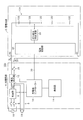
- FIG. 4 is a diagram illustrating a configuration of the charging apparatus 100 according to the present embodiment.
- the charging device 100 of this embodiment includes a gas generation detection circuit 50.
- This gas generation detection circuit 50 detects the generation of gas in any of the secondary batteries 122 during charging and outputs it to the battery control unit 38.
- the battery control unit 38 outputs the signal to the charger controller 10 via the signal line 20.
- the charger controller 10 Each time the generation of gas is detected during charging, the charger controller 10 continues charging by reducing the charging current Ic until the generation of gas stops.
- the charging current Ic is lower than the charging lower limit current value Ith, processing similar to that after step S10 in FIG. 2 described in the first embodiment is performed.
- step S10 when the charger controller 10 detects that the charging current Ic is equal to or lower than the charging lower limit current value Ith (step S10: YES), the charging controller 10 maintains the charging current Ic at the charging lower limit current value Ith and continues charging ( Step S11)
- the amount of charge Wc to the battery set 24 becomes equal to the amount of discharge Wd discharged during non-charging before the start of charging (step S12: YES)
- the state of charge to the battery set 124 is set to zero current. Charging is stopped as the charging state (step S13), and the charging process is terminated.
- the increase in internal resistance of the secondary battery 122 is suppressed, and accordingly, the increase in internal resistance is accompanied. Wasteful consumption of charging power is suppressed, and charging efficiency is increased.
- the gas generation detection circuit 50 is configured to directly detect the presence or absence of gas generation by a gas sensor or the like, or to monitor the battery voltage Vb of each secondary battery 122 to generate a gas from the secondary battery 122. It is good also as a structure which detects generation
- embodiment mentioned above shows the one aspect
- it is configured to suppress excessive consumption of charging power in the overcharge protection circuit 26 during charging, and excessive charging power associated with gas generation in the secondary battery 122 during charging.
- the present invention is not limited to this, and a power consumption factor that consumes charging power other than charging may be generated during charging, and this power consumption factor is solved by reducing the charging current. If so, the present invention can also be applied to charging such a battery set. That is, when consumption of charging power due to a power consumption factor is generated during charging, charging may be continued by reducing the charging current until the consumption stops.
Landscapes
- Engineering & Computer Science (AREA)
- Manufacturing & Machinery (AREA)
- Chemical & Material Sciences (AREA)
- Chemical Kinetics & Catalysis (AREA)
- Electrochemistry (AREA)
- General Chemical & Material Sciences (AREA)
- Power Engineering (AREA)
- Microelectronics & Electronic Packaging (AREA)
- Secondary Cells (AREA)
- Charge And Discharge Circuits For Batteries Or The Like (AREA)
Abstract
Description
この種の充電装置においては、二次電池の電圧が所定電圧に達するまで所定の定電流で充電し、その後、電流値を小さくして充電を行うことで、二次電池の内部抵抗による影響を小さくして、より満充電に近い状態まで充電することを可能にした、いわゆる多段定電流充電方式が提案されている(例えば、特許文献1参照)。
また充電装置は、通常、二次電池の電池電圧が所定電圧に達した場合や、充電電流が所定電流値になった場合、二次電池の電圧が所定電圧に達してから一定時間が経過した場合等に満充電に達したものとみなして充電を停止している。
本発明は、上述した事情に鑑みてなされたものであり、充電時に過不足の無い充電を行い、過充電を確実に防止することができる充電装置及び充電方法を提供することを目的とする。
2 蓄電池部
4 充電器部
8 充電器
10 充電器コントローラー(充電制御手段)
12 電流検出器
14 表示器
22、22A、22B、122 二次電池
24 電池組
26 過充電保護回路
34 放電ルート回路
38 電池制御部
40 放電抵抗
42 スイッチング素子
44 過充電保護用検出器
48 放電遮断用検出器
50 ガス発生検知回路
60 充電量算出部
62 放電量算出部
64 記憶部
Ic 充電電流
Ith 充電下限電流値
Vb 電池電圧
Vth1 過充電保護電圧
Vth2 保護停止電圧
<第1実施形態>
図1は、本実施形態に係る充電装置1の構成を示す図である。この図に示すように、充電装置1は、電力を蓄える蓄電池部2と、この蓄電池部2に電力を供給して充電する充電器部4とを備えている。
充電器部4は、外部電源コネクタ6と、充電器8と、充電器コントローラー10と、電流検出器12と、表示器14と、遮断スイッチ16とを有している。
外部電源コネクタ6は、商用電源等の外部電源18が接続されるコネクタであり、外部電源18の電力が充電器8に入力されている。
さらに詳述すると、充電器8には、蓄電池部2及び外部負荷19が並列に接続されており、これら蓄電池部2及び外部負荷19により並列回路9が構成されている。そして、充電器8は、この並列回路9に電圧αを印加することで、蓄電池部2に直流の充電電流Icを供給し、また、外部負荷19に電力を供給する。
外部電源18に停電が発生すると、蓄電池部2及び外部負荷19から成る並列回路9からみて充電器8がハイインピーダンス状態になるため、蓄電池部2及び外部負荷19が自動的に直列に接続され、蓄電池部2から外部負荷19に畜電力が供給される。
電流検出器12は、充電器8と蓄電池部2とを接続した直列回路上に介挿され、この蓄電池部2から充電器8に向う充電電流Icと、充電器8からの放電に伴う放電電流Idとを検出し、充電器コントローラー10に出力するものである。
また、充電器コントローラー10は、充電時において、予め設定された設定時間ごとに電流検出器12の検出信号を取り込んでサンプリングし、サンプリングした充電電流Icを積算し充電量Wcを算出して検出する充電量検出部60と、非充電時においては、サンプリングした放電電流Idを積算し放電量Wdを算出して検出する放電量検出部62と、充電が行われるごとにカウントした充電回数を記憶する記憶部64とを有している。この記憶部64には、さらに、後述する電池組24の寿命を規定する充電可能な総回数である最大充電回数が予め記憶されている。
また、充電器コントローラー10は、電池組24の交換時期の目安として、最大充電回数に対する現在の充電回数の比率を算出する。
しかし蓄電池部2と外部負荷19との間を常時導通状態で保持すると、蓄電池部2の非充電時には、当該蓄電池部2の蓄電力が外部負荷19に供給されてしまう。そこで、充電装置1は、非充電時には、蓄電池部2に流入する充電電流Icを略ゼロに維持するゼロ電流充電を行うことで、蓄電池部2から外部負荷19に電力が供給され無駄に放電されるのを防止する。
具体的には、非充電時において、充電器コントローラー10は、電流検出器12の検出値に基づいて、蓄電池部2に流入する充電電流Icが略ゼロに維持されるように、並列回路9に印加する電圧αをフィードバック制御する。この結果、電圧αと蓄電池部2の電圧との差圧が略等しくなって蓄電池部2への充電電流Icが略ゼロになり、この状態が保持されて蓄電池部2から外部負荷19への蓄電力の供給が停止状態で保持される。
蓄電池部2は、n個(n≧2)の二次電池(セル)22を直列に接続してなる電池組24と、過充電保護回路(バランス回路)26とを有する。二次電池22は例えばリチウムイオン電池の一例たるリチウムポリマー電池である。この他にも、ニッケル水素電池、ニッケルカドミウム電池等の任意の二次電池を用いることが可能である。ただし、電池組24を構成する二次電池22は全て同一種の二次電池とする。
蓄電池部2には、電池組24の陽極に電気的に接続される陽極端子30、及び電池組24の負極に電気的に接続される陰極端子32が設けられており、これら陽極端子30及び陰極端子32が上記充電器部4に電気的に接続されている。充電時には、充電器部4から陽極端子30を介して電池組24に充電電流Icが供給されて電池組24の充電が行われる。
放電ルート回路34は、経路中に放電抵抗(バランス抵抗)40及びスイッチング素子42を直列に接続した回路である。スイッチング素子42は常開接点であり、二次電池22の電池電圧Vbが過充電保護電圧Vth1に達した場合に閉成する。この過充電保護電圧Vth1は、二次電池22の種類に応じた満充電電圧Vmよりも低い値に設定されたものであり、二次電池22がリチウムポリマー電池の場合は例えば満充電とみなされる4.2Vを超えない値である。
二次電池22の放電中においては、その二次電池22に流入する充電電流Icが放電ルート回路34にバイパスされ、後段の二次電池22に導入される。このときバイパスされる電流値は、放電抵抗40の抵抗値により決定される。
過充電保護用検出器44は、二次電池22の電池電圧Vbを検出し、この電池電圧Vbと上記の過充電保護電圧Vth1とを比較し、電池電圧Vbが過充電保護電圧Vth1を超えた場合に、スイッチング素子42を閉成して、二次電池22を放電ルート回路34へ放電させる。また、過充電保護用検出器44は、電池電圧Vbが保護停止電圧Vth2を下回った場合に、スイッチング素子42を開成して二次電池22の放電ルート回路34への放電を停止する。
充電器コントローラー10は、充電時において、開閉信号に基づいて、いずれかの二次電池22が放電ルート回路34へ放電を開始したことを検知した場合、当該放電ルート回路34への放電が停止されるまで充電電流Icを減少させる制御を行うが、かかる制御については後述する。
なお、この充電装置1は、電池組24の電池温度を検出するサーミスタ等の温度検出センサを有し、充電時に、電池組24の温度が所定温度(例えば、リチウムポリマー電池においては60度)を超えた場合に、充電を停止するように構成されている。
図2は充電装置1の充電処理を示すフローチャートであり、図3は充電装置1による充電パターンを示す図である。なお、図3には、充電時の電池電圧の上昇特性が異なる2つの二次電池22A、22Bについての充電パターンを示している。
上記の充電開始条件には、例えば電池組24が満充電状態でなくなったときや、過放電防止のために遮断スイッチ16が開成したとき、前回の充電終了から一定期間が経過したとき等の各種の条件が設定されている。
この結果、図3に示すように、充電電流Icの供給が開始されて充電が始まると(時間t0)、電池組24の各二次電池22A、22Bの電池電圧Vbが充電初期電圧V0a、V0bから上昇を開始する。
これにより、図3に示すように、二次電池22Aの電池電圧Vbが過充電保護電圧Vth1に達した時間t1から充電電流Icの電流値が減少させられる。
二次電池22Aは、放電ルート回路34への放電、及び、充電電流Icの減少に伴い次第に電池電圧Vbを下げ、保護停止電圧Vth2まで下がると(時間t2)、二次電池22Aの過充電保護用検出器44がスイッチング素子42を開成し、二次電池22Aの放電ルート回路34への放電を停止する。この放電ルート回路34への放電停止は、開閉信号の充電器コントローラー10への出力により、充電器コントローラー10に検知される。
これにより、図3に示すように、二次電池22Aの電池電圧Vbが保護停止電圧Vth2に下がるまで充電電流Icが減少し、放電が停止したときの電流値に固定される。なお、充電電流Icを減少させた場合には、これに伴い、二次電池22Aのみならず他の二次電池22Bの電池電圧Vbも低下する。
そして以降、いずれかの二次電池22の放電ルート回路34への放電が検知されるごとに、その二次電池22の放電ルート回路34への放電が停止するまで充電電流Icを減少する、という処理が繰り返し行われる。この繰り返し回数は、二次電池22の充電時の電圧上昇特性の違いや劣化の度合い等により変動し、常に決まった回数の繰り返しが行われる訳では無い。
充電器コントローラー10は、図2に示すように、充電電流Icが充電下限電流値Ith以下になった事を検出すると(ステップS10:YES)、充電電流Icを充電下限電流値Ithに維持して充電を継続する(ステップS11)。
なお、本実施形態では、ステップS12の処理を充電電流Icが充電下限電流値Ithに至った後に行う場合を例示したが、充電装置1は、充電の間、電池組24への充電量Wcが放電量Wdと等しくなったか否かを継続的に監視し、電池組24への充電量Wcが放電量Wdと等しくなったかときに、充電電流Icの電流値にかかわらず速やかに停止する構成としても良い。
この構成により、充電中においては、各二次電池22の放電ルート回路34への放電が抑制されるため、充電電力が放電によって無駄に消費されることが無く、充電効率が高められる。
これに加え、放電ルート回路34における発熱も小さくなることから、周辺部品の劣化も防止される。
なお、過充電保護回路26での放電等の損失に伴い100%の充電効率が得られない場合には、その損失分を補償した充電量Wcが充電されるように、放電量Wdに損失分を加算する補正を加えた上、この補正後の放電量Wdに充電量Wcが等しくなるまで充電する構成としても良い。さらに、電池組24の劣化に伴い充電効率が低下する場合には、その低下分を補うように充電されるように、経年劣化による充電効率の低下に合わせて放電量Wdを補正する構成としても良い。
この構成により、充電下限電流値Ithに充電電流Icを維持して電池組24への供給を継続することで、多くの二次電池22の電池電圧Vbが過充電保護電圧Vth1を超えて、放電ルート回路34への放電を行う状態になるものの、充電電流Icが比較的小さい充電下限電流値Ithであるため、放電ルート回路34で消費されるエネルギーも小さい状態に抑えられる。そして、このように放電ルート回路34で消費されるエネルギー量が抑えられた状態で、各二次電池22を満充電状態まで充電することができる。
これに対して、本実施形態によれば、充電量Wcが放電量Wdと等しくなったときに電池組24への充電を停止するようにしたため、満充電状態が得られたときに、速やかに充電を停止させることができる。
次いで、本発明の第2実施形態について説明する。
本実施形態では、充電中にガスが発生する性質を有する複数の二次電池122を直列に接続した電池組124に充電を行う充電装置100について説明する。
図4は、本実施形態に係る充電装置100の構成を示す図である。なお、同図において、図1に示したものには同一の符号を付し、その説明を省略する。
この図に示すように、本実施形態の充電装置100は、ガス発生検知回路50を備えている。このガス発生検知回路50は、充電中に、いずれかの二次電池122でのガスの発生を検知して電池制御部38に出力するものである。電池制御部38は、ガスの発生が検知された場合、信号線20を介して充電器コントローラー10に出力する。
なお、充電電流Icが充電下限電流値Ithを下回る場合には、第1実施形態で説明した図2のステップS10以降と同様の処理を行う。すなわち、充電器コントローラー10は、充電電流Icが充電下限電流値Ith以下になった事を検出すると(ステップS10:YES)、充電電流Icを充電下限電流値Ithに維持して充電を継続し(ステップS11)、電池組24への充電量Wcが、充電開始前の非充電時の間に放電された放電量Wdと等しくなった場合(ステップS12:YES)、電池組124への充電状態をゼロ電流充電状態として充電を停止し(ステップS13)、充電処理を終了する。
また、ガス発生検知回路50がガス発生の有無をセンサ等で直接検出する構成である場合には、このガス発生検知回路50の検知結果に基づいて、充電器コントローラー10がガス発生の停止を判断する構成としても良く、また、ガスの発生が停止する所定の電池電圧と二次電池122の電池電圧Vbとを比較することで、間接的にガスの発生停止を検知する構成としても良い。
例えば、上述した実施形態では、充電中における過充電保護回路26での充電電力の余分な消費、及び、充電中における二次電池122でのガス発生に伴う充電電力の余分な消費を抑える構成とした。
しかしながら、これに限らず、電池組が、充電電力を充電以外に無駄に消費する電力消費要因が充電中に発生し得るものであり、なおかつ、この電力消費要因が充電電流を減少させることで解消するものである場合には、そのような電池組への充電にも、本発明を適用することが可能である。
すなわち、充電中に電力消費要因による充電電力の消費が発生された場合には、この消費が停止するまで充電電流を減少させて充電を継続すれば良い。
Claims (5)
- 二次電池に充電電流を供給して充電する充電装置において、
非充電状態の間に前記二次電池から放電された電力量を検出する放電量検出手段と、
充電状態の間に前記二次電池に充電された電力量を検出する充電量検出手段と、
充電時には、前記充電された電力量が前記放電された電力量と等しくなったときに充電を停止する充電制御手段と
を備えることを特徴とする充電装置。 - 複数の二次電池が直列に接続された電池組に充電電流を供給して充電する充電装置において、
前記二次電池ごとに設けられた放電ルート回路を有し、充電中に前記二次電池の電池電圧に基づいて前記放電ルート回路に前記二次電池を接続して放電させ、或いは、前記放電ルート回路から前記二次電池を切断して放電を停止させる過充電保護回路と、
いずれかの前記二次電池が放電ルート回路に放電を開始した場合に、放電を開始した二次電池の放電ルート回路への放電が停止するまで前記充電電流を減少させて充電を継続する充電制御手段と、を備え、
前記充電制御手段は、
前記電池組に充電された電力量が、非充電状態の間に前記電池組から放電された電力量に等しくなったときに充電を停止する
ことを特徴とする充電装置。 - 複数の二次電池が直列に接続された電池組に充電電流を供給して充電する充電装置において、
前記電池組への充電中に、いずれかの前記二次電池からのガスの発生を検知するガス発生検知手段と、
前記ガスの発生が検知されたときに、前記ガスの発生が停止するまで前記充電電流を減少させて充電を継続する充電制御手段と、を備え、
前記充電制御手段は、
前記電池組に充電された電力量が、非充電状態の間に前記電池組から放電された電力量に等しくなったときに充電を停止する
ことを特徴とする充電装置。 - 請求項1乃至3のいずれかに記載の充電装置において、
前記二次電池への充電回数のカウント値と、前記二次電池の寿命を規定する充電可能な総回数とに基づいて、前記二次電池の交換時期の目安を出力する出力手段を備えることを特徴とする充電装置。 - 二次電池に充電電流を供給して充電する充電方法において、
非充電状態の間に前記二次電池から放電された電力量を検出し、
充電時には、前記二次電池に充電された電力量が前記放電された電力量と等しくなったときに充電を停止する
ことを特徴とする充電方法。
Priority Applications (4)
| Application Number | Priority Date | Filing Date | Title |
|---|---|---|---|
| EP09715764.8A EP2249451A4 (en) | 2008-02-25 | 2009-02-16 | CHARGING DEVICE AND CHARGING METHOD |
| CN2009801063984A CN101960689B (zh) | 2008-02-25 | 2009-02-16 | 充电设备和充电方法 |
| KR20107018767A KR101489027B1 (ko) | 2008-02-25 | 2009-02-16 | 충전 장치 및 충전 방법 |
| US12/918,974 US8305038B2 (en) | 2008-02-25 | 2009-02-16 | Charging apparatus and charging method |
Applications Claiming Priority (2)
| Application Number | Priority Date | Filing Date | Title |
|---|---|---|---|
| JP2008-043468 | 2008-02-25 | ||
| JP2008043468A JP4499164B2 (ja) | 2008-02-25 | 2008-02-25 | 充電装置及び充電方法 |
Publications (1)
| Publication Number | Publication Date |
|---|---|
| WO2009107336A1 true WO2009107336A1 (ja) | 2009-09-03 |
Family
ID=41015743
Family Applications (1)
| Application Number | Title | Priority Date | Filing Date |
|---|---|---|---|
| PCT/JP2009/000595 Ceased WO2009107336A1 (ja) | 2008-02-25 | 2009-02-16 | 充電装置及び充電方法 |
Country Status (6)
| Country | Link |
|---|---|
| US (1) | US8305038B2 (ja) |
| EP (1) | EP2249451A4 (ja) |
| JP (1) | JP4499164B2 (ja) |
| KR (1) | KR101489027B1 (ja) |
| CN (1) | CN101960689B (ja) |
| WO (1) | WO2009107336A1 (ja) |
Families Citing this family (21)
| Publication number | Priority date | Publication date | Assignee | Title |
|---|---|---|---|---|
| JP5657257B2 (ja) * | 2009-03-13 | 2015-01-21 | 株式会社東芝 | 充電システム |
| CN102640382A (zh) * | 2010-03-24 | 2012-08-15 | 株式会社杰士汤浅国际 | 二次电池系统 |
| DE102010029427A1 (de) * | 2010-05-28 | 2011-12-01 | Siemens Aktiengesellschaft | Energiespeicheranordnung |
| KR101216898B1 (ko) | 2011-04-22 | 2012-12-28 | 주식회사 현대케피코 | 배터리의 상태 추정 시스템 및 방법 |
| US8816639B2 (en) * | 2011-06-02 | 2014-08-26 | Aerojet Rocketdyne Of De, Inc. | Charge balancing topology |
| US8769327B2 (en) | 2011-10-04 | 2014-07-01 | Advanergy, Inc. | Battery charger management system and method for controlling a charge current by indirectly determining the type and characteristics of a battery via a current consumed by a charger |
| WO2013179599A1 (ja) * | 2012-06-01 | 2013-12-05 | パナソニック株式会社 | 発電システムおよびその制御方法、並びに、蓄電池システムおよびその運用方法 |
| WO2013184695A1 (en) * | 2012-06-04 | 2013-12-12 | Advanergy, Inc. | Battery charger management system and method |
| RU2569676C1 (ru) * | 2012-08-02 | 2015-11-27 | Ниссан Мотор Ко., Лтд. | Система управления зарядом аккумулятора для автоматически управляемого транспортного средства и способ управления зарядом аккумулятора для автоматически управляемого транспортного средства |
| MX338060B (es) * | 2012-08-02 | 2016-04-01 | Nissan Motor | Sistema de administracion de carga de bateria de vehiculo guiado automaticamente y metodo de admisnitracion de carga de bateria. |
| CN104103867B (zh) * | 2013-04-03 | 2016-07-06 | 力博特公司 | 控制智能电池充电的方法、电池控制器及智能电池 |
| CN104252743A (zh) * | 2013-06-26 | 2014-12-31 | 比亚迪股份有限公司 | 充电计费方法及装置 |
| US9403443B2 (en) * | 2014-01-14 | 2016-08-02 | Ford Global Technologies, Llc | Charge balance system and method |
| JP5920639B2 (ja) * | 2014-02-25 | 2016-05-18 | トヨタ自動車株式会社 | 非水電解質二次電池の製造方法 |
| CN103795126B (zh) * | 2014-03-03 | 2016-08-17 | 无锡金雨电子科技有限公司 | 脉冲式充电方法和装置 |
| KR101587713B1 (ko) * | 2014-05-20 | 2016-01-21 | 에너지 컨트롤 리미티드 | 과충전 방지 장치를 가지는 2차 배터리 |
| TWI661650B (zh) * | 2018-03-23 | 2019-06-01 | 加百裕工業股份有限公司 | 並聯電池系統及方法 |
| CN112018831B (zh) * | 2019-05-28 | 2023-06-16 | 荣耀终端有限公司 | 一种充电控制方法、充电控制装置及电子设备 |
| CN110350632B (zh) * | 2019-08-20 | 2024-09-03 | 深圳市道通智能航空技术股份有限公司 | 一种电池均衡自放电电路和无人机 |
| CN111129630B (zh) * | 2019-12-30 | 2021-07-06 | 深圳市科陆电子科技股份有限公司 | 储能系统的能效优化方法 |
| CN116190829A (zh) * | 2023-02-22 | 2023-05-30 | 深圳市拓邦锂电池有限公司 | 电池预处理方法、装置、计算机设备和存储介质 |
Citations (6)
| Publication number | Priority date | Publication date | Assignee | Title |
|---|---|---|---|---|
| JPH0233556U (ja) * | 1988-08-23 | 1990-03-02 | ||
| JPH05172914A (ja) * | 1991-12-24 | 1993-07-13 | Matsushita Electric Works Ltd | 電池の寿命報知装置 |
| JPH0779504A (ja) * | 1993-09-07 | 1995-03-20 | Kubota Corp | 小型電動車 |
| JPH07264780A (ja) * | 1994-03-18 | 1995-10-13 | Nissan Motor Co Ltd | 組電池の充放電制御装置 |
| JPH11329510A (ja) * | 1998-05-11 | 1999-11-30 | Matsushita Electric Ind Co Ltd | 電池の充電方法 |
| JP2003087991A (ja) | 2001-09-07 | 2003-03-20 | Nissan Motor Co Ltd | 充電装置および充電方法 |
Family Cites Families (24)
| Publication number | Priority date | Publication date | Assignee | Title |
|---|---|---|---|---|
| US4371825A (en) * | 1981-06-04 | 1983-02-01 | Energy Development Associates, Inc. | Method of minimizing the effects of parasitic currents |
| JPH086958B2 (ja) | 1988-07-25 | 1996-01-29 | 三洋電機株式会社 | 遠隔制御装置 |
| US5475294A (en) * | 1991-12-27 | 1995-12-12 | Nippon Densan Corporation | Charge controller for battery charger |
| US5900720A (en) * | 1993-09-10 | 1999-05-04 | Kallman; William R. | Micro-electronic power supply for electrochromic eyewear |
| JPH07336905A (ja) * | 1994-06-08 | 1995-12-22 | Nissan Motor Co Ltd | 組電池の充電装置 |
| FR2725849B1 (fr) * | 1994-10-18 | 1996-12-20 | Accumulateurs Fixes | Procede de regulation de la charge d'un ensemble accumulateur electrique et agencement mettant en oeuvre ce procede |
| US6104165A (en) * | 1995-06-16 | 2000-08-15 | Zip Charge Corporation | Multi-stage battery charging system |
| JP3496360B2 (ja) * | 1995-09-14 | 2004-02-09 | 日産自動車株式会社 | 組電池の充電制御装置 |
| JP3503295B2 (ja) * | 1995-09-18 | 2004-03-02 | 日産自動車株式会社 | 組電池の充電制御方法および装置 |
| JPH09308126A (ja) * | 1996-05-17 | 1997-11-28 | Nissan Motor Co Ltd | 充電装置 |
| US6040685A (en) * | 1996-08-16 | 2000-03-21 | Total Battery Management, Inc. | Energy transfer and equalization in rechargeable lithium batteries |
| JP3767767B2 (ja) * | 1997-11-28 | 2006-04-19 | ソニー株式会社 | 充電制御方法及び充電制御装置 |
| US6642693B2 (en) * | 2000-11-21 | 2003-11-04 | Nagano Japan Radio Co., Ltd. | Voltage equalizing apparatus for battery devices |
| JP3767422B2 (ja) * | 2001-06-01 | 2006-04-19 | 日産自動車株式会社 | 充電方法および充電装置 |
| US7378818B2 (en) * | 2002-11-25 | 2008-05-27 | Tiax Llc | Bidirectional power converter for balancing state of charge among series connected electrical energy storage units |
| US7986124B2 (en) * | 2003-09-22 | 2011-07-26 | Valence Technology, Inc. | Electrical systems, battery assemblies, and battery assembly operational methods |
| JP3832660B2 (ja) * | 2003-10-29 | 2006-10-11 | 株式会社Nttファシリティーズ | 充電装置 |
| US20060022646A1 (en) * | 2004-07-28 | 2006-02-02 | Moore Stephen W | Method for battery cold-temperature warm-up mechanism using cell equilization hardware |
| US7525285B2 (en) * | 2004-11-11 | 2009-04-28 | Lg Chem, Ltd. | Method and system for cell equalization using state of charge |
| JP4186916B2 (ja) * | 2004-11-18 | 2008-11-26 | 株式会社デンソー | 組電池管理装置 |
| JP4628284B2 (ja) * | 2006-03-01 | 2011-02-09 | エナックス株式会社 | 二次電池の充電方法及び装置 |
| JP2008010295A (ja) * | 2006-06-29 | 2008-01-17 | Hokuriku Electric Power Co Inc:The | 二次電池の保温方法及び保温装置 |
| CN101325272B (zh) * | 2007-06-11 | 2010-06-02 | 吴文恺 | 平衡充电方法及其装置 |
| US7830120B2 (en) * | 2007-09-18 | 2010-11-09 | Nexergy, Inc. | Low side N-channel FET protection circuit |
-
2008
- 2008-02-25 JP JP2008043468A patent/JP4499164B2/ja active Active
-
2009
- 2009-02-16 KR KR20107018767A patent/KR101489027B1/ko not_active Expired - Fee Related
- 2009-02-16 WO PCT/JP2009/000595 patent/WO2009107336A1/ja not_active Ceased
- 2009-02-16 CN CN2009801063984A patent/CN101960689B/zh not_active Expired - Fee Related
- 2009-02-16 US US12/918,974 patent/US8305038B2/en not_active Expired - Fee Related
- 2009-02-16 EP EP09715764.8A patent/EP2249451A4/en not_active Withdrawn
Patent Citations (6)
| Publication number | Priority date | Publication date | Assignee | Title |
|---|---|---|---|---|
| JPH0233556U (ja) * | 1988-08-23 | 1990-03-02 | ||
| JPH05172914A (ja) * | 1991-12-24 | 1993-07-13 | Matsushita Electric Works Ltd | 電池の寿命報知装置 |
| JPH0779504A (ja) * | 1993-09-07 | 1995-03-20 | Kubota Corp | 小型電動車 |
| JPH07264780A (ja) * | 1994-03-18 | 1995-10-13 | Nissan Motor Co Ltd | 組電池の充放電制御装置 |
| JPH11329510A (ja) * | 1998-05-11 | 1999-11-30 | Matsushita Electric Ind Co Ltd | 電池の充電方法 |
| JP2003087991A (ja) | 2001-09-07 | 2003-03-20 | Nissan Motor Co Ltd | 充電装置および充電方法 |
Non-Patent Citations (1)
| Title |
|---|
| See also references of EP2249451A4 |
Also Published As
| Publication number | Publication date |
|---|---|
| US8305038B2 (en) | 2012-11-06 |
| EP2249451A4 (en) | 2016-04-06 |
| US20110169453A1 (en) | 2011-07-14 |
| KR101489027B1 (ko) | 2015-02-02 |
| CN101960689A (zh) | 2011-01-26 |
| EP2249451A1 (en) | 2010-11-10 |
| JP4499164B2 (ja) | 2010-07-07 |
| JP2009201337A (ja) | 2009-09-03 |
| KR20100114097A (ko) | 2010-10-22 |
| CN101960689B (zh) | 2013-10-30 |
Similar Documents
| Publication | Publication Date | Title |
|---|---|---|
| JP4499164B2 (ja) | 充電装置及び充電方法 | |
| JP4865103B2 (ja) | 充電装置及び充電方法 | |
| JP5618986B2 (ja) | 充電装置 | |
| KR100885291B1 (ko) | 충전 장치 | |
| US7598706B2 (en) | Cell balancing battery pack and method of balancing the cells of a battery | |
| JP2015073429A (ja) | 直列群のバッテリまたはキャパシタのセル充電状態および放電状態の分岐を検出する方法 | |
| CN101192757A (zh) | 充电系统、充电装置以及电池组件 | |
| CN101013764A (zh) | 用于无绳电动工具系统的电池组的充电方法 | |
| JP2008005693A (ja) | 電池装置 | |
| JP5474438B2 (ja) | 二次電池装置 | |
| JP2020031470A (ja) | 二次電池の充電制御方法及び充電制御システム | |
| JP2011182479A (ja) | リチウムイオン組電池の充電システムおよび充電方法 | |
| JPH0935757A (ja) | 独立型太陽光発電システムの収支判定制御方式および独立型太陽光発電システムの電池寿命判定方法 | |
| CN103580071A (zh) | 具有电池管理系统的充电装置 | |
| JPH07335266A (ja) | 組電池及びその充電装置 | |
| KR20220111119A (ko) | 배터리 손상 방지를 위한 급속충전 장치 및 방법 |
Legal Events
| Date | Code | Title | Description |
|---|---|---|---|
| WWE | Wipo information: entry into national phase |
Ref document number: 200980106398.4 Country of ref document: CN |
|
| 121 | Ep: the epo has been informed by wipo that ep was designated in this application |
Ref document number: 09715764 Country of ref document: EP Kind code of ref document: A1 |
|
| REEP | Request for entry into the european phase |
Ref document number: 2009715764 Country of ref document: EP |
|
| WWE | Wipo information: entry into national phase |
Ref document number: 12918974 Country of ref document: US Ref document number: 2009715764 Country of ref document: EP |
|
| ENP | Entry into the national phase |
Ref document number: 20107018767 Country of ref document: KR Kind code of ref document: A |
|
| NENP | Non-entry into the national phase |
Ref country code: DE |