WO2009107344A1 - Corps de contact mobile et commutateur associé - Google Patents
Corps de contact mobile et commutateur associé Download PDFInfo
- Publication number
- WO2009107344A1 WO2009107344A1 PCT/JP2009/000722 JP2009000722W WO2009107344A1 WO 2009107344 A1 WO2009107344 A1 WO 2009107344A1 JP 2009000722 W JP2009000722 W JP 2009000722W WO 2009107344 A1 WO2009107344 A1 WO 2009107344A1
- Authority
- WO
- WIPO (PCT)
- Prior art keywords
- light
- movable contact
- light emitting
- light guide
- contact body
- Prior art date
- Legal status (The legal status is an assumption and is not a legal conclusion. Google has not performed a legal analysis and makes no representation as to the accuracy of the status listed.)
- Ceased
Links
Images



Classifications
-
- H—ELECTRICITY
- H01—ELECTRIC ELEMENTS
- H01H—ELECTRIC SWITCHES; RELAYS; SELECTORS; EMERGENCY PROTECTIVE DEVICES
- H01H13/00—Switches having rectilinearly-movable operating part or parts adapted for pushing or pulling in one direction only, e.g. push-button switch
- H01H13/70—Switches having rectilinearly-movable operating part or parts adapted for pushing or pulling in one direction only, e.g. push-button switch having a plurality of operating members associated with different sets of contacts, e.g. keyboard
- H01H13/83—Switches having rectilinearly-movable operating part or parts adapted for pushing or pulling in one direction only, e.g. push-button switch having a plurality of operating members associated with different sets of contacts, e.g. keyboard characterised by legends, e.g. Braille, liquid crystal displays, light emitting or optical elements
-
- H—ELECTRICITY
- H01—ELECTRIC ELEMENTS
- H01H—ELECTRIC SWITCHES; RELAYS; SELECTORS; EMERGENCY PROTECTIVE DEVICES
- H01H2205/00—Movable contacts
- H01H2205/016—Separate bridge contact
-
- H—ELECTRICITY
- H01—ELECTRIC ELEMENTS
- H01H—ELECTRIC SWITCHES; RELAYS; SELECTORS; EMERGENCY PROTECTIVE DEVICES
- H01H2215/00—Tactile feedback
- H01H2215/034—Separate snap action
- H01H2215/036—Metallic disc
-
- H—ELECTRICITY
- H01—ELECTRIC ELEMENTS
- H01H—ELECTRIC SWITCHES; RELAYS; SELECTORS; EMERGENCY PROTECTIVE DEVICES
- H01H2219/00—Legends
- H01H2219/036—Light emitting elements
- H01H2219/044—Edge lighting of layer
-
- H—ELECTRICITY
- H01—ELECTRIC ELEMENTS
- H01H—ELECTRIC SWITCHES; RELAYS; SELECTORS; EMERGENCY PROTECTIVE DEVICES
- H01H2219/00—Legends
- H01H2219/054—Optical elements
- H01H2219/062—Light conductor
Definitions
- the present invention relates to a movable contact body used for operation of various electronic devices and a switch using the same.
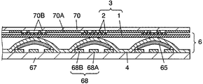
- FIG. 9 is a sectional view of a conventional switch
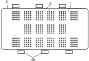
- FIG. 10 is a plan view thereof.
- This switch has a movable contact body 6, a wiring board 67, a plurality of light emitting elements 69, and a display sheet 70.
- the movable contact body 6 has a light guide sheet 3, a cover sheet 4, and a plurality of movable contacts 65.
- the light guide sheet 3 includes a base material 1 and a light emitting unit 2.
- the film-like substrate 1 is light transmissive.
- the uneven light-emitting portion 2 is provided at a predetermined location on the upper surface of the substrate 1.
- the cover sheet 4 has a film shape, and the movable contact 65 made of a thin metal plate has a dome shape.
- the cover sheet 4 is affixed to the lower surface of the light guide sheet 3 with an adhesive (not shown) at a predetermined location on the outer periphery.
- the movable contact 65 is attached to the lower surface of the cover sheet 4 below the light emitting unit 2.
- a plurality of wiring patterns are formed on the upper and lower surfaces of the wiring board 67.
- a plurality of fixed contacts 68 are provided on the upper surface of the wiring board 67.
- Each of the fixed contacts 68 is formed of a substantially circular center fixed contact 68A and a substantially horseshoe-shaped or substantially ring-shaped outer fixed contact 68B surrounding the center fixed contact 68A.
- the movable contact body 6 is mounted on the wiring board 67 such that the outer periphery of each movable contact 65 is placed on the outer fixed contact 68B, and the center of the lower surface of the movable contact 65 is opposed to the central fixed contact 68A with a predetermined gap. It is affixed on the top surface.
- the light emitting element 69 is composed of a light emitting diode or the like.
- the plurality of light emitting elements 69 are mounted on the upper surface of the wiring board 67 on the side of the light guide sheet 3, and are disposed with the light emitting surface facing the end surface of the base material 1.
- the film-like display sheet 70 is light transmissive. On the lower surface of the display sheet 70, a light shielding portion 70A and a plurality of display portions 70B are formed.
- the light shielding part 70A is formed by printing or the like.
- Each of the display portions 70B is formed by cutting out predetermined portions of the light shielding portion 70A into shapes such as characters and symbols.
- Each display unit 70 ⁇ / b> B is disposed above the light emitting unit 2.
- the switch thus configured is arranged on the operation surface of the electronic device, and a plurality of central fixed contacts 68A, outer fixed contacts 68B, and light emitting elements 69 are connected to the electronic circuit of the device (not shown) via a wiring pattern or the like. Connected).
- the movable contact 65 When the user presses the display sheet 70 downward at a position corresponding to one of the display units 70B, the light guide sheet 3 and the cover sheet 4 are bent and the dome-shaped central portion of the movable contact 65 is pressed.
- the movable contact 65 When a predetermined pressing force is applied, the movable contact 65 is elastically reversed downward with a click feeling, and the center of the lower surface of the movable contact 65 contacts the central fixed contact 68A.
- the center fixed contact 68 ⁇ / b> A and the outer fixed contact 68 ⁇ / b> B are electrically connected via the movable contact 65.
- the movable contact 65 is elastically reversed upward by the elastic restoring force.
- the center of the lower surface of the movable contact 65 is separated from the center fixed contact 68A, and the center fixed contact 68A and the outer fixed contact 68B are electrically disconnected.
- each function of the device is switched.
- the light emitting element 69 when power is supplied to the light emitting element 69 from the electronic circuit of the device, the light emitting element 69 emits light, and this light enters the light guide sheet 3 from the end face and reflects inward while reflecting inside the base material 1. move on. Further, this light is diffused and reflected by the light emitting unit 2, and illuminates the display unit 70B from below. Therefore, even when the surrounding is dark, the user can identify the display of characters and symbols on the display unit 70B, and can easily operate the device.
- This type of movable contact body is disclosed in Patent Document 1, for example.
- the present invention is a movable contact body capable of various illuminations with a simple configuration and a switch using the movable contact body.
- the movable contact body of the present invention includes a light guide sheet, a cover sheet, a movable contact, and a light transmissive light guide.
- the light guide sheet includes a film-like base material and a light emitting portion provided on the base material in a concavo-convex shape.
- the cover sheet is provided to face the base material.
- the movable contact made of a thin metal plate is attached to the cover sheet at a position corresponding to the light emitting unit, and has a dome shape and elasticity.
- the light guide part is provided in the cover sheet at a position excluding the place where the movable contact is provided, or at a position excluding the place where the light emitting part of the light guide sheet is provided.
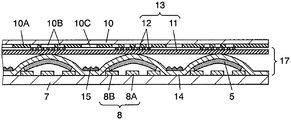
- FIG. 1 is a cross-sectional view of a movable contact body according to Embodiment 1 of the present invention.
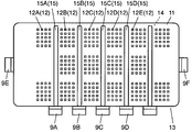
- FIG. 2 is a plan view of the movable contact body shown in FIG.
- FIG. 3 is a sectional view of a switch using the movable contact body shown in FIG.
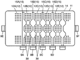
- FIG. 4 is a plan view of a movable contact body having a light guide unit of another configuration according to the first embodiment of the present invention.
- FIG. 5 is a plan view of a movable contact body having a light guide portion of still another configuration according to Embodiment 1 of the present invention.
- FIG. 6 is a plan view of a movable contact body having a light guide portion of still another configuration according to Embodiment 1 of the present invention.
- FIG. 1 is a cross-sectional view of a movable contact body according to Embodiment 1 of the present invention.
- FIG. 2 is a plan view of the movable contact body shown in FIG.
- FIG. 3
- FIG. 7 is a plan view of a movable contact body having a light guide portion of still another configuration according to Embodiment 1 of the present invention.
- FIG. 8 is a cross-sectional view of a switch according to Embodiment 2 of the present invention.
- FIG. 9 is a sectional view of a conventional switch.
- FIG. 10 is a plan view of the switch shown in FIG.
- (Embodiment 1) 1 is a sectional view of a movable contact body according to Embodiment 1 of the present invention
- FIG. 2 is a plan view of the same.
- the movable contact body 17 includes a light guide sheet 13, a cover sheet 14, a plurality of movable contacts 5, and a plurality of light guide portions 15 (15A, 15B, 15C, 15D, etc.).
- the light guide sheet 13 includes a base material 11 and a plurality of light emitting units 12.
- the film-like base material 11 is light transmissive and is formed of a flexible resin such as polyethylene terephthalate, polycarbonate, polyurethane, or silicone.
- the uneven light emitting portion 12 is provided at a predetermined location on the upper surface of the substrate 11.
- the light emitting part 12 can be formed, for example, by collecting and printing dot parts made of a material such as translucent polyester or epoxy. Or the uneven
- the light emitting unit 12 may be formed on the lower surface of the base material 11.
- the cover sheet 14 is a film.
- the movable contact 5 is made of a thin metal plate such as copper alloy or steel, has a dome shape, and has elasticity.
- the cover sheet 14 is attached to the lower surface of the light guide sheet 13 with an adhesive (not shown) at a predetermined location on the outer periphery thereof. That is, the cover sheet 14 is provided to face the base material 11.
- a plurality of movable contacts 5 are affixed to the lower surface of the cover sheet 14 at positions corresponding to the plurality of light emitting portions 12 respectively. That is, the movable contact 5 is mounted on the surface of the cover sheet 14 opposite to the surface facing the light guide sheet 13.
- a plurality of light transmissive light guides 15 are arranged on the upper surface of the cover sheet 14 between the movable contacts 5. That is, the light guide 15 is provided at a position on the cover sheet 14 excluding the location where the movable contact 5 is provided.
- the light guide 15 is made of a light-transmitting sheet material such as polyethylene terephthalate, polycarbonate, polyurethane, silicone, etc., like the substrate 11. Such a sheet material is processed and formed into a substantially belt-like shape, and the light guide portion 15 is formed with the upper or lower surface thereof being uneven.
- the light guide unit 15 is disposed on the upper surface of the cover sheet 14 with an adhesive interposed therebetween.
- the light guide portion 15 including the adhesive is illustrated as an integral part in which the upper surface side is formed in an uneven shape.
- a dot portion made of a material such as translucent polyester or epoxy is printed and formed in the same manner as the light emitting portion 12 of the light guide sheet 13. That's fine.
- the light guide part 15A is arranged corresponding to the lower position between the light emitting part 12A and the light emitting part 12B.
- the light guide unit 15B is disposed corresponding to the lower position between the light emitting unit 12B and the light emitting unit 12C.
- the light guide unit 15C is disposed corresponding to a lower position between the light emitting unit 12C and the light emitting unit 12D.
- the light guide unit 15D is disposed corresponding to the lower position between the light emitting unit 12D and the light emitting unit 12E.
- the plurality of light guides 15 are provided at positions excluding the locations where the plurality of movable contacts 5 are disposed, that is, positions between the movable contacts 5. That is, the light guide 15 does not overlap above the movable contact 5, and the overall thickness does not increase. Therefore, compared with a configuration in which a plurality of light guide sheets and light guide portions are stacked above the movable contact 5 to illuminate various lights, the overall thickness does not increase and the thickness does not increase. Illumination becomes possible.
- the lower surface of the cover sheet 14 is covered with a film-like separator 16.
- the separator 16 is made of polyethylene terephthalate or the like. Since the separator 16 is attached so as to cover the entire lower surface of the cover sheet 14, dust or the like does not adhere to the lower surface of the movable contact 5 during storage or transportation.
- FIG. 3 is a sectional view of a switch using the movable contact body 17.
- This switch includes a movable contact body 17, a wiring board 7, a plurality of light emitting elements 9A to 9F, and a display sheet 10.
- the wiring board 7 is composed of a film such as polyethylene terephthalate or polycarbonate, or a sheet of paper phenol or epoxy containing glass.
- a plurality of wiring patterns (not shown) are formed on the upper and lower surfaces of the wiring substrate 7 using copper or the like.
- a plurality of fixed contacts 8 are provided on the upper surface of the wiring board 7 by a conductive material such as carbon.
- Each fixed contact 8 includes a substantially circular central fixed contact 8A and a substantially horseshoe-shaped or substantially ring-shaped outer fixed contact 8B surrounding the fixed fixed contact 8A.
- a movable contact body 17 from which the separator 16 has been peeled off is affixed to the upper surface of the wiring board 7.
- the outer periphery of each movable contact 5 is placed on the corresponding outer fixed contact 8B, and the center of the lower surface of the movable contact 5 is arranged to face the central fixed contact 8A with a predetermined gap. .
- the light emitting elements 9A to 9F are composed of light emitting diodes or the like.
- the light emitting elements 9A to 9F are mounted on the upper surface of the wiring board 7 on the side of the light guide sheet 13. Specifically, as shown in FIG. 2, the light emitting element 9 ⁇ / b> A is disposed with the light emitting surface facing the end surface of the light guide portion 15 ⁇ / b> A on the cover sheet 14.
- the light emitting element 9B is disposed with the light emitting surface facing the end surface of the light guide portion 15B.
- the light emitting element 9C is arranged with the light emitting surface facing the end surface of the light guide portion 15C.
- the light emitting element 9D is disposed with the light emitting surface facing the end surface of the light guide portion 15D.
- the light emitting elements 9E and 9F are arranged with the light emitting surface facing the end surface of the substrate 11.
- the light emitting elements 9A to 9D are first light emitting elements provided at positions where light can be projected to the end portions of the light guide portions 15A to 15D, respectively, and the light emitting elements 9E and 9F can project light to the end portions of the substrate 11. It is the 2nd light emitting element provided in the position.
- the film-like display sheet 10 is light transmissive. On the lower surface of the display sheet 10, a light shielding portion 10A, a plurality of display portions 10B, and a plurality of light transmitting portions 10C are formed.
- the light shielding part 10A is formed by printing or the like.
- Each display unit 10B is formed by cutting out a predetermined portion of the light shielding unit 10A into a shape such as a character or a symbol.
- Each display unit 10 ⁇ / b> B is disposed above the light emitting unit 12.
- Each translucent part 10C is formed by cutting out a predetermined portion of the light shielding part 10A between the display parts 10B.
- the translucent portion 10C is formed in a substantially band shape, for example. In this way, the switch is configured.
- the structure of the display sheet 10 is not specifically limited to what was mentioned above.
- the display sheet 10 may be made of a non-translucent resin, a part thereof may be hollowed out, and a transparent resin may be embedded in the hollowed part to form a portion corresponding to the translucent part 10C.
- the switch configured as described above is arranged on the operation surface of the electronic device, and the central fixed contact 8A, the outer fixed contact 8B, and the light emitting elements 9A to 9F are connected to the electronic circuit ( (Not shown).
- the light guide sheet 13 and the cover sheet 14 are bent and the dome-shaped central portion of the movable contact 5 is pressed.
- the movable contact 5 is elastically reversed downward with a click feeling, and the center of the lower surface of the movable contact 5 contacts the central fixed contact 8A.
- the central fixed contact 8 ⁇ / b> A and the outer fixed contact 8 ⁇ / b> B are electrically connected via the movable contact 5.
- a columnar portion (not shown) may be further provided so as to be sandwiched between the light guide sheet 13 and the cover sheet 14 in correspondence with the position of the central portion of the movable contact 5.
- the movable contact 5 When the user releases the pressing force on the display sheet 10, the movable contact 5 is elastically reversed upward by the elastic return force, and the center of the lower surface of the movable contact 5 is separated from the central fixed contact 8A. Therefore, the center fixed contact 8A and the outer fixed contact 8B are electrically disconnected. Depending on the electrical contact / separation of the fixed contact 8, each function of the device is switched.
- the light emitting elements 9A to 9F When power is supplied to the light emitting elements 9E and 9F and they emit light, the light enters the light guide sheet 13 from the end face of the base material 11 and reflects the inside of the base material 11 while reflecting the inside. Proceed to Further, this light is diffused and reflected by the light emitting unit 12 (12A, 12B, etc.) on the upper surface of the base material 11, and the display unit 10B of the upper display sheet 10 is illuminated from below, and the plurality of display units 10B are illuminated. It is. Therefore, even when the surrounding is dark, the user can identify the display of characters and symbols on the display unit 10B, and can easily operate the device.
- the light emitting element 9A emits light
- this light enters from the end face of the light guide portion 15A on the cover sheet 14, and proceeds inward while reflecting the light guide portion 15A. Then, the light is diffused and reflected on the upper surface of the light guide portion 15A, and the entire light guide portion 15A emits light. This light passes through the substrate 11, and the upper light transmitting portion 10C is illuminated from below.
- the light emitting element 9B when the light emitting element 9B emits light, this light enters from the end face of the light guide 15B and the entire light guide 15B emits light.
- the entire light guide unit 15C emits light
- the light emitting element 9D when the light emitting element 9D emits light, the entire light guide unit 15D emits light.
- the light emitting element 9E and the light emitting element 9F may have white light emission, the light emitting element 9A light blue, the light emitting element 9B orange, and the light emitting element 9C green.
- the light emitting unit 12 emits white light
- the light guide unit 15A emits blue light
- the light guide unit 15B emits orange light
- the light guide unit 15C emits green light. Therefore, the display unit 10B is illuminated in a different color such that the display unit 10B is white, and the translucent unit 10C between them is blue, orange, and green.
- the light emitting elements 9A, 9B, and 9C are made to have the same emission color, and power is supplied with a certain time difference from the electronic circuit of the device to the light emitting elements 9A to 9F.
- the light guide 15A between the light emitting part 12A and the light emitting part 12B emits light
- the light guide part 15B between the light emitting part 12B and the light emitting part 12C emits light
- the light guide unit 15C between the light emitting unit 12C and the light emitting unit 12D emits light.
- the light guides 15A to 15C emit light in order, and the light transmitting parts 10C between the display parts 10B are sequentially illuminated for each column.
- the switch according to the present embodiment when the user presses the display sheet 10, the upper surface of the light guide sheet 13 is pressed, the movable contact 5 is elastically inverted, and the fixed contact 8 is electrically turned on. Become.
- the light from the light emitting elements 9A to 9D is introduced into the light guide portions 15A to 15D on the light guide sheet 13 and the cover sheet 14 from the end surfaces.
- the plurality of light emitting units 12 and the light guide units 15A to 15D arranged at lower positions therebetween emit light. Therefore, the plurality of display portions 10B of the display sheet 10 and the plurality of light transmitting portions 10C therebetween are illuminated.
- the translucent unit 10C between them can be illuminated with different colors, or the translucent unit 10C can be illuminated sequentially with a time difference. That is, various illuminations of the plurality of display units 10B and the translucent unit 10C are possible with a simple configuration.
- positioning location of the movable contact 5 was demonstrated.
- a plurality of light guide portions 15 may be provided on the lower surface of the cover sheet 14.
- One light guide 15 may be provided.
- FIGS. 4 to 7 are plan views of a movable contact body having a light guide portion of another configuration in the present embodiment.
- a connecting portion 20 ⁇ / b> A (20) that partially connects the light guide portion 15 ⁇ / b> A and the light guide portion 15 ⁇ / b> B at a position excluding the location where the movable contact 5 is disposed is provided.
- a connecting portion 20B (20) for connecting the light guide portion 15C and the light guide portion 15D is provided.
- the connecting portion 20A is also integrally formed of the same material as the light guide portions 15A and 15B, the connecting portion 20A is also light transmissive. And light guide part 15A and 15B containing 20 A of connection parts will be in the same light emission state.
- the light emitting elements 9A and 9B are turned on simultaneously with the same emission color.
- the light emitting elements 9A and 9B may emit light in different colors.
- the light guide portions 15C and 15D, the connecting portion 20B, and the light emitting elements 9C and 9D are same applies.
- the pair of light guide portions 15 may be connected by a plurality of connecting portions 20. Then, the light guides 15C and 15D may emit light with different colors and timings with respect to the light guides 15A and 15B.
- the outer shape of the movable contact 5 is circular or oval when viewed from above.
- the movable contacts 5 having such a shape are arranged in a matrix.
- the light emitting units 12A to 12E are arranged corresponding to the position of the movable contact 5. For this reason, in the light emitting units 12A to 12E, the distance between the diagonally adjacent portions may be increased. Therefore, for example, as shown in FIG. 5, in the plurality of strip-shaped light guide portions 15A, 15B, 15C, 15D, etc., it is preferable to integrally form the protruding portions 30 that fill the spaces between the light emitting portions adjacent to each other.
- the thickness of the light guide 15 With such a shape, a wide range including a spatial position formed in an obliquely adjacent portion is favorably emitted by the light guide unit.
- the position where the thickness is changed is not limited to the above position, and the position and the shape of the convex portion 30 may be appropriately set as necessary. Thus, by setting it as the light guide part 15 with the convex part 30, the part in which the light emission part 12 is not provided can also be illuminated.
- the light guide unit 40 provided on the cover sheet 14 surrounds the periphery of the light emitting unit 12 arranged according to the position of the movable contact 5. Further, as shown in FIG. 6, a configuration in which three rows (in the vertical direction in the drawing) including the light emitting units 12 are integrally connected may be used.
- the light guide section 40 has a shape in which the connection sections 20 are arranged and connected to all positions except for the places where the movable contacts 5 of the strip-shaped light guide sections 15A and 15B shown in FIG.
- the light emitting elements 9A and 9B may be arranged so that light enters from the end portions corresponding to the strip portions 40A and 40B.
- the light guide element 45 is arranged so that the light of the light emitter 9G is incident from the corner portion constituting the L shape by arranging a light guide portion 45 having a straight L shape at the outer peripheral position of the cover sheet 14. May be. That is, the light guide unit 45 is provided at the outer peripheral position of the movable contact body. If the light guide unit 45 emits light, the cover sheet 14 is well illuminated to the position of the outer peripheral end.
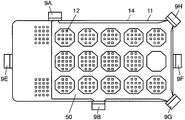
- a mesh-shaped light guide unit 50 is provided so as to individually surround each of the light emitting units 12 arranged in a matrix.
- This configuration is a derivative of the configuration shown in FIG.
- the arrangement of the light emitting elements 9A, 9B, 9G, and 9H is preferably an arrangement in which the entire light emitting state is uniform, but is not particularly limited.
- the light guide section can be arranged at any position except the place where the movable contact 5 is arranged regardless of the length, thickness, shape, and the like. Furthermore, by appropriately arranging the light emitting elements, it is possible to realize a thin configuration capable of illuminating with the arrangement pattern in a wide range and various light emission.
- the display sheet 10 may use what has the translucent part 10C according to the desired light emission, or may be comprised with the other member which has the translucent part 10C.
- the light guides described above may be arranged on the lower surface in addition to being arranged on the upper surface side of the cover sheet 14.
- the movable contact 5 is provided at a position below the light emitting unit 12, and the light transmissive light guide is provided at a position other than the position where the movable contact 5 is provided.
- the light guide unit can emit light with a different color or time difference.
- FIG. 8 is a cross-sectional view of a switch according to Embodiment 2 of the present invention.
- symbol is attached
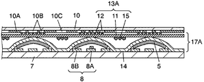
- the switch according to the present embodiment has a movable contact body 17A instead of the movable contact body 17 in FIG. 3 of the first embodiment.
- the movable contact body 17A has a light guide sheet 13A instead of the light guide sheet 13 in the first embodiment.
- 13 A of light guide sheets have the base material 11, the light emission part 12, and the light guide part 15. FIG. That is, it is the same as the light guide sheet 13 that a plurality of uneven light emitting portions 12 are provided at predetermined locations on the upper surface of the film-like substrate 11.
- a plurality of light guide portions 15 that are substantially band-like and light transmissive are provided on the lower surface of the base material 11 between the plurality of light emitting portions 12.
- the light guide part 15 is provided in the position except the arrangement
- the light guide portion 15 is provided not on the upper surface of the cover sheet 14 but on the lower surface of the base material 11.
- the other configuration is the same as that of the first embodiment shown in FIG.
- the material and formation method of the light guide part 15 are the same as Embodiment 1, description is abbreviate
- the lower surface of the light guide part 15 is formed in an uneven shape.
- the light guide 15 is illustrated as an integral part including the adhesive for pasting. These characteristics are also the same as in the first embodiment.
- the light guide part 15 is not limited to the strip
- the light guide unit 15 is disposed at a position between the light emitting units 12 on the upper surface of the base material 11. It is good also as a provided structure.
- the configuration in which the cover sheet 14 with the plurality of movable contacts 5 attached to the lower surface is attached to the lower surface of the light guide sheet 13A has been described.
- the cover sheet 14 may be eliminated, and the plurality of movable contacts 5 may be directly attached to the lower surface of the light guide sheet 13A. In this configuration, the number of components is reduced, and the movable contact body is simpler and less expensive.
- the light transmissive light guide part 15 is provided at a position between the light emitting parts 12 where the movable contact 5 is disposed. Even in this configuration, in addition to the light emission of the light emitting units 12 of the light guide sheet 13A, the light guide unit 15 between them can emit light with different colors and time differences. Therefore, like the first embodiment, the movable contact body 17A that can perform various illuminations with a simple configuration can be manufactured. Also in this embodiment, the configuration shown in FIGS. 4 to 7 can be applied.
- the light-transmitting light guide portion is formed by forming a film-like sheet of a predetermined material into a predetermined shape and pasting it on the cover sheet 14 or the substrate 11 with an adhesive or the like.
- the light guide section itself may be formed by printing.
- you may form the light guide part from which these differ in a refractive index in the inner side of the cover sheet 14 or the base material 11 by two-color molding etc.
- the present invention can also be implemented by these manufacturing methods. Even in such a manufacturing method, the light guides may be connected or partially changed in thickness. Further, they may be emitted with different colors or timings, or may be emitted with the same color.
- the movable contact body according to the present invention can produce a movable contact body and a switch capable of various illuminations with a simple configuration. These are useful for operating various electronic devices.
Landscapes
- Push-Button Switches (AREA)
Abstract
Priority Applications (3)
| Application Number | Priority Date | Filing Date | Title |
|---|---|---|---|
| US12/668,910 US8164015B2 (en) | 2008-02-28 | 2009-02-20 | Movable contact unit and switch using the same |
| JP2010500550A JP5104941B2 (ja) | 2008-02-28 | 2009-02-20 | 可動接点体とこれを用いたスイッチ |
| CN2009801007575A CN101884081B (zh) | 2008-02-28 | 2009-02-20 | 可动触点体和采用该可动触点体的开关 |
Applications Claiming Priority (2)
| Application Number | Priority Date | Filing Date | Title |
|---|---|---|---|
| JP2008-047047 | 2008-02-28 | ||
| JP2008047047 | 2008-02-28 |
Publications (1)
| Publication Number | Publication Date |
|---|---|
| WO2009107344A1 true WO2009107344A1 (fr) | 2009-09-03 |
Family
ID=41015751
Family Applications (1)
| Application Number | Title | Priority Date | Filing Date |
|---|---|---|---|
| PCT/JP2009/000722 Ceased WO2009107344A1 (fr) | 2008-02-28 | 2009-02-20 | Corps de contact mobile et commutateur associé |
Country Status (4)
| Country | Link |
|---|---|
| US (1) | US8164015B2 (fr) |
| JP (1) | JP5104941B2 (fr) |
| CN (1) | CN101884081B (fr) |
| WO (1) | WO2009107344A1 (fr) |
Families Citing this family (1)
| Publication number | Priority date | Publication date | Assignee | Title |
|---|---|---|---|---|
| TWM448778U (zh) * | 2012-11-02 | 2013-03-11 | Darfon Electronics Corp | 保護蓋及鍵盤 |
Citations (4)
| Publication number | Priority date | Publication date | Assignee | Title |
|---|---|---|---|---|
| JPH10144172A (ja) * | 1996-11-08 | 1998-05-29 | Casio Comput Co Ltd | 操作パネル |
| JP2004234958A (ja) * | 2003-01-29 | 2004-08-19 | Alps Electric Co Ltd | タッチパネル装置 |
| JP2007087749A (ja) * | 2005-09-21 | 2007-04-05 | Citizen Electronics Co Ltd | シートスイッチ、シートスイッチモジュール及びパネルスイッチ |
| JP2007324100A (ja) * | 2006-06-05 | 2007-12-13 | Citizen Electronics Co Ltd | シートスイッチモジュール |
Family Cites Families (14)
| Publication number | Priority date | Publication date | Assignee | Title |
|---|---|---|---|---|
| US6590174B2 (en) * | 2001-03-30 | 2003-07-08 | Visteon Global Technologies, Inc. | Switch assembly having diffused illumination |
| JP2002352657A (ja) * | 2001-05-25 | 2002-12-06 | Shin Etsu Polymer Co Ltd | 押釦スイッチ用部材とその製造方法 |
| JP2004247103A (ja) * | 2003-02-12 | 2004-09-02 | Nec Corp | キーボタン照光装置及びこれを用いた携帯電子機器 |
| JP2005150034A (ja) * | 2003-11-19 | 2005-06-09 | Mitsumi Electric Co Ltd | スイッチユニット |
| JP4468096B2 (ja) * | 2004-07-20 | 2010-05-26 | ポリマテック株式会社 | キーシート及びキーシートの製造方法 |
| JP2006127799A (ja) * | 2004-10-26 | 2006-05-18 | Alps Electric Co Ltd | 板ばね付きシート及びこれを用いたスイッチ装置 |
| KR100689394B1 (ko) * | 2005-06-28 | 2007-03-02 | 삼성전자주식회사 | 휴대 장치용 키패드 어셈블리 |
| KR100651413B1 (ko) * | 2005-07-15 | 2006-11-29 | 삼성전자주식회사 | 키 패드 어셈블리 |
| TW200709243A (en) | 2005-08-19 | 2007-03-01 | Citizen Electronics | Sheet switch, sheet switch module and panel switch |
| JP2007122970A (ja) * | 2005-10-26 | 2007-05-17 | Alps Electric Co Ltd | 板ばね付きシート、及び入力装置 |
| JP2007134082A (ja) * | 2005-11-08 | 2007-05-31 | Alps Electric Co Ltd | 板ばね付きシート、及び入力装置 |
| JP2007299588A (ja) * | 2006-04-28 | 2007-11-15 | Alps Electric Co Ltd | 押釦スイッチおよびこの押釦スイッチの作製に用いられる接点ばね付きシート |
| CN101192478B (zh) * | 2006-12-01 | 2010-08-11 | 深圳富泰宏精密工业有限公司 | 背光键盘 |
| WO2008072577A1 (fr) * | 2006-12-11 | 2008-06-19 | Alps Electric Co., Ltd. | Dispositif d'éclairage ; dispositif d'entrée présentant une fonction d'éclairage et muni dudit dispositif d'éclairage |
-
2009
- 2009-02-20 WO PCT/JP2009/000722 patent/WO2009107344A1/fr not_active Ceased
- 2009-02-20 US US12/668,910 patent/US8164015B2/en not_active Expired - Fee Related
- 2009-02-20 JP JP2010500550A patent/JP5104941B2/ja not_active Expired - Fee Related
- 2009-02-20 CN CN2009801007575A patent/CN101884081B/zh not_active Expired - Fee Related
Patent Citations (4)
| Publication number | Priority date | Publication date | Assignee | Title |
|---|---|---|---|---|
| JPH10144172A (ja) * | 1996-11-08 | 1998-05-29 | Casio Comput Co Ltd | 操作パネル |
| JP2004234958A (ja) * | 2003-01-29 | 2004-08-19 | Alps Electric Co Ltd | タッチパネル装置 |
| JP2007087749A (ja) * | 2005-09-21 | 2007-04-05 | Citizen Electronics Co Ltd | シートスイッチ、シートスイッチモジュール及びパネルスイッチ |
| JP2007324100A (ja) * | 2006-06-05 | 2007-12-13 | Citizen Electronics Co Ltd | シートスイッチモジュール |
Also Published As
| Publication number | Publication date |
|---|---|
| CN101884081A (zh) | 2010-11-10 |
| CN101884081B (zh) | 2013-02-13 |
| JPWO2009107344A1 (ja) | 2011-06-30 |
| US20100187077A1 (en) | 2010-07-29 |
| JP5104941B2 (ja) | 2012-12-19 |
| US8164015B2 (en) | 2012-04-24 |
Similar Documents
| Publication | Publication Date | Title |
|---|---|---|
| US7619173B2 (en) | Light guide sheet and movable contact unit and switch using the same | |
| KR20080012777A (ko) | 발광 시트 모듈 | |
| WO2002095778A1 (fr) | Commutateur a boutons illumines | |
| JP2008152951A (ja) | シートスイッチモジュール | |
| JP2009094036A (ja) | 可動接点体及びこれを用いたスイッチ | |
| JP2008305655A (ja) | 可動接点体及びこれを用いたスイッチ | |
| JP2008300254A (ja) | 可動接点体及びこれを用いたスイッチ | |
| JP2009099298A (ja) | スイッチ | |
| US8025435B2 (en) | Light guide sheet and movable contact element using the same | |
| JP2004014284A (ja) | 照光スイッチシート及びこれを用いた照光ユニット | |
| US7718910B2 (en) | Movable contact assembly and switch using the same | |
| JP2010135160A (ja) | 導光シート及びこれを用いた可動接点体 | |
| JP5023971B2 (ja) | 導光機能付き可動接点体とそれを用いた入力装置 | |
| JP5104941B2 (ja) | 可動接点体とこれを用いたスイッチ | |
| JP2012043777A (ja) | 導光シート及びこれを用いた可動接点体 | |
| JP2010225346A (ja) | 導光シート及びこれを用いた可動接点体 | |
| JP2008243655A (ja) | 可動接点体およびそれを用いて構成した照光式パネルスイッチ | |
| JP2010129502A (ja) | 可動接点体及びこれを用いたスイッチ | |
| US8337028B2 (en) | Light guide sheet and movable contact assembly using the same | |
| JP5619369B2 (ja) | シートスイッチ | |
| JP5292981B2 (ja) | 可動接点体 | |
| JP2010027534A (ja) | 導光シート及びこれを用いた可動接点体 | |
| JP2011113699A (ja) | 可動接点体及びこれを用いたスイッチ | |
| JP2010244794A (ja) | 可動接点体及びこれを用いたスイッチ | |
| JP2010027535A (ja) | 導光シート及びこれを用いた可動接点体 |
Legal Events
| Date | Code | Title | Description |
|---|---|---|---|
| WWE | Wipo information: entry into national phase |
Ref document number: 200980100757.5 Country of ref document: CN |
|
| ENP | Entry into the national phase |
Ref document number: 2010500550 Country of ref document: JP Kind code of ref document: A |
|
| 121 | Ep: the epo has been informed by wipo that ep was designated in this application |
Ref document number: 09715047 Country of ref document: EP Kind code of ref document: A1 |
|
| WWE | Wipo information: entry into national phase |
Ref document number: 12668910 Country of ref document: US |
|
| NENP | Non-entry into the national phase |
Ref country code: DE |
|
| 122 | Ep: pct application non-entry in european phase |
Ref document number: 09715047 Country of ref document: EP Kind code of ref document: A1 |