WO2009107347A1 - 受信装置、集積回路及び受信方法 - Google Patents
受信装置、集積回路及び受信方法 Download PDFInfo
- Publication number
- WO2009107347A1 WO2009107347A1 PCT/JP2009/000745 JP2009000745W WO2009107347A1 WO 2009107347 A1 WO2009107347 A1 WO 2009107347A1 JP 2009000745 W JP2009000745 W JP 2009000745W WO 2009107347 A1 WO2009107347 A1 WO 2009107347A1
- Authority
- WO
- WIPO (PCT)
- Prior art keywords
- interference
- unit
- data
- symbol
- vector
- Prior art date
- Legal status (The legal status is an assumption and is not a legal conclusion. Google has not performed a legal analysis and makes no representation as to the accuracy of the status listed.)
- Ceased
Links
Images


Classifications
-
- H—ELECTRICITY
- H04—ELECTRIC COMMUNICATION TECHNIQUE
- H04L—TRANSMISSION OF DIGITAL INFORMATION, e.g. TELEGRAPHIC COMMUNICATION
- H04L25/00—Baseband systems
- H04L25/02—Details ; arrangements for supplying electrical power along data transmission lines
- H04L25/03—Shaping networks in transmitter or receiver, e.g. adaptive shaping networks
- H04L25/03006—Arrangements for removing intersymbol interference
- H04L25/03159—Arrangements for removing intersymbol interference operating in the frequency domain
-
- H—ELECTRICITY
- H04—ELECTRIC COMMUNICATION TECHNIQUE
- H04L—TRANSMISSION OF DIGITAL INFORMATION, e.g. TELEGRAPHIC COMMUNICATION
- H04L25/00—Baseband systems
- H04L25/02—Details ; arrangements for supplying electrical power along data transmission lines
- H04L25/03—Shaping networks in transmitter or receiver, e.g. adaptive shaping networks
- H04L25/03006—Arrangements for removing intersymbol interference
- H04L25/03821—Inter-carrier interference cancellation [ICI]
-
- H—ELECTRICITY
- H04—ELECTRIC COMMUNICATION TECHNIQUE
- H04L—TRANSMISSION OF DIGITAL INFORMATION, e.g. TELEGRAPHIC COMMUNICATION
- H04L25/00—Baseband systems
- H04L25/02—Details ; arrangements for supplying electrical power along data transmission lines
- H04L25/03—Shaping networks in transmitter or receiver, e.g. adaptive shaping networks
- H04L25/03006—Arrangements for removing intersymbol interference
- H04L2025/0335—Arrangements for removing intersymbol interference characterised by the type of transmission
- H04L2025/03375—Passband transmission
- H04L2025/03414—Multicarrier
-
- H—ELECTRICITY
- H04—ELECTRIC COMMUNICATION TECHNIQUE
- H04L—TRANSMISSION OF DIGITAL INFORMATION, e.g. TELEGRAPHIC COMMUNICATION
- H04L27/00—Modulated-carrier systems
- H04L27/26—Systems using multi-frequency codes
- H04L27/2601—Multicarrier modulation systems
- H04L27/2647—Arrangements specific to the receiver only
Definitions
- the present invention relates to a technique for removing an error caused by at least one of inter-symbol interference and inter-carrier interference from a transmission signal obtained by frequency division multiplexing a plurality of modulated carriers.
- Orthogonal frequency division multiplexing is adopted as a transmission method of digital terrestrial broadcasting and wireless LAN (Local Area Network).
- the OFDM method is a method with high frequency utilization efficiency because it is a method of closely arranging a plurality of carriers while maintaining orthogonality. Further, in the OFDM method, since the symbol length can be set long, this method is a method resistant to inter-symbol interference caused by a plurality of incoming waves.
- guard interval technology is widely used as the OFDM technology. This adds a part after the effective symbol as a guard interval to the front of the effective symbol, and if the delay time of the delayed wave with respect to the main wave is within the guard interval time width, interference relating to intersymbol interference due to the delayed wave It is possible to avoid components and apply a Fast Fourier Transform (FFT). By this, the receiver can demodulate the received OFDM transmission signal without deterioration.
- FFT Fast Fourier Transform
- ISI inter-symbol interference
- ICI inter-carrier interference
- a single frequency network (SFN) is used, and the transmission station is installed so that the delay time of the delay wave falls within the time width of the guard interval.
- SFN single frequency network
- the transmission station is installed so that the delay time of the delay wave falls within the time width of the guard interval.
- a delay wave having a delay time exceeding the guard interval time width arrives due to reflections in mountains, buildings, and the like.
- intersymbol interference and intercarrier interference make it difficult for the receiver to correctly demodulate the received OFDM transmission signal, and the reception quality is significantly degraded.
- the demodulation data in the frequency domain is calculated by applying FFT to the OFDM transmission signal in the time domain, the channel response data in the frequency domain is estimated based on the demodulated data, and the inverse fast Fourier transform is performed to the channel response data in the frequency domain
- a channel response signal in the time domain is calculated by applying Inverse Fast Fourier Transform (IFFT).
- IFFT Inverse Fast Fourier Transform
- Waveform equalization is performed on the OFDM transmission signal in the time domain based on the transmission channel response signal in the time domain, interference components related to intersymbol interference and intercarrier interference are estimated, and interference components are removed from the OFDM transmission signal.
- Patent Document 2 Although there is another method disclosed in Patent Document 2, interference components related to inter-symbol interference and inter-carrier interference due to preceding waves arriving prior to the main wave can not be estimated and removed.
- Patent Document 2 Japanese Patent Application Publication No. 2007-006067 JP, 2004-289475, A
- the present invention is a receiving apparatus that enables removal of an error component related to at least one of inter-symbol interference and inter-carrier interference from a transmission signal obtained by frequency division multiplexing a plurality of modulated carriers. It is an object to provide an integrated circuit and a receiving method.
- a receiving apparatus is a receiving apparatus that receives a transmission signal obtained by multiplexing a plurality of modulated carriers, and demodulates the transmission signal.
- an equalization unit for calculating equalization data in a frequency domain, and interference representing an interference component related to at least one of intersymbol interference and intercarrier interference based on the equalization data and the transmission path response data for each symbol.
- an interference removing unit that calculates data and performs a process of removing the interference component on the demodulated data based on the interference data.
- the integrated circuit of the present invention is an integrated circuit that receives a transmission signal in which a plurality of modulated carriers are multiplexed and demodulates the transmission signal, and the transmission signal in the received time domain is symbolized in each symbol.
- a converter circuit for converting into demodulated data in the frequency domain, and estimating channel response data in the frequency domain based on the demodulated data, and equalizing the demodulated data based on the channel response data thus estimated; Calculating equalization data representing at least one of intersymbol interference and intercarrier interference based on the equalization data and the channel response data for each symbol, and an equalization circuit for calculating equalization data;
- an interference removal circuit for removing the interference component on the demodulated data based on the interference data.
- a receiving method is a receiving method performed in a receiving apparatus that receives a transmission signal in which a plurality of modulated carriers are multiplexed and demodulates the transmission signal, and Converting the transmission signal into demodulated data in the frequency domain for each symbol, estimating transmission channel response data in the frequency domain based on the demodulated data, and calculating the demodulated data based on the transmission channel response data estimated Calculating an equalization data in a frequency domain and calculating an interference component relating to at least one of intersymbol interference and intercarrier interference based on the equalization data and the channel response data for each symbol. Calculating interference data, and performing an interference removal process on the demodulated data based on the interference data. That.
- the above receiving apparatus, integrated circuit, and receiving method calculation and removal of interference components are performed in the frequency domain subsequent to the conversion unit that converts the transmission signal in the time domain into demodulated data in the frequency domain.
- the reception quality can be improved by removing the effects of intersymbol interference and intercarrier interference while suppressing the increase of.
- the interference removal unit deduces that delay processing is performed on the equalization data corresponding to one symbol, assuming that N is a number larger than 1 and Tu is a time width of an effective symbol period.
- a delay upsampling unit that performs sample processing to generate and output first equalization data having a discrete frequency interval of 1 / (N ⁇ Tu), and up the transmission path response data corresponding to the one symbol
- An up-sampling unit that performs sample processing to generate first channel response data with discrete frequency intervals of 1 / (N ⁇ Tu), and the first equalization data and the first channel response data for each carrier
- a multiplication unit that performs multiplication to generate first demodulation data, and filter processing based on a predetermined pass characteristic on the first demodulation data to generate intersymbol interference due to a delay wave from the first demodulation data
- the first interference component is extracted, an extraction unit that generates first interference data representing the first interference component, and the first interference data is subjected to down-sampling processing to the interference data representing
- the adjacent signal components when the first demodulation data is viewed in the time domain do not overlap, it becomes possible to independently extract the first interference component related to the inter-symbol interference due to the delayed wave, The ability to remove inter-symbol interference due to delayed waves can be improved.
- the interference component generation unit performs phase rotation processing based on a value obtained by multiplying the time width of a guard interval period by ⁇ 1 for each carrier, in addition to the downsampling processing for the first interference data. It may be applied.
- the interference removing unit upsamples the equalization data corresponding to one symbol, assuming that N is a number larger than 1 and Tu is a time width of an effective symbol period. And performing up-sampling processing on the transmission path response data corresponding to the one symbol, and a first up-sampling unit that generates first equalization data having a discrete frequency interval of 1 / (N ⁇ Tu).
- a second up-sampling unit that generates first transmission path response data having a discrete frequency interval of 1 / (N ⁇ Tu); and multiplying the first equalization data and the first transmission path response data for each carrier
- a multiplication unit for generating first demodulation data, and filtering processing based on a predetermined pass characteristic on the first demodulation data to obtain first interference components relating to inter-carrier interference due to delay waves from the first demodulation data To generate first interference data representing the first interference component, and down-sampling processing on the first interference data to generate the interference data representing the interference component.
- a removal unit that adds the interference data to the demodulated data corresponding to the one symbol.
- the adjacent signal components when the first demodulation data is viewed in the time domain do not overlap, it becomes possible to independently extract the first interference component related to the inter-carrier interference due to the delay wave, The ability to remove inter-symbol interference due to delayed waves can be improved.
- the interference removing unit performs phase rotation processing based on a time interval of a guard interval period for each carrier with respect to the equalized data or the first equalized data corresponding to the one symbol.
- the first up-sampling unit further includes a phase rotation unit that generates second equalization data, and the first up-sampling unit performs the phase rotation process on the equalization data when the phase rotation unit performs the phase rotation process on the equalization data.
- the multiplication is performed.
- the unit multiplies the second equalized data and the first transmission path response data instead of the first equalized data for each carrier to generate the first demodulated data, and the interference component generation unit 1st interference
- the interference component generation unit 1st interference
- it may be a phase rotation processing based on the value obtained by multiplying by -1 times the width of the guard interval period for each carrier subjected.
- the interference removing unit performs delay processing on the equalized data corresponding to one symbol and outputs delayed equalized data;
- a first up-sampling unit that performs up-sampling processing on equalized data to generate first differential equalized data having a discrete frequency interval of 1 / (N ⁇ Tu); and the transmission path corresponding to the one symbol
- a second up-sampling unit that performs up-sampling processing on response data to generate first channel response data having a discrete frequency interval of 1 / (N ⁇ Tu), the first differential equalization data, and the first differential equalization data transmission
- Inter-symbol interference due to a delay wave from the differential demodulation data by performing a filter process based on a predetermined passing characteristic on the differential demodulation data by multiplying the path response data by each carrier to generate differential
- the circuit scale is reduced while intersymbol interference due to delayed waves is achieved. It is possible to remove both interference components related to the inter-carrier interference and the inter-carrier interference.
- the interference removing unit performs phase rotation processing based on a time interval of a guard interval period for each carrier with respect to the equalized data corresponding to the one symbol to generate first equalized data.
- the differential unit further includes a phase rotation unit, and the differential unit uses the first equalization data instead of the equalization data corresponding to the one symbol to generate the first equalization data from the delay equalization data.
- the subtraction is performed to generate the differential equalization data representing the subtraction result, and the interference component generation unit adds the first interference data to the down-sampling processing, and the time width of the guard interval period is ⁇ 1 for each carrier.
- a phase rotation process may be performed based on a value obtained by multiplying.
- the interference removing unit performs filter processing based on a predetermined pass characteristic on the differentially demodulated data, and relates to intersymbol interference due to the preceding wave and intercarrier interference due to the preceding wave from the differentially demodulated data.
- a first extraction unit that extracts a second interference component and generates second interference data representing the second interference component, and performs down-sampling processing on the second interference data to generate intersymbol interference and leading by preceding waves.
- a first interference component generation unit that generates the third interference data representing a third interference component related to inter-carrier interference due to waves, and a delay process is performed on the first demodulation data obtained as a result of the processing by the removal unit
- a first delay unit that outputs the first delay demodulation data, and a first removal unit that adds the first delay demodulation data and the third interference data.
- delay processing and up-sampling processing are performed on the channel response data corresponding to the one symbol to generate second channel response data having a discrete frequency interval of 1 / (N ⁇ Tu).
- a first multiplication unit for generating first differential demodulation data by multiplying the first differential equalization data and the second transmission path response data for each carrier to generate a first differential demodulation data;
- the differential demodulation data is subjected to filter processing based on a predetermined pass characteristic to extract intersymbol interference due to the preceding wave and a second interference component related to intercarrier interference due to the preceding wave from the first differential demodulation data, and the second A first extraction unit for generating second interference data representing an interference component; and performing down-sampling processing on the second interference data to generate inter-symbol interference due to a preceding wave and A first interference component generation unit that generates the third interference data representing a third interference component related to inter-rear interference; delay processing is performed on the first demodulation data obtained as a result of processing by the
- the interference removing unit divides the supplied first delay demodulation data by the channel response data corresponding to one symbol to generate first equalization data;
- a first interference component related to inter-symbol interference due to a delayed wave is calculated based on one equalization data and the channel response data corresponding to the one symbol, and the equalization data corresponding to the one symbol and the one Calculating a second interference component related to inter-carrier interference due to a delayed wave based on the transmission path response data corresponding to the symbol, and subtracting the second interference component from the first interference component to calculate the interference component;
- An interference component generation unit for generating the interference data;
- a subtraction unit for subtracting the interference data from the demodulation data corresponding to the one symbol; and outputting first demodulation data;
- Said first delay demodulated data for the next symbol may be provided with a delay unit supplied to the division unit performs a delay process on tone data.
- the interference removing unit converts the equalized data in the frequency domain into an equalized signal in the time domain, converts the transmission line response data in the frequency domain into a transmission line signal in the time domain, and An interference signal representing the interference component may be calculated based on the equalized signal and the transmission path signal, and the interference component removal processing may be performed on the demodulated data based on the interference signal.
- the above receiving apparatus further includes a selection unit which compares the reception quality of the demodulation data with the first demodulation data obtained by the interference removal unit and which selects the better one of the reception quality. You may do so.
- the demodulation data from which the interference component is not removed is selected, and the degradation of the reception quality due to the interference removal is It can be avoided.
- the interference removal unit may perform hard removal processing on the equalized data to perform the removal processing.
- the estimation error of the equalization data can be reduced, the reception quality can be further improved.
- the above receiving apparatus may include a processing block including the equalization unit and the interference removal unit connected in multiple stages in series.
- the interference removal process is repeated multiple times, the reception quality can be further improved.
- a receiving apparatus is a receiving apparatus that receives a transmission signal in which a plurality of modulated carriers are multiplexed, and demodulates the transmission signal, and the transmission signal in the received time domain is symbolized in each symbol.
- Interference data representing an interference component relating to at least one of intersymbol interference and intercarrier interference is calculated based on the data and the delayed transmission path response data supplied, and the interference on the demodulated data is calculated based on the interference data.
- An interference removing unit that generates first demodulation data by performing a component removal process, and estimating and estimating channel response data in a frequency domain based on the first demodulation data.
- a delay unit that supplies response data to the division unit and the interference removal unit.
- the interference component is calculated and removed in the frequency domain subsequent to the conversion unit that converts the transmission signal in the time domain into demodulated data in the frequency domain, the inter-symbol interference is suppressed while the increase in circuit size is suppressed.
- the reception quality can be improved by removing the influence of inter-carrier interference and inter-carrier interference.
- channel response data is estimated using the first demodulation data generated by performing an interference component removal process, and the channel response data is fed back to calculate interference data based on interference data calculated. Since the first demodulation data is generated by performing interference component removal processing on the demodulation data, the transmission path response data has an effect of repeatedly removing the interference component, and the reception quality can be improved.
- a receiving apparatus is a receiving apparatus that receives a transmission signal in which a plurality of modulated carriers are multiplexed, and demodulates the transmission signal, and the transmission signal in the received time domain is symbolized in each symbol.
- a converter for converting into demodulated data in the frequency domain, and for each symbol, subtracting the delayed interference data representing the interference component related to the intersymbol interference due to the delayed wave supplied from the demodulated data to generate first demodulated data
- a transmission path response data in a frequency domain is estimated based on the first demodulation data, and the first demodulation data is equalized based on the estimated transmission path response data, and so on.
- a second interference removing unit that generates interference data representing a minute and performs interference removal processing on the first demodulated data, and performs delay processing on the interference data to generate the delayed interference data for the next symbol
- a delay unit that supplies the first interference removal unit.
- the interference component is calculated and removed in the frequency domain subsequent to the conversion unit that converts the transmission signal in the time domain into demodulated data in the frequency domain, the inter-symbol interference is suppressed while the increase in circuit size is suppressed.
- the reception quality can be improved by removing the influence of inter-carrier interference and inter-carrier interference.
- FIG. 4 is a block diagram of an equalization unit 14 of FIG. 3;
- FIG. 4 is a block diagram of an interference removal unit 15 of FIG. 3;
- (A)-(s) is a figure for demonstrating the processing content of the interference removal part 15 of FIG. (A) is a figure for demonstrating the pass band of the filter of the extraction part 57 of FIG.
- (b) is a figure for demonstrating the pass band of the filter of the extraction part 84 of FIG.
- the block diagram of the receiver 1b of 3rd Embodiment. (A)-(g) is a figure for demonstrating the processing content of the receiver 1b of FIG.
- FIG. 18 is a configuration diagram of a reception device 1h according to a ninth embodiment.
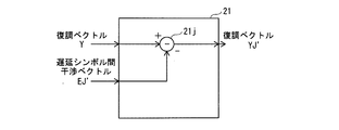
- FIG. 24 is a block diagram of the interference removal unit 21 of FIG. 23;
- FIG. 24 is a block diagram of the interference removal unit 23 of FIG. 23;
- FIG. 18 is a configuration diagram of an interference removal unit 15k according to a twelfth embodiment.
- the OFDM transmission signal is one of multicarrier transmission methods, and is for terrestrial digital broadcasting (DVB-T / H, ISDB-T, etc.), wireless LAN (IEEE 802.11a / g, etc.), Wi-MAX (IEEE 802. 16) It will be used or will be used in a wide range of product fields such as next-generation mobile communication.
- FIG. 1 schematically shows an OFDM transmission signal for one symbol, and the horizontal axis in FIG. 1 shows time.
- a time width of one symbol is Ts, and this time width Ts is referred to as a "symbol period”.
- the symbol period Ts consists of a period of time width Tu called “effective symbol period” and a period of time width Tg called “guard interval period”.
- the OFDM transmission signal is a signal obtained by digital modulation on a plurality of carriers for each symbol and multiplexing.
- the frequencies of the plurality of carriers are in a frequency relationship orthogonal to each other in the effective symbol period Tu.
- This frequency relationship is a relationship in which the frequency interval between any two carriers is an integral multiple of the reciprocal (1 / Tu) of the effective symbol period Tu. Therefore, the OFDM transmission signal becomes a signal having periodicity in the effective symbol period Tu, and the OFDM transmission signal transmitted in the guard interval period Tg copies the OFDM transmission signal transmitted in the time width Tg behind the effective symbol period Tu. It will be done.
- An OFDM transmission signal transmitted in a guard interval period Tg is called a cyclic prefix.
- an incoming wave with the highest reception level is referred to as a "principal wave”
- an incoming wave that precedes the main wave is referred to as a “preceding wave”
- an incoming wave that lags behind the main wave is referred to It is called “delayed wave”.
- FIG. 2 a case in which one delayed wave arrives at the receiving apparatus with a time delay greater than the guard interval period Tg with respect to the main wave as an example.
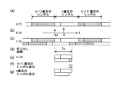
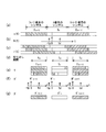
- FIG. 2 (a) to FIG. 2 (g) are diagrams for explaining the outline of inter-symbol interference and inter-carrier interference due to delayed waves, and the horizontal axis in each of FIGS. 2 (a) to 2 (g). Indicates time.
- FIG. 2 (a) schematically shows the OFDM transmission signal s (t) for a plurality of symbols transmitted continuously, and the transmitting station transmits the OFDM transmission signal continuously for a plurality of symbols.
- the OFDM transmission signal s n (t) of the focused n-th symbol is the OFDM transmission signal s (n-1) (t) and (n-1) -th symbol adjacent to it.
- the left hatching (rightward) of the OFDM transmission signal s (n-1) (t) of the (n-1) th symbol The pattern of the diagonally sloping shoulders is expressed by applying the pattern of the right diagonal lines (hatched lines) to the OFDM transmission signal s (n + 1) (t) of the (n + 1) th symbol.
- FIG. 2 (b) schematically shows a transmission path response signal h (t) indicating the transmission path response, which is represented by the relative time difference between the plurality of incoming waves arriving at the receiving apparatus and the reception level.
- the transmission line response signal h (t) shown in FIG. 2 (b) may be called a delay profile.
- the time difference td in which two incoming waves have arrived is larger than the guard interval period Tg is targeted.
- FIG. 2C schematically shows the OFDM transmission signal r (t) received by the receiving apparatus.
- the first arriving wave principal wave
- the arriving wave delayed wave
- Received in state. 2 (e) and 2 (g) are similarly displayed in an overlapping manner.
- the signal components derived from the OFDM transmission signal s (n-1) (t) are hatched with left hatching, and the signal components derived from the OFDM transmission signal s (n + 1) (t) In the right hatched pattern.
- the pattern is similarly applied and represented also about FIG.2 (e) and FIG.2 (f).
- the receiving apparatus that receives the OFDM transmission signal extracts and demodulates the OFDM transmission signal for the time width Tu of the effective symbol period from the received OFDM transmission signal r (t) for each symbol. In the n-th symbol, the receiving apparatus performs the OFDM transmission shown in FIG. 2 (e) corresponding to the time width Tu of the effective symbol period shown in FIG. 2 (c) to the OFDM transmission signal r (t). Cut out the signal r n (t).
- FIG. 2 (f) is a signal derived from the OFDM transmission signal s (n-1) (t) of the (n-1) -th symbol included in the OFDM transmission signal r n (t) shown in FIG. 2 (e) Represents a component.
- a signal component derived from the OFDM transmission signal s (n-1) (t) of the (n-1) th symbol relates to intersymbol interference due to a delay wave in the OFDM transmission signal r n (t) of the nth symbol It is an interference component.
- the interference component related to the intersymbol interference due to the delayed wave in the OFDM transmission signal r n (t) of the nth symbol is the delayed wave related to the OFDM transmission signal s (n ⁇ 1) (t) of the (n ⁇ 1) th symbol
- the signal component of the (td-Tg) period which goes back in time from the end of.
- FIG. 2 (g) shows signal components derived from the OFDM transmission signal s n (t) of the n-th symbol included in the OFDM transmission signal r n (t) shown in FIG. 2 (e).
- the time width of the signal component of the delayed wave derived from the OFDM transmission signal s n (t) of the nth symbol included in the OFDM transmission signal r n (t) is the time width Tu of the effective symbol period It is understood that it is less than.
- the time width of the signal component of this delayed wave is less than the time width Tu of the effective symbol period, orthogonality among a plurality of carriers forming the OFDM transmission signal r n (t) can not be maintained, and Inter-carrier interference will occur when demodulating each one.
- the interference component related to inter-carrier interference due to delayed waves in the OFDM transmission signal r n (t) of the nth symbol is the time td before the end of the delayed wave for the OFDM transmission signal s n (t) of the nth symbol It is a signal component of (td ⁇ Tg) period from the position.
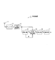
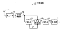
- FIG. 3 is a block diagram of the receiving device 1 according to the present embodiment
- FIGS. 4 (a) to 4 (g) are diagrams for explaining the processing contents of the receiving device 1 of FIG.
- the receiver 1 includes an antenna 11, a tuner 12, an OFDM demodulator 13, an equalizer 14, an interference remover 15, an equalizer 16, and a decoder 17.
- the antenna 11 receives an OFDM transmission signal emitted from a transmitting station (not shown) and supplies the received OFDM transmission signal to the tuner 12.
- the tuner 12 selects an OFDM transmission signal r (t) of a desired channel from the OFDM transmission signal supplied from the antenna 11, and outputs the selected OFDM transmission signal r (t) to the OFDM demodulation unit 13.
- FIG. 4 (a) schematically shows the OFDM transmission signal s (t) emitted from the transmitting station.
- FIG. 4 (b) schematically shows the transmission path response signal h (t).
- FIG. 4C schematically shows the OFDM transmission signal r (t) received and selected by the receiving device 1.
- X (n-1) , X n and X (n + 1) in FIG. 4A are the (n-1) th symbol, the nth symbol and the (n + 1) th symbol, respectively.
- the OFDM transmission signal s (n-1) (t) of the (n-1) th symbol is hatched with a left diagonal pattern
- the OFDM transmission signal s (n + 1) (t) of the (n + 1) th symbol is It is shown with a pattern of right diagonal lines.
- FIG. 4 (c) the signal components derived from the OFDM transmission signal s (n-1) (t) are hatched with left hatching, and the signal components derived from the OFDM transmission signal s (n + 1) (t) In the right hatched pattern.
- the OFDM demodulation unit 13 transmits the OFDM transmission signal r (t) shown in FIG. 4 (c) to FIG. 4 (d) supplied from the tuner 12 for each symbol according to the symbol synchronization signal generated by the symbol synchronization unit (not shown).
- the OFDM transmission signal corresponding to the time width Tu of the effective symbol period shown is extracted, and discrete Fourier transform is performed on the extracted OFDM transmission signal.
- the OFDM demodulation unit 13 supplies the demodulation vector Y in the frequency domain obtained as a result of the discrete Fourier transform to the equalization unit 14 and the interference removal unit 15. Note that discrete Fourier transform can be calculated at high speed using fast Fourier transform.
- 4E schematically shows the demodulation vector Y in the frequency domain output from the OFDM demodulator 13 by converting it into a signal in the time domain.
- symbols Y (n-1) , Y n and Y (n + 1) in FIG. 4 (e) are the (n-1) th symbol, the nth symbol and the (n + 1) th symbol, respectively.
- the signal components derived from the OFDM transmission signal s (n-1) (t) of the (n-1) th symbol are left hatched in the signal component, and the OFDM transmission signal s (n + 1 ) of the (n + 1) th symbol is The signal components derived from (t) are indicated by hatching a right diagonal line.
- the configuration from the antenna 11 to the OFDM demodulation unit 13 described above is the same as the configuration used in a general receiver for receiving an OFDM transmission signal, and the detailed description will not be made.
- the equalization unit 14 estimates a channel response vector H ′ from the demodulation vector Y supplied from the OFDM demodulation unit 13 and equalizes the demodulation vector Y based on the estimated channel response vector H ′ to equalize the equalization vector X 'Is calculated, and the transmission path response vector H' and the equalization vector X 'are supplied to the interference removing unit 15.
- FIG. 4F schematically shows the channel response vector H ′ in the frequency domain output from the equalizer 14 by converting it into a signal in the time domain
- the equalization vector X ′ in the frequency domain output from the unit 14 is converted into a signal in the time domain and schematically represented.
- H ' (n-1) , H' n and H ' (n + 1) in FIG. 4 (f) are the (n-1) th symbol, the nth symbol and the (n + 1) th, respectively.
- X ' (n-1) , X' n and X ' (n + 1) in FIG. 4 (g) are the (n-1) th symbol, the nth symbol and the (n + 1) th, respectively.
- the equalization vector X ′ output from the equalization unit 14 is a reproduction of the modulation vector X modulated on the transmission side by the transmission path equalization processing. However, in the presence of a delayed wave exceeding the guard interval period Tg, the equalization vector X ′ output from the equalization unit 14 is related to the intersymbol interference and intercarrier interference due to the delayed wave with respect to the modulation vector X. Interference component is included.
- the interference removal unit 15 uses the channel response vector H ′ supplied from the equalization unit 14 and the equalization vector X ′ to generate intersymbol symbols due to delayed waves included in the demodulation vector Y supplied from the OFDM demodulation unit 13. An interference vector representing an interference component relating to interference and an interference vector representing an interference component relating to inter-carrier interference due to a delayed wave lacking in the demodulation vector Y are calculated. Then, the interference removing unit 15 subtracts the interference vector representing the interference component relating to the intersymbol interference due to the delay wave to the demodulation vector Y and adds the interference vector representing the interference component relating to the intercarrier interference due to the delay wave. Processing is performed, and the demodulation vector Y ′ obtained as a result of these processing is supplied to the equalization unit 16.
- the equalization unit 16 estimates a channel response vector H ′ ′ from the demodulation vector Y ′ supplied from the interference removal unit 15, and equalizes and equalizes the demodulation vector Y ′ based on the estimated channel response vector H ′ ′.
- the vector X ′ ′ is calculated, and the equalization vector X ′ ′ is supplied to the decoding unit 17.
- the decoding unit 17 performs demapping processing on the equalization vector X ′ ′ supplied from the equalization unit 16 to determine a modulation vector X, and performs decoding processing such as error correction on the determination result. Determine and output.
- FIG. 5 is a block diagram of the equalization unit 14 of FIG.
- the configuration of the equalization unit 14 shown in FIG. 5 is a known configuration generally used for channel equalization in the terrestrial digital broadcasting system.
- the equalizer 16 in FIG. 3 can use substantially the same configuration as the configuration shown in FIG.
- the equalization unit 14 includes an SP extraction unit 31, an SP generation unit 32, a division unit 33, a symbol interpolation filter 34, a carrier interpolation filter 35, and a division unit 36.
- the demodulation vector Y output from the OFDM demodulation unit 13 is supplied to the SP extraction unit 31 and the division unit 36 in the equalization unit 14.
- N1 of (N1, N2) appended to each vector in the description of the equalization unit 14 represents a symbol number
- N2 represents a carrier number.
- the SP extraction unit 31 extracts a demodulation vector Y (n, k sp (n)) corresponding to the dispersed pilot from the demodulation vector Y (n, k) supplied from the OFDM demodulation unit 13 and extracts the extracted demodulation vector Y (n n, k sp (n)) is supplied to the dividing unit 33.
- K sp (n) represents the carrier number of the carrier corresponding to the distributed pilot in symbol number n.
- the SP generation unit 32 generates a reference vector SP (n, k sp (n)) having the same amplitude and the same phase as the modulation vector X (n, k sp (n)) generated on the transmission side, and generates the reference
- the vector SP (n, k sp (n)) is supplied to the dividing unit 33.
- the division unit 33 divides the demodulation vector Y (n, k sp (n)) supplied from the SP extraction unit 31 by the reference vector SP (n, k sp (n)) supplied from the SP generation unit 32,
- the division result is supplied to the symbol interpolation filter 34 as a transmission path response vector H '(n, k sp (n)).
- the symbol interpolation filter 34 performs interpolation processing in the symbol direction on the symbol-carrier plane using the channel response vector H ′ (n, k sp (n)) supplied from the division unit 33, and the carrier interpolation filter 35 Using the result of the interpolation process in the symbol direction by the symbol interpolation filter 34, the interpolation process is performed in the carrier direction on the symbol-carrier plane.
- the carrier interpolation filter 35 supplies the channel response vector H ′ (n, k) obtained as a result of the interpolation process in the carrier direction to the dividing unit 36 and the interference removing unit 15.
- the channel response vector H ′ output from the carrier interpolation filter 35 is a channel response vector for each carrier for each symbol.
- the division unit 36 divides the demodulation vector Y (n, k) supplied from the OFDM demodulation unit 13 by the channel response vector H ′ (n, k) supplied from the carrier interpolation filter 35, and equalizes the division result It supplies to the interference removal part 15 as vector X '(n, k).
- the equalization vector X ′ output from the division unit 36 is an equalization vector for each carrier for each symbol.
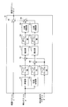
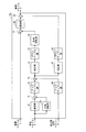
- FIG. 6 is a block diagram of the interference removal unit 15 of FIG. 3
- FIG. 7A to FIG. 7S are diagrams for explaining the processing contents of the interference removal unit 15 of FIG.
- the interference removal unit 15 includes a delay unit 51, an up-sampling unit 52, a phase rotation unit 53, an up-sampling unit 54, an up-sampling unit 55, a multiplication unit 56, an extraction unit 57, and a down-sampling unit 58.
- the demodulation vector Y output from the OFDM demodulation unit 13 is supplied to the subtraction unit 65 in the interference removal unit 15.
- the equalization vector X ′ output from the equalization unit 14 is supplied to the delay unit 51 and the phase rotation unit 53 in the interference removal unit 15, and the channel response vector H ′ output from the equalization unit 14 is an interference removal unit 15 are supplied to the up-sampling unit 55 in FIG.
- FIG. 7 (a) schematically shows, in the n-th symbol, the demodulation vector Y n in the frequency domain output by the OFDM demodulator 13 into a signal in the time domain, and (n-1)
- the signal components derived from the OFDM transmission signal s (n-1) (t) of the second symbol are indicated by hatching a left hatched pattern.
- FIG. 7 (b) schematically shows, in the n-th symbol, the equalization vector X ′ n in the frequency domain output from the equalization unit 14 as a signal in the time domain.
- FIG. 7C schematically shows the channel response vector H ′ n in the frequency domain output from the equalizer 14 in the n-th symbol, converted to a signal in the time domain.
- the demodulation vector Y n , the equalization vector X ′ n and the channel response vector H ′ n are obtained for each discrete frequency of a plurality of carriers used in OFDM transmission.
- the frequency of a plurality of carriers used in OFDM transmission is a discrete frequency of (1 / Tu) interval, where Tu is a time width of an effective symbol period. Therefore, when the demodulation vector Y n in the frequency domain, the equalization vector X ′ n, and the channel response vector H ′ n are represented by signals in the time domain, FIGS. 7 (a), 7 (b) and 7 (c). As shown in), it is represented by a repetitive signal having a period of time width Tu of the effective symbol period.
- the description of the configuration and operation of the interference removing unit 15 includes calculation of an interference component related to intersymbol interference due to delayed waves (hereinafter referred to as “delayed wave intersymbol interference component”) and intercarrier interference due to delayed waves. It divides into three of the calculation of the interference component concerned (hereinafter referred to as “delayed wave inter-carrier interference component”) and the interference removal process for removing the delayed wave inter-symbol interference component and the delayed wave inter-carrier interference component from the demodulation vector explain.
- the processing for removing the interference component related to intersymbol interference due to the delayed wave or the leading wave described later is processing for subtracting it from the demodulation vector, and the processing for removing the interference component related to intercarrier interference due to the delayed wave or leading wave It is a process to add it to the demodulation vector.
- the processing content of each part in the interference removal unit 15 when the demodulation vector Y n , the equalization vector X ′ n and the channel response vector H ′ n corresponding to the n-th symbol are supplied to the interference removal unit 15 An example will be described.
- the delay unit 51 delays the equalization vector X ′ supplied from the equalization unit 14 by a time corresponding to the processing period of one symbol, that is, one symbol, and outputs the delayed signal.
- the delay unit The equalized vector X ′ (n ⁇ 1) corresponding to the (n ⁇ 1) -th symbol is supplied to the up-sampling unit 52 from the 51st.
- 7D schematically shows the equalization vector X ′ (n ⁇ 1) in the frequency domain output from the delay unit 51 as a signal in the time domain.
- 7 (d), 7 (e), 7 (g), 7 (i), 7 (j) and 7 (k ) relate to the equalization vector X ' (n-1). In order to indicate that it is a signal component, it is shown by applying a hatching pattern to the left.
- the up-sampling unit 52 double-upsamples the equalization vector X ′ (n ⁇ 1) supplied from the delay unit 51 by 2 times, and obtains the equalization vector X ′ 2 (n ⁇ 1) obtained as a result of the up-sampling.
- the signal is supplied to the multiplication unit 56.
- FIG. 7E schematically shows the frequency domain equalization vector X ′ 2 (n ⁇ 1) output from the up-sampling unit 52 by converting it into a time domain signal.
- the equalization vector X ′ 2 (n ⁇ 1) is created by upsampling the equalization vector X ′ (n ⁇ 1) of which the discrete frequency interval is 1 / Tu to two times, the equalization vector is The interval of discrete frequencies of X ′ 2 (n ⁇ 1) is 1 / (2 ⁇ Tu).
- the equalization vector X ′ 2 (n ⁇ 1) in the frequency domain is represented by a signal in the time domain, it is a repetitive signal having a period twice the time width Tu of the effective symbol period. expressed.
- double up-sampling for example, is a half band filter generated by FIR (Finite Impulse Response) filter after inserting 0 between carriers for the equalization vector X ′ (n ⁇ 1) . It can be realized by passing it. Also, double upsampling performed by other components can be realized in the same manner. Note that up-sampling is a known technique, and thus will not be described in further detail.
- FIR Finite Impulse Response
- the amplifier sampling unit 55 up-samples the channel response vector H ′ n corresponding to the n-th symbol supplied from the equalization unit 14 by 2 times, and the channel response vector H ′ 2 obtained as a result of the up-sampling. n is supplied to the multiplication unit 56.
- FIG. 7F schematically shows the channel response vector H ′ 2 n in the frequency domain output from the up-sampling unit 55 by converting it into a signal in the time domain. Since the channel response vector H ′ 2 n is created by up-sampling the channel response vector H ′ n having a discrete frequency interval of 1 / T by 2 times, the channel response vector H ′ 2 n The interval between discrete frequencies is 1 / (2 ⁇ Tu). As shown in FIG. 7F, when the channel response vector H ′ 2 n in the frequency domain is represented by a signal in the time domain, it is represented by a repetitive signal having a period twice the time width Tu of the effective symbol period. .
- the multiplying unit 56 multiplies, for each carrier, the equalization vector X ′ 2 (n ⁇ 1) supplied from the up-sampling unit 52 and the channel response vector H ′ 2 n supplied from the up-sampling unit 55 to perform multiplication.
- the demodulation vector Y1 ′ 2 (n ⁇ 1) obtained as a result of the above is supplied to the extraction unit 57.
- FIG. 7 (g) schematically represents the demodulation vector Y1 ' 2 (n-1) in the frequency domain output from the multiplier 56 into a signal in the time domain, and the upper part shows the signal related to the main wave. The lower part is a signal component related to the delayed wave.
- the signal in the time domain shown in FIG. 7 (g) is a convolution of the signal shown in FIG. 7 (e) and the signal shown in FIG. 7 (f) in the time domain.
- the delay time of the delayed wave with respect to the main wave is obtained by upsampling the equalized vector X ′ (n ⁇ 1) and the channel response vector H ′ n by double and doubling.
- td is within the time width Tu of the effective symbol period, the left and right repetitive components separated by 2 ⁇ Tu do not interfere with each other.
- delayed wave intersymbol interference components included in the demodulation vector Y n can be independently observed by using the demodulation vector Y 1 ′ 2 (n ⁇ 1) .
- the extraction unit 57 is formed of, for example, an FIR filter, and has the pass characteristic of the pass band described below.
- the extraction unit 57 performs a filtering process on the demodulation vector Y1 ′ 2 (n ⁇ 1) supplied from the multiplication unit 56 to obtain a delay related to the demodulation vector Y n from the demodulation vector Y1 ′ 2 (n ⁇ 1).
- the inter-symbol interference component is extracted, an interference vector E1 ′ 2 n representing the extracted delayed wave inter-symbol interference component is generated, and the generated interference vector E1 ′ 2 n is supplied to the down-sampling unit 58.
- the delayed wave inter-symbol interference component extracted by the extraction unit 57 has the td time with respect to the main wave in the (n-1) th symbol among the signal components included in the demodulation vector Y1 ′ 2 (n ⁇ 1). It is a signal component of a (td ⁇ Tg) period which is backward in time from the end of the delayed delayed wave, and is a signal component related to a delayed wave intersymbol interference component included in the demodulation vector Y ′ n .
- FIG. 7H is a schematic diagram showing the pass band of the filter of the extraction unit 57 in the time domain.
- FIG. 7I schematically shows the interference vector E1 ′ 2 n in the frequency domain output from the extraction unit 57 by converting it into a signal in the time domain.
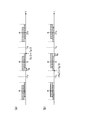
- FIG. 8A is a view for explaining the pass band of the filter of the extraction unit 57 of FIG. 6, and is a schematic view representing the pass band of the filter of the extraction unit 57 in the time domain.
- the effective symbol period is Tu
- the guard interval period is Tg
- the upsampling up rate is 2.
- the extraction unit 57 can extract signal components exceeding (Tu / Tg) / 2, interference components can be removed. From this, the left end of the pass band of the filter in the time domain is set so as to extract a signal component exceeding (Tu / Tg) / 2. However, the right end of the passband is deteriorated when the aliasing component is included, so it is preferable to set so that the aliasing component does not enter the filter passband.
- the filter coefficient in the frequency domain of the filter of the extraction unit 57 may be determined based on the contents described above.
- the downsampling unit 58 downsamples the interference vector E1 ′ 2 n supplied from the extraction unit 57 by half, and supplies the interference vector E1 ′ n obtained as a result of the downsampling to the phase rotation unit 59.
- FIG. 7 (j) schematically shows the interference vector E1 ' n in the frequency domain output from the down-sampling unit 58 as a signal in the time domain. As shown in FIG. 7 (j), when the interference vector E1 ' n in the frequency domain is represented by a signal in the time domain, it is represented by a repetitive signal having a period width Tu of an effective symbol period.
- the phase rotation unit 59 performs phase rotation for each carrier so as to shift the interference vector E1 ′ n supplied from the down-sampling unit 58 in time domain by ⁇ Tg time, and the interference vector E1 ′ rot n obtained as a result of phase rotation.
- FIG. 7 (k) schematically shows the interference vector E1 ' rot n in the frequency domain output from the phase rotation unit 59 by converting it into a signal in the time domain. From (a) of FIG. 7 and (k) of FIG.
- the time position of the interference component of the delayed wave intersymbol contained in the interference vector E1 ′ rot n is the time position of the interference component of the delayed wave intersymbol contained in the demodulation vector Y n. It turns out that they match.
- the process of rotating the phase of each carrier so as to shift the interference vector E1 ' n in the time domain by -Tg in the time domain is the frequency domain when the repetition cycle of the signal is Tu, that is, when the discrete frequency interval is 1 / Tu.
- the carrier number in f is f (f is an integer greater than 0 and less than N FFT and N FFT is the number of samples of discrete Fourier transform in OFDM demodulator 13)
- interference vector E1 ' n is 2 ⁇ ⁇ for each carrier in the frequency domain.
- This is processing to rotate the phase by ( ⁇ Tg / Tu) ⁇ f.
- the phase rotation is performed for each carrier so that other vectors are shifted by ⁇ Tg in the time domain.
- the phase rotation unit 53 performs phase rotation for each carrier so as to shift the equalization vector X ′ n corresponding to the n-th symbol supplied from the equalization unit 14 in time domain by Tg, and is obtained as a result of phase rotation.
- the equalized vector X ' rot n is supplied to the up-sampling unit 54.
- FIG. 7I schematically shows the frequency domain equalized vector X ′ rot n output from the phase rotation unit 53 by converting it into a time domain signal.
- the process of rotating the phase of each carrier to shift the equalization vector X ′ n in the time domain by Tg in the time domain is the frequency domain when the repetition cycle of the signal is Tu, that is, when the discrete frequency interval is 1 / Tu.
- the equalization vector X ′ n in the frequency domain is 2 ⁇ for each carrier. This is a process of phase rotation by ⁇ (Tg / Tu) ⁇ f. The same applies to the case where the phase rotation is performed for each carrier so as to shift other vectors by Tg time in the time domain.
- Upsampling unit 54 supplies the equalization vectors X supplied from the phase rotation unit 53 'to rot n upsampled doubled, the equalization vectors X obtained as a result of upsampling' the ROT2 n to the multiplication unit 60 .
- FIG. 7 (m) schematically shows the frequency domain equalization vector X ' rot2 n output from the up-sampling unit 54 converted into a time domain signal. Since the equalization vector X ' rot2 n is created by upsampling the equalization vector X' rot n having a discrete frequency interval of 1 / T by 2 times, the discrete frequency of the equalization vector X ' rot2 n The interval of is 1 / (2 ⁇ Tu). As shown in FIG. 7 (m), when the equalization vector X ' rot2 n in the frequency domain is represented by a signal in the time domain, it is represented by a repetitive signal having a period twice the time width Tu of the effective symbol period.
- the amplifier sampling unit 55 up-samples the channel response vector H ′ n corresponding to the n-th symbol supplied from the equalization unit 14 by 2 times, and the channel response vector H ′ 2 obtained as a result of the up-sampling. n is output to the multiplication unit 60 (see FIG. 2 (f)). This process is shared with the calculation of the delayed wave intersymbol interference component, and is not performed separately.
- the multiplication unit 60 multiplies, for each carrier, the equalization vector X ′ rot2 n supplied from the up-sampling unit 54 and the transmission path response vector H ′ 2 n supplied from the up-sampling unit 55, and the multiplication result is obtained.
- the demodulation vector Y2 ′ 2 n is supplied to the extraction unit 61.
- FIG. 7 (n) schematically shows the demodulation vector Y2 ′ 2 n in the frequency domain output from the multiplier 60 by converting it into a signal in the time domain, and the upper part shows the signal component related to the main wave, The lower part is a signal component related to the delay wave.
- the signal in the time domain shown in FIG. 7 (n) is a convolution of the signal shown in FIG. 7 (m) and the signal shown in FIG. 7 (f) in the time domain.
- the delay time td of the delay wave with respect to the main wave is effective by upsampling the equalization vector X ' rot n and the transmission path response vector H' n by 2 and doubling.
- the left and right repeated components separated by 2 ⁇ Tu do not interfere with each other.
- delayed wave inter-carrier interference components lacking in the demodulation vector Y n can be independently observed by using the demodulation vector Y 2 ′ 2 n .
- the extraction unit 61 is formed of, for example, an FIR filter, and has the same pass characteristic of the pass band as the extraction unit 57.
- the extraction unit 61 performs filter processing on the demodulation vector Y2 ′ 2 n supplied from the multiplication unit 60 to extract a delayed wave inter-carrier interference component related to the demodulation vector Y n from the demodulation vector Y2 ′ 2 n.
- An interference vector E 2 ′ 2 n representing the extracted delayed wave inter-carrier interference component is generated, and the generated interference vector E 2 ′ 2 n is supplied to the down-sampling unit 62.
- the delayed inter-carrier interference component extracted by the extracting unit 61 is td from the end of the delayed wave delayed by td with respect to the main wave in the nth symbol among the signal components included in the demodulation vector Y2 ′ 2 n. It is a signal component of (td ⁇ Tg) period from the time position before time, and is a signal component related to a delayed wave inter-carrier interference component lacking in the demodulation vector Y ′ n . Extraction of this signal component is made possible by applying phase rotation to the equalization vector X ′ in consideration of the guard interval period.
- FIG. 7 (o) is a schematic diagram showing the pass band of the filter of the extraction unit 61 in the time domain.
- FIG. 7 (p) schematically shows the interference vector E2 ′ 2 n in the frequency domain output from the extraction unit 61 by converting it into a signal in the time domain.
- the downsampling unit 62 downsamples the interference vector E 2 ′ 2 n supplied from the extraction unit 61 by half, and supplies the interference vector E 2 ′ n obtained as a result of the downsampling to the phase rotation unit 63.
- FIG. 7 (q) schematically shows the interference vector E2 ' n in the frequency domain output from the down-sampling unit 62 as a signal in the time domain. As shown in FIG. 7Q, when the interference vector E2 ' n in the frequency domain is represented by a signal in the time domain, it is represented by a repetitive signal having a period width Tu of the effective symbol period.
- the phase rotation unit 63 rotates the phase of each carrier so as to shift the interference vector E2 ' n supplied from the down-sampling unit 62 by -Tg in the time domain, and the interference vector E2' rot n obtained as a result of the phase rotation.
- FIG. 7 (r) schematically shows the interference vector E 2 ′ rot n in the frequency domain output from the phase rotation unit 63 as a signal in the time domain. From FIG. 7 (a) and FIG. 7 (r), the time position of the delayed wave inter-carrier interference component included in the interference vector E2 ' rot n is the time position of the delayed wave inter-carrier interference component included in the demodulation vector Y n It turns out that they match.
- Subtraction unit 64 subtracts the rot n interference vectors E1 supplied from the phase rotation unit 59 'interference vectors E2 from rot n supplied from the phase rotation unit 63', the interference vectors E1 resulting from the subtraction 'rot n -E2 ' rot n is supplied to the subtraction unit 65.
- the subtraction unit 65 subtracts the interference vector E1 ' rot n- E2' rot n supplied from the subtraction unit 64 from the demodulation vector Y n corresponding to the n-th symbol supplied from the OFDM demodulation unit 13, and the subtraction result
- FIG. 7 (s) schematically shows the demodulation vector Y ′ n in the frequency domain output from the subtraction unit 77 by converting it into a signal in the time domain.
- each interference component related to intersymbol interference and intercarrier interference due to delayed waves can be removed from the demodulation vector Y.
- transmission path equalization is performed again. For this reason, it is possible to use the transmission path response vector at the same time as the demodulation vector Y for the interference removal processing for the demodulation vector Y, and it is not affected by the time fluctuation of the transmission path. Is strong.
- the above reception apparatus 1 generates inter-symbol interference and inter-carrier interference even when the cutout position of the Fourier transform window for the OFDM transmission signal r (t) is not appropriately set, such inter-symbol interference and It is also possible to remove interference components relating to each of the inter-carrier interference.
- correction can be performed by performing phase rotation for each carrier based on the change value.
- the receiving apparatus of the present embodiment includes the interference removing unit 15a in which the internal configuration of the interference removing unit 15 of the first embodiment is changed, and the other components are substantially the same as the receiving apparatus 1. Therefore, only the interference removing unit 15a will be described.
- the same reference numerals are given to constituent elements substantially the same as the constituent elements of the first embodiment, and the description thereof is omitted since the description can be applied.
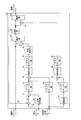
- FIG. 9 is a block diagram of the interference removal unit 15a of this embodiment
- FIGS. 10 (a) to 10 (n) are diagrams for explaining the processing contents of the interference removal unit 15a of FIG.
- the interference removal unit 15a includes a delay unit 51, a phase rotation unit 53, a subtraction unit 71, an upsampling unit 72, an upsampling unit 55, a multiplication unit 73, an extraction unit 74, and a downsampling unit 75.
- a phase rotation unit 76 and a subtraction unit 77 are provided.
- the interference removing unit 15 processes the delayed wave inter-symbol interference component and the delayed wave inter-carrier interference component separately.
- the interference removing unit 15a integrally processes the delayed wave inter-symbol interference component and the delayed wave inter-carrier interference component to reduce the circuit size and the amount of calculation.
- the demodulation vector Y output from the OFDM demodulation unit 13 is supplied to the subtraction unit 77 in the interference removal unit 15a.
- the equalization vector X 'output from the equalization unit 14 is supplied to the delay unit 51 and the phase rotation unit 53 in the interference removal unit 15a, and the channel response vector H' output from the equalization unit 14 is an interference removal unit It is supplied to the up sample unit 55 in 15 a.
- FIG. 10 (a) schematically shows, in the n-th symbol, the demodulation vector Y n in the frequency domain output by the OFDM demodulator 13 into a signal in the time domain, and (n-1) The signal components derived from the OFDM transmission signal s (n-1) (t) of the second symbol are indicated by hatching a left hatched pattern.
- FIG. 10B schematically shows, in the n-th symbol, the equalization vector X ′ n in the frequency domain output from the equalization unit 14 as a signal in the time domain.
- FIG. 10C schematically shows, in the n-th symbol, the channel response vector H ′ n in the frequency domain output from the equalizing unit 14 as a signal in the time domain.
- the equalization vector X ′ n, and the channel response vector H ′ n are represented by signals in the time domain, FIGS. 10 (a), 10 (b) and 10 (c) As shown in FIG. 2, the signal is represented by a repetitive signal having a period of time duration Tu of the effective symbol period.
- the demodulation vector Y n corresponding to the n-th symbol, the equalization vector X ′ n and the channel response vector H ′ n are supplied to the interference removing unit 15 a, the components of the interference removing unit 15 a
- the processing content will be described as an example.
- the delay unit 51 delays the equalization vector X ′ supplied from the equalization unit 14 by a time corresponding to a processing period of one symbol, and outputs the delayed signal.
- the delay unit The equalization vector X ′ (n ⁇ 1) corresponding to the (n ⁇ 1) th symbol is supplied to the subtraction unit 71 from the 51st to the 51st subtraction units.
- 10D schematically shows the equalization vector X ′ (n ⁇ 1) in the frequency domain output from the delay unit 51 as a signal in the time domain.
- the equalization vector X ' is obtained.
- the signal component relating to (n-1) is represented by a hatched pattern.
- the phase rotation unit 53 performs phase rotation for each carrier so as to shift the equalization vector X ′ n corresponding to the n-th symbol supplied from the equalization unit 14 in time domain by Tg, and is obtained as a result of phase rotation.
- the equalized vector X ′ rot n is supplied to the subtraction unit 71.
- FIG. 10E schematically shows the frequency domain equalization vector X ′ rot n output from the phase rotation unit 53 by converting it into a time domain signal.
- the subtraction unit 71 subtracts the equalization vector X ′ rot n supplied from the phase rotation unit 53 from the equalization vector X ′ (n ⁇ 1) supplied from the delay unit 51, and obtains the difference obtained as a result of the subtraction, etc.
- FIG. 10 (f) schematically shows the frequency-domain differential equalization vector XA ' (n-1), n output from the subtractor 71 by converting it into a signal in the time domain.
- a signal component corresponding to the equalization vector X ' (n-1) (a portion indicated by a hatched left hatching) and a signal component corresponding to the equalization vector X' rot n (pattern Although it is schematically represented by overlapping the portion shown without applying), in actuality, the signal component represented by the differential equalization vector XA ′ (n ⁇ 1), n subtracts the signal component of the lower stage from the signal component of the upper stage Signal component.
- the upsampling unit 72 upsamples the differential equalization vector XA ′ (n ⁇ 1), n supplied from the subtraction unit 71 by 2 times, and obtains the differential equalization vector XA ′ 2 (n -1) and n are supplied to the multiplication unit 73.
- FIG. 10G schematically shows the frequency-domain differential equalization vector XA ′ 2 (n ⁇ 1), n output from the up-sampling unit 72 converted into a time-domain signal.
- the up-sampling unit 55 up-samples the channel response vector H ′ n corresponding to the n-th symbol supplied from the equalization unit 14 by 2 times, and the channel response vector H ′ 2 obtained as a result of the up-sampling. n is supplied to the multiplication unit 73.
- FIG. 10H schematically shows the channel response vector H ′ 2 n in the frequency domain output from the up-sampling unit 55 by converting it into a signal in the time domain.
- the multiplication unit 73 multiplies the difference equalization vector XA ′ 2 (n ⁇ 1), n supplied from the up-sampling unit 72 by the channel response vector H ′ 2 n supplied from the up-sampling unit 55 to perform multiplication.
- the differential demodulation vector YA ′ 2 (n ⁇ 1), n obtained as a result of the above is supplied to the extraction unit 74.
- FIG. 10 (i) schematically shows the differential demodulation vector YA ′ 2 (n ⁇ 1), n in the frequency domain output from the multiplier 73 as a signal in the time domain and the upper part shows the main The lower part is a signal component related to a wave, and the lower part is a signal component related to a delay wave.
- the extraction unit 74 is formed of, for example, an FIR filter, and has the same pass characteristics as the extraction unit 57 in the pass band. Extraction unit 74, the multiplication unit 73 the difference demodulation vectors YA supplied from '2 (n-1), by performing filter processing to n, the difference demodulation vectors YA' 2 (n-1), from n, the demodulation vectors The delayed wave intersymbol interference component related to Y n and the delayed wave intercarrier interference component related to it are extracted, and an interference vector EA ′ 2 n representing the extracted delayed wave intersymbol interference component and the delayed wave intercarrier interference component is generated , And supplies the generated interference vector EA ′ 2 n to the down-sampling unit 75.
- FIG. 10 (j) is a schematic diagram showing the pass band of the filter of the extraction unit 74 in the time domain.
- FIG. 10 (k) schematically shows the interference vector EA ′ 2 n in the frequency domain output from the extraction unit 74 by converting it into a signal in the time domain.
- the downsampling unit 75 downsamples the interference vector EA ′ 2 n supplied from the extraction unit 74 by 1 ⁇ 2, and supplies the interference vector EA ′ n obtained as a result of the downsampling to the phase rotation unit 76.
- FIG. 10 (l) schematically shows the interference vector EA ' n output from the down-sampling unit 75 by converting it into a time domain signal.
- the phase rotation unit 76 rotates the phase of each carrier so as to shift the interference vector EA ′ n supplied from the down-sampling unit 75 by ⁇ Tg in the time domain, and the interference vector EA ′ rot n obtained as a result of the phase rotation.
- FIG. 10 (m) schematically represents the interference vector EA ' rot n in the frequency domain output from the phase rotation unit 76 into a signal in the time domain. From (a) of FIG. 10 and (m) of FIG.
- the subtraction unit 77 subtracts the interference vector EA ′ rot n supplied from the phase rotation unit 76 from the demodulation vector Y n corresponding to the n-th symbol supplied from the OFDM demodulation unit 13 and demodulates the result obtained by the subtraction.
- FIG. 10 (n) schematically represents the demodulation vector Y ′ n in the frequency domain output by the subtraction unit 77 into a signal in the time domain.
- the delay unit 51, the subtraction unit 71, the upsampling unit 72, the upsampling unit 55, the multiplication unit 73, the extraction unit 74, the downsampling unit 75, the phase rotation unit 76, and the subtraction unit 77 To realize the function of removing
- the phase rotation unit 53, the subtraction unit 71, the upsampling unit 72, the upsampling unit 55, the multiplication unit 73, the extraction unit 74, the downsampling unit 75, the phase rotation unit 76, and the subtraction unit 77 Implement a function to remove interference.
- the receiving apparatus of each of the above embodiments is intended to remove only intersymbol interference and intercarrier interference due to delayed waves.
- the receiver 1b according to the present embodiment also targets intersymbol interference and intercarrier interference due to preceding waves.
- the same reference numerals are given to constituent elements substantially the same as the constituent elements of each of the above-described embodiments, and the description thereof is omitted since the description can be applied.
- one preceding wave is larger than the guard interval period Tg with respect to the main wave, as to an outline of intersymbol interference and intercarrier interference due to preceding waves.
- the case where the signal arrives at the receiving device ahead of time will be described as an example with reference to FIGS. 11 (a) to 11 (g).
- 11 (a) to 11 (g) are diagrams for explaining an outline of inter-symbol interference and inter-carrier interference due to preceding waves, and the horizontal axis in each of FIGS. 11 (a) to 11 (g). Indicates time.
- FIG. 11 (a) schematically shows the OFDM transmission signal s (t) for a plurality of symbols transmitted continuously, and the transmitting station transmits the OFDM transmission signal continuously for a plurality of symbols.
- the transmitting station transmits the OFDM transmission signal continuously for a plurality of symbols.
- the OFDM transmission signal s n (t) of the focused n-th symbol is the OFDM transmission signal s (n-1) (t) of the (n-1) -th symbol adjacent to
- the pattern of the left diagonal line on the OFDM transmission signal s (n-1) (t) of the (n-1) th symbol Is represented by the rightward hatching pattern on the OFDM transmission signal s (n + 1) (t) of the (n + 1) th symbol.
- FIG. 11 (b) schematically shows a channel response signal h (t) representing a channel response.
- the time difference td in which two incoming waves have arrived is larger than the guard interval period Tg is targeted.
- FIG. 11C schematically shows an OFDM transmission signal r (t) received by the receiving apparatus.
- the arrival wave (principal wave) arriving second is shown on the upper stage, and the arrival wave (preceding wave) arriving earlier than the main wave td time is superimposed on the lower stage, but in reality they are additively superimposed Are received in the It is to be noted that the same is applied to FIGS. 11 (e) and 11 (g).
- the signal components derived from the OFDM transmission signal s (n-1) (t) are hatched with left hatching, and the signal components derived from the OFDM transmission signal s (n + 1) (t) In the right hatched pattern.
- the pattern is similarly applied and represented also about FIG.11 (e) and FIG.11 (f).
- the receiving apparatus that receives the OFDM transmission signal extracts and demodulates the OFDM transmission signal for the time width Tu of the effective symbol period from the received OFDM transmission signal r (t) for each symbol. In the n-th symbol, the receiving apparatus performs the OFDM transmission shown in FIG. 11 (e) for the time width Tu of the effective symbol period shown in FIG. 11 (c) to the OFDM transmission signal r (t) shown in FIG. Cut out the signal r n (t).
- FIG. 11F shows signal components derived from the OFDM transmission signal s (n + 1) (t) of the (n + 1) th symbol included in the OFDM transmission signal r n (t) shown in FIG. It represents.
- the signal component derived from the OFDM transmission signal s (n + 1) (t) of the (n + 1) th symbol is the interference component related to intersymbol interference due to the leading wave in the OFDM transmission signal r n (t) of the nth symbol It is.
- the interference component related to the intersymbol interference due to the preceding wave in the OFDM transmission signal r n (t) of the nth symbol is a guard of the preceding wave with respect to the OFDM transmission signal s (n + 1) (t) of the (n + 1) th symbol It is a signal component of (td ⁇ Tg) period from the beginning of the interval. Note that this signal component is equivalent to the signal component in the (td-Tg) period from the time position Tg time before the end of the preceding wave of the (n + 1) th symbol of the OFDM transmission signal s (n + 1) (t) That is, in the present embodiment, the removal of the interference component related to the inter-symbol interference due to the preceding wave is performed using the latter signal component.
- FIG. 11 (g) shows a signal component derived from the OFDM transmission signal s n (t) of the n-th symbol included in the OFDM transmission signal r n (t) shown in FIG. 11 (e).
- the time width of the signal component of the leading wave derived from the OFDM transmission signal s n (t) of the nth symbol included in the OFDM transmission signal r n (t) is the time width Tu of the effective symbol period It is understood that it is less than.
- the time width of the signal component of the preceding wave is less than the time width Tu of the effective symbol period, orthogonality among a plurality of carriers forming the OFDM transmission signal r n (t) can not be maintained, and Inter-carrier interference will occur when demodulating each one.
- the interference component related to inter-carrier interference due to the preceding wave in the OFDM transmission signal r n (t) of the nth symbol is from the beginning of the effective symbol period of the preceding wave related to the OFDM transmission signal s n (t) of the nth symbol ( It is a signal component of the (td ⁇ Tg) period.
- FIG. 12 is a block diagram of 1b of the present embodiment
- FIG. 13 (a) to FIG. 13 (g) are diagrams for explaining the processing contents of the reception device 1b of FIG.
- the receiver 1 b includes an antenna 11, a tuner 12, an OFDM demodulator 13, an equalizer 14, an interference remover 15 b, an equalizer 16, and a demodulator 17.
- the processing content of each part excluding the interference removal unit 15b is substantially the same as the processing content described in the first embodiment, and the detailed description of the interference removal unit 15b will be from FIG. 14 and FIG. This will be described later using 15 (o).
- the processing contents from the antenna 11 to the equalization unit 14 are described.
- the antenna 11 receives an OFDM transmission signal emitted from a transmitting station (not shown) and supplies the received OFDM transmission signal to the tuner 12.
- the tuner 12 selects an OFDM transmission signal r (t) of a desired channel from the OFDM transmission signal supplied from the antenna 11, and outputs the selected OFDM transmission signal r (t) to the OFDM demodulation unit 13.
- FIG. 13 (a) schematically shows the OFDM transmission signal s (t) emitted from the transmitting station, and X (n-1) , Xn and X (n + ) in FIG. 13 (a).
- 1) represents a modulation vector in which a plurality of carriers are modulated on the transmission side in the (n-1) th symbol, the nth symbol and the (n + 1) th symbol, respectively.
- the OFDM transmission signal s (n-1) (t) of the (n-1) th symbol is hatched with a left diagonal pattern
- the OFDM transmission signal s (n + 1) (t) of the (n + 1) th symbol is It is shown with a pattern of right diagonal lines.
- FIG. 13 (b) schematically shows the transmission path response signal h (t).
- the channel response signal h (t) an example of which is shown in FIG. 13B
- three incoming waves arrive at the receiving apparatus 1b, and the second arriving signal with the highest reception level is the main wave.
- the first arrival wave (preceding wave) arrives tp time ahead of the main wave
- the third arrival wave (delayed wave) arrives td time later than the main wave It shows how you are doing.
- Tg the guard interval period
- FIG. 13C schematically shows the OFDM transmission signal r (t) received and selected by the receiving apparatus 1b.
- the first arriving wave preceding wave
- the second arriving wave main wave
- the third arriving wave delay wave
- they are shown superimposed on the lower part, they are actually received in an additively superimposed state.
- FIG. 13 (e) they are superimposed and displayed in the same manner.
- the signal components derived from the OFDM transmission signal s (n-1) (t) are hatched with left hatching, and the signal components derived from the OFDM transmission signal s (n + 1) (t) In the right hatched pattern.
- the OFDM demodulator 13 performs OFDM transmission corresponding to the time width Tu of the effective symbol period shown in FIG. 13C from the OFDM transmission signal r (t) shown in FIG. 13C supplied from the tuner 12 for each symbol. A signal is cut out and discrete Fourier transform is applied to the cut out OFDM transmission signal. Then, the OFDM demodulation unit 13 supplies the demodulation vector Y obtained as a result of the discrete Fourier transform to the equalization unit 14 and the interference removal unit 15b.
- FIG. 13 (e) schematically shows the demodulation vector Y in the frequency domain output from the OFDM demodulator 13 by converting it into a signal in the time domain. However, symbols Y (n-1) , Y n and Y (n + 1) in FIG.
- the equalization unit 14 estimates a channel response vector H ′ from the demodulation vector Y supplied from the OFDM demodulation unit 13 and equalizes the demodulation vector Y based on the estimated channel response vector H ′ to equalize the equalization vector X 'Is calculated, and the transmission path response vector H' and the equalization vector X 'are supplied to the interference removing unit 15b.
- FIG. 13 (f) schematically shows the channel response vector H ′ in the frequency domain output from the equalizer 14 by converting it into a signal in the time domain
- FIG. 13 (g) shows equalization The equalization vector X ′ in the frequency domain output from the unit 14 is converted into a signal in the time domain and schematically represented.
- H ' (n-1) , H' n and H ' (n + 1) in FIG. 13 (f) are the (n-1) th symbol, the nth symbol and the (n + 1) th, respectively.
- X ' (n-1) , X' n and X ' (n + 1) in FIG. 13 (g) are the (n-1) th symbol, the nth symbol and the (n + 1) th, respectively.
- the equalization vector X ′ output from the equalization unit 14 is a reproduction of the modulation vector X modulated on the transmission side by the transmission path equalization processing. However, under an environment where the arrival time difference between the leading wave and the delay wave exceeds the guard interval period Tg, the equalization vector X ′ output from the equalization unit 14 is a symbol based on the leading wave and the delay wave with respect to the modulation vector X It includes interference components relating to inter interference and inter carrier interference.
- FIG. 14 is a block diagram of the interference removing unit 15b of FIG. 12, and FIGS. 15 (a) to 15 (o) are diagrams for explaining the processing contents of the interference removing unit 15b of FIG.
- the interference removal unit 15b has a configuration in which a delay unit 81, an upsampling unit 82, a multiplication unit 83, an extraction unit 84, a downsampling unit 85, a delay unit 86, and an addition unit 87 are added to the interference removal unit 15a.
- the demodulation vector Y output from the OFDM demodulation unit 13 is supplied to the subtraction unit 77 in the interference removal unit 15b.
- the equalization vector X ′ output from the equalization unit 14 is supplied to the delay unit 51 and the phase rotation unit 53 in the interference removal unit 15 b, and the channel response vector H ′ output from the equalization unit 14 is an interference removal unit
- the signal is supplied to the up-sampling unit 55 and the delay unit 81 in 15 b.
- FIG. 15 (a) schematically shows, in the n-th symbol, the demodulation vector Y n in the frequency domain output by the OFDM demodulator 13 into a signal in the time domain and (n-1)
- the signal component derived from the OFDM transmission signal s (n-1) (t) of the th symbol is indicated by hatching the left hatched pattern, and the OFDM transmission signal s (n + 1) (t) of the (n + 1) th symbol is represented The signal components derived from are hatched to the right.
- FIG. 15 (b) schematically shows, in the n-th symbol, the equalization vector X n 'in the frequency domain output from the equalization unit 14 as a signal in the time domain.
- FIG. 15C schematically shows the channel response vector H n ′ in the frequency domain output from the equalizer 14 in the n-th symbol, converted to a signal in the time domain.
- the configuration and operation of the interference removing unit 15b will be described in two parts: removal of intersymbol interference and intercarrier interference due to delayed waves and removal of intersymbol interference and intercarrier interference due to preceding waves.
- the processing content of each part in the interference removal unit 15b when the demodulation vector Y n , the equalization vector X ′ n and the channel response vector H ′ n corresponding to the n-th symbol are supplied to the interference removal unit 15b An example will be described.
- the delay unit 51, the phase rotation unit 53, the subtraction unit 71, the up sampling unit 72, the up sampling unit 55, the multiplication unit 73, the extraction unit 74, the down sampling unit 75, the phase rotation unit 76, and the subtraction unit 77 are each described above.
- FIG. 15 (d) schematically shows the demodulation vector YB ' n in the frequency domain output from the subtractor 77 by converting it into a signal in the time domain, and represents the OFDM transmission signal s of the (n + 1) th symbol. Signal components derived from (n + 1) (t) are indicated by hatching to the right.
- the pass band of the extraction unit 74 is in addition to the setting method of the pass band of the filter of the extraction unit 57 described in the first embodiment, It is preferable to set so as not to overlap with the pass band of the filter of the extraction unit 84 on the preceding wave side.
- the delay unit 51, the phase rotation unit 53, the subtraction unit 71, and the up-sampling unit 72 each perform the processing of the above-described processing content, and the up-sampling unit 72 performs difference equalization vector XA ' 2 (n-1), n is supplied to the multiplication unit 83. Note that these processes are shared with the removal of intersymbol interference and intercarrier interference due to delayed waves, and are not performed separately.
- FIG. 15 (e) schematically shows the equalization vector X ′ (n ⁇ 1) in the frequency domain output from the delay unit 51 as a signal in the time domain.
- FIG. 15F schematically represents the equalization vector X ′ rot n in the frequency domain output from the phase rotation unit 53 into a signal in the time domain.
- FIG. 15 (g) schematically shows the frequency-domain differential equalization vector XA ' (n-1), n output from the subtractor 71 by converting it into a signal in the time domain.
- FIG. 15H schematically shows the frequency-domain differential equalization vector XA ′ 2 (n ⁇ 1), n output from the up-sampling unit 72 by converting it into a time-domain signal.
- 15 (e), 15 (g), 15 (h), 15 (j), 15 (l) and 15 (m ) relate to the equalization vector X ' (n-1). The signal components are shown with a hatched pattern.
- the delay unit 81 delays the channel response vector H ′ supplied from the equalization unit 14 by the time corresponding to the processing period of one symbol and outputs the delayed signal.
- the delay unit A channel response vector H ′ (n ⁇ 1) corresponding to the (n ⁇ 1) th symbol is supplied from the 81st to the upsample 82.
- the amplifier sampling unit 82 upsamples the transmission path response vector H ′ (n ⁇ 1) supplied from the delay unit 81 by 2 times, and acquires the transmission path response vector H ′ 2 (n ⁇ 1) obtained as a result of the upsampling. ) Is supplied to the multiplication unit 83.
- FIG. 15I schematically shows the channel response vector H ′ 2 (n ⁇ 1) in the frequency domain outputted by the up-sampling unit 82 as a signal in the time domain. Since the transmission path response vector H ′ 2 (n ⁇ 1) is created by up-sampling the transmission path response vector H ′ (n ⁇ 1) having a discrete frequency interval of 1 / Tu, transmission is performed.
- the interval of discrete frequencies of the road response vector H ′ 2 (n ⁇ 1) is 1 / (2 ⁇ Tu).
- the channel response vector H ′ 2 (n ⁇ 1) in the frequency domain is represented by a signal in the time domain, it is a repetitive signal having a period twice the time width Tu of the effective symbol period. Is represented by
- the multiplying unit 83 calculates the differential equalization vector XA ′ 2 (n ⁇ 1), n supplied from the up-sampling unit 72 and the channel response vector H ′ 2 (n ⁇ 1) supplied from the up-sampling unit 82. Multiplication is performed for each carrier, and the differential demodulation vector YB2 ′ 2 (n ⁇ 1), n obtained as a result of the multiplication is supplied to the extraction unit 84.
- FIG. 15 (j) schematically shows the differential demodulation vector YB2 ′ 2 (n ⁇ 1), n in the frequency domain output from the multiplier 83 as a signal in the time domain, and the upper part shows the preceding.
- the middle part is the signal component related to the main wave, and the lower part is the signal component related to the delayed wave.
- the signal in the time domain shown in FIG. 15 (j) is a convolution of the signal shown in FIG. 15 (h) and the signal shown in FIG. 15 (i) in the time domain.
- the extraction unit 84 is formed of, for example, an FIR filter and has the pass characteristic of the pass band described below. Extraction unit 84, the multiplication unit 83 the difference demodulation vectors YB2 supplied from '2 (n-1), by performing filter processing to n, the difference demodulation vectors YB2' 2 (n-1), from n, the demodulation vectors Interference component related to inter-symbol interference due to the preceding wave related to Y (n-1) (hereinafter referred to as “inter-preceding wave inter-symbol interference component”) and interference component related to inter-carrier interference due to the preceding wave related thereto , Referred to as “preceding wave inter-carrier interference component”, and generated and generated an interference vector EB ′ 2 (n ⁇ 1) representing the extracted preceding wave inter-symbol interference component and the extracted preceding wave inter-carrier interference component.
- inter-preceding wave inter-symbol interference component Interference component related to inter-sym
- FIG. 15 (k) is a schematic diagram showing the pass band of the filter of the extraction unit 84 in the time domain
- FIG. 15 (l) is an interference vector EB ' 2 (n- of the frequency domain output by the extraction unit 85). 1) is schematically represented by converting it into a time domain signal.
- FIG. 8B is a view for explaining the pass band of the filter of the extraction unit 84 of FIG. 14, and is a schematic view representing the pass band of the filter of the extraction unit 84 in the time domain.
- the effective symbol period is Tu
- the guard interval period is Tg
- the upsampling up rate is 2.
- the extraction unit 84 can extract signal components exceeding-(Tu / Tg) / 2, interference components can be removed. From this, the right end of the pass band of the filter in the time domain is set so as to extract signal components exceeding-(Tu / Tg) / 2. However, the left end of the pass band is deteriorated when the aliasing component is included, so it is preferable to set so that the aliasing component does not enter the filter pass band. Further, in the case where both the leading wave and the delayed wave are targeted, it is preferable to set the pass band of the extraction unit 84 so as not to overlap with the pass band of the filter of the extraction unit 74 on the delayed wave side.
- the filter coefficient in the frequency domain of the filter of the extraction unit 84 may be determined based on the above-described content.
- the downsampling unit 85 downsamples the interference vector EB ′ 2 (n ⁇ 1) supplied from the extraction unit 84 by half, and obtains the interference vector EB ′ (n ⁇ 1) obtained as a result of the downsampling.
- the signal is supplied to the adding unit 87.
- FIG. 15 (m) schematically shows the interference vector EB ' (n-1) in the frequency domain output from the down-sampling unit 86 by converting it into a signal in the time domain. As shown in FIG. 15 (m), when the interference vector EB ' (n-1) in the frequency domain is represented by a signal in the time domain, it is represented by a repetitive signal having a period width Tu of the effective symbol period.
- the delay unit 86 delays and outputs the demodulation vector YB ′ supplied from the subtraction unit 77 by a time corresponding to a processing period of one symbol.
- the demodulation vector Y n the equalization vector X ′ n and the channel response vector H ′ n corresponding to the n-th symbol are supplied to the interference removal unit 15 b and the interference removal unit 15 b performs processing (n -1)
- the demodulation vector Y (n-1) , the equalization vector X ' (n-1), and the channel response vector H' (n-1) corresponding to the first symbol are supplied to the interference removing unit 15b and interference is generated.
- FIG. 15 (n) schematically represents the demodulation vector YB ′ (n ⁇ 1) in the frequency domain output from the delay unit 86 into a signal in the time domain. From FIG. 15 (m) and FIG.
- the time positions of the interference component between the preceding wave intersymbol and the interference component between the preceding wave and the interference component between the preceding wave included in the interference vector EB ' (n-1) are demodulated vector YB' (n- It can be seen that they coincide with the time positions of the preceding wave inter-symbol interference component and the preceding wave inter-carrier interference component included in 1) .
- the adding unit 87 adds the demodulation vector YB ′ (n ⁇ 1) supplied from the delay unit 86 and the interference vector EB ′ (n ⁇ 1) supplied from the down sampling unit 85, and the addition result is demodulated vector Y
- the phase rotation unit 53, the subtraction unit 71, the upsampling unit 72, the delay unit 81, the upsampling unit 82, the multiplication unit 83, the extraction unit 84, the downsampling unit 85, the delay unit 86, and the addition unit 87 To realize the function of removing intersymbol interference by However, when only inter-symbol interference due to the preceding wave is removed, the phase rotation unit 53, the subtraction unit 71, the upsampling unit 72, the delay unit 81, the upsampling unit 82, the multiplication unit 83, the extraction unit 84, the downsampling A unit 85, a delay unit 86, and an addition unit 87 may be provided.
- the subtraction unit 71 may be deleted so as to be equivalent to the subtraction unit 71 and the addition unit 87, and the addition unit 87 may be replaced with a subtraction unit.
- the delay unit 51, the subtraction unit 71, the upsampling unit 72, the delay unit 81, the upsampling unit 82, the multiplication unit 83, the extraction unit 84, the downsampling unit 85, the delay unit 86, and the addition unit 87 Implement a function to remove interference. However, when only inter-carrier interference due to the preceding wave is removed, the up-sampling unit 72, the up-sampling unit 82, the multiplying unit 83, the extracting unit 84, the down-sampling unit 85, the delay unit 86, and the adding unit 87 are provided. Just do it.
- the interference component related to the intersymbol interference and the intercarrier interference due to the preceding wave can be removed from the demodulation vector Y. Can be effectively suppressed. Also, even if the number of preceding waves arriving at the receiving apparatus is two or more, it is possible to remove from the demodulation vector Y interference components relating to intersymbol interference and intercarrier interference due to preceding waves.
- the interference removing unit 15c according to the present embodiment is a modification of the interference removing unit 15b according to the third embodiment in the configuration of the block for removing the intersymbol interference and the intercarrier interference due to the preceding wave.
- the same reference numerals are given to constituent elements substantially the same as the constituent elements of each of the above-described embodiments, and the description thereof is omitted since the description can be applied.
- FIG. 16 is a block diagram of the interference removal unit 15c of this embodiment.
- the interference removing unit 15c extracts the processing block including the delaying unit 81, the upsampling unit 82, the multiplying unit 83, the extracting unit 84, the downsampling unit 85, and the adding unit 87 with respect to the interference removing unit 15b in FIG. It has a configuration in which it is replaced by a processing block consisting of 91, a down-sampling unit 92 and an adding unit 93.
- the delay unit 51, the phase rotation unit 53, the subtraction unit 71, the up-sampling unit 72, the up-sampling unit 55, and the multiplication unit 73 perform the processing described above, and the multiplication unit 73 processes the differential demodulation vector YA ' 2. (n ⁇ 1), n are supplied to the extraction unit 91.
- the extraction unit 91 is formed of, for example, an FIR filter, and has the same pass characteristics as the extraction unit 84 in the pass band. Extraction unit 91, the multiplication unit 73 the difference demodulation vectors YA supplied from '2 (n-1), by performing filter processing to n, the difference demodulation vectors YA' 2 (n-1), from n, the demodulation vectors An interference vector EC ′ representing the preceding wave inter-symbol interference component related to Y (n ⁇ 1) and the preceding wave inter-carrier interference component related to it, and the extracted preceding wave inter-symbol interference component and the preceding wave inter-carrier interference component 2 (n ⁇ 1) is generated, and the generated interference vector EC ′ 2 (n ⁇ 1) is supplied to the down sample unit 92.
- the downsampling unit 92 downsamples the interference vector EC ′ 2 (n ⁇ 1) supplied from the extraction unit 91 by half, and obtains the interference vector EC ′ (n ⁇ 1) obtained as a result of the downsampling.
- the data is supplied to the adding unit 93.
- the delay unit 86 delays and outputs the demodulation vector YB ′ supplied from the subtraction unit 77 by a time corresponding to a processing period of one symbol.
- the demodulation vector Y n the equalization vector X ′ n and the channel response vector H ′ n corresponding to the n-th symbol are supplied to the interference removal unit 15 c and the interference removal unit 15 c performs processing (n -1)
- the demodulation vector Y (n-1) , the equalization vector X ' (n-1), and the channel response vector H' (n-1) corresponding to the first symbol are supplied to the interference removing unit 15c and interference is generated.
- the removal unit 15 c performing processing, the demodulation vector YB ′ (n ⁇ 1) supplied from the subtraction unit 77 to the delay unit 86 is supplied from the delay unit 86 to the addition unit 93.
- the addition unit 93 adds the demodulation vector YB ′ (n ⁇ 1) supplied from the delay unit 86 and the interference vector EC ′ (n ⁇ 1) supplied from the down sampling unit 92, and the addition result is demodulated vector Y
- the interference removal unit 15c removes intersymbol interference and intercarrier interference due to the preceding wave using a channel response vector one symbol after the demodulation vector. For this reason, when there is a frequency deviation between transmitting stations, or when the channel response fluctuates with time due to movement of the receiving apparatus, etc., the reception quality slightly decreases, but the delay unit 81, the upsampling unit 82, and multiplication Since the unit 83 is unnecessary, the circuit scale and the amount of calculation can be reduced.
- the interference removing unit 15d of the present embodiment is a modification of the method of removing inter-symbol interference due to delayed waves and inter-carrier interference due to preceding waves of the third interference removing unit 15 b.
- the same reference numerals are given to constituent elements substantially the same as the constituent elements of each of the above-described embodiments, and the description thereof is omitted since the description can be applied.
- FIG. 17 is a block diagram of the interference removal unit 15d of the present embodiment.
- the interference removal unit 15d has a configuration in which the delay unit 51 is replaced with a division unit 96 with respect to the interference removal unit 15b of FIG.
- the configuration and operation of the interference removing unit 15d will be described in two parts: removal of intersymbol interference and intercarrier interference due to delayed waves and removal of intersymbol interference and intercarrier interference due to preceding waves.
- the processing content of each part in the interference removal unit 15d when the demodulation vector Y n , the equalization vector X ′ n and the channel response vector H ′ n corresponding to the n-th symbol are supplied to the interference removal unit 15d An example will be described.
- the delay unit 86 delays and outputs the demodulation vector YD ′ supplied from the subtraction unit 77 by a time corresponding to a processing period of one symbol.
- the interference removal unit 15d is supplied with the demodulation vector Y n corresponding to the n-th symbol, the equalization vector X ' n , and the channel response vector H' n to the interference removal unit 15d, and the interference removal unit 15d processes
- the interference removal unit 15 d performs demodulation
- the demodulation vector YD ′ (n ⁇ 1) supplied from the subtraction unit 77 to the delay unit 86 is supplied from the delay unit 86 to the addition unit 87 and the division unit 96 when the interference removal unit 15 d performs the processing
- the division unit 96 divides the demodulation vector YD ' (n-1) supplied from the delay unit 86 by the channel response vector H' n corresponding to the n-th symbol supplied from the equalization unit 14, and the division result Are supplied to the subtractor 71 as an equalization vector XD ′ (n ⁇ 1) .
- the phase rotation unit 53 performs phase rotation for each carrier so as to shift the equalization vector X ′ n corresponding to the n-th symbol supplied from the equalization unit 14 in time domain by Tg, and is obtained as a result of phase rotation.
- the equalized vector X ′ rot n is supplied to the subtraction unit 71.
- the subtraction unit 71 subtracts the equalization vector X ′ rot n supplied from the phase rotation unit 53 from the equalization vector XD ′ (n ⁇ 1) supplied from the division unit 96, and obtains the difference obtained as a result of the subtraction, etc.
- the upsampling unit 72 is supplied with the quantization vector XD ′ (n ⁇ 1) ⁇ X ′ rot n .
- the upsampling unit 72, the upsampling unit 55, the multiplication unit 73, the extraction unit 74, the downsampling unit 75, the phase rotation unit 76, and the subtraction unit 77 execute processing of substantially the same processing content as the processing content described above.
- the subtraction unit 77 supplies the demodulation vector YD ′ n to the delay unit 86.
- Delay unit 86 (Removal of intersymbol interference and intercarrier interference due to preceding wave) Delay unit 86, division unit 96, phase rotation unit 53, subtraction unit 71, up-sampling unit 72, delay unit 81, up-sampling unit 82, multiplication unit 83, extraction unit 84, down-sampling unit 85, and addition unit 87 respectively
- the above-described processing content or processing of substantially the same processing content is performed, and the addition unit 87 supplies the demodulation vector Y ′ (n ⁇ 1) to the equalization unit 16.
- the processing of the delay unit 86, the division unit 96, the phase rotation unit 53, the subtraction unit 71, and the up-sampling unit 72 is shared with the cancellation of intersymbol interference and intercarrier interference due to delayed waves, Absent.
- the demodulation vector YD ' (n-1) from which intersymbol interference due to the delayed wave and intercarrier interference due to the delayed wave have been removed is divided by the channel response vector H n to obtain an equalization vector.
- XD ' (n-1) is generated and used to remove intersymbol interference due to delayed waves and intercarrier interference due to preceding waves. Therefore, as compared with the case where equalization vector X ′ (n ⁇ 1) is used as it is, the performance of removing inter-symbol interference due to delayed waves and inter-carrier interference due to preceding waves is improved.
- the dividing unit 96 is added, the delay unit 51 is deleted, so that the memory capacity for one symbol can be reduced.
- the interference removing unit 15e of the present embodiment is the interference removing unit 15d of the fifth embodiment to which a function of selecting a demodulation vector according to the reception quality is added.
- the same reference numerals are given to constituent elements substantially the same as the constituent elements of each of the above-described embodiments, and the description thereof is omitted since the description can be applied.
- FIG. 18 is a block diagram of the interference removal unit 15e of the present embodiment.
- the interference removing unit 15e is different from the interference removing unit 15d of FIG. 17 in the block including the subtracting unit 77, the delay unit 86, and the adding unit 87 as the subtracting unit 77, the selecting unit 101, the delay unit 86, the adding unit 87, and the selecting unit It has a configuration replaced with a block consisting of 102.
- the configuration and operation of the interference removing unit 15e will be described in two parts: removal of intersymbol interference and intercarrier interference due to delayed waves and removal of intersymbol interference and intercarrier interference due to preceding waves.
- the processing content of each part in the interference removal unit 15e when the demodulation vector Y n , the equalization vector X ′ n and the channel response vector H ′ n corresponding to the n-th symbol are supplied to the interference removal unit 15e An example will be described.
- the delay unit 86 delays and outputs the demodulation vector YD ′ supplied from the selection unit 101 by a time corresponding to a processing period of one symbol.
- the interference removal unit 15e is supplied with the demodulation vector Y n corresponding to the n-th symbol, the equalization vector X ′ n , and the channel response vector H ′ n to the interference removal unit 15e, and the interference removal unit 15e processes
- the interference removal unit 15 e performs the demodulation vector Y (n ⁇ 1) corresponding to the (n ⁇ 1) th symbol, the equalization vector X ′ (n ⁇ 1) , and the channel response vector H ′ (n ⁇
- the demodulation vector YE ' (n-1) supplied from the selection unit 101 to the delay unit 86 by the processing in the interference removal unit 15e being supplied with 1) is processed by the delay unit 86 to the addition unit 87, the selection unit 102, and the division. It is
- the division unit 96 divides the demodulation vector YE ′ (n ⁇ 1) supplied from the delay unit 86 by the channel response vector H ′ n corresponding to the nth symbol supplied from the equalization unit 14, and the division result Are supplied to the subtractor 71 as an equalization vector XE ′ (n ⁇ 1) .
- the phase rotation unit 53 performs phase rotation for each carrier so as to shift the equalization vector X ′ n corresponding to the n-th symbol supplied from the equalization unit 14 in time domain by Tg, and is obtained as a result of phase rotation.
- the equalized vector X ′ rot n is supplied to the subtraction unit 71.
- the subtraction unit 71 subtracts the equalization vector X ′ rot n supplied from the phase rotation unit 53 from the equalization vector XE ′ (n ⁇ 1) supplied from the division unit 96, and obtains the difference obtained as a result of the subtraction, etc.
- the upsampling unit 72 is supplied with the quantization vector XE ′ (n ⁇ 1) ⁇ X ′ rot n .
- the upsampling unit 72, the upsampling unit 55, the multiplication unit 73, the extraction unit 74, the downsampling unit 75, the phase rotation unit 76, and the subtraction unit 77 execute processing of substantially the same processing content as the processing content described above. Then, the subtraction unit 77 supplies the demodulation vector YE1 ′ n to the selection unit 101.
- the selection unit 101 compares the reception quality of the demodulation vector Y ′ n corresponding to the nth symbol supplied from the OFDM demodulation unit 13 with the demodulation vector YE1 ′ n supplied from the subtraction unit 77, and the reception quality is good. Is supplied to the delay unit 86 as a demodulation vector YE ' n .
- the measurement of the reception quality can be realized, for example, by calculating the C / N value of the data carrier, the pilot carrier, or the like using the demodulation vector and the channel response vector.
- Delay unit 86 (Removal of intersymbol interference and intercarrier interference due to preceding wave)
- the processing of the above-described processing contents or substantially the same processing contents is performed, and the addition unit 87 supplies the demodulation vector YE2 ′ (n ⁇ 1) to the selection unit 102.
- the processing of the delay unit 86, the division unit 96, the phase rotation unit 53, the subtraction unit 71, and the up-sampling unit 72 is shared with the cancellation of intersymbol interference and intercarrier interference due to delayed waves, Absent.
- the selection unit 102 compares the reception quality of the demodulation vector YE ′ (n ⁇ 1) supplied from the delay unit 86 with that of the demodulation vector YE2 ′ (n ⁇ 1) supplied from the addition unit 87, and the reception quality is good. Is supplied to the equalization unit 16 as a demodulation vector Y ' (n-1) .
- the measurement of the reception quality can be realized, for example, by calculating the C / N value of the data carrier, the pilot carrier, or the like using the demodulation vector and the channel response vector.
- At least one of the calculated delayed wave intersymbol interference component, delayed wave intercarrier interference component, preceding wave intersymbol interference component, and preceding wave intersymbol interference component is an actual delayed wave intersymbol interference component, and delayed wave intercarrier interference.
- the interference removal process for the demodulation vector may increase the error of the demodulation vector.
- the interference removing unit 15e since the reception quality of the demodulation vector before the interference removal processing and the demodulation vector after the interference removal processing is selected as the better one, effectively suppressing the deterioration of the reception quality due to the interference removal processing. Can.
- the interference removing unit 15f of this embodiment adds a function of making a hard decision on the equalized data supplied from the equalizing unit 14 to the interference removing unit 15c of the third embodiment to correct the equalized data. It is In the present embodiment, the same reference numerals are given to constituent elements substantially the same as the constituent elements of each of the above-described embodiments, and the description thereof is omitted since the description can be applied.
- FIG. 19 is a block diagram of the interference removal unit 15f of the present embodiment.
- the interference removal unit 15 f has a configuration in which the hard decision unit 111 is added to the interference removal unit 15 b of FIG. 14.
- the hard decision unit 111 corrects the equalization vector X ′ by performing a hard decision on the equalization vector X ′ supplied from the equalization unit 14, and corrects the equalization vector corrected as a result of the hard decision. It is supplied to the delay unit 51 and the phase rotation unit 53 as the vectorization vector X ′.
- the equalization vector X ′ supplied from the equalization unit 14 to the interference removal unit 15 f includes an estimation error caused by intersymbol interference, intercarrier interference, transmission path estimation error, thermal noise, and the like. Therefore, when the interference vector related to intersymbol interference and intercarrier interference due to the delayed wave and the preceding wave is calculated using the equalization vector X 'as it is, for the estimation error included in the equalization vector X' A calculation error is included in each interference component related to intersymbol interference and intercarrier interference due to delayed waves and preceding waves.
- the estimation error of the equalization vector X ' can be reduced by making a hard decision on the equalization vector X'. Therefore, the calculation error of each interference component related to intersymbol interference and intercarrier interference due to delayed waves and preceding waves can be reduced, and reception quality can be improved.
- the transmission path response vector H ' includes an estimation error caused by intersymbol interference, intercarrier interference, transmission path estimation error, thermal noise and the like. Therefore, in the case of up-sampling the channel response vector H ', a means is added to improve the estimation accuracy of the channel response vector H' by extrapolating the channel response vector in the band outside the effective carrier. You may do so. However, the means for improving the channel estimation accuracy is not limited to this.
- the interference removal unit 15b according to the third embodiment performs signal removal in the frequency domain.
- the interference removal unit 15g according to the present embodiment performs interference removal by performing signal processing in the time domain after converting a signal in the frequency domain into a signal in the time domain.
- FIG. 20 is a block diagram of the interference removal unit 15g of the present embodiment.
- the interference removal unit 15 g includes an IFFT unit 131, a delay unit 132, a time shift unit 133, a subtraction unit 134, a time domain expansion unit 135, an IFFT unit 136, a time domain expansion unit 137, and a convolution multiplication unit 138.
- the configuration and operation of the interference removing unit 15g will be described in two parts: removal of intersymbol interference and intercarrier interference due to delayed waves and removal of intersymbol interference and intercarrier interference due to preceding waves.
- the processing content of each part in the interference removal unit 15g when the demodulation vector Y n , the equalization vector X ′ n and the channel response vector H ′ n corresponding to the nth symbol are supplied to the interference removal unit 15g An example will be described.
- the IFFT unit 131 applies IFFT to the equalization vector X ′ n in the frequency domain corresponding to the n-th symbol supplied from the equalization unit 14, and obtains the equalization signal x ′ n in the time domain obtained as a result of the IFFT.
- the signal is supplied to the delay unit 132 and the time shift unit 133.
- the delay unit 132 delays the equalized signal x ′ supplied from the IFFT unit 131 by a time corresponding to a processing period of one symbol and outputs the delayed signal.
- the delay unit 132 to the subtracting unit 134 ( An equalization signal x ′ (n ⁇ 1) corresponding to the ( n ⁇ 1) th symbol is supplied.
- the time shift unit 133 shifts the equalization signal x ′ n supplied from the IFFT unit 131 by Tg in the time domain, and supplies the equalization signal x ′ shift n obtained as a result of the shift to the subtraction unit 134.
- the subtraction unit 134 subtracts the equalized signal x ′ shift n supplied from the time shift unit 133 from the equalized signal x ′ (n ⁇ 1) supplied from the delay unit 132, and obtains a difference obtained as a result of the subtraction, etc.
- the signal xg ' (n-1), n is supplied to the time domain expansion unit 135.
- the time domain expanding unit 135 performs processing to expand the time domain by a factor of two with respect to the differential equalization signal xg ′ (n ⁇ 1), n in which the time domain supplied from the subtracting unit 134 is Tu.
- the differential equalization signal xg ′ 2 (n ⁇ 1), n having a region twice Tu is supplied to the convolution multiplication unit 138.
- the process of extending the time domain by two times is a process of adding a signal of 0 to the period Tu / 2 outside both of the time domains of the differential equalized signals xg ′ (n ⁇ 1) and n .
- the process of doubling the time domain performed by the other components can be realized in the same manner. Since the process of extending the time domain twice is a known technique, no further detailed description will be made.
- the IFFT unit 136 performs IFFT on the channel response vector H ′ n in the frequency domain corresponding to the n-th symbol supplied from the equalization unit 14, and generates a channel response signal h ′ in the time domain obtained as a result of IFFT. n is supplied to the time domain expansion unit 137.
- the time domain expansion unit 137 performs processing to expand the time domain by 2 times with respect to the transmission path response signal h ′ n whose time domain is Tu supplied from the IFFT unit 136, and the time domain is twice Tu.
- the transmission path response signal h ′ 2 n which is
- the convolution multiplication unit 138 convolves the differential equalized signal xg ′ 2 (n ⁇ 1), n supplied from the time domain expansion unit 135 with the channel response signal h ′ 2 n supplied from the time domain expansion unit 137.
- the difference demodulation signal yg1 ′ 2 (n ⁇ 1), n obtained as a result of convolution and multiplication is supplied to the extraction unit 139.
- the extracting unit 139 determines the differential demodulated signal yg1 ′ 2 (n ⁇ 1), n supplied from the convolution multiplying unit 138 except for the passband seen in the time domain of the filter of the extracting unit 74 according to the third embodiment.
- the extraction unit 139 generates an interference signal eg1 ′ 2 n representing the extracted delayed wave inter-symbol interference component and the delayed wave inter-carrier interference component, and supplies the generated interference signal eg1 ′ 2 n to the time domain reduction unit 140.
- the time domain reduction unit 140 performs processing to reduce the time domain by half with respect to the interference signal eg1 ′ 2 n whose time domain is 2 ⁇ Tu supplied from the extraction unit 139, and the time domain is Tu
- the interference signal eg1 ′ n which is
- the time shift unit 141 shifts the interference signal eg1 ′ n supplied from the time domain reduction unit 140 by ⁇ Tg time in the time domain, and supplies the interference signal eg1 ′ shift n obtained as a result of the shift to the FFT unit 142. .
- the FFT unit 142 performs FFT on the interference signal eg1 ′ shift n supplied from the time shift unit 141, and supplies the interference vector EG1 ′ shift n in the frequency domain obtained as a result of the FFT to the subtracting unit 143.
- the subtraction unit 143 subtracts the interference vector EG1 ′ shift n supplied from the FFT unit 142 from the demodulation vector Y n corresponding to the n-th symbol supplied from the OFDM demodulation unit 13, and subtracts the result from the demodulation vector YG ′ n
- the IFFT unit 131, the delay unit 132, the time shift unit 133, the subtraction unit 134, and the time domain expansion unit 135 each perform the processing of the above-described processing content, and the time domain expansion unit 135 performs differential equalization signal xg ' 2 (n -1) and n are supplied to the convolution multiplication unit 146. Note that these processes are shared with the removal of intersymbol interference and intercarrier interference due to delayed waves, and are not performed separately.
- the IFFT unit 136 performs IFFT on the channel response vector H ′ n in the frequency domain corresponding to the n-th symbol supplied from the equalization unit 14, and generates a channel response signal h ′ in the time domain obtained as a result of IFFT. n is supplied to the delay unit 144. This process is shared with the removal of intersymbol interference and intercarrier interference due to delayed waves, and is not performed separately.
- the delay unit 144 delays the channel response signal h ′ n supplied from the IFFT unit 136 by a time corresponding to a processing period of one symbol and outputs the delayed signal.
- the delay unit 144 to the time domain extension unit 145 A transmission path response signal h ' (n-1) corresponding to the (n-1) th symbol is supplied to.
- the time domain expansion unit 145 performs processing to expand the time domain by a factor of 2 with respect to the transmission path response signal h ′ (n ⁇ 1) whose time domain is Tu supplied from the delay unit 144, and the time domain is The channel response signal h ′ 2 (n ⁇ 1) which is twice Tu is supplied to the convolution multiplication unit 146.
- the convolution multiplication unit 146 receives the differential equalized signal xg ′ 2 (n ⁇ 1), n supplied from the time domain expansion unit 135 and the channel response signal h ′ 2 (n ⁇ 1 ) supplied from the time domain expansion unit 145. , And the differentially demodulated signal yg2 ′ 2 (n ⁇ 1), n obtained as a result of the convolutional multiplication is supplied to the extraction unit 147.
- the extracting unit 147 determines the differential demodulated signal yg2 ′ 2 (n ⁇ 1), n supplied from the convolution multiplying unit 146 other than the passband seen in the time domain of the filter of the extracting unit 84 according to the third embodiment.
- the inter-symbol interference component related to the preceding wave related to the demodulation vector Y (n-1) from the differentially demodulated signal yg2 ' 2 (n-1), n by setting the signal component in the period 0 to 0, and the related wave related thereto Extract inter-carrier interference components.
- the extraction unit 147 the interference signal eg2 representing the extracted preceding wave ISI components and between the preceding wave ICI components 'generates a 2 (n-1), the generated interference signal eg2' 2 (n-1) Are supplied to the time domain reduction unit 148.
- the time domain reduction unit 148 performs processing to reduce the time domain by half with respect to the interference signal eg2 ′ 2 (n ⁇ 1) whose time domain supplied from the extraction unit 147 is 2 ⁇ Tu.
- An interference signal eg2 ′ 2 (n ⁇ 1) whose time domain is Tu is supplied to the FFT unit 149.
- the FFT unit 149 performs FFT on the interference signal eg2 ′ (n ⁇ 1) supplied from the time domain reduction unit 148, and adds up the interference vector EG2 ′ (n ⁇ 1) in the frequency domain obtained as a result of the FFT. Supply to.
- the delay unit 150 delays the demodulation vector YG ′ supplied from the subtraction unit 143 by a time corresponding to a processing period of one symbol, and outputs the delayed one.
- the demodulation vector Y n the equalization vector X ′ n and the channel response vector H ′ n corresponding to the n-th symbol are supplied to the interference removing unit 15 g and the interference removing unit 15 g performs processing (n -1)
- the demodulation vector Y (n-1) , the equalization vector X ' (n-1), and the channel response vector H' (n-1) corresponding to the first symbol are supplied to the interference removing unit 15g to perform interference
- the demodulation vector YG ′ (n ⁇ 1) supplied from the subtraction unit 143 to the delay unit 150 is supplied from the delay unit 150 to the addition unit 151 as a result of the removal unit 15 g performing processing.
- the receiving apparatus of the first embodiment is configured to perform the interference removal process in one stage, whereas the receiving apparatus 1 h of the present embodiment is configured to perform the interference removal process in two stages.
- the same reference numerals are given to constituent elements substantially the same as the constituent elements of each of the above-described embodiments, and the description thereof is omitted since the description can be applied.
- FIG. 21 is a block diagram of the receiving apparatus 1h of this embodiment, and the receiving apparatus 1h has a configuration in which an equalizing unit 14h and an interference removing unit 15h are added to the receiving apparatus 1 of FIG.
- the antenna 11, the tuner 12, the OFDM demodulation unit 13, the equalization unit 14, and the interference removal unit 15 process the above-described processing content, and the OFDM demodulation unit 13 performs an equalization unit 14, an interference removal unit 15, and an interference removal unit
- the demodulation vector Y is supplied to 15h, and the interference removal unit 15 supplies the demodulation vector Y 'to the equalization unit 14h.
- the equalization unit 14 h estimates a channel response vector HH ′ from the demodulation vector Y ′ supplied from the interference removal unit 15, and equalizes and equalizes the demodulation vector Y ′ based on the estimated channel response vector HH ′.
- the vector XH ' is calculated, and the channel response vector HH' and the equalization vector XH 'are supplied to the interference removing unit 15h. Note that a configuration in which the input demodulation vector Y is replaced with the demodulation vector Y 'in FIG. 5 can be used for the equalization unit 14h.
- the interference removal unit 15 h uses the channel response vector HH ′ supplied from the equalization unit 14 h and the equalization vector XH ′ to generate inter-symbol interference and inter-carrier interference from the demodulation vector Y supplied from the OFDM demodulation unit 13.
- a process for removing H.sub.x is supplied, and the demodulation vector YH 'obtained as a result of this process is supplied to the equalization unit 16.
- the interference removal unit 15 h replaces the demodulation vector Y, equalization vector X ′, and transmission path response vector H ′ with demodulation vector Y, equalization vector XH ′, and transmission path response vector HH ′. Available configurations.
- Each of the equalization unit 16 and the decoding unit 17 performs processing of substantially the same processing content as the above-described processing content.
- the removal process of the error component related to the intersymbol interference and intercarrier interference to the demodulation vector is performed in two stages, so the intersymbol interference and intercarrier interference removal capability is improved. And the reception quality is improved. Further, since the reception device 1 h has a feed-forward configuration, it is possible to easily connect the blocks on which the interference removal process is performed.
- the receiving apparatus 1i of the present embodiment simplifies the configuration for generating the equalization vector and channel response data used by the interference removing unit 15 with respect to the receiving apparatus 1 of the first embodiment.
- the circuit size and the amount of computation are reduced.
- the same reference numerals are given to constituent elements substantially the same as the constituent elements of each of the above-described embodiments, and the description thereof is omitted since the description can be applied.
- FIG. 22 is a block diagram of the receiving device 1i of the present embodiment.
- the receiving device 1i replaces the equalizing unit 14 with the dividing unit 14i in the receiving device 1 of FIG. 3 and outputs the equalizing unit 16
- a delay unit 18 is provided to delay the channel response vector H ′ ′ and supply the delayed response to the division unit 14i and the interference removal unit 15.
- the antenna 11, the tuner 12, and the OFDM demodulator 13 perform the processing described above, and the OFDM demodulator 13 supplies the modulation vector Y to the divider 14 i and the interference canceller 15.
- the processing content of the division unit 14i, the interference removal unit 15 and the like when the demodulation vector Y n corresponding to the n-th symbol is supplied to the division unit 14i and the interference removal unit 15 will be described as an example.
- the delay unit 18 delays the channel response vector H ′ ′ supplied from the equalization unit 16 by a time corresponding to the processing period of one symbol, and outputs the delayed signal to the dividing unit 14 i and the interference removing unit 15.
- the demodulation vector Y (n-1) corresponding to the (n-1) th symbol is supplied to the dividing unit 14i and the interference removing unit 15, and the dividing unit 14i, the interference removing unit 15, and the equalization are supplied.
- the channel response vector H ′ ′ m corresponding to the mth symbol supplied from the equalization unit 16 to the delay unit 18 by the processing by the unit 16 is supplied from the delay unit 18 to the division unit 14 i and the interference removal unit 15. Ru.
- the transmission path response vector supplied from the equalization unit 16 to the delay unit 18 may include delays by the division unit 14i, the interference removal unit 15, and the equalization unit 16, It is described as the second symbol.
- the division unit 14i divides the demodulation vector Y n supplied from the OFDM demodulation unit 13 by the channel response vector H ′ ′ m supplied from the delay unit 18, and the interference removal unit is an equalization vector X ′ n that is the division result. Supply to 15.
- the interference removal unit 15 uses the equalization vector X ′ n supplied from the division unit 14 i and the channel response vector H ′ ′ m supplied from the delay unit 18 to generate a demodulation vector Y supplied from the OFDM demodulation unit 13. supplied to the equalization unit 16 n 'demodulation vectors Y performs removal processing of ISI and ICI with respect to n'.
- equalizer 14 replaces the equalization vector X 'supplied from the division unit 14 with the equalization vector X' supplied from the division unit 14i, and transmits the transmission channel response vector H 'supplied from the equalization unit 14 from the delay unit 18 It is performed in place of the response vector H ′ ′.
- the equalization unit 16 estimates a channel response vector H ′ ′ from the demodulation vector Y ′ supplied from the interference removal unit 15, and equalizes and equalizes the demodulation vector Y ′ based on the estimated channel response vector H ′ ′.
- the equalization unit 16 supplies the equalization vector X ′ ′ to the decoding unit 17 and supplies the channel response vector H ′ ′ to the delay unit 18.
- the decoding unit 17 calculates the vector X ′ ′. Execute processing of substantially the same processing content as the processing content, and output transmission information.
- the demodulation vector Y is detected using the channel response vector H ′ ′ estimated based on the demodulation vector Y ′ from which the intersymbol interference and the intercarrier interference have been removed.
- Inter-symbol interference and inter-carrier interference removal processing is performed, so that the calculation accuracy of each interference component related to inter-symbol interference and inter-carrier interference is improved, and reception quality is improved.
- the component to be integrated is only the equalization unit 16, so that the circuit size and the amount of operation can be reduced.
- channel response data H ′ ′ is estimated using the demodulated data Y ′ generated by performing an interference component removal process, and this channel response data H ′ ′ is fed back to generate an interference component relative to the demodulated data Y.
- a removal process is performed to generate demodulated data Y '. For this reason, in the transmission path response data H ′ ′, the effect of repeatedly removing the interference component is obtained, and the reception quality can be improved.
- the division unit 14i and the interference removal unit 15 perform processing using the channel response vector H ′ ′ at a time earlier than the processing target demodulation vector Y, there may be a frequency deviation between transmitting stations, or In the case where the channel response changes due to, etc., the calculation accuracy of each interference component related to inter-symbol interference and inter-carrier interference is degraded due to the fluctuation of the channel response.
- the frequency fluctuation tolerance can be improved by predicting by insertion processing or the like.
- the receiving apparatus 1j of the present embodiment is the one in which the configuration for performing interference cancellation on the receiving apparatus of the first embodiment is changed.
- the same reference numerals are given to constituent elements substantially the same as the constituent elements of each of the above-described embodiments, and the description thereof is omitted since the description can be applied.
- FIG. 23 is a block diagram of the receiving apparatus 1j of this embodiment.
- the receiving apparatus 1j is the same as the receiving apparatus 1 of FIG. 3 except for the block consisting of the equalizing section 14 and the interference removing section 15. It has a configuration in which it is replaced by a block consisting of the equalization unit 22, the interference removal unit 23, and the delay unit 24.
- the antenna 11, the tuner 12, and the OFDM demodulator 13 perform processing of the above-described processing content, and the OFDM demodulator 13 supplies the modulation vector Y to the interference canceller 21.
- the processing content of the interference removal unit 21 and the like when the demodulation vector Y n corresponding to the n-th symbol is supplied to the interference removal unit 21 will be described as an example.
- the delay unit 24 delays and outputs an inter-symbol interference vector EJ ′ representing an interference component related to inter-symbol interference due to the delay wave supplied from the interference removal unit 23 by a time corresponding to a processing period of one symbol.
- the demodulation vector Y n is supplied to the interference removal unit 21
- the demodulation vector Y (n ⁇ 1) corresponding to the (n ⁇ 1) th symbol is supplied to the interference removal unit 21
- the interference removal unit 21 is
- the components of the equalization unit 22 and the interference removal unit 23 perform processing to represent an interference component related to inter-symbol interference due to a delay wave related to the demodulation vector Y n supplied from the interference removal unit 23 to the delay unit 24.
- the delay intersymbol interference vector EJ ′ n is supplied from the delay unit 24 to the interference removing unit 21.
- the interference removing unit 21 has a subtracting unit 21 j as shown in FIG.
- the subtractor unit 21 j in the interference removal unit 21 is an intersymbol symbol due to a delay wave related to the demodulation vector Y n supplied from the demodulation vector Y n corresponding to the n-th symbol supplied from the OFDM demodulation unit 13.
- the equalization unit 22 estimates a channel response vector H ′ from the demodulation vector YJ ′ supplied from the interference removal unit 21 and equalizes and equalizes the demodulation vector YJ ′ based on the estimated channel response vector H ′. Calculate the vector X '. Then, the equalization unit 22 supplies the estimated channel response vector H ′ and the calculated equalization vector X ′ to the interference removal unit 23. As a result, the equalization vector X ′ n and the channel response vector H ′ n are supplied from the equalization unit 22 to the interference removal unit 23. Note that a configuration in which the input demodulation vector Y is replaced with the demodulation vector YJ ′ in FIG. 5 can be used for the equalization unit 22.
- the interference removal unit 23 uses the equalization vector X ′ n and the channel response vector H ′ n supplied from the equalization unit 22 to generate inter-symbol interference due to a delay wave related to the demodulation vector Y (n + 1).
- the delay intersymbol interference vector EJ ′ (n + 1) representing the interference component is supplied to the delay unit 24.
- the interference removal unit 23 uses the equalization vector X ′ n and the channel response vector H ′ n supplied from the equalization unit 22 to generate an interference component related to inter-carrier interference due to the delay wave from the demodulation vector YJ ′ n.
- a process is performed to remove interference components related to inter-symbol interference due to the preceding wave and inter-carrier interference due to the preceding wave, and the demodulation vector Y ′ n obtained as a result is supplied to the equalization unit 16.
- the equalization unit 16 and the decoding unit 17 perform processing of substantially the same processing content as the processing content described above.
- FIG. 25 is a block diagram of the interference removal unit 23 of FIG.
- the interference removing unit 23 includes a delaying unit 51, a phase rotating unit 53, a subtracting unit 71, an upsampling unit 72, a delaying unit 81, an upsampling unit 82, a multiplying unit 83, an extracting unit 84, and a down
- a unit 77 j, an up-sampling unit 201, a multiplying unit 202, an extracting unit 203, a down-sampling unit 204, and a phase rotation unit 205 are included.
- the configuration and operation of the interference removing unit 23 will be described by calculating the interference component related to intersymbol interference due to delayed waves, removing intercarrier interference due to delayed waves, and removing intersymbol interference and intercarrier interference due to preceding waves.
- the up-sampling unit 201 up-samples the equalization vector X ′ n corresponding to the n-th symbol supplied from the equalization unit 22 by 2 times, and obtains the equalization vector X ′ 2 n obtained as a result of the up-sampling.
- the signal is supplied to the multiplication unit 202.
- the up-sampling unit 55 up-samples the channel response vector H ′ n corresponding to the n-th symbol supplied from the equalizing unit 22 by 2 times, and obtains the channel response vector H ′ 2 obtained as a result of the up-sampling. n is supplied to the multiplication unit 202.
- the multiplying unit 202 multiplies the equalized vector X ′ 2 n supplied from the up-sampling unit 201 by the channel response vector H ′ 2 n supplied from the up-sampling unit 55, and obtains a demodulation vector obtained as a result of the multiplication.
- the YJ1 ′ 2 n is supplied to the extraction unit 203.
- the extraction unit 203 is configured of, for example, an FIR filter, and has the same pass characteristic of the pass band as the extraction unit 74 of the third embodiment.
- the extraction unit 203 performs filter processing on the demodulation vector YJ1 ′ 2 n supplied from the multiplication unit 202 to generate interference wave intersymbol interference components related to the demodulation vector YJ1 ′ 2 n to the demodulation vector Y (n + 1). Is extracted, and a delayed intersymbol interference vector EJ1 ′ 2 (n + 1) representing the extracted delayed wave intersymbol interference component is generated, and the generated delayed intersymbol interference vector EJ1 ′ 2 (n + 1) is downsampled. Supply to 204.
- the down-sampling unit 204 down-samples the delay inter-symbol interference vector EJ1 ′ 2 (n + 1) supplied from the extraction unit 203 by 1 ⁇ 2, and the delay inter-symbol interference vector EJ1 ′ obtained as a result of the down-sampling.
- the phase rotation unit 205 is supplied with (n + 1) .
- the phase rotation unit 205 performs phase rotation for each carrier so as to shift the delay intersymbol interference vector EJ1 ′ (n + 1) supplied from the down sample unit 75 by ⁇ Tg in the time domain, and is obtained as a result of phase rotation.
- the delayed inter-symbol interference vector EJ1 ' rot (n + 1) is supplied to the delay unit 24 as a delayed inter-symbol interference vector EJ' (n + 1) .
- the phase rotation unit 53 performs phase rotation for each carrier so as to shift the equalization vector X ′ n corresponding to the n-th symbol supplied from the equalization unit 22 in time domain by Tg, and is obtained as a result of phase rotation.
- the equalized vector X ' rot n is supplied to the up-sampling unit 72 j.
- Upsampling unit 72j supplies equalization vectors X supplied from the phase rotation unit 53 'to rot n upsampled doubled, the equalization vectors X obtained as a result of upsampling' the ROT2 n to the multiplication unit 73j .
- the up-sampling unit 55 up-samples the channel response vector H ′ n corresponding to the n-th symbol supplied from the equalizing unit 22 by 2 times, and obtains the channel response vector H ′ 2 obtained as a result of the up-sampling.
- n is supplied to the multiplication unit 73 j. Note that this process is shared with the calculation of the interference component related to the intersymbol interference due to the delayed wave, and is not performed separately.
- the multiplying unit 73 j multiplies the equalized vector X ′ rot 2 n supplied from the up-sampling unit 72 j by the channel response vector H ′ 2 n supplied from the up-sampling unit 55, and obtains a demodulation vector obtained as a result of the multiplication.
- the extraction unit 74 j is formed of, for example, an FIR filter, and has the same pass characteristic of the pass band as the extraction unit 74 of the third embodiment.
- the extraction unit 74 j performs filtering on the demodulation vector YJ2 ′ 2 n supplied from the multiplication unit 73 j to extract a delayed wave inter-carrier interference component related to the demodulation vector Y n from the demodulation vector YJ 2 ′ 2 n , An interference vector EJ2 ′ 2 n representing the extracted delayed wave inter-carrier interference component is generated, and the generated interference vector EJ2 ′ 2 n is supplied to the down-sampling unit 75 j.
- the downsampling unit 75j downsamples the interference vector EJ2 ′ 2 n supplied from the extraction unit 74j by 1 ⁇ 2, and supplies the interference vector EJ2 ′ n obtained as a result of the downsampling to the phase rotation unit 76j.
- the phase rotation unit 76 j performs phase rotation for each carrier so as to shift the interference vector EJ2 ′ n supplied from the down sampling unit 75 j in the time domain by ⁇ Tg time, and the interference vector EJ 2 ′ rot n obtained as a result of the phase rotation. Are supplied to the subtraction unit 77 j.
- the delay unit 51, the phase rotation unit 53, the subtraction unit 71, the up-sampling unit 72, the delay unit 81, the up-sampling unit 82, the multiplication unit 83, the extraction unit 84, and the down-sampling unit 85 perform the processing of the above-described processing content.
- the down sampling unit 85 supplies the interference vector EB ′ (n ⁇ 1) to the addition unit 87.
- the processing of the phase rotation unit 53 is shared with the removal of inter-carrier interference due to delayed waves, and is not performed separately.
- the delay unit 86 delays and outputs the demodulation vector YJA ′ supplied from the subtraction unit 77 j by a time corresponding to a processing period of one symbol.
- the demodulation vector YJ ′ n the equalization vector X ′ n and the channel response vector H ′ n corresponding to the n-th symbol are supplied to the interference removing unit 15 b and the interference removing unit 15 b performs processing
- the demodulation vector YJ ′ (n ⁇ 1) , the equalization vector X ′ (n ⁇ 1), and the channel response vector H ′ (n ⁇ 1) corresponding to the ( n ⁇ 1) th symbol are supplied to the interference removing unit 23
- the demodulation vector YJA ′ (n ⁇ 1) supplied from the subtraction unit 77 j to the delay unit 86 is supplied from the delay unit 86 to the addition unit 87.
- the adding unit 87 adds the demodulation vector YJA ′ (n ⁇ 1) supplied from the delay unit 86 and the interference vector EB ′ (n ⁇ 1) supplied from the down sampling unit 85, and the addition result is demodulated vector Y
- an interference component related to intersymbol interference due to a delayed wave is removed in advance from a demodulation vector, and a demodulation vector from which an interference component related to intersymbol interference due to a delayed wave is removed is used.
- Inter-carrier interference due to delayed waves, inter-symbol interference due to preceding waves, and interference components related to inter-carrier interference due to preceding waves are calculated. Therefore, the calculation accuracy of each interference component is improved, and the reception quality can be improved.
- Twelfth embodiment >> The twelfth embodiment of the present invention will be described below with reference to the drawings.
- the third embodiment is directed to an OFDM transmission signal to which a guard interval period is added, but the present embodiment is directed to an OFDM transmission signal to which a guard interval period is not added.
- the same reference numerals are given to constituent elements substantially the same as the constituent elements of each of the above-described embodiments, and the description thereof is omitted since the description can be applied.
- FIG. 26 is a block diagram of the interference removal unit 15k of the present embodiment.
- the configuration is such that the phase rotation unit 53 and the phase rotation unit 76 are deleted from the interference removal unit 15 b of FIG.
- the present invention is not limited to the contents described in the above embodiment, but can be practiced in any form for achieving the object of the present invention and the objects related to or associated with it, for example, the following may be possible. .
- the OFDM transmission method has been described as an example, but the present invention is not limited to this, and the present invention is also applicable to a frequency division multiplex transmission method using a plurality of carriers not orthogonal to each other. It is possible.
- the equalization unit 14 has the configuration shown in FIG. 5, the present invention is not limited to this, and estimation of a channel response vector using demodulation vector Y, etc. It is sufficient that the configuration can calculate the conversion vector. The same applies to the other equalization units.
- N a number larger than 1 excluding 2
- a combination of double upsampling and 1 / N times upsampling may be used. It is preferable that the setting of N be determined so that repeated components of the output signals of the multiplying units 56 and 60 adjacent to each other do not interfere with each other.
- the present invention is not limited to this. It may be a combination of a large number) time domain expansion process and a 1 / N time domain reduction process.
- the arrangement of the components described in each of the above embodiments may be replaced with the arrangement of the components if the output signal is the same.
- the arrangement of the delay unit 51 and the up-sampling unit 52 in the first embodiment may be interchanged, or the arrangement of the phase rotation unit 53 and the up-sampling unit 54 may be interchanged.
- the arrangement of the rotation unit 59 may be interchanged, or the arrangement of the down sampling unit 62 and the phase rotation unit 63 may be interchanged.
- the arrangement of the down sample unit 75 and the phase rotation unit 76 in the second and third embodiments may be interchanged.
- the interference removing unit described in another embodiment selects the selection unit that selects the better one of reception quality by comparing the reception quality of the demodulation vector before interference removal and the demodulation vector after interference removal. Alternatively, it may be added to the interference removal unit of the modification.
- the hard decision unit 111 is added to the interference removal unit 15b of the third embodiment.
- the hard decision unit 111 may be added to the interference removal unit described in the other embodiments that input the equalization vector or the interference removal unit of the modification.
- the interference removal unit 15g of the eighth embodiment is a modification of the interference removal unit 15b of the third embodiment to calculate the interference component in the time domain.
- the present invention is not limited to this, and the interference removal unit of the other embodiment or the interference removal unit of the modification may be modified to calculate the interference component in the time domain.
- IFFT is used to convert a signal in the frequency domain to a signal in the time domain
- the present invention is not limited to this, and any means capable of converting a signal in the frequency domain into a signal in the time domain may be used.
- the FFT is used to convert the time domain signal to the frequency domain signal
- the present invention is not limited to this, and any means capable of converting the frequency domain signal to the time domain signal may be used.
- the receiving apparatus 1h performs interference cancellation processing in two stages of the block consisting of the equalizing unit 14 and the interference removing unit 15 and the block consisting of the equalizing unit 14h and the interference removing unit 15h.
- the present invention is not limited to this, and the interference removal processing may be performed in three or more stages.
- the number of blocks of the component for performing the interference removal may be two or more.
- the interference removing unit 15 h equivalent to the interference removing unit 15 or the interference removing unit 15 of the first embodiment is used as the interference removing unit included in the receiving device 1 h
- the interference removing unit 15 of the first embodiment is used as the interference removing unit included in the receiving apparatus 1i
- the present invention is not limited thereto. It may replace with the interference removal part demonstrated in the other embodiment which takes a response vector as input, and the interference removal part of a modification.
- the pass band of the filter of the extraction unit operating in the frequency domain is fixed, the present invention is not limited to this, and the pass band of the filter is adaptively according to the condition of the propagation path. May be changed.
- the time domain extracted by the extractor operating in the time domain is fixed, the time domain to be adaptively extracted may be changed according to the state of the propagation path.
- Each configuration in the above-described embodiments and the like may be realized as an LSI (Large Scale Integration) that is typically an integrated circuit. These may be individually made into one chip, or may be made into one chip so as to include all or some of the configurations of the respective embodiments.
- LSI Large Scale Integration
- an LSI Although an LSI is used here, it may be called an IC (Integrated Circuit), a system LSI, a super LSI, or an ultra LSI depending on the degree of integration.
- IC Integrated Circuit
- system LSI system LSI
- super LSI super LSI
- ultra LSI ultra LSI depending on the degree of integration.
- the method of circuit integration is not limited to LSI's, and implementation using dedicated circuitry or general purpose processors is also possible.
- a field programmable gate array FPGA
- a reconfigurable processor that can reconfigure connection and setting of circuit cells in the LSI may be used.
- the present invention can be applied to a receiver that performs intersymbol interference and intercarrier interference from a transmission signal in which a plurality of carriers are frequency division multiplexed.
Landscapes
- Engineering & Computer Science (AREA)
- Power Engineering (AREA)
- Computer Networks & Wireless Communication (AREA)
- Signal Processing (AREA)
- Cable Transmission Systems, Equalization Of Radio And Reduction Of Echo (AREA)
- Noise Elimination (AREA)
Abstract
Description
11 アンテナ
12 チューナ
13 OFDM復調部
14 等化部
15 干渉除去部
16 等化部
17 復号部
51 遅延部
52,54,55 アップサンプル部
53 位相回転部
56,60 乗算部
57,61 抽出部
58,62 ダウンサンプル部
59,63 位相回転部
64,65 減算部
以下、本発明の第1の実施の形態について図面を参照しつつ説明する。但し、本実施の形態及び後述する実施の形態では、OFDM伝送方式に基づいて生成され、無線伝送されたOFDM伝送信号を受信する受信装置を例に説明する。なお、OFDM伝送信号は、マルチキャリア伝送方式の一方式であり、地上デジタル放送(DVB-T/H、ISDB-Tなど)や無線LAN(IEEE802.11a/gなど)、Wi-MAX(IEEE802.16)、次世代移動通信など幅広い製品分野で用いられ、或いは、用いられる予定である。
本実施の形態の受信装置1の構成及び動作を説明する前に、OFDM伝送方式で利用されるOFDM伝送信号の概要について図1を参照しつつ説明する。図1は1シンボル分のOFDM伝送信号を模式的に表したものであり、図1において横軸は時間を示す。
以下、遅延波によるシンボル間干渉及びキャリア間干渉の概要について、1つの遅延波が主波に対してガードインターバル期間Tgより大きい時間遅れて受信装置に到来する場合を例に挙げて、図2(a)から図2(g)を参照しつつ説明する。図2(a)から図2(g)は遅延波によるシンボル間干渉及びキャリア間干渉の概要を説明するための図であり、図2(a)から図2(g)の各図において横軸は時間を示す。
以下、本実施の形態の受信装置1の構成及び動作について図3及び図4(a)から図4(g)を参照しつつ説明する。図3は本実施の形態の受信装置1の構成図であり、図4(a)から図4(g)は図3の受信装置1の処理内容を説明するための図である。
以下、図3の等化部14の構成及び動作について図5を参照しつつ説明する。図5は、図3の等化部14の構成図である。但し、図5に示す等化部14の構成は地上デジタル放送方式において伝送路等化に一般に用いられている既知の構成である。なお、図3の等化部16は図5に示した構成と実質的に同じ構成を利用することができる。
図3の干渉除去部15の構成及び動作について図6及び図7(a)から図7(s)を参照しつつ説明する。図6は図3の干渉除去部15の構成図であり、図7(a)から図7(s)は図6の干渉除去部15の処理内容を説明するための図である。
遅延部51は、等化部14から供給された等化ベクトルX’を1シンボルの処理期間に相当する時間分、つまり1シンボル分遅延させて出力する。これによって、n番目のシンボルに対応する復調ベクトルYn、等化ベクトルX’n及び伝送路応答ベクトルH’nが干渉除去部15に供給されて干渉除去部15が処理を行うとき、遅延部51からアップサンプル部52に(n-1)番目のシンボルに対応する等化ベクトルX’(n-1)が供給される。図7(d)は、遅延部51が出力する周波数領域の等化ベクトルX’(n-1)を時間領域の信号に変換して模式的に表したものである。なお、図7(d)、図7(e)、図7(g)、図7(i)、図7(j)及び図7(k)では、等化ベクトルX’(n-1)に関する信号成分であることを示すために左斜線の模様を施して表している。
位相回転部53は、等化部14から供給されたn番目のシンボルに対応する等化ベクトルX’nを時間領域でTg時間シフトするようにキャリア毎に位相回転させ、位相回転の結果得られた等化ベクトルX’rot nをアップサンプル部54へ供給する。図7(l)は、位相回転部53が出力する周波数領域の等化ベクトルX’rot nを時間領域の信号に変換して模式的に表したものである。
減算部64は、位相回転部59から供給された干渉ベクトルE1’rot nから位相回転部63から供給された干渉ベクトルE2’rot nを減算し、減算の結果得られた干渉ベクトルE1’rot n-E2’rot nを減算部65へ供給する。減算部65は、OFDM復調部13から供給されたn番目のシンボルに対応する復調ベクトルYnから減算部64から供給された干渉ベクトルE1’rot n-E2’rot nを減算し、減算の結果得られた復調ベクトルY’n(=Yn-E1’rot n+E2’rot n)を等化部16へ供給する。図7(s)は、減算部77が出力する周波数領域の復調ベクトルY’nを時間領域の信号に変換して模式的に表したものである。
以下、本発明の第2の実施の形態について図面を参照しつつ説明する。但し、本実施の形態の受信装置は、第1の実施の形態の干渉除去部15の内部構成を変更した干渉除去部15aを有し、それ以外の構成要素は受信装置1と実質的に同じであることから、干渉除去部15aについてのみ説明する。なお、本実施の形態において、第1の実施の形態の構成要素と実質的に同じ構成要素には同じ符号を付し、その説明が適用できるためその説明を省略する。
本実施の形態の干渉除去部15aの構成及び動作について図9及び図10(a)から図10(n)を参照しつつ説明する。図9は本実施の形態の干渉除去部15aの構成図であり、図10(a)から図10(n)は図9の干渉除去部15aの処理内容を説明するための図である。
以下、本発明の第3の実施の形態について図面を参照しつつ説明する。上記の各実施の形態の受信装置は、遅延波によるシンボル間干渉及びキャリア間干渉のみを除去対象としている。これに対して、本実施の形態の受信装置1bは、遅延波によるシンボル間干渉及びキャリア間干渉に加えて、先行波によるシンボル間干渉及びキャリア間干渉も除去対象とする。なお、本実施の形態において、上記の各実施の形態の構成要素と実質的に同じ構成要素には同じ符号を付し、その説明が適用できるためその説明を省略する。
以下、本実施の形態の受信装置1bの構成及び動作を説明する前に、先行波によるシンボル間干渉及びキャリア間干渉の概要について、1つの先行波が主波に対してガードインターバル期間Tgより大きい時間先行して受信装置に到来する場合を例に挙げて、図11(a)から図11(g)を参照しつつ説明する。図11(a)から図11(g)は先行波によるシンボル間干渉及びキャリア間干渉の概要を説明するための図であり、図11(a)から図11(g)の各図において横軸は時間を示す。
以下、本実施の形態の受信装置1bの構成及び動作について図12及び図13(a)から図13(g)を参照しつつ説明する。図12は本実施の形態の1bの構成図であり、図13(a)から図13(g)は図12の受信装置1bの処理内容を説明するための図である。
図12の干渉除去部15bの構成及び動作について図14及び図15(a)から図15(o)を参照しつつ説明する。図14は図12の干渉除去部15bの構成図であり、図15(a)から図15(o)は図14の干渉除去部15bの処理内容を説明するための図である。
遅延部51、位相回転部53、減算部71、アップサンプル部72、アップサンプル部55、乗算部73、抽出部74、ダウンサンプル部75、位相回転部76、及び減算部77は、夫々、上述した処理内容の処理を行い、減算部77は復調ベクトルYB’n(=Yn-EA’rot n)を遅延部86へ供給する。なお、減算部77が出力する復調ベクトルYB’nは、第2の実施の形態において減算部77が出力する復調ベクトルY’nと同じであるが、説明の便宜上、両者の記号を変えている。図15(d)は、減算部77が出力する周波数領域の復調ベクトルYB’nを時間領域の信号に変換して模式的に表したものであり、(n+1)番目のシンボルのOFDM伝送信号s(n+1)(t)に由来する信号成分に右斜線を施して表している。但し、先行波及び遅延波の双方を対象とする場合には、抽出部74の通過帯域は、第1の実施の形態で説明した抽出部57のフィルタの通過帯域の設定の仕方に加えて、先行波側の抽出部84のフィルタの通過帯域と重複しないように設定することが好ましい。
遅延部51、位相回転部53、減算部71、及びアップサンプル部72は、夫々、上述した処理内容の処理を行い、アップサンプル部72は、差分等化ベクトルXA’2 (n-1),nを乗算部83へ供給する。なお、これらの処理は、遅延波によるシンボル間干渉及びキャリア間干渉の除去と共用され、それと別個に行われるものではない。
以下、本発明の第4の実施の形態について図面を参照しつつ説明する。但し、本実施の形態の干渉除去部15cは、第3の実施の形態の干渉除去部15bに対して、先行波によるシンボル間干渉及びキャリア間干渉を除去するブロックの構成を変更したものである。なお、本実施の形態において、上記の各実施の形態の構成要素と実質的に同じ構成要素には同じ符号を付し、その説明が適用できるためその説明を省略する。
本実施の形態の干渉除去部15cの構成及び動作について図16を参照しつつ説明する。図16は本実施の形態の干渉除去部15cの構成図である。
遅延部51、位相回転部53、減算部71、アップサンプル部72、アップサンプル部55、及び乗算部73は、夫々、上述した処理内容の処理を行い、乗算部73は差分復調ベクトルYA’2 (n-1),nを抽出部91へ供給する。
以下、本発明の第5の実施の形態について図面を参照しつつ説明する。但し、本実施の形態の干渉除去部15dは、第3の干渉除去部15bの遅延波によるシンボル間干渉及び先行波によるキャリア間干渉の除去方法を変更したものである。なお、本実施の形態において、上記の各実施の形態の構成要素と実質的に同じ構成要素には同じ符号を付し、その説明が適用できるためその説明を省略する。
本実施の形態の干渉除去部15dの構成及び動作について図17を参照しつつ説明する。図17は本実施の形態の干渉除去部15dの構成図であり、干渉除去部15dは、図14の干渉除去部15bに対して遅延部51を除算部96に置き換えた構成を有する。
遅延部86は、減算部77から供給される復調ベクトルYD’を1シンボルの処理期間に相当する時間分遅延させて出力する。これによって、干渉除去部15dにn番目のシンボルに対応する復調ベクトルYn、等化ベクトルX’n、及び伝送路応答ベクトルH’nが干渉除去部15dに供給されて干渉除去部15dが処理を行うとき、干渉除去部15dに(n-1)番目のシンボルに対応する復調ベクトルY(n-1)、等化ベクトルX’(n-1)、及び伝送路応答ベクトルH’(n-1)が供給されて干渉除去部15dが処理を行うことによって減算部77から遅延部86に供給された復調ベクトルYD’(n-1)が遅延部86から加算部87及び除算部96に供給される。
遅延部86、除算部96、位相回転部53、減算部71、アップサンプル部72、遅延部81、アップサンプル部82、乗算部83、抽出部84、ダウンサンプル部85及び加算部87は、夫々、上述した処理内容或いは実質的に同じ処理内容の処理を行い、加算部87は復調ベクトルY’(n-1)を等化部16へ供給する。なお、遅延部86、除算部96、位相回転部53、減算部71及びアップサンプル部72の処理は、遅延波によるシンボル間干渉及びキャリア間干渉の除去と共用され、それと別個に行われるものではない。
以下、本発明の第6の実施の形態について図面を参照しつつ説明する。但し、本実施の形態の干渉除去部15eは、第5の実施の形態の干渉除去部15dに受信品質に応じて復調ベクトルの選択を行う機能を付加したものである。なお、本実施の形態において、上記の各実施の形態の構成要素と実質的に同じ構成要素には同じ符号を付し、その説明が適用できるためその説明を省略する。
本実施の形態の干渉除去部15eの構成及び動作について図18を参照しつつ説明する。図18は本実施の形態の干渉除去部15eの構成図である。
遅延部86は、選択部101から供給される復調ベクトルYD’を1シンボルの処理期間に相当する時間分遅延させて出力する。これによって、干渉除去部15eにn番目のシンボルに対応する復調ベクトルYn、等化ベクトルX’n、及び伝送路応答ベクトルH’nが干渉除去部15eに供給されて干渉除去部15eが処理を行うとき、干渉除去部15eに(n-1)番目のシンボルに対応する復調ベクトルY(n-1)、等化ベクトルX’(n-1)、及び伝送路応答ベクトルH’(n-1)が供給されて干渉除去部15eが処理を行うことによって選択部101から遅延部86に供給された復調ベクトルYE’(n-1)が遅延部86から加算部87、選択部102及び除算部96に供給される。
遅延部86、除算部96、位相回転部53、減算部71、アップサンプル部72、遅延部81、アップサンプル部82、乗算部83、抽出部84、ダウンサンプル部85及び加算部87は、夫々、上述した処理内容或いは実質的に同じ処理内容の処理を行い、加算部87は復調ベクトルYE2’(n-1)を選択部102へ供給する。なお、遅延部86、除算部96、位相回転部53、減算部71及びアップサンプル部72の処理は、遅延波によるシンボル間干渉及びキャリア間干渉の除去と共用され、それと別個に行われるものではない。
以下、本発明の第7の実施の形態について図面を参照しつつ説明する。本実施の形態の干渉除去部15fは第3の実施の形態の干渉除去部15cに等化部14から供給される等化データに対して硬判定を行って等化データを修正する機能を付加したものである。なお、本実施の形態において、上記の各実施の形態の構成要素と実質的に同じ構成要素には同じ符号を付し、その説明が適用できるためその説明を省略する。
本実施の形態の干渉除去部15fの構成及び動作について図19を参照しつつ説明する。図19は本実施の形態の干渉除去部15fの構成図である。
以下、本発明の第8の実施の形態について図面を参照しつつ説明する。上記の第3の実施の形態の干渉除去部15bは周波数領域で信号処理を行って干渉除去を行う。これに対して、本実施の形態の干渉除去部15gは周波数領域の信号を時間領域の信号に変換してから時間領域で信号処理を行って干渉除去を行う。
本実施の形態の干渉除去部15gの構成及び動作について図20を参照しつつ説明する。図20は本実施の形態の干渉除去部15gの構成図である。
IFFT部131は、等化部14から供給されたn番目のシンボルに対応する周波数領域の等化ベクトルX’nにIFFTを施し、IFFTの結果得られた時間領域の等化信号x’nを遅延部132及び時間シフト部133へ供給する。
IFFT部131、遅延部132、時間シフト部133、減算部134及び時間領域拡張部135は、夫々、上述した処理内容の処理を行い、時間領域拡張部135は差分等化信号xg’2 (n-1),nを畳み込み乗算部146へ供給する。なお、これらの処理は、遅延波によるシンボル間干渉及びキャリア間干渉の除去と共用され、それと別個に行われるものではない。
以下、本発明の第9の実施の形態について図面を参照しつつ説明する。第1の実施の形態の受信装置は干渉除去処理を1段で行う構成であるのに対して、本実施の形態の受信装置1hは干渉除去処理を2段で行う構成である。なお、本実施の形態において、上記の各実施の形態の構成要素と実質的に同じ構成要素には同じ符号を付し、その説明が適用できるためその説明を省略する。
本実施の形態の受信装置1hの構成及び動作について図21を参照しつつ説明する。図21は本実施の形態の受信装置1hの構成図であり、受信装置1hは図3の受信装置1に対して等化部14h及び干渉除去部15hを付加した構成を有する。
以下、本発明の第10の実施の形態について図面を参照しつつ説明する。但し、本実施の形態の受信装置1iは、第1の実施の形態の受信装置1に対して、干渉除去部15が用いる等化ベクトル及び伝送路応答データを生成する構成の簡略化を行って、回路規模及び演算量の削減を図ったものである。なお、本実施の形態において、上記の各実施の形態の構成要素と実質的に同じ構成要素には同じ符号を付し、その説明が適用できるためその説明を省略する。
本実施の形態の受信装置1iの構成及び動作について図22を参照しつつ説明する。図22は本実施の形態の受信装置1iの構成図であり、受信装置1iは、図3の受信装置1に対して、等化部14を除算部14iに置き換え、等化部16が出力する伝送路応答ベクトルH”を遅延して除算部14i及び干渉除去部15に供給する遅延部18を設けた構成を有する。
以下、本発明の第11の実施の形態について図面を参照しつつ説明する。但し、本実施の形態の受信装置1jは、第1の実施の形態の受信装置に対して干渉除去を行う構成を変更したものである。なお、本実施の形態において、上記の各実施の形態の構成要素と実質的に同じ構成要素には同じ符号を付し、その説明が適用できるためその説明を省略する。
本実施の形態の受信装置1jの構成及び動作について図23を参照しつつ説明する。図23は本実施の形態の受信装置1jの構成図であり、受信装置1jは、図3の受信装置1に対して、等化部14及び干渉除去部15からなるブロックを干渉除去部21、等化部22、干渉除去部23及び遅延部24からなるブロックに置き換えた構成を有する。
図23の干渉除去部23の構成及び動作について図25を参照しつつ説明する。図25は図23の干渉除去部23の構成図である。
アップサンプル部201は、等化部22から供給されるn番目のシンボルに対応する等化ベクトルX’nを2倍にアップサンプリングし、アップサンプリングの結果得られた等化ベクトルX’2 nを乗算部202へ供給する。
位相回転部53は、等化部22から供給されたn番目のシンボルに対応する等化ベクトルX’nを時間領域でTg時間シフトするようにキャリア毎に位相回転させ、位相回転の結果得られた等化ベクトルX’rot nをアップサンプル部72jへ供給する。
遅延部51、位相回転部53、減算部71、アップサンプル部72、遅延部81、アップサンプル部82、乗算部83、抽出部84、及びダウンサンプル部85は、上述した処理内容の処理を行って、ダウンサンプル部85は、干渉ベクトルEB’(n-1)を加算部87へ供給する。なお、位相回転部53の処理は、遅延波によるキャリア間干渉の除去と共用され、それと別個に行われるものではない。
以下、本発明の第12の実施の形態について図面を参照しつつ説明する。第3の実施の形態は、ガードインターバル期間を付加したOFDM伝送信号を対象としているが、本実施の形態はガードインターバル期間が付加されていないOFDM伝送信号を対象とするものである。なお、本実施の形態において、上記の各実施の形態の構成要素と実質的に同じ構成要素には同じ符号を付し、その説明が適用できるためその説明を省略する。
本実施の形態の干渉除去部15kの構成及び動作について図26を参照しつつ説明する。図26は本実施の形態の干渉除去部15kの構成図である。
本発明は上記の実施の形態で説明した内容に限定されず、本発明の目的とそれに関連又は付随する目的を達成するためのいかなる形態においても実施可能であり、例えば、以下であってもよい。
Claims (18)
- 変調処理が施された複数のキャリアを多重した伝送信号を受信し、当該伝送信号を復調する受信装置であって、
受信した時間領域の前記伝送信号をシンボル毎に周波数領域の復調データに変換する変換部と、
前記復調データに基づいて周波数領域の伝送路応答データを推定し、推定した前記伝送路応答データに基づいて前記復調データを等化して周波数領域の等化データを算出する等化部と、
シンボル毎に、前記等化データ及び前記伝送路応答データに基づいてシンボル間干渉及びキャリア間干渉の少なくとも一方に係る干渉成分を表す干渉データを算出し、前記干渉データに基づいて前記復調データに対して前記干渉成分の除去処理を施す干渉除去部と、
を備える受信装置。 - 前記干渉除去部は、
Nは1より大きい数であり、Tuは有効シンボル期間の時間幅であるとし、一のシンボルに対応する前記等化データに対して遅延処理及びアップサンプル処理を施して離散周波数間隔が1/(N×Tu)の第1等化データを生成して出力する遅延アップサンプル部と、
前記一のシンボルに対応する前記伝送路応答データに対してアップサンプル処理を施して離散周波数間隔が1/(N×Tu)の第1伝送路応答データを生成するアップサンプル部と、
前記第1等化データと前記第1伝送路応答データとをキャリア毎に乗算して第1復調データを生成する乗算部と、
前記第1復調データに対して所定の通過特性に基づくフィルタ処理を施して当該第1復調データから遅延波によるシンボル間干渉に係る第1干渉成分を抽出し、当該第1干渉成分を表す第1干渉データを生成する抽出部と、
前記第1干渉データに対してダウンサンプル処理を施して前記干渉成分を表す前記干渉データを生成する干渉成分生成部と、
前記一のシンボルに対応する前記復調データから前記干渉データを減算する除去部と、
を備える請求項1記載の受信装置。 - 前記干渉成分生成部は、前記第1干渉データに対して前記ダウンサンプル処理に加え、キャリア毎にガードインターバル期間の時間幅に-1を乗算した値に基づく位相回転処理を施す
請求項2記載の受信装置。 - 前記干渉除去部は、
Nは1より大きい数であり、Tuは有効シンボル期間の時間幅であるとし、一のシンボルに対応する前記等化データに対してアップサンプル処理を施して離散周波数間隔が1/(N×Tu)の第1等化データを生成する第1アップサンプル部と、
前記一のシンボルに対応する前記伝送路応答データに対してアップサンプル処理を施して離散周波数間隔が1/(N×Tu)の第1伝送路応答データを生成する第2アップサンプル部と、
前記第1等化データと前記第1伝送路応答データとをキャリア毎に乗算して第1復調データを生成する乗算部と、
前記第1復調データに対して所定の通過特性に基づくフィルタ処理を施して当該第1復調データから遅延波によるキャリア間干渉に係る第1干渉成分を抽出し、当該第1干渉成分を表す第1干渉データを生成する抽出部と、
前記第1干渉データに対してダウンサンプル処理を施して前記干渉成分を表す前記干渉データを生成する干渉成分生成部と、
前記一のシンボルに対応する前記復調データに前記干渉データを加算する除去部と、
を備える請求項1記載の受信装置。 - 前記干渉除去部は、
前記一のシンボルに対応する前記等化データ又は前記第1等化データに対してキャリア毎にガードインターバル期間の時間幅に基づく位相回転処理を施して第2等化データを生成する位相回転部
を更に備え、
前記位相回転部が前記等化データに対して位相回転処理を施す場合には、前記第1アップサンプル部は前記等化データの代わりに前記第2等化データに対してアップサンプル処理を施して前記第1等化データを生成し、
前記位相回転部が前記第1等化データに対して位相回転処理を施す場合には、前記乗算部は前記第1等化データの代わりに前記第2等化データと前記第1伝送路応答データとをキャリア毎に乗算して前記第1復調データを生成し、
前記干渉成分生成部は、前記第1干渉データに対して前記ダウンサンプル処理に加え、キャリア毎にガードインターバル期間の時間幅に-1を乗算した値に基づく位相回転処理を施す
請求項4記載の受信装置。 - 前記干渉除去部は、
一のシンボルに対応する前記等化データに対して遅延処理を施して遅延等化データを出力する遅延部と、
前記遅延等化データから前記一のシンボルに対応する前記等化データを減算し、減算結果を表す差分等化データを生成する差分部と、
Nは1より大きい数であり、Tuは有効シンボル期間の時間幅であるとし、前記差分等化データに対してアップサンプル処理を施して離散周波数間隔が1/(N×Tu)の第1差分等化データを生成する第1アップサンプル部と、
前記一のシンボルに対応する前記伝送路応答データに対してアップサンプル処理を施して離散周波数間隔が1/(N×Tu)の第1伝送路応答データを生成する第2アップサンプル部と、
前記第1差分等化データと前記第1伝送路応答データとをキャリア毎に乗算して差分復調データを生成する乗算部と、
前記差分復調データに対して所定の通過特性に基づくフィルタ処理を施して当該差分復調データから遅延波によるシンボル間干渉及び遅延波によるキャリア間干渉に係る第1干渉成分を抽出し、当該第1干渉成分を表す第1干渉データを生成する抽出部と、
前記第1干渉データに対してダウンサンプル処理を施して前記干渉成分を表す前記干渉データを生成する干渉成分生成部と、
前記一のシンボルに対応する前記復調データから前記干渉データを減算する除去部と、
を備える請求項1記載の受信装置。 - 前記干渉除去部は、
前記一のシンボルに対応する前記等化データに対してキャリア毎にガードインターバル期間の時間幅に基づく位相回転処理を施して第1等化データを生成する位相回転部
を更に備え、
前記差分部は、前記一のシンボルに対応する前記等化データの代わりに前記第1等化データを用いて、前記遅延等化データから前記第1等化データを減算し、減算結果を表す前記差分等化データを生成し、
前記干渉成分生成部は、前記第1干渉データに対して前記ダウンサンプル処理に加え、キャリア毎にガードインターバル期間の時間幅に-1を乗算した値に基づく位相回転処理を施す
請求項6記載の受信装置。 - 前記干渉除去部は、
前記差分復調データに対して所定の通過特性に基づくフィルタ処理を施して当該差分復調データから先行波によるシンボル間干渉及び先行波によるキャリア間干渉に係る第2干渉成分を抽出し、当該第2干渉成分を表す第2干渉データを生成する第1抽出部と、
前記第2干渉データに対してダウンサンプル処理を施して先行波によるシンボル間干渉及び先行波によるキャリア間干渉に係る第3干渉成分を表す前記第3干渉データを生成する第1干渉成分生成部と、
前記除去部による処理の結果得られた第1復調データに対して遅延処理を施して第1遅延復調データを出力する第1遅延部と、
前記第1遅延復調データと前記第3干渉データとを加算する第1除去部と、
を更に備える請求項6記載の受信装置。 - 前記一のシンボルに対応する前記伝送路応答データに対して遅延処理及びアップサンプル処理を施して離散周波数間隔が1/(N×Tu)の第2伝送路応答データを生成して出力する遅延アップサンプル部と、
前記第1差分等化データと前記第2伝送路応答データとをキャリア毎に乗算して第1差分復調データを生成する第1乗算部と、
前記第1差分復調データに対して所定の通過特性に基づくフィルタ処理を施して当該第1差分復調データから先行波によるシンボル間干渉及び先行波によるキャリア間干渉に係る第2干渉成分を抽出し、当該第2干渉成分を表す第2干渉データを生成する第1抽出部と、
前記第2干渉データに対してダウンサンプル処理を施して先行波によるシンボル間干渉及び先行波によるキャリア間干渉に係る第3干渉成分を表す前記第3干渉データを生成する第1干渉成分生成部と、
前記除去部による処理の結果得られた第1復調データに対して遅延処理を施して第1遅延復調データを出力する第1遅延部と、
前記第1遅延復調データと前記第3干渉データとを加算する第1除去部と、
を更に備える請求項6記載の受信装置。 - 前記干渉除去部は、
供給される第1遅延復調データを一のシンボルに対応する前記伝送路応答データで除算して第1等化データを生成する除算部と、
前記第1等化データ及び前記一のシンボルに対応する前記伝送路応答データに基づいて遅延波によるシンボル間干渉に係る第1干渉成分を算出し、前記一のシンボルに対応する前記等化データ及び前記一のシンボルに対応する前記伝送路応答データに基づいて遅延波によるキャリア間干渉に係る第2干渉成分を算出し、当該第1干渉成分から当該第2干渉成分を減算して前記干渉成分を算出して前記干渉データを生成する干渉成分生成部と、
前記一のシンボルに対応する前記復調データから前記干渉データを減算して第1復調データを出力する減算部と、
前記第1復調データに対して遅延処理を施して次シンボル用の前記第1遅延復調データを前記除算部へ供給する遅延部と、
を備える請求項1記載の受信装置。 - 前記干渉除去部は、周波数領域の前記等化データを時間領域の等化信号に変換し、周波数領域の前記伝送路応答データを時間領域の伝送路信号に変換し、前記等化信号及び前記伝送路信号に基づいて前記干渉成分を表す干渉信号を算出し、前記干渉信号に基づいて前記復調データに対して前記干渉成分の除去処理を施す
請求項1記載の受信装置。 - 前記復調データと前記干渉除去部による前記除去処理によって得られた第1復調データとの受信品質を比較し、受信品質の良い方を選択して出力する選択部
を更に備える請求項1記載の受信装置。 - 前記干渉除去部は、
前記等化データに対して硬判定処理を施して前記除去処理を行う
請求項1記載の受信装置。 - 直列に多段接続されている前記等化部及び前記干渉除去部を有する処理ブロックを有する
請求項1記載の受信装置。 - 変調処理が施された複数のキャリアを多重した伝送信号を受信し、当該伝送信号を復調する受信装置であって、
受信した時間領域の前記伝送信号をシンボル毎に周波数領域の復調データに変換する変換部と、
シンボル毎に、前記復調データを供給される遅延伝送路応答データで除算して等化データを生成する除算部と、
シンボル毎に、前記等化データ及び供給される前記遅延伝送路応答データに基づいてシンボル間干渉及びキャリア間干渉の少なくとも一方に係る干渉成分を表す干渉データを算出し、前記干渉データに基づいて前記復調データに対して前記干渉成分の除去処理を施して第1復調データを生成する干渉除去部と、
前記第1復調データに基づいて周波数領域の伝送路応答データを推定し、推定した前記伝送路応答データに基づいて前記復調データを等化して周波数領域の等化データを算出する等化部と、
前記伝送路応答データに対して遅延処理を施して次シンボル用の前記遅延伝送路応答データを前記除算部及び前記干渉除去部へ供給する遅延部と、
を備える受信装置。 - 変調処理が施された複数のキャリアを多重した伝送信号を受信し、当該伝送信号を復調する受信装置であって、
受信した時間領域の前記伝送信号をシンボル毎に周波数領域の復調データに変換する変換部と、
シンボル毎に、前記復調データから、供給される遅延波によるシンボル間干渉に係る干渉成分を表す遅延干渉データを減算して第1復調データを生成する第1干渉除去部と、
前記第1復調データに基づいて周波数領域の伝送路応答データを推定し、推定した前記伝送路応答データに基づいて前記第1復調データを等化して周波数領域の等化データを算出する等化部と、
シンボル毎に、前記等化データ及び前記伝送路応答データに基づいて遅延波によるシンボル間干渉に係る干渉成分を算出し、当該干渉成分を表す干渉データを生成するとともに、前記第1復調データに対して干渉除去処理を施す第2干渉除去部と、
前記干渉データに対して遅延処理を施して次シンボル用の前記遅延干渉データを第1干渉除去部へ供給する遅延部と、
を備える受信装置。 - 変調処理が施された複数のキャリアを多重した伝送信号を受信し、当該伝送信号を復調する集積回路であって、
受信した時間領域の前記伝送信号をシンボル毎に周波数領域の復調データに変換する変換回路と、
前記復調データに基づいて周波数領域の伝送路応答データを推定し、推定した前記伝送路応答データに基づいて前記復調データを等化して周波数領域の等化データを算出する等化回路と、
シンボル毎に、前記等化データ及び前記伝送路応答データに基づいてシンボル間干渉及びキャリア間干渉の少なくとも一方に係る干渉成分を表す干渉データを算出し、前記干渉データに基づいて前記復調データに対して前記干渉成分の除去処理を施す干渉除去回路と、
を備える集積回路。 - 変調処理が施された複数のキャリアを多重した伝送信号を受信し、当該伝送信号を復調する受信装置において行われる受信方法であって、
受信した時間領域の前記伝送信号をシンボル毎に周波数領域の復調データに変換する変換ステップと、
前記復調データに基づいて周波数領域の伝送路応答データを推定し、推定した前記伝送路応答データに基づいて前記復調データを等化して周波数領域の等化データを算出する等化ステップと、
シンボル毎に、前記等化データ及び前記伝送路応答データに基づいてシンボル間干渉及びキャリア間干渉の少なくとも一方に係る干渉成分を表す干渉データを算出し、前記干渉データに基づいて前記復調データに対して前記干渉成分の除去処理を施す干渉除去ステップと、
を有する受信方法。
Priority Applications (4)
| Application Number | Priority Date | Filing Date | Title |
|---|---|---|---|
| US12/919,303 US8462900B2 (en) | 2008-02-27 | 2009-02-20 | Reception device, integrated circuit, and reception method |
| CN200980106523.1A CN101971536B (zh) | 2008-02-27 | 2009-02-20 | 接收装置、集成电路和接收方法 |
| EP09715561.8A EP2249497B1 (en) | 2008-02-27 | 2009-02-20 | Reception device, integrated circuit, and reception method |
| JP2010500552A JP5314002B2 (ja) | 2008-02-27 | 2009-02-20 | 受信装置、集積回路及び受信方法 |
Applications Claiming Priority (2)
| Application Number | Priority Date | Filing Date | Title |
|---|---|---|---|
| JP2008-045402 | 2008-02-27 | ||
| JP2008045402 | 2008-02-27 |
Publications (1)
| Publication Number | Publication Date |
|---|---|
| WO2009107347A1 true WO2009107347A1 (ja) | 2009-09-03 |
Family
ID=41015754
Family Applications (1)
| Application Number | Title | Priority Date | Filing Date |
|---|---|---|---|
| PCT/JP2009/000745 Ceased WO2009107347A1 (ja) | 2008-02-27 | 2009-02-20 | 受信装置、集積回路及び受信方法 |
Country Status (5)
| Country | Link |
|---|---|
| US (1) | US8462900B2 (ja) |
| EP (1) | EP2249497B1 (ja) |
| JP (1) | JP5314002B2 (ja) |
| CN (1) | CN101971536B (ja) |
| WO (1) | WO2009107347A1 (ja) |
Cited By (2)
| Publication number | Priority date | Publication date | Assignee | Title |
|---|---|---|---|---|
| CN103036838A (zh) * | 2011-09-30 | 2013-04-10 | 富士通天株式会社 | 接收装置以及接收方法 |
| JP2016054541A (ja) * | 2015-11-27 | 2016-04-14 | 日本電気株式会社 | 信号分離装置 |
Families Citing this family (2)
| Publication number | Priority date | Publication date | Assignee | Title |
|---|---|---|---|---|
| JP2012204941A (ja) * | 2011-03-24 | 2012-10-22 | Toshiba Corp | 受信装置および受信方法 |
| MY185466A (en) * | 2018-02-27 | 2021-05-19 | Mitsubishi Electric Corp | Wireless transmitter, wireless receiver, wireless communication system, control circuit, and storage medium |
Citations (11)
| Publication number | Priority date | Publication date | Assignee | Title |
|---|---|---|---|---|
| JPH11261657A (ja) * | 1998-03-13 | 1999-09-24 | Hitachi Denshi Ltd | 検波復調器 |
| JP2004519900A (ja) * | 2001-02-22 | 2004-07-02 | コーニンクレッカ フィリップス エレクトロニクス エヌ ヴィ | 軽減された計算量リーク行列乗算部を備えるマルチキャリア伝送システム |
| JP2004208254A (ja) * | 2002-11-08 | 2004-07-22 | Fujitsu Ltd | Ofdm伝送方式における受信装置 |
| JP2004229198A (ja) * | 2003-01-27 | 2004-08-12 | Toyota Central Res & Dev Lab Inc | Ofdm復調方法及びofdm復調装置 |
| JP2004289475A (ja) | 2003-03-20 | 2004-10-14 | Fujitsu Ltd | Ofdmシンボルを復調する受信機 |
| JP2006024992A (ja) * | 2004-07-06 | 2006-01-26 | Matsushita Electric Ind Co Ltd | Ofdm復調方法及びofdm復調装置 |
| WO2006111843A1 (en) * | 2005-04-21 | 2006-10-26 | Telefonaktiebolaget L M Ericsson (Publ) | Time domain windowing and inter-carrier interference cancellation |
| JP2007006067A (ja) | 2005-06-23 | 2007-01-11 | Toshiba Corp | デジタル変調信号受信装置及びその受信方法 |
| WO2007032497A1 (ja) * | 2005-09-16 | 2007-03-22 | Sumitomo Electric Industries, Ltd. | 受信機、伝送方法、及び伝送システム |
| WO2007046503A1 (ja) * | 2005-10-21 | 2007-04-26 | Matsushita Electric Industrial Co., Ltd. | キャリア間干渉除去装置及びこれを用いた受信装置 |
| WO2008084784A1 (ja) * | 2007-01-12 | 2008-07-17 | Panasonic Corporation | Ofdm受信装置、ofdm受信集積回路、ofdm受信方法及びofdm受信プログラム |
Family Cites Families (4)
| Publication number | Priority date | Publication date | Assignee | Title |
|---|---|---|---|---|
| JP4153907B2 (ja) * | 2003-08-21 | 2008-09-24 | 株式会社東芝 | Ofdm受信装置およびofdm受信方法 |
| US20080008261A1 (en) * | 2004-05-28 | 2008-01-10 | Koninklijke Philips Electronics, N.V. | Method for Signal Processing and a Signal Processor in an Ofdm System |
| US20080025384A1 (en) * | 2006-07-25 | 2008-01-31 | Legend Silicon | Method and apparatus for frequency domain exualization based upon a decision feedback in a tds-ofdm receiver |
| KR100752670B1 (ko) * | 2006-08-25 | 2007-08-29 | 삼성전자주식회사 | 순방향 에러 정정 디코더의 출력을 이용하여 심볼 값을추정하는 ofdm 시스템, 심볼 추정 장치 및 캐리어사이의 간섭 제거 방법 |
-
2009
- 2009-02-20 WO PCT/JP2009/000745 patent/WO2009107347A1/ja not_active Ceased
- 2009-02-20 JP JP2010500552A patent/JP5314002B2/ja active Active
- 2009-02-20 EP EP09715561.8A patent/EP2249497B1/en active Active
- 2009-02-20 US US12/919,303 patent/US8462900B2/en active Active
- 2009-02-20 CN CN200980106523.1A patent/CN101971536B/zh active Active
Patent Citations (11)
| Publication number | Priority date | Publication date | Assignee | Title |
|---|---|---|---|---|
| JPH11261657A (ja) * | 1998-03-13 | 1999-09-24 | Hitachi Denshi Ltd | 検波復調器 |
| JP2004519900A (ja) * | 2001-02-22 | 2004-07-02 | コーニンクレッカ フィリップス エレクトロニクス エヌ ヴィ | 軽減された計算量リーク行列乗算部を備えるマルチキャリア伝送システム |
| JP2004208254A (ja) * | 2002-11-08 | 2004-07-22 | Fujitsu Ltd | Ofdm伝送方式における受信装置 |
| JP2004229198A (ja) * | 2003-01-27 | 2004-08-12 | Toyota Central Res & Dev Lab Inc | Ofdm復調方法及びofdm復調装置 |
| JP2004289475A (ja) | 2003-03-20 | 2004-10-14 | Fujitsu Ltd | Ofdmシンボルを復調する受信機 |
| JP2006024992A (ja) * | 2004-07-06 | 2006-01-26 | Matsushita Electric Ind Co Ltd | Ofdm復調方法及びofdm復調装置 |
| WO2006111843A1 (en) * | 2005-04-21 | 2006-10-26 | Telefonaktiebolaget L M Ericsson (Publ) | Time domain windowing and inter-carrier interference cancellation |
| JP2007006067A (ja) | 2005-06-23 | 2007-01-11 | Toshiba Corp | デジタル変調信号受信装置及びその受信方法 |
| WO2007032497A1 (ja) * | 2005-09-16 | 2007-03-22 | Sumitomo Electric Industries, Ltd. | 受信機、伝送方法、及び伝送システム |
| WO2007046503A1 (ja) * | 2005-10-21 | 2007-04-26 | Matsushita Electric Industrial Co., Ltd. | キャリア間干渉除去装置及びこれを用いた受信装置 |
| WO2008084784A1 (ja) * | 2007-01-12 | 2008-07-17 | Panasonic Corporation | Ofdm受信装置、ofdm受信集積回路、ofdm受信方法及びofdm受信プログラム |
Non-Patent Citations (1)
| Title |
|---|
| See also references of EP2249497A4 * |
Cited By (2)
| Publication number | Priority date | Publication date | Assignee | Title |
|---|---|---|---|---|
| CN103036838A (zh) * | 2011-09-30 | 2013-04-10 | 富士通天株式会社 | 接收装置以及接收方法 |
| JP2016054541A (ja) * | 2015-11-27 | 2016-04-14 | 日本電気株式会社 | 信号分離装置 |
Also Published As
| Publication number | Publication date |
|---|---|
| JPWO2009107347A1 (ja) | 2011-06-30 |
| US8462900B2 (en) | 2013-06-11 |
| JP5314002B2 (ja) | 2013-10-16 |
| CN101971536A (zh) | 2011-02-09 |
| EP2249497B1 (en) | 2019-04-03 |
| US20110038447A1 (en) | 2011-02-17 |
| CN101971536B (zh) | 2015-10-21 |
| EP2249497A1 (en) | 2010-11-10 |
| EP2249497A4 (en) | 2016-05-25 |
Similar Documents
| Publication | Publication Date | Title |
|---|---|---|
| US7912118B2 (en) | Hybrid domain block equalizer | |
| EP2264921B1 (en) | Receiving apparatus, receiving method, integrated circuit, digital television receiver, and program | |
| JP2005312027A (ja) | 受信機 | |
| CN1998206A (zh) | 在具有高多普勒频移的ofdm系统中的信道估算 | |
| JPWO2008126356A1 (ja) | Ofdm受信装置及びofdm受信方法 | |
| JPWO2009125592A1 (ja) | 受信装置、集積回路、デジタルテレビ受像機、受信方法、及び受信プログラム | |
| JP2007202081A (ja) | Ofdm復調装置及び方法 | |
| JP4311132B2 (ja) | Ofdm伝送方式における受信装置 | |
| CN101496324A (zh) | 接收装置、集成电路及接收方法 | |
| JP4545209B2 (ja) | 直交周波数分割多重信号の受信装置およびその受信方法 | |
| JP2010050834A (ja) | Ofdmデジタル信号等化装置、等化方法及び中継装置 | |
| JP5314002B2 (ja) | 受信装置、集積回路及び受信方法 | |
| JP3841819B1 (ja) | 直交周波数分割多重信号の受信装置および受信方法 | |
| US7986615B2 (en) | Demodulating circuit, demodulating method, program, and receiving device | |
| JP4177708B2 (ja) | Ofdm信号復調装置 | |
| JP4903026B2 (ja) | 遅延プロファイル解析回路及びそれを用いた装置 | |
| JP6110650B2 (ja) | 回り込みキャンセラおよび中継装置 | |
| JP2002111624A (ja) | Ofdm信号受信装置 | |
| JP4877765B2 (ja) | 無線装置 | |
| JP2005167594A (ja) | 信号生成装置および信号生成方法 | |
| JP4291704B2 (ja) | 干渉キャンセラ及び回り込みキャンセラ並びにこれらのキャンセラを用いる中継装置 | |
| JP2008054193A (ja) | 回り込みキャンセラ | |
| JP4891893B2 (ja) | 回り込みキャンセラ | |
| JP4454524B2 (ja) | 遅延プロファイル解析回路及びそれを用いた装置 | |
| JP2010246024A (ja) | 復調装置 |
Legal Events
| Date | Code | Title | Description |
|---|---|---|---|
| WWE | Wipo information: entry into national phase |
Ref document number: 200980106523.1 Country of ref document: CN |
|
| 121 | Ep: the epo has been informed by wipo that ep was designated in this application |
Ref document number: 09715561 Country of ref document: EP Kind code of ref document: A1 |
|
| WWE | Wipo information: entry into national phase |
Ref document number: 2010500552 Country of ref document: JP |
|
| REEP | Request for entry into the european phase |
Ref document number: 2009715561 Country of ref document: EP |
|
| WWE | Wipo information: entry into national phase |
Ref document number: 2009715561 Country of ref document: EP |
|
| NENP | Non-entry into the national phase |
Ref country code: DE |
|
| WWE | Wipo information: entry into national phase |
Ref document number: 12919303 Country of ref document: US |