WO2009107362A1 - Dispositif de désulfuration, appareil générant de l'hydrogène, système de génération électrique à pile à combustible et cartouche d'agent désulfurant - Google Patents
Dispositif de désulfuration, appareil générant de l'hydrogène, système de génération électrique à pile à combustible et cartouche d'agent désulfurant Download PDFInfo
- Publication number
- WO2009107362A1 WO2009107362A1 PCT/JP2009/000794 JP2009000794W WO2009107362A1 WO 2009107362 A1 WO2009107362 A1 WO 2009107362A1 JP 2009000794 W JP2009000794 W JP 2009000794W WO 2009107362 A1 WO2009107362 A1 WO 2009107362A1
- Authority
- WO
- WIPO (PCT)
- Prior art keywords
- outer container
- inner container
- inlet
- container
- outlet
- Prior art date
- Legal status (The legal status is an assumption and is not a legal conclusion. Google has not performed a legal analysis and makes no representation as to the accuracy of the status listed.)
- Ceased
Links
Images







Classifications
-
- C—CHEMISTRY; METALLURGY
- C01—INORGANIC CHEMISTRY
- C01B—NON-METALLIC ELEMENTS; COMPOUNDS THEREOF; METALLOIDS OR COMPOUNDS THEREOF NOT COVERED BY SUBCLASS C01C
- C01B3/00—Hydrogen; Gaseous mixtures containing hydrogen; Separation of hydrogen from mixtures containing it; Purification of hydrogen; Reversible storage of hydrogen
- C01B3/02—Production of hydrogen; Production of gaseous mixtures containing hydrogen
- C01B3/32—Production of hydrogen; Production of gaseous mixtures containing hydrogen by reaction of gaseous or liquid organic compounds with gasifying agents, e.g. water, carbon dioxide or air
- C01B3/34—Production of hydrogen; Production of gaseous mixtures containing hydrogen by reaction of gaseous or liquid organic compounds with gasifying agents, e.g. water, carbon dioxide or air by reaction of hydrocarbons with gasifying agents
- C01B3/38—Production of hydrogen; Production of gaseous mixtures containing hydrogen by reaction of gaseous or liquid organic compounds with gasifying agents, e.g. water, carbon dioxide or air by reaction of hydrocarbons with gasifying agents using catalysts
- C01B3/384—Production of hydrogen; Production of gaseous mixtures containing hydrogen by reaction of gaseous or liquid organic compounds with gasifying agents, e.g. water, carbon dioxide or air by reaction of hydrocarbons with gasifying agents using catalysts with external heating of the catalyst
-
- B—PERFORMING OPERATIONS; TRANSPORTING
- B01—PHYSICAL OR CHEMICAL PROCESSES OR APPARATUS IN GENERAL
- B01D—SEPARATION
- B01D53/00—Separation of gases or vapours; Recovering vapours of volatile solvents from gases; Chemical or biological purification of waste gases, e.g. engine exhaust gases, smoke, fumes, flue gases, aerosols
- B01D53/02—Separation of gases or vapours; Recovering vapours of volatile solvents from gases; Chemical or biological purification of waste gases, e.g. engine exhaust gases, smoke, fumes, flue gases, aerosols by adsorption, e.g. preparative gas chromatography
- B01D53/04—Separation of gases or vapours; Recovering vapours of volatile solvents from gases; Chemical or biological purification of waste gases, e.g. engine exhaust gases, smoke, fumes, flue gases, aerosols by adsorption, e.g. preparative gas chromatography with stationary adsorbents
- B01D53/0407—Constructional details of adsorbing systems
- B01D53/0415—Beds in cartridges
-
- B—PERFORMING OPERATIONS; TRANSPORTING
- B01—PHYSICAL OR CHEMICAL PROCESSES OR APPARATUS IN GENERAL
- B01D—SEPARATION
- B01D53/00—Separation of gases or vapours; Recovering vapours of volatile solvents from gases; Chemical or biological purification of waste gases, e.g. engine exhaust gases, smoke, fumes, flue gases, aerosols
- B01D53/34—Chemical or biological purification of waste gases
- B01D53/46—Removing components of defined structure
- B01D53/48—Sulfur compounds
- B01D53/485—Sulfur compounds containing only one sulfur compound other than sulfur oxides or hydrogen sulfide
-
- C—CHEMISTRY; METALLURGY
- C01—INORGANIC CHEMISTRY
- C01B—NON-METALLIC ELEMENTS; COMPOUNDS THEREOF; METALLOIDS OR COMPOUNDS THEREOF NOT COVERED BY SUBCLASS C01C
- C01B3/00—Hydrogen; Gaseous mixtures containing hydrogen; Separation of hydrogen from mixtures containing it; Purification of hydrogen; Reversible storage of hydrogen
- C01B3/02—Production of hydrogen; Production of gaseous mixtures containing hydrogen
- C01B3/32—Production of hydrogen; Production of gaseous mixtures containing hydrogen by reaction of gaseous or liquid organic compounds with gasifying agents, e.g. water, carbon dioxide or air
- C01B3/34—Production of hydrogen; Production of gaseous mixtures containing hydrogen by reaction of gaseous or liquid organic compounds with gasifying agents, e.g. water, carbon dioxide or air by reaction of hydrocarbons with gasifying agents
- C01B3/48—Production of hydrogen; Production of gaseous mixtures containing hydrogen by reaction of gaseous or liquid organic compounds with gasifying agents, e.g. water, carbon dioxide or air by reaction of hydrocarbons with gasifying agents followed by reaction of water vapour with carbon monoxide
-
- B—PERFORMING OPERATIONS; TRANSPORTING
- B01—PHYSICAL OR CHEMICAL PROCESSES OR APPARATUS IN GENERAL
- B01D—SEPARATION
- B01D2253/00—Adsorbents used in seperation treatment of gases and vapours
- B01D2253/10—Inorganic adsorbents
- B01D2253/106—Silica or silicates
- B01D2253/108—Zeolites
-
- B—PERFORMING OPERATIONS; TRANSPORTING
- B01—PHYSICAL OR CHEMICAL PROCESSES OR APPARATUS IN GENERAL
- B01D—SEPARATION
- B01D2256/00—Main component in the product gas stream after treatment
- B01D2256/24—Hydrocarbons
- B01D2256/245—Methane
-
- B—PERFORMING OPERATIONS; TRANSPORTING
- B01—PHYSICAL OR CHEMICAL PROCESSES OR APPARATUS IN GENERAL
- B01D—SEPARATION
- B01D2257/00—Components to be removed
- B01D2257/30—Sulfur compounds
- B01D2257/306—Organic sulfur compounds, e.g. mercaptans
-
- B—PERFORMING OPERATIONS; TRANSPORTING
- B01—PHYSICAL OR CHEMICAL PROCESSES OR APPARATUS IN GENERAL
- B01D—SEPARATION
- B01D2259/00—Type of treatment
- B01D2259/40—Further details for adsorption processes and devices
- B01D2259/40003—Methods relating to valve switching
-
- B—PERFORMING OPERATIONS; TRANSPORTING
- B01—PHYSICAL OR CHEMICAL PROCESSES OR APPARATUS IN GENERAL
- B01D—SEPARATION
- B01D2259/00—Type of treatment
- B01D2259/40—Further details for adsorption processes and devices
- B01D2259/40083—Regeneration of adsorbents in processes other than pressure or temperature swing adsorption
- B01D2259/40084—Regeneration of adsorbents in processes other than pressure or temperature swing adsorption by exchanging used adsorbents with fresh adsorbents
-
- B—PERFORMING OPERATIONS; TRANSPORTING
- B01—PHYSICAL OR CHEMICAL PROCESSES OR APPARATUS IN GENERAL
- B01D—SEPARATION
- B01D2259/00—Type of treatment
- B01D2259/40—Further details for adsorption processes and devices
- B01D2259/401—Further details for adsorption processes and devices using a single bed
-
- B—PERFORMING OPERATIONS; TRANSPORTING
- B01—PHYSICAL OR CHEMICAL PROCESSES OR APPARATUS IN GENERAL
- B01D—SEPARATION
- B01D2259/00—Type of treatment
- B01D2259/40—Further details for adsorption processes and devices
- B01D2259/403—Further details for adsorption processes and devices using three beds
-
- B—PERFORMING OPERATIONS; TRANSPORTING
- B01—PHYSICAL OR CHEMICAL PROCESSES OR APPARATUS IN GENERAL
- B01D—SEPARATION
- B01D2259/00—Type of treatment
- B01D2259/40—Further details for adsorption processes and devices
- B01D2259/41—Further details for adsorption processes and devices using plural beds of the same adsorbent in series
-
- B—PERFORMING OPERATIONS; TRANSPORTING
- B01—PHYSICAL OR CHEMICAL PROCESSES OR APPARATUS IN GENERAL
- B01J—CHEMICAL OR PHYSICAL PROCESSES, e.g. CATALYSIS OR COLLOID CHEMISTRY; THEIR RELEVANT APPARATUS
- B01J2219/00—Chemical, physical or physico-chemical processes in general; Their relevant apparatus
- B01J2219/00002—Chemical plants
- B01J2219/00004—Scale aspects
- B01J2219/00006—Large-scale industrial plants
-
- C—CHEMISTRY; METALLURGY
- C01—INORGANIC CHEMISTRY
- C01B—NON-METALLIC ELEMENTS; COMPOUNDS THEREOF; METALLOIDS OR COMPOUNDS THEREOF NOT COVERED BY SUBCLASS C01C
- C01B2203/00—Integrated processes for the production of hydrogen or synthesis gas
- C01B2203/04—Integrated processes for the production of hydrogen or synthesis gas containing a purification step for the hydrogen or the synthesis gas
- C01B2203/0435—Catalytic purification
- C01B2203/044—Selective oxidation of carbon monoxide
-
- C—CHEMISTRY; METALLURGY
- C01—INORGANIC CHEMISTRY
- C01B—NON-METALLIC ELEMENTS; COMPOUNDS THEREOF; METALLOIDS OR COMPOUNDS THEREOF NOT COVERED BY SUBCLASS C01C
- C01B2203/00—Integrated processes for the production of hydrogen or synthesis gas
- C01B2203/04—Integrated processes for the production of hydrogen or synthesis gas containing a purification step for the hydrogen or the synthesis gas
- C01B2203/0455—Purification by non-catalytic desulfurisation
-
- C—CHEMISTRY; METALLURGY
- C01—INORGANIC CHEMISTRY
- C01B—NON-METALLIC ELEMENTS; COMPOUNDS THEREOF; METALLOIDS OR COMPOUNDS THEREOF NOT COVERED BY SUBCLASS C01C
- C01B2203/00—Integrated processes for the production of hydrogen or synthesis gas
- C01B2203/04—Integrated processes for the production of hydrogen or synthesis gas containing a purification step for the hydrogen or the synthesis gas
- C01B2203/0465—Composition of the impurity
- C01B2203/047—Composition of the impurity the impurity being carbon monoxide
-
- C—CHEMISTRY; METALLURGY
- C01—INORGANIC CHEMISTRY
- C01B—NON-METALLIC ELEMENTS; COMPOUNDS THEREOF; METALLOIDS OR COMPOUNDS THEREOF NOT COVERED BY SUBCLASS C01C
- C01B2203/00—Integrated processes for the production of hydrogen or synthesis gas
- C01B2203/06—Integration with other chemical processes
- C01B2203/066—Integration with other chemical processes with fuel cells
-
- C—CHEMISTRY; METALLURGY
- C01—INORGANIC CHEMISTRY
- C01B—NON-METALLIC ELEMENTS; COMPOUNDS THEREOF; METALLOIDS OR COMPOUNDS THEREOF NOT COVERED BY SUBCLASS C01C
- C01B2203/00—Integrated processes for the production of hydrogen or synthesis gas
- C01B2203/08—Methods of heating or cooling
- C01B2203/0805—Methods of heating the process for making hydrogen or synthesis gas
- C01B2203/0811—Methods of heating the process for making hydrogen or synthesis gas by combustion of fuel
- C01B2203/0816—Heating by flames
-
- C—CHEMISTRY; METALLURGY
- C01—INORGANIC CHEMISTRY
- C01B—NON-METALLIC ELEMENTS; COMPOUNDS THEREOF; METALLOIDS OR COMPOUNDS THEREOF NOT COVERED BY SUBCLASS C01C
- C01B2203/00—Integrated processes for the production of hydrogen or synthesis gas
- C01B2203/08—Methods of heating or cooling
- C01B2203/0805—Methods of heating the process for making hydrogen or synthesis gas
- C01B2203/0811—Methods of heating the process for making hydrogen or synthesis gas by combustion of fuel
- C01B2203/0822—Methods of heating the process for making hydrogen or synthesis gas by combustion of fuel the fuel containing hydrogen
-
- C—CHEMISTRY; METALLURGY
- C01—INORGANIC CHEMISTRY
- C01B—NON-METALLIC ELEMENTS; COMPOUNDS THEREOF; METALLOIDS OR COMPOUNDS THEREOF NOT COVERED BY SUBCLASS C01C
- C01B2203/00—Integrated processes for the production of hydrogen or synthesis gas
- C01B2203/08—Methods of heating or cooling
- C01B2203/0805—Methods of heating the process for making hydrogen or synthesis gas
- C01B2203/0811—Methods of heating the process for making hydrogen or synthesis gas by combustion of fuel
- C01B2203/0827—Methods of heating the process for making hydrogen or synthesis gas by combustion of fuel at least part of the fuel being a recycle stream
-
- C—CHEMISTRY; METALLURGY
- C01—INORGANIC CHEMISTRY
- C01B—NON-METALLIC ELEMENTS; COMPOUNDS THEREOF; METALLOIDS OR COMPOUNDS THEREOF NOT COVERED BY SUBCLASS C01C
- C01B2203/00—Integrated processes for the production of hydrogen or synthesis gas
- C01B2203/10—Catalysts for performing the hydrogen forming reactions
- C01B2203/1041—Composition of the catalyst
- C01B2203/1047—Group VIII metal catalysts
- C01B2203/1064—Platinum group metal catalysts
-
- C—CHEMISTRY; METALLURGY
- C01—INORGANIC CHEMISTRY
- C01B—NON-METALLIC ELEMENTS; COMPOUNDS THEREOF; METALLOIDS OR COMPOUNDS THEREOF NOT COVERED BY SUBCLASS C01C
- C01B2203/00—Integrated processes for the production of hydrogen or synthesis gas
- C01B2203/12—Feeding the process for making hydrogen or synthesis gas
- C01B2203/1258—Pre-treatment of the feed
- C01B2203/1264—Catalytic pre-treatment of the feed
- C01B2203/127—Catalytic desulfurisation
-
- C—CHEMISTRY; METALLURGY
- C01—INORGANIC CHEMISTRY
- C01B—NON-METALLIC ELEMENTS; COMPOUNDS THEREOF; METALLOIDS OR COMPOUNDS THEREOF NOT COVERED BY SUBCLASS C01C
- C01B2203/00—Integrated processes for the production of hydrogen or synthesis gas
- C01B2203/16—Controlling the process
- C01B2203/1614—Controlling the temperature
- C01B2203/1619—Measuring the temperature
-
- C—CHEMISTRY; METALLURGY
- C01—INORGANIC CHEMISTRY
- C01B—NON-METALLIC ELEMENTS; COMPOUNDS THEREOF; METALLOIDS OR COMPOUNDS THEREOF NOT COVERED BY SUBCLASS C01C
- C01B2203/00—Integrated processes for the production of hydrogen or synthesis gas
- C01B2203/16—Controlling the process
- C01B2203/169—Controlling the feed
-
- C—CHEMISTRY; METALLURGY
- C01—INORGANIC CHEMISTRY
- C01B—NON-METALLIC ELEMENTS; COMPOUNDS THEREOF; METALLOIDS OR COMPOUNDS THEREOF NOT COVERED BY SUBCLASS C01C
- C01B2203/00—Integrated processes for the production of hydrogen or synthesis gas
- C01B2203/16—Controlling the process
- C01B2203/1695—Adjusting the feed of the combustion
-
- H—ELECTRICITY
- H01—ELECTRIC ELEMENTS
- H01M—PROCESSES OR MEANS, e.g. BATTERIES, FOR THE DIRECT CONVERSION OF CHEMICAL ENERGY INTO ELECTRICAL ENERGY
- H01M8/00—Fuel cells; Manufacture thereof
- H01M8/06—Combination of fuel cells with means for production of reactants or for treatment of residues
- H01M8/0662—Treatment of gaseous reactants or gaseous residues, e.g. cleaning
- H01M8/0675—Removal of sulfur
-
- Y—GENERAL TAGGING OF NEW TECHNOLOGICAL DEVELOPMENTS; GENERAL TAGGING OF CROSS-SECTIONAL TECHNOLOGIES SPANNING OVER SEVERAL SECTIONS OF THE IPC; TECHNICAL SUBJECTS COVERED BY FORMER USPC CROSS-REFERENCE ART COLLECTIONS [XRACs] AND DIGESTS
- Y02—TECHNOLOGIES OR APPLICATIONS FOR MITIGATION OR ADAPTATION AGAINST CLIMATE CHANGE
- Y02E—REDUCTION OF GREENHOUSE GAS [GHG] EMISSIONS, RELATED TO ENERGY GENERATION, TRANSMISSION OR DISTRIBUTION
- Y02E60/00—Enabling technologies; Technologies with a potential or indirect contribution to GHG emissions mitigation
- Y02E60/30—Hydrogen technology
- Y02E60/50—Fuel cells
-
- Y—GENERAL TAGGING OF NEW TECHNOLOGICAL DEVELOPMENTS; GENERAL TAGGING OF CROSS-SECTIONAL TECHNOLOGIES SPANNING OVER SEVERAL SECTIONS OF THE IPC; TECHNICAL SUBJECTS COVERED BY FORMER USPC CROSS-REFERENCE ART COLLECTIONS [XRACs] AND DIGESTS
- Y02—TECHNOLOGIES OR APPLICATIONS FOR MITIGATION OR ADAPTATION AGAINST CLIMATE CHANGE
- Y02P—CLIMATE CHANGE MITIGATION TECHNOLOGIES IN THE PRODUCTION OR PROCESSING OF GOODS
- Y02P20/00—Technologies relating to chemical industry
- Y02P20/10—Process efficiency
Definitions
- the present invention relates to a desulfurizer for removing sulfur components from fossil raw materials, a hydrogen generator equipped with the desulfurizer, a fuel cell power generation system equipped with the desulfurizer, and a desulfurizing agent cartridge.
- the fuel cell power generation system supplies a hydrogen-containing gas and an oxygen-containing gas to a fuel cell stack (hereinafter referred to as a “fuel cell”), which is the main body of the power generation unit, and is generated by an electrochemical reaction between hydrogen and oxygen. It is a system that generates electricity using chemical energy as electrical energy. In addition, the fuel cell power generation system can generate power with high efficiency and can easily extract and use the thermal energy generated during power generation operation. Development is progressing as a system.
- hydrogen-containing gas is not supplied from the infrastructure. Therefore, in the conventional fuel cell power generation system, steam and raw material are modified at a temperature of 550 ° C. to 750 ° C. using Ru catalyst or Ni catalyst using city gas or LPG supplied from the existing infrastructure as a raw material.
- a hydrogen generating device including a reforming section that generates a hydrogen-containing gas through a quality reaction is disposed.
- raw materials supplied from infrastructure include tertiary butyl mercaptan (hereinafter referred to as TBM) and dimethyl so that leakage of raw materials from infrastructure and raw materials from equipment using raw materials can be easily understood.
- a sulfur compound odorant such as sulfide (hereinafter referred to as DMS) is added.
- the raw material may contain a trace amount of sulfur compounds such as thiophenes.
- these sulfur compounds become poisoning components of the Ru catalyst and Ni catalyst used in the reforming section that generates the hydrogen-containing gas. Therefore, a desulfurizer that removes sulfur compounds in the raw material is often used in combination before being introduced into the reforming section.
- the desulfurizer includes an adsorptive desulfurizer using an adsorbent that adsorbs and removes sulfur compounds, and a hydrodesulfurizer that hydrogenates sulfur compounds to form hydrogen sulfide and removes the hydrogen sulfide.
- adsorptive desulfurizers can be used in distributed power generation systems that are supposed to be frequently started and stopped because sulfur compounds can be removed immediately after the raw material is distributed by using an adsorbent that adsorbs sulfur compounds at room temperature. There are many cases.
- the adsorbent that adsorbs sulfur compounds at room temperature has a small adsorption capacity of sulfur compounds, when the desulfurizer is downsized, it is required to replace the desulfurizer with an appropriate period of use.
- a head body provided with a gas pipe connection portion, a case body that is detachable from the head body, and a desulfurizing agent are filled into the case body.
- a desulfurizer composed of a desulfurizing agent cartridge to be loaded has been proposed (for example, see Patent Document 1).
- an opening for inflow of the raw material is formed in the lower part, and an opening for outflow of the raw material is formed in the upper part.
- the desulfurizing agent cartridge transported for replacement is provided with a lid having a pull top at the upper opening, and at the lower opening. Is sealed with a sealing member attached thereto.
- the pull top is pulled and the sealing member is peeled off to expose the upper and lower openings of the desulfurizing agent cartridge, and then the desulfurizing agent cartridge is inserted into the case body.
- the desulfurizing agent cartridge since the upper and lower openings of the desulfurizing agent cartridge are exposed, it is necessary to insert the desulfurizing agent cartridge into the case body, and to connect and seal the case body and the head body. In many cases, the time during which the agent was exposed to the air was prolonged. When the desulfurizing agent comes into contact with air in this way, moisture and the like are adsorbed on the desulfurizing agent, and the ability of the desulfurizing agent to adsorb and remove sulfur compounds deteriorates.
- the present invention provides a desulfurizer capable of more easily replacing a desulfurizing agent and suppressing deterioration of the desulfurizing agent at the time of replacement, and a hydrogen generator equipped with the desulfurizer.
- An object of the present invention is to provide a fuel cell power generation system including this desulfurizer and a desulfurization agent cartridge.
- the first present invention provides: An outer container provided in a raw material flow passage, and having an outer container inlet portion into which the raw material flows, and an outer container outlet portion from which the raw material flows out; A desulfurization part filled with a desulfurizing agent for removing odorous components in the raw material, and an inner container detachably housed in the outer container,
- the inner container is An inner container inlet that communicates with the outer container inlet and allows the raw material to flow into the desulfurization section;
- An inner container outlet that communicates with the outer container outlet and allows the raw material to flow out of the desulfurization section;
- a partition provided in each of the inner container inlet and the inner container outlet, When the inner container is stored in the outer container, the respective partition walls are moved or deformed by the action of the outer container inlet and the outer container outlet, and the outer container inlet and the inner container inlet And a desulfurizer in which the inner container outlet and the outer container outlet communicate with each other.
- the second aspect of the present invention is The outer container has an abutting portion formed toward the inner container side at each of the outer container inlet and the outer container outlet.
- the partition wall is a desulfurizer according to the second aspect of the present invention, in which a groove-like cut is formed.
- the fourth aspect of the present invention is The partition wall has elasticity, When the inner container is removed from the outer container, the desulfurizer according to the third aspect of the present invention is deformed so as to close the inner container inlet and the inner container outlet by its elastic force.
- the fifth aspect of the present invention is A plurality of the notches are formed from the center of the partition wall portion toward the periphery,
- the partition part has a plurality of elastic parts formed by being torn along the notch by the contact part,
- the plurality of elastic portions are opened to the peripheral side by the contact portions of the outer container inlet and the outer container outlet.
- the desulfurizer according to the fourth aspect of the present invention wherein when the inner container is removed from the outer container, the plurality of elastic portions return so as to close the inner container inlet portion and the inner container outlet portion by the elastic force. .
- the outer container has an abutting portion formed toward the inner container side at each of the outer container inlet and the outer container outlet.
- Each partition portion of the inner container has a plurality of elastic portions formed by a plurality of slit-like cuts provided from the center toward the periphery,
- the plurality of elastic portions are opened to the peripheral side by the contact portions of the outer container inlet portion and the outer container outlet portion,
- the desulfurizer according to the first aspect of the present invention wherein when the inner container is removed from the outer container, the plurality of elastic parts return so as to close the inner container inlet part and the inner container outlet part by the elastic force. .
- the contact portion is cylindrical, It is the desulfurizer according to the second or sixth aspect of the present invention, wherein the end on the inner container side is formed to be inclined or uneven.
- each partition of the inner container is A wall portion having a through-hole formed therein; A sealing member for closing the through hole; An elastic member that biases the sealing member toward the outside of the inner container so as to close the through-hole,
- the outer container inlet portion and the outer container outlet portion each have a contact portion formed so as to be able to contact the sealing member, When the inner container is stored in the outer container, the sealing member moves toward the inner side of the inner container by the contact of the outer container inlet and the outer container outlet.
- the desulfurization according to the first aspect of the present invention wherein when the inner container is removed from the outer container, the contact portion is separated from the sealing member, and the sealing member closes the through-hole by an urging force of the elastic member. It is a vessel.
- the ninth aspect of the present invention provides The desulfurization unit is the desulfurizer according to the first aspect of the present invention having a plurality of connected desulfurization members.
- the tenth aspect of the present invention is
- the inner container is the desulfurizer according to the first aspect of the present invention, wherein at least a part of the wall surface is formed of a transparent member.
- the eleventh aspect of the present invention is The outer container inlet is provided at the upper part of the outer container, the inner container inlet is provided at the upper part of the inner container, and the outer container inlet and the inner container inlet are facing each other,
- the outer container outlet portion is provided in a lower portion of the outer container, the inner container outlet portion is provided in a lower portion of the inner container, and the outer container outlet portion and the inner container outlet portion face each other. It is a desulfurizer of the 1st present invention.
- the twelfth aspect of the present invention is Any one of the first to ten desulfurizers of the present invention; And a reforming unit that generates a hydrogen-containing gas by reforming the raw material.
- the twelfth aspect of the present invention is A hydrogen generator of the eleventh aspect of the present invention;
- a fuel cell power generation system including a fuel cell using as a fuel a hydrogen-containing gas supplied from the hydrogen generator.
- the thirteenth aspect of the present invention is A desulfurization agent cartridge that has a desulfurization part filled with a desulfurization agent that removes odorous components in the raw material, and is detachably accommodated in an outer container provided in the flow path of the raw material, An outer container inlet portion of the outer container that communicates with an outer container inlet portion into which the raw material flows, and allows the raw material to flow into the desulfurization portion; An inner container outlet portion that communicates with the outer container outlet portion from which the raw material flows out of the outer container, and causes the raw material to flow out from the desulfurization portion; A partition provided at each of the inner container inlet and the inner container outlet, When the inner container is stored in the outer container, the respective partition walls are moved or deformed by the action of the outer container inlet and the outer container outlet, and the outer container inlet and the inner container inlet And a desulfurization agent cartridge in which the inner container outlet and the outer container outlet communicate with each other.
- a desulfurizer that can more easily replace the desulfurizing agent and suppress the deterioration of the desulfurizing agent at the time of replacement, a hydrogen generator equipped with the desulfurizer, and a fuel cell equipped with the desulfurizer A power generation system and a desulfurization agent cartridge can be provided.
- FIG. 5 is an external view of a seal member 226 according to a modification of the second embodiment of the present invention.
- Sectional drawing of the principal part of the inner container 608 in Embodiment 4 of this invention (A) Partial enlarged sectional view of the desulfurizer 600 according to the fourth embodiment of the present invention in which the inner container 608 is housed in the outer container 601, and (b) the outer container in the desulfurizer 600 according to the fourth embodiment of the present invention. Partial expanded sectional view of the main body 602 with the lid 620 removed. (A) Main part sectional drawing of the desulfurizer 700 in Embodiment 5 of this invention, (b) The elements on larger scale of Fig.19 (a) Sectional drawing of the principal part of the inner container 708 in Embodiment 5 of this invention.
- FIG.1 (a) is an external appearance perspective view of the desulfurizer 200 in Embodiment 1 concerning this invention.
- FIG.1 (b) is a front view of the desulfurizer 200 in Embodiment 1 concerning this invention.
- the desulfurizer 200 of the first embodiment is provided with a metal outer container 201 on the outside thereof.
- the outer container 201 includes a cylindrical outer container main body 202, a lid portion 220 provided on the upper portion of the outer container main body 202, and a pressing portion 205 for fixing the outer container main body 202 and the lid portion 220. ing.
- the lid 220 is provided with an outer container inlet 203 serving as a raw material inlet, and an outer container outlet 204 serving as a raw material outlet is provided below the outer container main body 202. Further, the lid part 220 is configured so that it can be opened and closed from the outer container body 202 by attaching and detaching the pressing part 205.
- the pressing portion 205 is configured to match two halved members 205a and 205b (for example, a ring shape), and is provided with a hinge 206 on one side and a screw fixing portion 207 on one side. By removing the screw fixing portion 207, the pressing portion 205 is configured to be detachable from the outer container main body 202 and the outer container inlet portion 203.
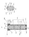
- FIG. 2 is a cross-sectional view of a main part of the desulfurizer 200 according to Embodiment 1 of the present invention.
- a flange portion 202 a formed to protrude outward is provided on the upper portion of the outer container main body 202.
- the flange portion 202a and the peripheral portion 220a of the lid portion 220 sandwich the outer container packing 215 therebetween and are pressed from above and below by the pressing portion 205, whereby the outer container 201 is kept airtight.
- this outer container packing 215 an O-ring made of synthetic rubber can be used.
- a cylindrical inner container 208 made of plastic is housed in the outer container body 202 and disposed.
- the inner container 208 corresponds to an example of the desulfurizing agent cartridge of the present invention.
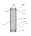
- FIG. 3 is a cross-sectional configuration diagram of the inner container 208 before being housed in the outer container 201.
- the inner vessel 208 is provided with a desulfurization part 221 in which a desulfurization agent 209 is accommodated.
- An inner container inlet 211 that is an inlet of the raw material to the desulfurization unit 221 is provided above the desulfurization unit 221, and an inner container outlet that is an outlet of the raw material from the desulfurization unit 221 is provided below the desulfurization unit 221.
- a part 212 is provided.
- a desulfurization agent retainer 210 made of a polypropylene nonwoven fabric is provided in order to suppress leakage of the desulfurization agent 209 from the inner container 208.
- the desulfurizing agent 209 uses zeolite that adsorbs sulfur components.
- the desulfurization agent retainer 210 is not limited to polypropylene, and any structure that holds the desulfurization agent 209 in the inner container 208 may be used. For example, a metal mesh, a punching plate, or the like can be used.
- a groove 222 for placing an inner container packing 214 is formed at the upper end of the inner container 208.
- the inner container inlet portion 211 and the inner container outlet portion 212 serve as opening portions for circulating the raw material, and the other portions have a container configuration capable of maintaining the airtightness of the raw material to be circulated.
- a circular seal member 218 as shown in FIG. 4 is provided at the inner container inlet 211 and the inner container outlet 212 of the inner container 208.
- the seal member 218 corresponds to an example of the partition wall portion of the present invention.
- the outer container 201 since the outer container 201 circulates a combustible raw material, in order to provide airtightness other than the outer container inlet portion 203 and the outer container outlet portion 204, the outer container 201 may be configured using a metal material. preferable.
- the inner container 208 may be made of a metal material as in the case of the outer container 201.
- the outer container 201 can maintain airtightness with the outside of the desulfurizer 200.
- the inner container 208 is made of plastic, a part of it may be made of metal.
- the inner container 208 has an outer container main body 202 such that the inner container inlet portion 211 faces the outer container inlet portion 203 and the inner container outlet portion 212 faces the outer container outlet portion 204. It is stored in.
- a spacer 213 for providing a gap with the inner container 208 is provided at the bottom of the outer container main body 202, and the inner container 208 is placed on the spacer 213.
- the outer container inlet 203 is provided with a protrusion 217 protruding toward the inner container inlet 211 (downward).
- the outer container outlet portion 204 is also formed with a protrusion 217 that protrudes toward the inner container outlet portion 212 (upward).
- the protrusions 217 provided on the lid 220 and the outer container main body 202 correspond to an example of the contact portion of the present invention.
- the sealing member 218 may be a sealing film that can be easily broken during storage.
- a resin film such as a polyethylene film may be used.
- an O-ring containing synthetic rubber as a component is provided in a groove 222 (see FIG. 3) at the upper portion of the inner container 208 in order to keep the outer container inlet 203 and the inner container inlet 211 airtight.
- An inner container packing 214 is provided. Similarly to the outer container packing 215 described above, the inner container packing 214 is configured to be kept airtight by applying a compressive force from the pressing portion 205. Note that the inner container packing 214 may be provided between the inner container 208 and the spacer 213.
- the outer container 201 is provided on the raw material piping, and the outer container inlet portion 203 and the outer container outlet portion 204 are connected to the raw material piping via a connecting portion (see desulfurization connecting portion 7 in FIG. 20 described later). Yes. By releasing the connection at this connection portion, the desulfurizer 200 of the present embodiment is removed from the raw material piping.
- the lid portion 220 is separated from the outer container main body 202. Thereafter, the inner container 208 is pulled out from the outer container body 202.
- the replacement inner container 208 is inserted into the outer container body 202 from above.
- the protrusion 217 breaks the seal member 218 on the inner container outlet 212 side, and the inner container outlet 212 and the outer container outlet 204 communicate with each other.
- the lid 220 is put on the outer container main body 202.
- the seal member 218 of the inner container inlet 211 is broken by the protrusion 217 of the lid 220, and the inner container inlet 211 and the outer container inlet 203 communicates.
- the pressing portion 205 is attached so as to sandwich the flange portion 202a of the outer container body 202 and the peripheral portion 220a of the lid portion 220, and the half members 205a and 205b are fixed by the screw fixing portion 207, so that the replacement work can be performed. finish.
- the inner container 208 is accommodated in the outer container 201, and the protrusions 217 of the outer container inlet portion 203 and the outer container outlet portion 204 are connected to the inner container inlet portion 211 and When pushed into the inner container outlet part 212, the seal member 218 is broken, and the conduction between the inner container inlet part 211 and the outer container inlet part 203 and between the inner container outlet part 212 and the outer container outlet part 204 is ensured. .
- the desulfurization agent 209 before being stored in the outer container 201 can prevent adsorption of components that inhibit the adsorption of sulfur components, such as moisture absorption in the atmosphere, and can prevent desulfurization performance from deteriorating. .
- the outer container 201 and the inner container 208 have a double structure. Since 201 is made of metal, the inner container 208 can be made of plastic. By making the inner container 208 made of plastic in this way, molding becomes easy, and the weight is reduced when the inner container 208 is transported for replacement, thereby reducing the burden on the operator during maintenance. I can do it.
- the outer container 201 and the inner container 208 do not have a double structure as in the present embodiment, for example, one container is directly filled with a desulfurization agent.
- the container when replacing the used desulfurizing agent, the container may be replaced, or after the container is opened, the desulfurizing agent is dropped from the container by shaking or tilting, and only the desulfurizing agent is replaced. It was.
- the desulfurizing agent when each container is replaced, in order to reuse the filled desulfurizing agent, the desulfurizing agent may be taken out by taking it home to a factory and cutting the container.
- the desulfurizer 200 can be replaced without cutting the outer container 201 when the adsorption characteristics are reduced, and only the inner container 208 can be replaced. It becomes possible.
- the inner container 208 of the present embodiment is made of plastic, it is easy to cut the container in order to reuse and recycle the filled desulfurizing agent.
- the desulfurizing agent when the desulfurizing agent is taken out by shaking or tilting the outer container, the desulfurizing agent may be scattered during the work. When the desulfurizing agent is exposed to the atmosphere, the sulfur compound adsorbed on the desulfurizing agent is desorbed. As a result, odors are generated and the efficiency of the recovery work is reduced.
- the opening part of the inner container 208 is connected to the inner container inlet 211 and the inner container outlet 212. Limited. Therefore, when the inner container 208 is taken out, the portion of the inner container 208 where the desulfurizing agent 209 contacts the atmosphere can be reduced, and the amount of sulfur compounds desorbed from the desulfurizing agent 209 can be reduced, so the odor generation probability is reduced. it can.
- the desulfurization agent recovery workability can be improved, and the desulfurizer can be easily replaced at the installation site of the hydrogen generator and the fuel cell power generation system.
- the recovery workability of the desulfurizer 200 and the reusability / maintenance / recyclability of the outer container 201 can be improved with a simple configuration.
- the outer container inlet 203 is provided at the upper part of the outer container 201
- the inner container inlet 211 is provided at the upper part of the inner container 208
- the outer container inlet part. 203 and the inner container inlet 211 face each other.
- the outer container outlet portion 204 is provided in the lower portion of the outer container 201
- the inner container outlet portion 212 is provided in the lower portion of the inner container 208
- the outer container outlet portion 204 and the inner container outlet portion 212 face each other.
- the progress of desulfurization can be achieved by using a material that allows the inside of the inner container 208 to be seen through. Since it can be visually confirmed, the replacement time of the inner container 208 can be easily determined.
- a configuration can be realized by configuring the inner container 208 with a translucent or transparent resin material.
- a transparent see-through portion 216 may be provided on the side surface of the inner container 208 so that the desulfurization agent stored in the inner container 208 can be seen.
- the raw material is sent from the outer container inlet 203 to the inner container inlet 211 and passes through the desulfurizing agent 209 stored in the inner container 208 to be removed from the inner container outlet 212.
- the container outlet part 204 a raw material distribute
- the outer container outlet part 204 is made into the raw material inlet, and a raw material is sent from the direction opposite to the direction shown in this Embodiment 1. It may be configured (the raw material is distributed from the bottom to the top in FIG. 2).
- the protrusion 217 of the first embodiment has a cylindrical shape and the tip is formed horizontally, but the tip 227a is formed obliquely like the protrusion 227 shown in FIG. May be. Further, as shown in FIG. 6B, a protrusion 228 in which a sharp protrusion 228a is formed may be used.
- the seal member 218 can be easily broken by using the protruding portion having such a shape. Note that the formation of the protrusions 228a in this way corresponds to an example of the formation of the unevenness of the present invention.
- the sealing member 218, a thin material such as natural rubber used for a rubber balloon may be pulled and attached to the inner container inlet 211 and the inner container outlet 212.
- the seal member 218 is broken by the protrusion 217, the central portion is pulled to the periphery, so that the broken seal member 218 remains inside the inner container inlet portion 211 and the inner container outlet portion 212. It is possible to reduce the obstruction of the distribution of raw materials.
- a material with a curl from the center to the periphery may be used instead of a thin material such as natural rubber.
- a material with a curl from the center to the periphery may be used instead of a thin material such as natural rubber.
- the seal member since the seal member is wound around when the seal member is broken, it is possible to reduce the blockage of the raw material by the seal member after being broken.
- the lid portion 220 and the outer container main body 202 are fixed by the pressing portion 205, but the pressing portion 205 may not be used.
- Each of the lid 220 and the outer container body 202 may be formed with a screw, and may be an outer container 501 that is fixed by screwing.
- a screw portion 520b is formed downward from the edge portion 520a of the lid portion 520 of the desulfurizer 500 shown in FIG. 7, and a screw thread 520c is formed inside the screw portion 520b.
- a thread 502c is formed on the end surface of the flange portion 502a of the outer container body 502.
- the outer container body 502 and the lid part 520 can be fixed by screwing the thread 520c of the lid part 520 and the thread 502c of the outer container body 502.
- the space through which the raw material including the inner container 208 circulates is sealed by the inner container packing 214, and the space in the outer container 201 is sealed by the outer container packing 215.
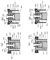
- Both the inner container packing 214 and the outer container packing 215 seal the space by being sandwiched from above and below, but the present invention is not limited to such a configuration, and as shown in FIG. It is good also as a structure which pinches
- the inner container packing 214 and the outer container packing 215 may be sandwiched from the left and right.
- a groove 250 is formed inside the inner container inlet 211, and the inner container packing 214 is arranged in the groove 250.
- the inner container packing 214 is sandwiched between the outer wall of the protrusion 217 and the inner wall of the inner container inlet 211, and the space in which the raw material flows is sealed.
- the seal member 218 is provided closer to the desulfurization part 221 than the groove 250 in the inner container inlet part 211.
- the seal member 218 after being broken is shown as a seal portion 218a.
- the packing holding portion 220 b is formed from the lower side of the lid portion 220 so as to be disposed in the space between the outer wall of the inner container 208 and the inner wall of the outer container main body 202.
- a groove 251 is formed on the outer peripheral side of the packing holding part 220b, and an outer container packing 215 is disposed.
- the outer container packing 215 is sandwiched between the outer wall of the packing holding part 220b and the inner wall of the outer container main body 202 to seal the space in the outer container 201.
- FIG. 8C is a modification to FIG. 8A
- FIG. 8D is a modification to FIG. 8C.
- the basic configuration of the desulfurizer of the second embodiment is the same as that of the first embodiment, but the configuration of the seal member is different. Therefore, this difference will be mainly described.
- symbol is attached
- FIG. 9A is a cross-sectional configuration diagram of the desulfurizer 800 according to the second exemplary embodiment of the present invention.
- FIG. 9B is an enlarged cross-sectional configuration diagram in the vicinity of the inner container inlet portion 211 of FIG.
- FIG. 10A is a plan view of the seal member according to the second embodiment.
- FIG. 10B is a cross-sectional view taken along the line AA ′ in FIG.
- the seal member 818 corresponding to an example of the partition wall portion of the present invention is configured to be easily broken by making a cut 819 in the seal member 818.
- FIG. 10A a plurality of cuts 819 are formed from the center 818a of the circular seal member toward the peripheral portion 818b.
- FIG.10 (b) is AA 'sectional drawing of Fig.10 (a).
- the notch 819 is formed shorter than the thickness 818 w of the seal member 818, and the seal member 818 is not penetrated by the notch 819.
- the width of the notch 819 and the thickness 818w of the seal member 818 are shown larger than actual for the purpose of explanation.
- the cut 819 that does not penetrate through the seal member 818 corresponds to an example of the groove-shaped cut of the present invention.
- the elastic portion 820 is pushed and expanded toward the peripheral edge portion 818 b by the protrusion 217, and the outer container inlet portion 203 and the inner container inlet portion 211. There is communication between.
- the inner container outlet 212 and the outer container outlet 204 communicate with each other with the same configuration.
- the seal member 818 is elastic so as to close the inner container inlet portion 211 and the inner container outlet portion 212. It returns to its original shape by force.
- the areas of the opening portions of the inner container inlet portion 211 and the inner container outlet portion 212 can be reduced.
- the probability that the desulfurization agent 209 in the inner container 808 comes into contact with the atmosphere can be further reduced.
- the inner container 808 when the unused inner container 808 for replacement is transported, the inner container 808 is hermetically sealed by the seal member 818, so that adsorption of moisture or the like to the desulfurization agent is prevented. I can do it. Further, when the used inner container 808 is taken out, the seal member 818 returns so as to block the inner container inlet portion 211 and the inner container outlet portion 212, so that the opening area is reduced and the odor is diffused into the atmosphere. It can be reduced, and the efficiency of the collection work can be improved.
- seal member 226 in which the notch 225 is not formed up to the peripheral edge but is formed only near the center may be used.
- the notch 223 may penetrate the thickness 224W of the seal member 224 from the state of the unused inner container.
- . 12A is a plan view of the seal member 224
- FIG. 12B is a cross-sectional view taken along line AA ′ of FIG.
- the sealing member 224 having such a configuration the sealing property when not in use is worse than that of the sealing member 818 of the second embodiment, but the contact area between the desulfurizing agent and air is in the portion of the notch 223. Since it is limited, the adsorption
- the notch 223 penetrating through the seal member 224 corresponds to an example of a slit-like notch according to the present invention.
- the protrusions 227 and 228 shown in FIGS. 6A and 6B may be used.
- Embodiment 3 Below, the desulfurizer 300 in Embodiment 3 concerning this invention is demonstrated.
- the desulfurizer 300 of the third embodiment has the same basic configuration as that of the first embodiment, but differs in the configuration of the inner container outlet and the outer container outlet. Therefore, it demonstrates centering on difference with Embodiment 1.
- FIG. 1 the same code
- FIG. 1 is attached
- FIG. 13 is a cross-sectional view of a main part of the desulfurizer 300 according to Embodiment 3 of the present invention.
- the outer container outlet 304 of the outer container 301 is provided on the side surface of the outer container main body 302.
- a plurality of L-shaped protrusions 317 are provided from the lower inner wall of the outer container main body 302 instead of the protrusions 217 of the outer container outlet part 204 of the first embodiment.
- FIG. 14A is a front view of the inner container 308 before being housed in the outer container 301.
- FIG. 14B is a front view of the inner container 308 when housed in the outer container 301.
- a plurality of inner container outlet portions 312 are provided on the side surface in a circular shape.
- a seal member 318 is provided so as to surround the plurality of inner container outlet portions 312 so that the inner container outlet portion 312 does not communicate with the atmosphere before replacement.
- a desulfurization agent presser 310 for preventing the desulfurization agent from leaking is provided inside the inner container 308 so as to surround the inner container outlet 312.
- the inner container 308 corresponds to an example of the desulfurizing agent cartridge of the present invention.
- the raw material that has passed through the inner container 308 and exited from the inner container outlet 312 is separated from the outer wall of the inner container 308 and the outer container 301. It passes through a space (see S in the figure) formed by the inner wall and is sent to the outer container outlet 304.
- the first embodiment Since the removal operation of the outer container inlet portion 203 and the outer container outlet portion 204 does not interfere with each other, the removal operation is facilitated.
- the outer container inlet portion 203 and the outer container outlet portion 204 are vertically arranged.
- the desulfurizer 200 is used in order to remove the outer container inlet portion 203 from the pipe. If it is going to move downward, it will be difficult to move because it interferes with the connection between the outer container outlet 204 provided below and the piping.
- the outer container inlet portion 203 and the outer container outlet portion 304 are arranged on the upper and side surfaces.
- the desulfurizer 300 is removed. Therefore, the desulfurizer 300 can be removed smoothly without interfering with the connection portion between the outer container outlet 304 and the pipe.
- the outer container outlet portion 304 is provided on the side surface of the outer container main body 302.
- the outer container outlet portion 304 is not limited to this position, and the outer container outlet portion of the desulfurizer 400 shown in FIG. Like 404, you may arrange
- the raw material from which the sulfur component has been removed through the inner container 308 exits from the inner container outlet 312 and is constituted by the outer wall of the inner container and the inner wall of the outer container 401 (the inner wall of the outer container main body 402). And move upward through the space (see T in the figure) and sent to the outer container outlet 404.
- the outer container outlet portion 404 By providing the outer container outlet portion 404 on the same surface as the outer container inlet portion 203 in this way, for example, when removing the outer container inlet portion 203 and the outer container outlet portion 404 connected to other pipes, the same upper side Can be done. Therefore, similarly to the configuration shown in FIG. 13, when removing the outer container outlet 404 and the outer container inlet 203, there is a space for moving the desulfurizer 400 below, so that the desulfurizer 400 can be removed smoothly without interference. The removal work becomes easy.
- the basic configuration of the desulfurizer of the fourth embodiment is the same as that of the first embodiment, but the configuration of the partition walls is different. Therefore, this difference will be mainly described.
- symbol is attached
- FIG. 16 is a cross-sectional configuration diagram of a desulfurizer 600 according to the fourth embodiment.
- FIG. 17 is a cross-sectional configuration diagram of the inner container 608 of the fourth embodiment.
- FIG. 18A is an enlarged view of the vicinity of the inner container inlet 611.
- FIG. 18B is an enlarged view of the vicinity of the inner container inlet 611, and shows a state where the presser 205 is removed and the lid 620 is removed from the outer container main body 602.
- the inner container 608 corresponds to an example of the desulfurizing agent cartridge of the present invention.
- the inner vessel 608 of the desulfurizer 600 is provided with a wall 650 in which a through hole 650a is formed in the inner vessel inlet 611.
- a sealing member 651 for sealing the through hole 650 a when the inner container 608 is removed from the outer container 601 is provided in the inner container inlet 611.
- the sealing member 651 is a truncated cone-shaped member whose width decreases toward the outside of the inner container 608, and a packing 652 is provided around the sealing member 651.
- the sealing member 651 has a protrusion 651 a formed on the upper surface thereof toward the outside of the inner container 608.
- a spring member 653 having one end fixed to the desulfurizing agent presser 210 and the other end fixed to the bottom surface of the sealing member 651 is provided.
- the inner wall of the through hole 650a is configured to have a taper shape that becomes wider toward the inside in accordance with the shape of the sealing member 651.
- the spring member 653 corresponds to an example of the elastic member of the present invention.
- An example of the partition wall portion of the present invention corresponds to the wall portion 650, the sealing member 651, the packing 652, and the spring member 653.
- the inner container outlet 612 is also provided with a wall 650, a sealing member 651, a packing 652, and a spring member 653.
- the outer container 601 is also provided with a wall 660 in which a through hole 660a is formed in the outer container inlet 603.
- the outer container inlet 603 is also provided with a sealing member 651, packing 652, and a spring member 653.
- One end of the spring member 653 is fixed to a support member 661 protruding from the inner wall of the outer container inlet 603.
- the outer container outlet 604 is also provided with a wall 660, a sealing member 651, a packing 652, a spring member 653, and a support member 661.
- the sealing member 651 provided in the outer container inlet portion 603 and the outer container outlet portion 604 corresponds to an example of the contact portion of the present invention.
- the sealing member 651 moves from the through holes 650a and 660a
- the outer container inlet 603 and the inner container inlet 611 communicate with each other.
- the inner container outlet 612 and the outer container outlet 604 communicate with each other.
- the sealing member 651 contacts the wall 660 by the elastic force of the spring member 653, and the through hole 660a is sealed.
- the through holes 650a and 660a are also sealed in the inner container outlet 612 and the outer container outlet 604.
- the outer container inlet 603 and the outer container outlet 604 are provided with the sealing member 651, the spring member 653, and the like.
- the sealing member 651, the spring member 653, and the like are not provided, and a protrusion is provided.
- the configuration for sealing the inner container inlet 611 and the inner container outlet 612 is different from that of the fourth embodiment.
- FIG. 19A is a cross-sectional configuration diagram showing a desulfurizer 700 according to the fifth embodiment.
- FIG. 19B is an enlarged view of the vicinity of the inner container inlet 711.
- FIG. 20 is a cross-sectional configuration diagram of the inner container 708 of the fourth embodiment.
- the inner container 708 corresponds to an example of the desulfurizing agent cartridge of the present invention.
- the desulfurizer 700 is formed with a wall portion 750 having a through hole 710 a at the tip of the inner container inlet 711.
- a groove 750 b is formed in the inner wall of the wall portion 750, and the inner container packing 214 is disposed.
- a sealing member 751 for sealing the through hole 750 a when the inner container 708 is removed from the outer container 701 is provided in the inner container inlet 711.
- the sealing member 751 is a spherical member.
- a spring member 753 having one end fixed to a support member 730 formed on the inner wall of the inner container inlet 711 and the other end fixed to the bottom of the sealing member 751 is provided.
- the spring member 753 corresponds to an example of the elastic member of the present invention.
- An example of the partition wall portion of the present invention corresponds to the wall portion 750, the sealing member 751, the spring member 753, and the support member 730.
- the inner container outlet 712 is also provided with a wall 750, a sealing member 751, an inner container packing 214, and a spring member 753.
- the outer container 701 is provided with a protrusion 717 at the outer container inlet 703 of the lid 720 toward the lower side.
- a plurality of through holes 717 a are formed in the side wall near the tip of the protrusion 717.
- a protrusion 717 is also provided on the outer container outlet 704 of the outer container main body 702 upward. This protrusion 717 corresponds to an example of the contact portion of the present invention.
- the sealing member 751 in a state where the inner container 708 is attached to the outer container 701, the sealing member 751 is pushed toward the desulfurization part 221 by the protrusion 717 of the outer container 701, The sealing member 751 has moved inward from the through hole 710a.
- the outer container inlet 703 and the inner container inlet 711 communicate with each other through a plurality of through holes 717 a formed at the tip of the protrusion 717.
- the inner container outlet 712 and the outer container outlet 704 are also communicated.
- the sealing member 751 when the inner container 708 is taken out from the outer container 701, the sealing member 751 is released from the pressing of the protruding portion 717, and thus the elasticity of the spring member 753. It is urged toward the wall portion 750 by the force and comes into contact with the wall portion 750. By this operation, the sealing member 751 seals the through hole 710a. Similarly, the through hole 750a of the inner container outlet 712 is also sealed.
- the inner container inlet portion 711 and the inner container outlet portion 712 of the inner container 708 are sealed. Can be prevented from diffusing into the atmosphere.
- the spring member 753 is fixed to the support member 730.
- the desulfurizing agent presser 210 is formed of a metal mesh or the like, it may be fixed directly to the desulfurizing agent presser 210.
- a support member may be formed on the inner container inlet 611 and the inner container outlet 621, and one end of the spring member 653 may be fixed to the support member. .
- the desulfurization agent 209 is filled in the inner container to constitute the desulfurization part 221, but a plurality of containers filled with the desulfurization agent 209 are connected to constitute the desulfurization part. May be.
- the inner container 908 having such a configuration is shown in FIG. As shown in the figure, the inner container 908 is provided with an inner container main body 909 and a lid 910 disposed on the upper portion of the inner container main body 909. A convex portion 910a is formed on the periphery of the lid portion 910 downward, and a screw thread 910b is formed on the inner side of the convex portion. A thread 909 b is also formed on the outer wall of the upper part of the inner container body 909.
- a groove is formed at the upper end of the inner container main body 909, and a packing 911 is provided in the groove.
- the screw 909b of the inner container main body 909 and the screw thread 910b of the lid 910 are screwed together and tightened, whereby the packing 911 is pressed by the lid 910 and the inner container main body 909, and the inside of the inner container 908 is sealed.
- the inner container main body 909 is provided with three desulfurization members 912 that are filled with a desulfurization agent 209.
- a desulfurization section 920 is constituted by these three connected desulfurization members 912.
- FIG. 21B is a cross-sectional configuration diagram of the desulfurization member 912.
- the desulfurization member 912 is obtained by filling a container 913 with a desulfurization agent 209, and the upper and lower portions of the container 913 are opened.
- a desulfurization agent presser is provided in the upper and lower portions so that the desulfurization agent 209 does not leak.
- 210 is provided.
- an O-ring 914 is provided on the side wall to prevent the raw material from flowing between the inner wall of the inner container body 909 and the outer wall of the container 913.
- the unused desulfurization member 912 is the most downstream ( It is more preferable to arrange the third one from the top in the figure.
- FIG. 22B is a cross-sectional configuration diagram of the desulfurization member 1012.
- the desulfurization member 1012 differs from the desulfurization member 912 described above in that a desulfurization member inlet portion 1021 is provided in the upper portion of the container 913 and a desulfurization member outlet portion 1022 is provided in the lower portion of the container 913. It has been.
- the desulfurization member outlet portion 1022 is provided with a seal member 218, and the desulfurization member inlet portion 1021 is provided with a seal member 1023.
- the seal member 1023 is a detachable seal unlike the seal member 218 described above.
- the three desulfurization members 1012 are connected to form a desulfurization section 1020.
- the three desulfurization members 1012 are connected by breaking the seal member 218 of the desulfurization member 1012 located above the desulfurization member inlet portion 1021 from which the seal member 1023 has been peeled off.
- the seal member 218 after being broken is shown as a seal portion 218a.
- the replacement desulfurization member 1012 When replacing one desulfurization member 1012 in the inner container 1008 having such a configuration, the replacement desulfurization member 1012 is disposed on the most downstream side of the inner container 1008 after the seal member 1023 is peeled off. The In this case, it is possible to prevent the desulfurization agent 209 filled in the replacement desulfurization member 1012 from being exposed to the air and being deteriorated.
- the peeled seal member 1023 may be used to seal the desulfurization member inlet portion 1021 of the desulfurization member 1012 taken out from the inner container 1008. Further, by using the seal member 818 as described in Embodiment 2 instead of the seal member 218, at the time of replacement of the desulfurization member 1012, at least the opening area of the desulfurization member outlet portion 1022 can be reduced. Odor can be reduced.
- FIG. 23 is a schematic diagram showing a fuel cell power generation system 100 according to Embodiment 6 of the present invention.
- the fuel cell power generation system 100 includes a hydrogen generator 1 that generates a hydrogen-containing gas and a fuel that generates power using the hydrogen-containing gas supplied from the hydrogen generator 1.
- a battery 8 a hydrogen-containing gas supply path 12 for supplying a hydrogen-containing gas from the hydrogen generator 1 to the fuel cell 8, an off-gas path 14 for guiding the hydrogen off-gas discharged from the fuel cell 8 to the hydrogen generator 1, and a combustion And a combustion gas supply path 15 for supplying gas to the hydrogen generator 1.
- the hydrogen-containing gas supply path 12 is provided with a sealing portion 9 that seals the supply of the hydrogen-containing gas from the hydrogen generator 1.
- the sealing unit 9 includes a hydrogen generator bypass path 11 that leads the raw material supplied from the raw material supply unit 4 to the outside before introducing the raw material into the reformer 5, and a hydrogen-containing gas supplied from the hydrogen generator 1. Is connected to the fuel cell bypass path 13 that returns the fuel cell 8 to the hydrogen generator 1 without supplying it to the fuel cell 8.
- the fuel cell bypass path 13, the offgas path 14, and the combustion gas supply path 15 are connected via a connection portion 25.
- the sealing unit 9 has a configuration in which a plurality of solenoid valves are combined (detailed description is omitted), and has a function of sealing or opening the hydrogen-containing gas supply path 12 and a gas supplied from the hydrogen generator 1 or It has a function of switching the gas flow so that the gas supplied from the hydrogen generator bypass path 11 is circulated through the hydrogen-containing gas supply path 12 or the fuel cell bypass path 13.
- the hydrogen generator 1 according to the sixth embodiment includes a desulfurizer 200 that removes sulfur components in the raw material described in the first embodiment, a water supply unit 3, and a raw material supply unit 4.
- the reformer 5 and the operation control unit 16 are provided.
- the water supply unit 3 is a water pump connected to the outside of the reformer 5 and having a flow rate adjusting function.
- the water supply unit 3 supplies water to the reformer 5 while adjusting the flow rate of water based on a command from the operation control unit 16.
- the raw material supply unit 4 is a booster pump having a flow rate adjusting function disposed on the raw material supply path 10 connecting the desulfurizer 200 and the reformer 5.
- the raw material supply unit 4 supplies the raw material to the reformer 5 while adjusting the flow rate of the raw material based on a command from the operation control unit 16.
- a hydrogen generator bypass path 11 is connected to the raw material supply path 10 on the downstream side of the raw material supply section 4 via a connection section 27.
- the desulfurizer 200 described in the first embodiment is connected to a city gas gas infrastructure line 6 as a raw material supply source.
- the raw material supplied from the gas infrastructure line 6 is controlled by the raw material supply unit 4 so as to correspond to the amount of hydrogen-containing gas necessary for the fuel cell 8 and is supplied to the desulfurizer 200.
- the desulfurizer 200 is disposed between the gas infrastructure line 6 and the raw material supply unit 4.
- the present invention is not limited to this, and the desulfurizer 200 may be disposed on the downstream side of the raw material supply unit 4. Good.
- the desulfurization connecting portion 7 is disposed on the upstream side (outer vessel inlet portion 203) and the downstream side (outer vessel outlet portion 204) of the desulfurizer 200.
- These desulfurization connection portions 7 are configured to be detachable using, for example, a screw joint or the like, so that the desulfurizer 200 can be easily detached from the piping such as the gas infrastructure line 6 at the time of replacement maintenance of the desulfurizer 200.
- only the inner container 208 may be replaced without removing the outer container 201 from the piping such as the gas infrastructure line 6.
- the reformer 5 includes a steam reforming unit 20 that generates a hydrogen-containing gas by reforming a raw material and steam, and carbon monoxide and steam in the hydrogen-containing gas generated by the steam reforming unit 20.
- a steam reforming unit 20 that generates a hydrogen-containing gas by reforming a raw material and steam, and carbon monoxide and steam in the hydrogen-containing gas generated by the steam reforming unit 20.
- the shift unit 24 that performs a shift reaction to reduce the carbon monoxide concentration
- the air supply unit 17 that supplies air to the hydrogen-containing gas after passing through the shift unit 24, and the air supplied from the air supply unit 17
- a selective oxidation unit 26 that mainly oxidizes and removes carbon monoxide remaining in the hydrogen-containing gas after passing through the transformation unit 24.
- the reformer 5 is provided with a reforming temperature detection unit 18 for detecting the temperature of the reforming catalyst (or hydrogen-containing gas) in the steam reforming unit 20, and the steam reforming unit is provided at the bottom thereof.
- a heating unit 2 for combusting combustion gas is provided in order to supply reaction heat necessary for the reforming reaction in the unit 20, a heating unit 2 for combusting combustion gas is provided.
- hydrogen-containing gas is generated using the raw material after passing through the desulfurizer 200 and the water supplied from the water supply unit 3.
- the steam reforming unit 20 is provided with a Ru-based reforming catalyst
- the shift unit 24 is provided with a Cu—Zn-based shift catalyst
- the selective oxidation unit 26 includes Is provided with a Ru-based selective oxidation catalyst.
- alteration part 24, and the selective oxidation part 26 is the same as that of a general reformer, detailed description is abbreviate
- the heating unit 2 includes an igniter 21 that serves as an ignition source of the heating unit 2, a combustion detection unit 22 that includes a flame rod that detects the combustion state of the heating unit 2, and a combustion fan 19 that supplies combustion air to the heating unit 2. have.
- a burner is used as the heating unit 2.
- the operation control unit 16 is a control unit that controls the operation of the hydrogen-containing gas of the hydrogen generator 1. That is, the operation control unit 16 stores operation information such as an operation sequence of the hydrogen generator 1 and an integrated raw material flow rate using a semiconductor memory, a CPU, etc., calculates an appropriate operation condition according to the situation, and Operating conditions can be instructed to the water supply unit 3, the raw material supply unit 4, and the like. For example, the operation control unit 16 uses the detection results in the reforming temperature detection unit 18 and the combustion detection unit 22 as inputs, and controls current pulses input to the water supply unit 3 and the raw material supply unit 4, electric power, and the like.
- the fuel cell power generation system 100 according to Embodiment 6 performs the same operation as a general fuel cell power generation system, and thus a detailed description thereof is omitted.
- the desulfurizer 200 described in the first embodiment is used.
- any desulfurizer described in the above embodiment may be used.
- the desulfurizer, the hydrogen generator using the desulfurizer, and the desulfurizing agent cartridge according to the present invention have an effect that the desulfurizing agent can be replaced more easily and the deterioration of the desulfurizing agent during the replacement can be suppressed. It is useful as a power generation system.
Landscapes
- Chemical & Material Sciences (AREA)
- Chemical Kinetics & Catalysis (AREA)
- Engineering & Computer Science (AREA)
- Organic Chemistry (AREA)
- Health & Medical Sciences (AREA)
- Analytical Chemistry (AREA)
- Inorganic Chemistry (AREA)
- Combustion & Propulsion (AREA)
- General Health & Medical Sciences (AREA)
- General Chemical & Material Sciences (AREA)
- Oil, Petroleum & Natural Gas (AREA)
- Biomedical Technology (AREA)
- Environmental & Geological Engineering (AREA)
- Hydrogen, Water And Hydrids (AREA)
- Fuel Cell (AREA)
- Separation Of Gases By Adsorption (AREA)
- Packages (AREA)
Abstract
Priority Applications (4)
| Application Number | Priority Date | Filing Date | Title |
|---|---|---|---|
| CN200980000278A CN101679892A (zh) | 2008-02-26 | 2009-02-24 | 脱硫器、氢生成装置、燃料电池发电系统及脱硫剂盒 |
| EP09714604A EP2248875A4 (fr) | 2008-02-26 | 2009-02-24 | Dispositif de désulfuration, appareil générant de l'hydrogène, système de génération électrique à pile à combustible et cartouche d'agent désulfurant |
| US12/597,373 US20100136439A1 (en) | 2008-02-26 | 2009-02-24 | Desulfurizer, hydrogen generation apparatus, fuel cell power generating system, and desulfurizing agent cartridge |
| JP2010500562A JP5410411B2 (ja) | 2008-02-26 | 2009-02-24 | 脱硫器、水素生成装置、燃料電池発電システム、及び脱硫剤カートリッジ |
Applications Claiming Priority (2)
| Application Number | Priority Date | Filing Date | Title |
|---|---|---|---|
| JP2008044200 | 2008-02-26 | ||
| JP2008-044200 | 2008-02-26 |
Publications (1)
| Publication Number | Publication Date |
|---|---|
| WO2009107362A1 true WO2009107362A1 (fr) | 2009-09-03 |
Family
ID=41015769
Family Applications (1)
| Application Number | Title | Priority Date | Filing Date |
|---|---|---|---|
| PCT/JP2009/000794 Ceased WO2009107362A1 (fr) | 2008-02-26 | 2009-02-24 | Dispositif de désulfuration, appareil générant de l'hydrogène, système de génération électrique à pile à combustible et cartouche d'agent désulfurant |
Country Status (5)
| Country | Link |
|---|---|
| US (1) | US20100136439A1 (fr) |
| EP (1) | EP2248875A4 (fr) |
| JP (1) | JP5410411B2 (fr) |
| CN (1) | CN101679892A (fr) |
| WO (1) | WO2009107362A1 (fr) |
Cited By (5)
| Publication number | Priority date | Publication date | Assignee | Title |
|---|---|---|---|---|
| JP2011132377A (ja) * | 2009-12-24 | 2011-07-07 | Noritz Corp | 脱硫器及びこれを備えた燃料電池システム |
| EP2558184A1 (fr) * | 2010-04-14 | 2013-02-20 | Süd-Chemie AG | Dispositif pour le traitement par adsorption d'un fluide ou d'un courant de fluide |
| US20140061098A1 (en) * | 2012-09-05 | 2014-03-06 | Yanhai Du | Systems and Methods for Liquid Fuel Desulfurization |
| JP2015229742A (ja) * | 2014-06-06 | 2015-12-21 | 本田技研工業株式会社 | 脱硫器 |
| GB2637383A (en) * | 2023-11-16 | 2025-07-23 | Johnson Matthey Davy Technologies Ltd | Improvements in or relating to catalyst carriers for tubular reactors |
Families Citing this family (7)
| Publication number | Priority date | Publication date | Assignee | Title |
|---|---|---|---|---|
| US20130252114A1 (en) | 2012-03-20 | 2013-09-26 | Pellion Technologies, Inc. | High voltage rechargeable magnesium cells having a non-aqueous electrolyte |
| CN105377413B (zh) * | 2013-07-01 | 2018-04-03 | 住友精密工业株式会社 | 蒸发装置及使用该装置的燃料电池系统 |
| DE102015008085A1 (de) | 2015-06-25 | 2016-12-29 | Mann+Hummel Gmbh | Entschwefelungsvorrichtung für eine Brennstoffzelle |
| CN107632049B (zh) * | 2016-07-19 | 2021-07-13 | 松下知识产权经营株式会社 | 检测系统 |
| DE102018212673A1 (de) * | 2018-07-30 | 2020-01-30 | Filtration Group Gmbh | Abgabevorrichtung |
| JP2021090911A (ja) * | 2019-12-10 | 2021-06-17 | 株式会社東芝 | 脱硫器及び燃料電池システム |
| CN115803919A (zh) * | 2020-05-22 | 2023-03-14 | 纽麦特技术有限公司 | 用于净化用于在燃料电池中使用的氢气的方法 |
Citations (4)
| Publication number | Priority date | Publication date | Assignee | Title |
|---|---|---|---|---|
| JPH08245970A (ja) * | 1995-03-09 | 1996-09-24 | Tokyo Gas Co Ltd | 都市ガスの付臭成分除去装置 |
| JPH1186892A (ja) * | 1997-09-09 | 1999-03-30 | Osaka Gas Co Ltd | 一酸化炭素除去システム及び一酸化炭素の除去方法 |
| JP2002037602A (ja) * | 2000-07-25 | 2002-02-06 | Matsushita Electric Ind Co Ltd | 水素生成装置 |
| JP2007084621A (ja) | 2005-09-20 | 2007-04-05 | Hagio Koatsu Yoki Kk | 脱硫剤カートリッジ |
Family Cites Families (15)
| Publication number | Priority date | Publication date | Assignee | Title |
|---|---|---|---|---|
| US2845138A (en) * | 1955-12-27 | 1958-07-29 | Wells Ind Corp | Desiccator unit |
| US4273750A (en) * | 1979-04-24 | 1981-06-16 | Energy And Pollution Controls, Inc. | Flue gas desulfurization apparatus and method |
| US4333752A (en) * | 1980-01-14 | 1982-06-08 | Michlin Chemical Corporation | Adsorbent cartridge for the exhaust of diazo process machines |
| US6604524B1 (en) * | 1999-10-19 | 2003-08-12 | 3M Innovative Properties Company | Manner of attaching component elements to filtration material such as may be utilized in respiratory masks |
| WO2003072150A1 (fr) * | 2002-02-28 | 2003-09-04 | Steris, Inc. | Systeme de vapeurs de peroxyde d'hydrogene a cartouche deshydratante remplaçable |
| EP1725318A4 (fr) * | 2004-03-19 | 2008-04-02 | Illinois Tool Works | Cartouche jetable pour sechoir a air/gaz |
| CA2628970C (fr) * | 2004-11-08 | 2014-01-21 | Trustees Of Tufts College | Appareil et procedes permettant la desulfuration regenerative et non regenerative des gaz chauds |
| EP1966229B1 (fr) * | 2005-09-12 | 2015-10-21 | Abela Pharmaceuticals, Inc. | Systèmes d'élimination de diméthylsulfoxyde (dmso), composés connexes ou odeurs associées à cette substance |
| KR101264330B1 (ko) * | 2006-02-18 | 2013-05-14 | 삼성에스디아이 주식회사 | 연료전지용 연료가스의 탈황 장치 및 이를 이용한 탈황방법 |
| KR100818256B1 (ko) * | 2006-08-11 | 2008-04-01 | 삼성에스디아이 주식회사 | 탈황기의 상태 측정 방식이 개선된 연료개질기와 그것을 갖춘 연료전지 장치 및 그 운영방법 |
| JP5126946B2 (ja) * | 2007-03-28 | 2013-01-23 | 株式会社豊田中央研究所 | 硫黄系ガス除去フィルタ及びそれを用いた硫黄系ガスの除去方法 |
| US7993616B2 (en) * | 2007-09-19 | 2011-08-09 | C-Quest Technologies LLC | Methods and devices for reducing hazardous air pollutants |
| US7896952B2 (en) * | 2008-04-14 | 2011-03-01 | Delphi Technologies, Inc. | Cartridge adsorber system for removing hydrogen sulfide from reformate |
| US8894751B2 (en) * | 2009-10-05 | 2014-11-25 | Separation Design Group Llc | Ultra rapid cycle portable oxygen concentrator |
| WO2012118737A2 (fr) * | 2011-03-01 | 2012-09-07 | Exxonmobil Research And Engineering Company | Procédé d'absorption modulée en température pour la séparation d'une espèce cible d'un mélange gazeux |
-
2009
- 2009-02-24 EP EP09714604A patent/EP2248875A4/fr not_active Withdrawn
- 2009-02-24 US US12/597,373 patent/US20100136439A1/en not_active Abandoned
- 2009-02-24 JP JP2010500562A patent/JP5410411B2/ja not_active Expired - Fee Related
- 2009-02-24 CN CN200980000278A patent/CN101679892A/zh active Pending
- 2009-02-24 WO PCT/JP2009/000794 patent/WO2009107362A1/fr not_active Ceased
Patent Citations (4)
| Publication number | Priority date | Publication date | Assignee | Title |
|---|---|---|---|---|
| JPH08245970A (ja) * | 1995-03-09 | 1996-09-24 | Tokyo Gas Co Ltd | 都市ガスの付臭成分除去装置 |
| JPH1186892A (ja) * | 1997-09-09 | 1999-03-30 | Osaka Gas Co Ltd | 一酸化炭素除去システム及び一酸化炭素の除去方法 |
| JP2002037602A (ja) * | 2000-07-25 | 2002-02-06 | Matsushita Electric Ind Co Ltd | 水素生成装置 |
| JP2007084621A (ja) | 2005-09-20 | 2007-04-05 | Hagio Koatsu Yoki Kk | 脱硫剤カートリッジ |
Non-Patent Citations (1)
| Title |
|---|
| See also references of EP2248875A4 * |
Cited By (6)
| Publication number | Priority date | Publication date | Assignee | Title |
|---|---|---|---|---|
| JP2011132377A (ja) * | 2009-12-24 | 2011-07-07 | Noritz Corp | 脱硫器及びこれを備えた燃料電池システム |
| EP2558184A1 (fr) * | 2010-04-14 | 2013-02-20 | Süd-Chemie AG | Dispositif pour le traitement par adsorption d'un fluide ou d'un courant de fluide |
| US20140061098A1 (en) * | 2012-09-05 | 2014-03-06 | Yanhai Du | Systems and Methods for Liquid Fuel Desulfurization |
| US9238781B2 (en) * | 2012-09-05 | 2016-01-19 | University Of South Carolina | Systems and methods for liquid fuel desulfurization |
| JP2015229742A (ja) * | 2014-06-06 | 2015-12-21 | 本田技研工業株式会社 | 脱硫器 |
| GB2637383A (en) * | 2023-11-16 | 2025-07-23 | Johnson Matthey Davy Technologies Ltd | Improvements in or relating to catalyst carriers for tubular reactors |
Also Published As
| Publication number | Publication date |
|---|---|
| JPWO2009107362A1 (ja) | 2011-06-30 |
| JP5410411B2 (ja) | 2014-02-05 |
| US20100136439A1 (en) | 2010-06-03 |
| CN101679892A (zh) | 2010-03-24 |
| EP2248875A4 (fr) | 2013-03-20 |
| EP2248875A1 (fr) | 2010-11-10 |
Similar Documents
| Publication | Publication Date | Title |
|---|---|---|
| JP5410411B2 (ja) | 脱硫器、水素生成装置、燃料電池発電システム、及び脱硫剤カートリッジ | |
| JP4832614B2 (ja) | 水素生成装置、及び燃料電池システム | |
| JP5636001B2 (ja) | 水素生成装置、燃料電池システム、及び水素生成装置の運転方法 | |
| JP5789780B2 (ja) | 燃料電池システムおよび燃料電池システムの運転方法 | |
| US9490495B2 (en) | Hydrogen generator, fuel cell system, and method of operating hydrogen generator | |
| WO2013001753A1 (fr) | Dispositif de génération d'hydrogène et système de pile à combustible | |
| JP5647909B2 (ja) | 水素生成装置および燃料電池システムの運転方法 | |
| US20110008688A1 (en) | Hydrogen production device, and fuel cell system provided with the same | |
| JP2014058426A (ja) | 水素生成装置及び燃料電池システム | |
| JP2010195623A (ja) | 水素生成装置、及び水素生成装置の運転方法 | |
| JP6791740B2 (ja) | 燃料電池発電システム | |
| JP4974562B2 (ja) | 燃料電池システムにおける機器の脱着方法及び装置 | |
| JP5451896B2 (ja) | 水素生成装置および燃料電池システム | |
| JP2011253705A (ja) | 燃料電池システム | |
| JP2013168299A (ja) | 燃料電池システム | |
| JP5505779B2 (ja) | 脱硫器及びこれを備えた燃料電池システム | |
| JP2002037602A (ja) | 水素生成装置 | |
| JP2008044845A (ja) | 水素生成システム | |
| KR20220100347A (ko) | 탈황기 및 이를 구비하는 연료전지 |
Legal Events
| Date | Code | Title | Description |
|---|---|---|---|
| WWE | Wipo information: entry into national phase |
Ref document number: 200980000278.6 Country of ref document: CN |
|
| ENP | Entry into the national phase |
Ref document number: 2010500562 Country of ref document: JP Kind code of ref document: A |
|
| WWE | Wipo information: entry into national phase |
Ref document number: 2009714604 Country of ref document: EP |
|
| WWE | Wipo information: entry into national phase |
Ref document number: 12597373 Country of ref document: US |
|
| 121 | Ep: the epo has been informed by wipo that ep was designated in this application |
Ref document number: 09714604 Country of ref document: EP Kind code of ref document: A1 |
|
| NENP | Non-entry into the national phase |
Ref country code: DE |