WO2009107536A1 - Film antireflet, plaque de polarisation antireflet et dispositif d'affichage d'image - Google Patents
Film antireflet, plaque de polarisation antireflet et dispositif d'affichage d'image Download PDFInfo
- Publication number
- WO2009107536A1 WO2009107536A1 PCT/JP2009/052868 JP2009052868W WO2009107536A1 WO 2009107536 A1 WO2009107536 A1 WO 2009107536A1 JP 2009052868 W JP2009052868 W JP 2009052868W WO 2009107536 A1 WO2009107536 A1 WO 2009107536A1
- Authority
- WO
- WIPO (PCT)
- Prior art keywords
- film
- resin
- hard coat
- antiglare
- coat layer
- Prior art date
- Legal status (The legal status is an assumption and is not a legal conclusion. Google has not performed a legal analysis and makes no representation as to the accuracy of the status listed.)
- Ceased
Links
Images








Classifications
-
- G—PHYSICS
- G02—OPTICS
- G02B—OPTICAL ELEMENTS, SYSTEMS OR APPARATUS
- G02B5/00—Optical elements other than lenses
- G02B5/02—Diffusing elements; Afocal elements
- G02B5/0205—Diffusing elements; Afocal elements characterised by the diffusing properties
- G02B5/021—Diffusing elements; Afocal elements characterised by the diffusing properties the diffusion taking place at the element's surface, e.g. by means of surface roughening or microprismatic structures
- G02B5/0221—Diffusing elements; Afocal elements characterised by the diffusing properties the diffusion taking place at the element's surface, e.g. by means of surface roughening or microprismatic structures the surface having an irregular structure
-
- G—PHYSICS
- G02—OPTICS
- G02B—OPTICAL ELEMENTS, SYSTEMS OR APPARATUS
- G02B1/00—Optical elements characterised by the material of which they are made; Optical coatings for optical elements
- G02B1/10—Optical coatings produced by application to, or surface treatment of, optical elements
- G02B1/14—Protective coatings, e.g. hard coatings
-
- G02B1/105—
-
- G—PHYSICS
- G02—OPTICS
- G02B—OPTICAL ELEMENTS, SYSTEMS OR APPARATUS
- G02B5/00—Optical elements other than lenses
- G02B5/02—Diffusing elements; Afocal elements
- G02B5/0205—Diffusing elements; Afocal elements characterised by the diffusing properties
- G02B5/0236—Diffusing elements; Afocal elements characterised by the diffusing properties the diffusion taking place within the volume of the element
- G02B5/0242—Diffusing elements; Afocal elements characterised by the diffusing properties the diffusion taking place within the volume of the element by means of dispersed particles
-
- G—PHYSICS
- G02—OPTICS
- G02B—OPTICAL ELEMENTS, SYSTEMS OR APPARATUS
- G02B5/00—Optical elements other than lenses
- G02B5/02—Diffusing elements; Afocal elements
- G02B5/0268—Diffusing elements; Afocal elements characterized by the fabrication or manufacturing method
-
- G—PHYSICS
- G02—OPTICS
- G02B—OPTICAL ELEMENTS, SYSTEMS OR APPARATUS
- G02B5/00—Optical elements other than lenses
- G02B5/02—Diffusing elements; Afocal elements
- G02B5/0273—Diffusing elements; Afocal elements characterized by the use
- G02B5/0278—Diffusing elements; Afocal elements characterized by the use used in transmission
-
- G—PHYSICS
- G02—OPTICS
- G02B—OPTICAL ELEMENTS, SYSTEMS OR APPARATUS
- G02B5/00—Optical elements other than lenses
- G02B5/02—Diffusing elements; Afocal elements
- G02B5/0273—Diffusing elements; Afocal elements characterized by the use
- G02B5/0294—Diffusing elements; Afocal elements characterized by the use adapted to provide an additional optical effect, e.g. anti-reflection or filter
-
- G—PHYSICS
- G02—OPTICS
- G02B—OPTICAL ELEMENTS, SYSTEMS OR APPARATUS
- G02B5/00—Optical elements other than lenses
- G02B5/02—Diffusing elements; Afocal elements
-
- G—PHYSICS
- G02—OPTICS
- G02F—OPTICAL DEVICES OR ARRANGEMENTS FOR THE CONTROL OF LIGHT BY MODIFICATION OF THE OPTICAL PROPERTIES OF THE MEDIA OF THE ELEMENTS INVOLVED THEREIN; NON-LINEAR OPTICS; FREQUENCY-CHANGING OF LIGHT; OPTICAL LOGIC ELEMENTS; OPTICAL ANALOGUE/DIGITAL CONVERTERS
- G02F1/00—Devices or arrangements for the control of the intensity, colour, phase, polarisation or direction of light arriving from an independent light source, e.g. switching, gating or modulating; Non-linear optics
- G02F1/01—Devices or arrangements for the control of the intensity, colour, phase, polarisation or direction of light arriving from an independent light source, e.g. switching, gating or modulating; Non-linear optics for the control of the intensity, phase, polarisation or colour
- G02F1/13—Devices or arrangements for the control of the intensity, colour, phase, polarisation or direction of light arriving from an independent light source, e.g. switching, gating or modulating; Non-linear optics for the control of the intensity, phase, polarisation or colour based on liquid crystals, e.g. single liquid crystal display cells
- G02F1/133—Constructional arrangements; Operation of liquid crystal cells; Circuit arrangements
- G02F1/1333—Constructional arrangements; Manufacturing methods
- G02F1/1335—Structural association of cells with optical devices, e.g. polarisers or reflectors
- G02F1/133502—Antiglare, refractive index matching layers
Definitions
- the present invention is not anti-glare while exhibiting excellent anti-glare performance, does not cause glare when applied to an image display device, exhibits high contrast, and provides good visibility, an anti-glare film.
- the present invention relates to an antiglare polarizing plate and an image display device using the antiglare film.
- Image display devices such as a liquid crystal display, a plasma display panel, a cathode ray tube (CRT) display, and an organic electroluminescence (EL) display, when external light is reflected on the display surface, remarkably deteriorates the visibility.
- display is performed using a television or a personal computer that emphasizes image quality, a video camera and a digital camera that are used outdoors with strong external light, and reflected light.
- a film layer that prevents reflection of external light is provided on the surface of an image display device.
- anti-reflection processing technology that uses interference by optical multilayer film and anti-glare processing technology that blurs the reflected image by scattering incident light by forming fine irregularities on the film layer surface are common. It is used for.
- the latter technique of scattering incident light by forming fine irregularities can be manufactured at a relatively low cost, and is therefore widely used in applications such as large monitors and personal computers.
- an antiglare film for example, a resin solution in which a filler is dispersed is applied on a base sheet by adjusting the film thickness, and the filler is exposed on the surface of the coating film, thereby causing random surface irregularities. It is manufactured by a method of forming on a base sheet.
- Patent Document 1 Japanese Patent Application Laid-Open No. 2002-189106 discloses a three-dimensional 10-point average roughness and a three-dimensional roughness standard on a transparent resin film.
- An antiglare film in which a cured product layer of an ionizing radiation curable resin layer having fine surface irregularities each having an average distance between adjacent convex portions on a surface satisfying a predetermined value is laminated.
- This antiglare film is manufactured by curing the ionizing radiation curable resin in a state where the ionizing radiation curable resin is sandwiched between the embossing mold and the transparent resin film.
- a conventional anti-glare film is arranged on the surface of the image display device, there is a problem that the entire display surface becomes whitish due to scattered light and the display becomes cloudy, so-called whitening is likely to occur. It was.
- Patent Document 2 Japanese Patent Application Laid-Open No. 2007-101912
- the present invention has been made in view of the present situation, and the object thereof is to provide a high-definition image display device in which deterioration in visibility due to whitish is prevented while exhibiting excellent anti-glare performance. Another object of the present invention is to provide an antiglare film that exhibits high contrast without causing glare. Another object of the present invention is to provide an antiglare polarizing plate and an image display device to which the antiglare film is applied.
- the inventors of the present invention include at least a transparent resin layer and a light diffusion layer containing fine particles having a refractive index different from the refractive index of the binder resin, and the surface thereof.
- a hard coat layer having a fine concavo-convex surface on the surface of the resin base film consisting of a fine concavo-convex surface having a specific shape the internal scattering characteristics and reflection characteristics of the antiglare film can be independently obtained.
- an antiglare film can be obtained in which glare is sufficiently prevented and contrast is hardly lowered when applied to an image display device.
- the present invention has been completed based on such findings and further various studies.
- the present invention comprises a multilayer structure including at least one transparent resin layer made of a transparent resin, and at least one light diffusion layer containing a transparent binder resin and fine particles having a refractive index different from that of the transparent binder resin.
- the present invention relates to an antiglare film comprising a resin base film and a hard coat layer laminated on the surface of the resin base film.
- the hard coat layer side surface of the resin base film is composed of a first fine uneven surface having a fine uneven shape, and an arithmetic average in an arbitrary cross-sectional curve of the first fine uneven surface
- the height Pa 1 is 0.4 ⁇ m or more and 2 ⁇ m or less
- the average length PSm 1 is 2 ⁇ m or more and 40 ⁇ m or less.
- the surface of the hard coat layer opposite to the resin base film side is composed of a second fine uneven surface having a fine uneven shape, and an arithmetic average height in an arbitrary cross-sectional curve of the second fine uneven surface.
- the thickness Pa 2 is 0.2 ⁇ m or more and 0.6 ⁇ m or less, the average length PSm 2 is 20 ⁇ m or more and 100 ⁇ m or less, and the arithmetic average height Pa 2 in an arbitrary cross-sectional curve of the second fine uneven surface is It is smaller than the arithmetic average height Pa 1 in an arbitrary cross-sectional curve of the first fine uneven surface of the material film.
- the internal haze of the resin base film is preferably 5% or more and 30% or less. Further, the surface haze of the hard coat layer laminated on the first fine uneven surface of the resin base film is 0.5% or more and 15% or less, and the internal haze of the hard coat layer is 2% or less. Preferably there is. More preferably, the internal haze of the hard coat layer is substantially 0%.
- the thickness of the resin base film is preferably 30 ⁇ m or more and 250 ⁇ m or less, and the thickness of the hard coat layer is preferably 1 ⁇ m or more and 10 ⁇ m or less.
- both the transparent resin which comprises a transparent resin layer, and the transparent binder resin which comprises a light-diffusion layer are acrylic resins.
- the resin base film has a two-layer structure of one transparent resin layer and one light diffusion layer laminated on the surface of the transparent resin layer.
- the hard coat layer is disposed on the surface of the light diffusion layer opposite to the transparent resin layer side.
- the resin base film has a three-layer structure of two transparent resin layers and a light diffusion layer disposed between the two transparent resin layers.
- the antiglare film of the present invention may further have a low reflection film on the second fine uneven surface of the hard coat layer.
- the present invention also provides an antiglare polarizing plate comprising any one of the above antiglare films and a polarizing film laminated on the antiglare film.
- the polarizing film is disposed on the resin base film side of the antiglare film.
- the antiglare film or the antiglare polarizing plate of the present invention can be combined with an image display element such as a liquid crystal display element or a plasma display panel to form an image display device. That is, according to the present invention, the antiglare film according to any one of the above or the antiglare polarizing plate and an image display element are provided, and the antiglare film or the antiglare polarizing plate has a hard coat layer side. An image display device is provided that is disposed on the outside of the image display element on the viewing side.
- the anti-glare film of the present invention exhibits excellent anti-glare performance, prevents deterioration of visibility due to whitening, and also generates glare when placed on the surface of a high-definition image display device. And high contrast can be exhibited.
- the anti-glare polarizing plate obtained by combining the anti-glare film of the present invention with a polarizing film also exhibits the same effect.
- positioned the anti-glare film or anti-glare polarizing plate of this invention has high anti-glare performance, and is excellent in visibility.
- FIG. 1 It is a cross-sectional schematic diagram which shows the preferable example of the anti-glare film of this invention. Schematic representation of incident light direction and transmitted scattered light intensity measurement direction when measuring the scattered light intensity observed in the normal direction of the hard coat layer side when light is incident from the resin base film side of the antiglare film It is a perspective view shown in FIG. It is an example of the graph which plotted the relative scattered light intensity
- 6 is a graph showing transmission / scattering profiles of antiglare films obtained in Comparative Examples 1 to 3.
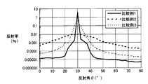
- 6 is a graph showing reflection profiles of antiglare films obtained in Comparative Examples 1 to 3. It is a graph showing the transmission-scattering profile of the anti-glare film obtained in Comparative Examples 4 and 5. It is a graph showing the reflection profile of the anti-glare film obtained in Comparative Examples 4 and 5.
- FIG. 1 is a schematic cross-sectional view showing a preferred example of the antiglare film of the present invention.
- the antiglare film shown in FIG. 1A includes a resin base film 101a and a hard coat layer 102a laminated on the resin base film 101a.
- the resin base film 101a has a two-layer structure of one transparent resin layer 104a and one light diffusion layer 103a laminated on the transparent resin layer 104a. Dispersed in the light diffusion layer 103a are fine particles 105a having a refractive index different from that of the transparent binder resin serving as the base material of the light diffusion layer 103a.
- the hard coat 102a layer side surface of the resin base film 101a (that is, the hard coat layer side surface of the light diffusion layer 103a) is composed of a first fine uneven surface 110a having a fine uneven shape.
- a hard coat layer 102a is laminated on the fine uneven surface 110a.
- the surface (the outermost surface of the antiglare film) opposite to the resin base film 101a side of the hard coat layer 102a is composed of a second fine uneven surface 120a having a fine uneven shape.
- the antiglare film shown in FIG. 1B includes a resin base film 101b and a hard coat layer 102b laminated on the resin base film 101b.
- the resin base film 101b has a three-layer structure including two transparent resin layers 104b and a light diffusion layer 103b disposed between the two transparent resin layers 104b.
- fine particles 105b having a refractive index different from that of the transparent binder resin that is the base material of the light diffusion layer 103b are dispersed.
- the hard coat 102b layer side surface of the resin base film 101b (that is, the hard coat layer side surface of the transparent resin layer 104b arranged on the hard coat layer side) is from the first fine uneven surface 110b having a fine uneven shape.
- the hard coat layer 102b is laminated on the first fine uneven surface 110b. Further, the surface (the outermost surface of the antiglare film) opposite to the resin base film 101b side of the hard coat layer 102b is composed of a second fine uneven surface 120b having a fine uneven shape.
- the antiglare film of the present invention is a hard resin having a resin base film and a second fine uneven surface laminated on the first fine uneven surface of the resin base film.
- the resin base film has an internal scattering function
- the hard coating layer has a structure in which the internal scattering function is eliminated or almost eliminated and only the surface reflection characteristic is given.
- the resin base film has a multilayer structure including at least one transparent resin layer made of a transparent resin and at least one light diffusion layer containing a transparent binder resin and fine particles having a refractive index different from that of the transparent binder resin. is doing.
- the arithmetic average height Pa 1 in an arbitrary cross-sectional curve of the first fine uneven surface of the resin base film is less than 0.4 ⁇ m, a hard coat layer is formed on the first fine uneven surface by coating.
- the surface of the antiglare film becomes almost flat and does not show sufficient antiglare performance. That is, when a hard coat layer is formed by, for example, applying a curable resin composition on the first fine uneven surface and curing it, the arithmetic average height Pa 1 of the first fine uneven surface is 0.
- the thickness is less than 4 ⁇ m, the arithmetic average roughness Pa 2 of the second fine uneven surface of the obtained hard coat layer is extremely small, and sufficient antiglare performance is not exhibited.
- the arithmetic average height Pa 1 in an arbitrary cross-sectional curve of the first fine uneven surface is larger than 2 ⁇ m, a good anti-glare property is obtained when a hard coat layer is formed on the first fine uneven surface by coating.
- the average length PSm 2 of the second fine uneven surface becomes too large, and the texture is increased. It tends to decrease significantly.
- the arithmetic average height Pa 1 and the average length PSm 1 in an arbitrary cross-sectional curve of the first fine uneven surface of the resin base film are determined using a confocal microscope. It is calculated
- the measurement is performed at three points or more in an area of 200 ⁇ m ⁇ 200 ⁇ m or more, and the average value is used as a measurement value.
- the measurement is performed by bonding the resin base film to a glass substrate using an optically transparent adhesive so that the fine uneven surface becomes the surface. Done.
- the internal haze of the resin base film is preferably 5% or more, and more preferably 10% or more. By setting the internal haze to 5% or more, glare can be eliminated, and by setting it to 10% or more, glare can be more effectively eliminated.
- the internal haze of the resin base film is preferably 30% or less. When the internal haze of the resin base film exceeds 30%, when applied to an image display device, the screen becomes dark and the visibility tends to be impaired. In order to ensure sufficient brightness, the internal haze of the resin base film is more preferably 20% or less.
- the internal haze of the hard coat layer is essentially unnecessary because the resin base film has an antiglare property due to scattering. In order to control the internal scattering characteristic and the reflection characteristic independently, it is preferable to set this to substantially zero.
- the “internal haze” of the resin base film is measured as follows. That is, first, a resin base film is bonded to a glass substrate using an optically transparent adhesive. Under the present circumstances, the resin base film is bonded so that the surface on the opposite side to the 1st fine unevenness
- TAC film triacetyl cellulose film having a haze of approximately 0%
- Such a haze measured in a state where the TAC film is laminated on the surface is almost canceled by the TAC film in which the haze (surface haze) due to the first fine uneven surface is bonded onto the uneven surface. Therefore, it can be regarded as the internal haze of the resin base film.
- a substantially optically transparent resin is used for the transparent resin used for the transparent resin layer constituting the resin base film and the transparent binder resin used for the light diffusion layer.
- resins include acrylic resins such as triacetyl cellulose, polyethylene terephthalate, and polymethyl methacrylate, polycarbonate resins, and thermoplastic resins such as amorphous cyclic polyolefins that contain norbornene compounds as monomers.
- the transparent resin constituting the transparent resin layer and the transparent binder resin used for the light diffusion layer may be the same or different materials.
- the acrylic resin in the present invention means a composition obtained by mixing a methacrylic resin alone or a methacrylic resin and an additive, and melt-kneading them.
- the methacrylic resin is a polymer mainly composed of methacrylic acid ester.
- the methacrylic resin may be a homopolymer of methacrylic acid ester or a copolymer of methacrylic acid ester with other methacrylic acid ester or acrylic acid ester.
- the methacrylic acid esters include alkyl methacrylates such as methyl methacrylate, ethyl methacrylate, and butyl methacrylate.
- the alkyl group of the alkyl methacrylate usually has about 1 to 4 carbon atoms.
- the acrylic ester that can be copolymerized with the methacrylic ester is preferably an alkyl acrylate, such as methyl acrylate, ethyl acrylate, butyl acrylate, 2-ethylhexyl acrylate, or the like.
- the alkyl group of the alkyl acrylate usually has about 1 to 8 carbon atoms.
- a copolymer mainly composed of a methacrylic acid ester is a copolymer component comprising a compound having at least one polymerizable carbon-carbon double bond in the molecule, such as an aromatic vinyl compound such as styrene and a vinylcyan compound such as acrylonitrile. May be included.
- the acrylic resin preferably contains acrylic rubber particles from the viewpoint of impact resistance and film-forming property of the film.
- the amount of acrylic rubber particles that can be contained in the acrylic resin is preferably 5% by weight or more, more preferably 10% by weight or more.
- the upper limit of the amount of the acrylic rubber particles is not critical, but if the amount of the acrylic rubber particles is too large, the surface hardness of the film is lowered, and when the film is subjected to surface treatment, it is resistant to the organic solvent in the surface treatment agent. Solvent property decreases. Therefore, the amount of acrylic rubber particles that can be contained in the acrylic resin is preferably 80% by weight or less, and more preferably 60% by weight or less.
- the acrylic rubber particles are particles containing an elastic polymer mainly composed of an acrylate ester as an essential component.
- the acrylic rubber particles may have a single-layer structure consisting essentially only of the elastic polymer. It may have a multi-layer structure in which the coalescence is one layer.
- the elastic polymer 50 to 99.9% by weight of an alkyl acrylate and 0 to 49.9% by weight of at least one other vinyl monomer copolymerizable therewith, A cross-linked elastic copolymer obtained by polymerization of a monomer mixture composed of 0.1 to 10% by weight of a polymerizable cross-linkable monomer is preferably used.
- alkyl acrylate examples include methyl acrylate, ethyl acrylate, butyl acrylate, 2-ethylhexyl acrylate, and the like.
- the alkyl group of the alkyl acrylate usually has about 1 to 8 carbon atoms.
- examples of other vinyl monomers copolymerizable with the above alkyl acrylate include compounds having one polymerizable carbon-carbon double bond in the molecule, and more specifically, methacrylic monomers. Examples thereof include methacrylic acid esters such as methyl acid, aromatic vinyl compounds such as styrene, and vinylcyan compounds such as acrylonitrile.
- Examples of the copolymerizable crosslinkable monomer include a crosslinkable compound having at least two polymerizable carbon-carbon double bonds in the molecule, and more specifically, ethylene glycol diester.
- (Meth) acrylates of polyhydric alcohols such as (meth) acrylate and butanediol di (meth) acrylate, alkenyl esters of (meth) acrylic acid such as allyl (meth) acrylate and methallyl (meth) acrylate, divinylbenzene, etc. Is mentioned.
- (meth) acrylate refers to methacrylate or acrylate
- (meth) acrylic acid refers to methacrylic acid or acrylic acid.
- the acrylic resin contains normal additives such as ultraviolet absorbers, organic dyes, pigments, inorganic dyes, antioxidants, antistatic agents, surfactants, and the like. Also good. Among these, an ultraviolet absorber is preferably used for improving weather resistance.
- ultraviolet absorbers examples include 2,2′-methylenebis [4- (1,1,3,3-tetramethylbutyl) -6- (2H-benzotriazol-2-yl) phenol], 2- (5- Methyl-2-hydroxyphenyl) -2H-benzotriazole, 2- [2-hydroxy-3,5-bis ( ⁇ , ⁇ -dimethylbenzyl) phenyl] -2H-benzotriazole, 2- (3,5-di-) tert-butyl-2-hydroxyphenyl) -2H-benzotriazole, 2- (3-tert-butyl-5-methyl-2-hydroxyphenyl) -5-chloro-2H-benzotriazole, 2- (3,5- Di-tert-butyl-2-hydroxyphenyl) -5-chloro-2H-benzotriazole, 2- (3,5-di-tert-amyl-2-hydroxyphenyl)- Benzotriazole ultraviolet absorbers such as 2H-benzotriazole and 2-
- Fine particles dispersed in the light diffusion layer are inorganic particles such as calcium carbonate, barium sulfate, titanium oxide, aluminum hydroxide, silica, glass, talc, mica, white carbon, magnesium oxide, zinc oxide, and fatty acids in these inorganic particles.
- Inorganic particles such as those that have been surface-treated may be used, but inorganic particles generally have a large particle size distribution and are not easily dispersed in a transparent binder resin. It is preferable to use resin particles because the difference in the refractive index of the resin tends to decrease the light transmittance.
- the refractive index of the fine particles needs to have a value different from the refractive index of the transparent binder resin in order to provide a light diffusion function, and the refractive index difference between the two is 0.01 or more. Is preferred. Moreover, in order to give a suitable internal haze value to the resin base film, it is preferable not to make this difference in refractive index very large. For example, the difference in refractive index between the two is preferably less than 0.02.
- the refractive index of the fine particles is appropriately selected in consideration of the type of the transparent binder resin used and the like, but when using the transparent binder resin as described above, the refractive index of the fine particles is 1.43 or more and 1.55 or less. It is preferable to select from a range. When the acrylic resin is used as the transparent binder resin, the refractive index of the fine particles is from about 1.47 to 1.51 because the refractive index of the acrylic resin is generally about 1.49. Preferably, the selection is made so as to satisfy the above conditions.
- the above fine particles are preferably spherical or almost spherical in consideration of the isotropic and uniformity of scattering. Further, particles having a shape with irregularities on the surface and amorphous particles may cause unexpected scattering due to a structure such as minute irregularities on the surface smaller than the particle size.
- the weight average particle diameter of the fine particles is preferably 4 ⁇ m or more and 20 ⁇ m or less, and more preferably 5 ⁇ m or more and 12 ⁇ m or less. When the weight average particle diameter of the fine particles is less than 4 ⁇ m, the scattered light intensity on the wide-angle side increases and tends to decrease the contrast when applied to an image display device. Further, when the weight average particle diameter exceeds 20 ⁇ m, the required scattering effect may not be obtained, or it may be necessary to increase the thickness of the resin base film in order to obtain the required scattering effect. .
- the fine particles preferably used include spherical or nearly spherical resin beads.
- suitable resin beads include melamine beads (refractive index 1.57), polymethyl methacrylate beads (refractive index). 1.49), methyl methacrylate / styrene copolymer resin beads (refractive index 1.50 to 1.59), polycarbonate beads (refractive index 1.59), polyethylene beads (refractive index 1.53), polychlorinated Examples thereof include vinyl beads (refractive index 1.46) and silicone resin beads (refractive index 1.46).
- the fine particles are preferably contained in an amount of 5 to 30 parts by weight with respect to 100 parts by weight of the transparent binder resin. If the content of the fine particles is less than 5 parts by weight, uniform and sufficient internal scattering cannot be obtained, and glare tends to occur when the obtained antiglare film is applied to an image display device. On the other hand, if the content of fine particles exceeds 30 parts by weight, internal scattering increases, resulting in high haze, the screen becomes dark when applied to an image display device, and visibility is impaired. The scattered light intensity on the side also rises and tends to lower the contrast when applied to an image display device.
- the resin composition used for forming the light diffusion layer can be obtained by mixing the transparent binder resin (for example, methacrylic resin, acrylic rubber particles and other additives) and the fine particles, and melt-kneading them. .
- the transparent binder resin for example, methacrylic resin, acrylic rubber particles and other additives
- the thickness of the resin base film is preferably 30 ⁇ m or more and 250 ⁇ m or less, and more preferably 40 ⁇ m or more and 170 ⁇ m or less.
- the thickness of the resin base film is less than 30 ⁇ m, it may be difficult to obtain sufficient scattering characteristics required in the present invention.
- the thickness of the resin base film exceeds 250 ⁇ m from the viewpoint of the recent demand for thinning of the image display device and the cost.
- the thickness of the resin base film is more preferably 150 ⁇ m or less, and further preferably 120 ⁇ m or less.
- the thickness of the transparent resin layer is not particularly limited, but can be, for example, from 10 ⁇ m to 50 ⁇ m, and preferably from 15 ⁇ m to 40 ⁇ m.
- the thickness of the light diffusion layer is not particularly limited, but can be, for example, 20 ⁇ m or more and 150 ⁇ m or less, and preferably 30 ⁇ m or more and 90 ⁇ m or less.
- the method for obtaining the resin base film used in the present invention is not particularly limited, and various generally known methods can be used, but a coextrusion molding method can be preferably used.
- the resin composition containing the transparent resin constituting the transparent resin layer and the resin composition containing the transparent binder resin and fine particles constituting the light diffusion layer are put into separate extruders, respectively. While extruding from a die for coextrusion molding while heating and kneading, a resin film corresponding to the transparent resin layer and a resin film corresponding to the light diffusion layer are, for example, in the order shown in FIG. A laminated film that is laminated and integrated is obtained.
- the laminated film after coextrusion molding is sandwiched between, for example, molding rolls or belts, and molding is performed by narrowing the pressure while keeping at least one side, preferably both sides of the laminated film in contact with the roll or belt surface.
- a resin base film can be obtained.
- the extruder a single screw extruder, a twin screw extruder, or the like can be used.
- die a feed block die, a multi-manifold die, or the like can be used.
- the method of forming a film by bringing a laminated film obtained by coextrusion molding into contact with the roll or belt surface as described above is preferable in that a resin base film having a good first fine uneven surface property can be obtained.
- the surface shape of the first fine irregular surface is such that the content of the fine particles, the particle size of the fine particles, the thickness of the light diffusion layer or the transparent resin layer, the roll or belt temperature, and the like are within the above preferred ranges. It can be controlled by adjusting as appropriate.
- film formation is performed by bringing both surfaces of the laminated film into contact with the roll or belt surface, the surface smoothness and surface glossiness of the surface opposite to the first fine uneven surface can be improved.
- the roll or belt surface in contact with the surface opposite to the first fine uneven surface is a mirror surface.
- a roll having a fine uneven surface as a roll or belt in contact with the surface on the fine uneven surface side used for forming the laminated film or A belt may be used.
- the first fine uneven surface of the resin base film is formed by transferring the fine uneven shape of the roll or belt surface to the laminated film.
- the resin base is formed so that a part of the fine particles dispersed in the light diffusion layer protrude from the surface of the light diffusion layer.
- examples thereof include a method for forming a film, a hot embossing method, and a blasting method.
- the resin base film can have a two-layer structure comprising a transparent resin layer and a light diffusion layer laminated thereon, or in FIG. 1 (b).
- a three-layer structure in which a light diffusion layer is sandwiched between two transparent resin layers can be obtained.
- a two-layer structure as shown in FIG. In the case of a two-layer structure, the surface of the light diffusion layer is exposed on one surface of the resin base film, and the surface unevenness (first fine uneven surface) of the light diffusion layer is It can utilize for the 2nd fine uneven surface formation.
- the surface unevenness (first fine uneven surface) of the transparent resin layer on the upper side (side on which the hard coat layer is formed) is used.
- the fine surface irregularities of the hard coat layer can be formed, but in this case, the shape control of the second fine irregularities surface may be more complicated than in the case of the two-layer structure.
- the resin base film may be a laminate of four or more layers in which transparent resin layers and light diffusion layers are alternately arranged (in this case, the uppermost layer is a transparent resin layer). Or a light diffusion layer), but in view of cost and the like, a two-layer structure is preferable.
- the anti-glare film of this invention is equipped with the hard-coat layer laminated
- a hard coat layer By forming a hard coat layer, it is possible to impart hardness to the antiglare film and prevent scratches, dull the first fine uneven surface shape, and provide excellent antiglare performance, particularly reflection characteristics, as an antiglare film.
- the shown uneven surface (second fine uneven surface) can be formed on the outermost surface of the antiglare film. Therefore, in the present invention, the arithmetic average height Pa 2 in the arbitrary cross-sectional curve of the second fine uneven surface is made smaller than the arithmetic average height Pa 1 in the arbitrary cross-sectional curve of the first fine uneven surface. .
- the second is independent of the first fine uneven surface formation of the resin base film. Therefore, it is necessary to control the shape of the surface of the fine unevenness, which makes the design of the antiglare film complicated and makes it difficult to obtain the second fine uneven surface shape for obtaining preferable optical characteristics.
- the shape of the second fine uneven surface of the hard coat layer is such that the arithmetic average height Pa 2 in an arbitrary cross-sectional curve in the surface is 0.2 ⁇ m or more and 0.6 ⁇ m or less, and the average length PSm. 2 is controlled to be 20 ⁇ m or more and 100 ⁇ m or less.
- the arithmetic average height Pa 2 of the second fine uneven surface is less than 0.2 ⁇ m, the antiglare film surface tends to be almost flat and does not exhibit sufficient antiglare performance.
- the arithmetic average height Pa 2 of the second fine uneven surface is larger than 0.6 ⁇ m, problems such as whitening and glare may occur.
- the average length PSm 2 in an arbitrary cross-sectional curve of the second fine uneven surface is less than 20 ⁇ m, the surface shape becomes rough and problems such as whitening tend to occur. Further, when the average length PSm 2 of the second fine uneven surface is larger than 100 ⁇ m, the texture tends to be remarkably lowered.
- the arithmetic average height Pa 2 and average length PSm 2 of the second fine uneven surface are measured in the same manner as the first fine uneven surface.
- the method for forming the hard coat layer having the arithmetic average height Pa 2 and the average length PSm 2 in the above preferable ranges is not particularly limited, but for example, UV curing is performed on the first fine uneven surface of the resin base film.
- a coating liquid containing a hard coat resin such as a resin, a thermosetting resin, or an electron beam curable resin was applied at an appropriate film thickness so that the unevenness on the first fine uneven surface of the resin base film was not completely buried. Thereafter, a method of curing the resin layer can be mentioned.
- the solid content rate of a coating liquid at the time of coating is adjusted suitably.
- the solid content ratio, the viscosity and the film thickness of the coating liquid can be appropriately adjusted according to the desired second fine uneven surface shape and the first fine uneven surface shape of the resin base film.
- the coating liquid has a solid content of 20 to 80% by weight and a viscosity of 1 to 100 mPa ⁇ s.
- the film thickness of the resin layer formed by applying the coating liquid is preferably adjusted so that the cured resin layer, that is, the hard coat layer has a thickness of 1 ⁇ m or more and 10 ⁇ m or less. When the thickness of the hard coat layer is less than 1 ⁇ m, sufficient hardness cannot be obtained, the antiglare film surface tends to be easily damaged, and the effect of smoothing the second fine uneven surface shape is insufficient.
- the film tends to break, the film tends to curl due to curing shrinkage of the hard coat layer, and the productivity is lowered. As a result, it becomes difficult to form a preferable fine uneven shape on the surface of the hard coat layer.
- an ultraviolet curable resin As the hard coat resin for forming the hard coat layer, an ultraviolet curable resin, a thermosetting resin, an electron beam curable resin, or the like can be used, but an ultraviolet curable resin is preferably used from the viewpoint of productivity, hardness, and the like. Is done.
- a commercially available product can be used as the ultraviolet curable resin.
- a mixture of a polyfunctional acrylate such as trimethylolpropane triacrylate or pentaerythritol tetraacrylate, or two or more of them and a photopolymerization initiator can be used as an ultraviolet curable resin.
- photopolymerization initiator examples include “Irgacure 907” (manufactured by Ciba Specialty Chemicals), “Irgacure 184” (manufactured by Ciba Specialty Chemicals), and “Lucirin TPO” (manufactured by BASF).
- a commercially available product such as can be suitably used.
- a hard coat layer can be formed by applying a coating liquid containing the resin to a resin base film and irradiating with ultraviolet rays.
- the surface haze of the hard coat layer is preferably 0.5% or more and 15% or less, and the internal haze is preferably 2% or less.
- the surface haze and internal haze of the hard coat layer are measured as follows. That is, first, after forming a hard coat layer on a resin substrate film to produce an antiglare film, the transparent substrate is used to attach the antiglare film and the glass substrate so that the resin substrate film side becomes the bonding surface. And haze is measured in accordance with JIS K 7136. The haze corresponds to the entire haze of the antiglare film (the “overall haze” of the antiglare film).
- a triacetyl cellulose film having a haze of almost 0 is bonded to the second fine uneven surface of the hard coat layer using glycerin, and the haze is measured again in accordance with JIS K7136. Since the haze caused by the surface irregularities of the hard coat layer (surface haze of the hard coat layer) is almost countered by the triacetyl cellulose film bonded on the surface irregularities, the haze is substantially prevented. It can be regarded as the “inner haze” of the glare film. Therefore, the “internal haze” of the hard coat layer is obtained from the following formula (1).
- Internal haze of hard coat layer Internal haze of anti-glare film-Internal haze of resin base film (1)
- the internal haze of the resin base film is measured by the method described above.
- the “surface haze” of the hard coat layer is obtained from the following formula (2).
- Hard coat layer surface haze anti-glare film overall haze-anti-glare film internal haze (2)
- the internal scattering characteristics are mainly imparted to the resin base film, so the internal haze of the hard coat layer is 2 % Or less, and more preferably substantially 0%.
- the haze of the hard coat layer substantially consists of only the surface haze.
- the surface haze of the hard coat layer is 15% or less from the viewpoint of suppressing whitening, and is preferably 5% or less in order to suppress whitening more effectively. However, when it is less than 0.5%, it is not preferable because sufficient antiglare property is not exhibited.
- the antiglare film of the present invention which is a laminate of the resin base film and the hard coat layer as described above is normal to the hard coat layer side when light is incident at an incident angle of 20 ° from the resin base film side.
- Relative scattered light intensity T (20) observed in FIG. 2 shows a value of 0.0001% or more and 0.0006% or less, and when light is incident from the resin substrate film side at an incident angle of 30 °, the hard coat layer side method It is preferable that the relative scattered light intensity T (30) observed in the linear direction shows a value of 0.00004% or more and 0.0002% or less.
- the relative scattered light intensity T (20) in the normal direction of the hard coat layer when the light is incident from the resin base film side at an incident angle of 20 ° and the light is incident at an incident angle of 30 ° and T (30) will be described.
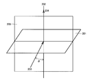
- FIG. 2 shows light incident from the resin base film side (the side opposite to the second fine uneven surface of the hard coat layer) and scattered light in the normal direction of the hard coat layer side (second fine uneven surface side). It is the perspective view which showed typically the incident direction of light when measuring an intensity
- the intensity of the transmitted scattered light 204 transmitted in the direction of the line 202 is measured, and a value obtained by dividing the transmitted scattered light intensity by the light intensity of the light source is defined as a relative scattered light intensity T ( ⁇ ). That is, when the light 203 is incident on the resin base film side of the antiglare film 201 at an angle of 20 ° from the normal line of the antiglare film, the transmitted scattered light 204 observed in the direction of the hard coat layer side normal line 202 is observed.
- the value obtained by dividing the intensity of light by the light intensity of the light source is T (20), and light 203 is incident on the resin base film side of the antiglare film 201 at an angle of 30 ° from the normal line 202 of the antiglare film.
- a value obtained by dividing the intensity of the transmitted scattered light 204 observed in the direction of the hard coat layer side normal 202 by the light intensity of the light source is T (30).
- the light 203 is incident such that the direction of the light 203 incident from the resin base film side and the normal line 202 of the antiglare film are on the same plane (plane 209 in FIG. 2).
- the relative scattered light intensity T (30) at 30 ° incidence is less than 0.00004%, the scattering effect is low, and glare occurs when applied to a high-definition image display device.
- the antiglare film is applied to a liquid crystal display that is not self-luminous, the effect of increasing the brightness due to scattering caused by light leakage during black display is large, and therefore the relative scattered light intensities T (20) and T (30) are high. If it exceeds the preferable range, the contrast is remarkably lowered and the visibility is impaired.
- FIG. 3 shows the relative scattered light intensity (logarithmic scale) measured by changing the incident angle ⁇ of light incident from the resin base film side of the antiglare film of the present invention (antiglare film 201 in FIG. 2). It is an example of the graph plotted with respect to angle (phi). Such a graph representing the relationship between the incident angle and the relative scattered light intensity, or the relative scattered light intensity for each incident angle read therefrom may be referred to as a transmission scattering profile. As shown in this graph, the relative scattered light intensity has a peak at an incident angle of 0 °, and the scattered light intensity tends to decrease as the angle from the normal direction of the incident light 203 increases.
- the transmission / scattering profile usually appears symmetrically about the incident angle of 0 °.
- the relative scattered light intensity T (0) at 0 ° incidence shows a peak at about 15%
- the relative scattered light intensity T (20) at 20 ° incidence is about
- the relative scattered light intensity T (30) at 0.0003% and 30 ° incidence is about 0.00006%.
- a detector In measuring the relative scattered light intensity of the antiglare film, it is necessary to accurately measure the relative scattered light intensity of 0.001% or less. Therefore, it is effective to use a detector with a wide dynamic range.
- a detector for example, a commercially available optical power meter can be used, and an aperture is provided in front of the detector of this optical power meter so that the angle at which the antiglare film is viewed is 2 °. Measurements can be made using an angular photometer. Visible light of 380 to 780 nm can be used as incident light, and a collimated light emitted from a light source such as a halogen lamp can be used as a measurement light source, or a parallel light source using a monochromatic light source such as a laser. Higher ones may be used. Moreover, in order to prevent the curvature of a film, it is preferable to use it for a measurement, after bonding to a glass substrate so that an uneven surface may become the surface using an optically transparent adhesive.
- the relative scattered light intensities T (20) and T (30) defined in the present invention are measured as follows.
- the antiglare film is bonded to a glass substrate so that the uneven surface is the surface, and parallel light from a He—Ne laser is irradiated from the direction inclined at a predetermined angle with respect to the film normal on the glass surface side.
- the transmitted scattered light intensity in the normal direction of the antiglare film is measured on the uneven surface (second fine uneven surface) side of the antiglare film.
- “3292 03 optical power sensor” and “3292 optical power meter” manufactured by Yokogawa Electric Corporation are used for both T (20) and T (30).
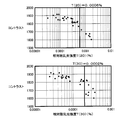
- FIG. 4 is a diagram showing the relationship between the relative scattered light intensities T (20) and T (30) and the contrast.
- T (20) exceeds 0.0006% or T (30) exceeds 0.0002%
- the contrast tends to decrease by 10% or more, and the visibility tends to be impaired.
- the contrast was measured by the following procedure. First, the polarizing plate on the back side and the display surface side is peeled off from a commercially available liquid crystal television (“LC-42GX1W” manufactured by Sharp Corporation). A polarizing plate “Sumikaran SRDB31E” manufactured by Chemical Co., Ltd. was bonded via an adhesive so that each absorption axis coincided with the absorption axis of the original polarizing plate.
- the anti-glare film which has the structure similar to the anti-glare film which concerns on this invention which shows various scattered light intensity
- the liquid crystal television thus obtained was activated in a dark room, and using a luminance meter “BM5A” manufactured by Topcon Corporation, the luminance in the black display state and the white display state was measured, and the contrast was calculated.
- the contrast is represented by the ratio of the luminance in the white display state to the luminance in the black display state.
- the antiglare film of the present invention has a reflectance R (30) at a reflection angle of 30 ° of 0.05% or more and 2% or less when light is incident from the hard coat layer side at an incident angle of 30 °.
- the reflectance R (40) at a reflection angle of 40 ° is 0.0001% or more and 0.005% or less
- the reflectance R (50) at a reflection angle of 50 ° is 0.00001% or more and 0.0005% or less. It is preferable.
- FIG. 5 is a perspective view schematically showing an incident direction and a reflection direction of light from the hard coat layer side with respect to the antiglare film when the reflectance is obtained.
- the direction of the reflection angle of 30 ° that is, the regular reflection direction with respect to the light 505 incident at an angle of 30 ° from the normal line 502 of the antiglare film on the hard coat layer side of the antiglare film 501.
- the reflectance (that is, regular reflectance) of the reflected light to 506 is R (30).
- the direction of reflected light when measuring the reflectance is within the plane 509 including the direction of the incident light 505 and the normal line 502. To do.
- the regular reflectance R (30) exceeds 2%, a sufficient antiglare function cannot be obtained, and the visibility tends to decrease. On the other hand, even if the regular reflectance R (30) is too small, it tends to cause whitening. Therefore, the regular reflectance R (30) is preferably 0.05% or more. The regular reflectance R (30) is more preferably 1.5% or less, particularly 0.7% or less. On the other hand, if R (40) exceeds 0.005% or R (50) exceeds 0.0005%, the antiglare film is whitened and the visibility tends to be lowered.
- R (40) and R (50) are not so large.
- R (40) is generally preferably 0.0001% or more
- R (50) is generally 0, since sufficient antiglare properties are not exhibited even if the reflectance at these angles is too small. It is preferably 0.0001% or more.
- R (50) is more preferably 0.0001% or less.
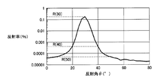
- FIG. 6 shows the reflection of the light 507 reflected at the reflection angle ⁇ with respect to the light 505 incident at an angle of 30 ° from the normal 502 on the hard coat layer side of the antiglare film of the present invention (antiglare film 501 in FIG. 5).
- a reflectance is a logarithmic scale.
- Such a graph representing the relationship between the reflection angle and the reflectance, or the reflectance for each reflection angle read therefrom may be referred to as a reflection profile.
- the regular reflectance R (30) is a reflectance peak with respect to the light 505 incident at 30 °, and the reflectance tends to decrease as the angle deviates from the regular reflection direction.
- the regular reflectance R (30) is about 0.2%
- R (40) is about 0.0004%
- R (50) is about 0.00004%. .
- a detector In measuring the reflectance of the antiglare film, it is necessary to accurately measure a reflectance of 0.001% or less, as with the relative scattered light intensity. Therefore, it is effective to use a detector with a wide dynamic range.
- a detector for example, a commercially available optical power meter can be used, and an aperture is provided in front of the detector of this optical power meter so that the angle at which the antiglare film is viewed is 2 °. Measurements can be made using an angular photometer.
- incident light visible light of 380 to 780 nm can be used, and as a measurement light source, collimated light emitted from a light source such as a halogen lamp can be used, or in parallel with a monochromatic light source such as a laser.
- a high degree may be used.
- reflection from the back surface of the antiglare film may affect the measured value.
- the smooth surface of the antiglare film is adhered to a black acrylic resin plate with an adhesive or It is preferable that only the reflectance of the outermost surface of the antiglare film (second fine uneven surface) can be measured by optical adhesion using a liquid such as water or glycerin.
- the reflectances R (30), R (40) and R (50) defined in the present invention are measured as follows.
- the parallel surface from the He-Ne laser is irradiated onto the uneven surface (second fine uneven surface) of the anti-glare film from a direction inclined by 30 ° with respect to the film normal, and the normal and light incidence of the anti-glare film are incident.
- the angle change of the reflectance in the plane including the direction is measured.
- both “3292 03 Optical Power Sensor” and “3292 Optical Power Meter” manufactured by Yokogawa Electric Corporation are used.
- the antiglare film of the present invention may have a low reflection film on the outermost surface, that is, the second fine uneven surface of the hard coat layer. Even in the absence of a low reflection film, a sufficient antiglare function is exhibited, but the antiglare property can be further improved by providing a low reflection film on the outermost surface.
- the low reflection film can be formed by providing a layer made of a low refractive index material having a refractive index lower than that of the hard coat layer on the hard coat layer. Specific examples of such a low refractive index material include lithium fluoride (LiF), magnesium fluoride (MgF 2 ), aluminum fluoride (AlF 3 ), cryolite (3NaF ⁇ AlF 3 or Na 3 AlF 6).
- inorganic low-reflective materials containing acrylic resin, epoxy resin, etc .; fluorine-based or silicone-based organic compounds, thermoplastic resins, thermosetting resins, UV-curable resins, etc.
- An organic low reflection material can be mentioned.
- the antiglare film of the present invention is excellent in the antiglare effect, effectively prevents whitening, and can effectively suppress the occurrence of glare and the decrease in contrast.
- An image display device provided with such an antiglare film of the present invention has excellent visibility.
- the polarizing plate generally has a form in which a protective film is bonded to at least one surface of a polarizing film made of a polyvinyl alcohol-based resin film in which iodine or a dichroic dye is adsorbed and oriented.
- an antiglare polarizing plate can be obtained by laminating the polarizing film and the antiglare film of the present invention on the resin base film side of the antiglare film.
- the other surface of the polarizing film may be in a state where nothing is laminated, another protective film or an optical film may be laminated, or an adhesive layer for bonding to a liquid crystal cell. May be formed.
- the antiglare film of the present invention is bonded on the side of the resin substrate film on the protective film of the polarizing plate having a protective film bonded to at least one surface of the polarizing film to obtain an antiglare polarizing plate.
- the resin base film is used as the protective film, and the hard coat layer is formed on the resin base film, thereby providing an antiglare polarizing plate. It can also be.
- the image display device of the present invention is a combination of the antiglare film or the antiglare polarizing plate of the present invention and an image display element.
- the image display element is typically a liquid crystal panel that includes a liquid crystal cell in which liquid crystal is sealed between upper and lower substrates and displays an image by changing the alignment state of the liquid crystal by applying a voltage.
- the antiglare film or the antiglare polarizing plate of the present invention can be applied to various known displays such as a display, a CRT display, and an organic EL display.
- the antiglare film is disposed on the viewing side with respect to the image display element.
- the antiglare film may be directly bonded to the surface of the image display element.
- the image display device provided with the antiglare film of the present invention can scatter incident light due to the unevenness of the surface of the antiglare film and blur the reflected image, and has excellent visibility in the image display device. give.
- the anti-glare film of the present invention does not cause glare as seen in conventional anti-glare films even when applied to a high-definition image display device. Prevention performance, glare suppression, and contrast reduction suppression performance.
- the surface shapes of the first fine uneven surface of the resin substrate film and the second fine uneven surface of the antiglare film were measured by the following method. That is, after bonding the resin substrate film or the antiglare film to the glass substrate using an optically transparent adhesive so that the first fine uneven surface or the second fine uneven surface becomes the surface, Three-dimensional information of the surface shape was obtained using a confocal microscope “PL ⁇ 2300” manufactured by Sensofar. In the measurement, three or more areas of 200 ⁇ m ⁇ 200 ⁇ m or more were performed, and the average value was used as the measurement value. At the time of measurement, the magnification of the objective lens was 50 times.
- the arithmetic average heights Pa 1 and Pa 2 , the maximum cross-sectional heights Pt 1 and Pt 2 , and the average lengths PSm 1 and Psm in the cross-section curve are calculated according to JIS B 0601. 2 was sought.
- the thickness of the resin base film is an average value of the distance from the convex portion of the first fine uneven surface to the bottom surface of the transparent resin layer of the lowest layer, It measured using the Nikon contact-type film thickness meter "DEGIMICRO MS 5C".
- the thickness of the antiglare film is an average value of the distance from the convex portion of the second fine uneven surface to the bottom surface of the lowermost transparent resin layer, and was measured using the same apparatus.
- the thickness of the hard coat layer was determined as the difference between the thickness of the antiglare film and the thickness of the resin base film.
- the internal haze of the resin base film was measured as follows. First, the resin substrate film is bonded to a glass substrate using an optically transparent adhesive so that the surface opposite to the first fine uneven surface is on the glass substrate side, A triacetyl cellulose film (TAC film) having a haze of approximately 0% was bonded onto the fine irregular surface of 1 using glycerin. With respect to the resin base film to which this TAC film is bonded, the haze value measured using a haze meter “HM-150” manufactured by Murakami Color Research Laboratory Co., Ltd. based on JIS K 7136 is used as the resin base film. The internal haze of the film was used.
- TAC film triacetyl cellulose film
- the surface haze and internal haze of the hard coat layer were measured as follows. First, after forming a hard coat layer on a resin base film to produce an anti-glare film, the anti-glare film and the glass substrate are pasted using a transparent adhesive so that the resin base film side becomes the bonding surface. The haze measured according to JIS K 7136 was defined as the “overall haze” of the antiglare film. Next, a triacetyl cellulose film having a haze of approximately 0 is bonded to the second fine uneven surface of the hard coat layer using glycerin, and the haze measured according to JIS K 7136 is applied to the antiglare film. "Internal haze”. Based on the above formulas (1) and (2), the surface haze and internal haze of the hard coat layer were calculated from the obtained haze value and internal haze of the resin base film.
- the antiglare film is bonded to a glass substrate so that the uneven surface thereof is the surface, and from the direction inclined at a predetermined angle with respect to the normal line of the antiglare film on the glass surface side, He Parallel light from a -Ne laser was irradiated, and the transmitted scattered light intensity in the normal direction of the antiglare film was measured on the uneven surface side of the antiglare film.
- transmitted scattered light intensity “3292 03 Optical Power Sensor” and “3292 Optical Power Meter” manufactured by Yokogawa Electric Corporation were used.
- the transmission clarity of the antiglare film was measured using an image clarity measuring device “ICM-1DP” manufactured by Suga Test Instruments Co., Ltd. in accordance with JIS K 7105. Also in this case, in order to prevent the sample from warping, it was subjected to measurement after being bonded to a glass substrate using an optically transparent adhesive so that the concavo-convex surface became the surface. In this state, light was incident from the glass side and measurement was performed.
- the measured value here is a total value of values measured using four types of optical combs in which the widths of the dark part and the bright part are 0.125 mm, 0.5 mm, 1.0 mm, and 2.0 mm, respectively. . In this case, the maximum value of the transmission clarity is 400%.
- a photomask having a unit cell pattern as shown in a plan view in FIG. 7 was prepared.
- a key-shaped chrome light shielding pattern 701 having a line width of 10 ⁇ m is formed on a transparent substrate, and a portion where the chrome light shielding pattern 701 is not formed is an opening 702.
- the unit cell 700 has a size of 254 ⁇ m ⁇ 84 ⁇ m (vertical ⁇ horizontal in the drawing), and thus the size of the opening 702 is 244 ⁇ m ⁇ 74 ⁇ m (vertical ⁇ horizontal in the drawing).
- a large number of unit cells 700 shown in the figure are arranged vertically and horizontally to form a photomask.
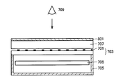
- the chrome light-shielding pattern 701 of the photomask 703 is placed on the light box 705, and the antiglare film 801 is coated with the adhesive on the glass plate 707 with the uneven surface on the surface.
- the sample bonded so as to become is placed on the photomask 703.
- a light source 706 is disposed in the light box 705. In this state, visual observation was performed at a position 709 that is about 30 cm away from the sample. The degree of glare was evaluated according to the following criteria in three stages of 1 to 3. Glitter; 1: Glitter is not recognized. 2: Very slight glare is observed. 3: Severe glare is observed.
- a resin base film having a two-layer structure with a thickness of 80 ⁇ m was produced through a roll unit set at 85 ° C.
- Pentaerythritol triacrylate 60 parts Polyfunctional urethanized acrylate (reaction product of hexamethylene diisocyanate and pentaerythritol triacrylate) 40 parts Next, 100 parts by weight of the solid content of the ultraviolet curable resin composition is subjected to photopolymerization. A coating solution was prepared by adding 5 parts by weight of “Lucillin TPO” (manufactured by BASF, chemical name: 2,4,6-trimethylbenzoyldiphenylphosphine oxide) as an initiator.
- “Lucillin TPO” manufactured by BASF, chemical name: 2,4,6-trimethylbenzoyldiphenylphosphine oxide
- This coating solution was applied to the surface of the light diffusion layer of the resin substrate film with No. It was applied at a coating speed of 2.0 mm / sec with a bar coater using a 2-wire bar, and dried for 1 minute in a dryer set at 80 ° C.
- a fusion “D bulb” lamp maximum emission wavelength 380 nm
- the integrated light quantity becomes 1720 mJ / cm 2 at an illuminance of 985 mW / cm 2.
- a UV curable resin composition layer is cured to form a laminate of a hard coat layer (cured resin layer) having a second fine irregular surface and a thickness of 2.4 ⁇ m and a resin base film. An antiglare film was obtained.
- Example 2 Lamination of a hard coat layer having a thickness of 6.1 ⁇ m and a resin base film in the same manner as in Example 1 except that the coating liquid coating conditions for forming the hard coat layer were changed as shown in Table 1. An antiglare film consisting of a body was produced.
- Example 3 Except that the addition amount of methyl methacrylate / styrene copolymer resin particles dispersed in the light diffusion layer of the resin base film and the coating liquid coating conditions when forming the hard coat layer are changed as shown in Table 1. Produced an antiglare film comprising a laminate of a hard coat layer having a thickness of 1.6 ⁇ m and a resin base film in the same manner as in Example 1.
- Example 4 Lamination of a hard coat layer having a thickness of 3.8 ⁇ m and a resin base film in the same manner as in Example 3 except that the coating liquid coating conditions for forming the hard coat layer were changed as shown in Table 1. An antiglare film consisting of a body was produced.
- Example 5 Particle size of methyl methacrylate / styrene copolymer resin particles dispersed in the light diffusing layer of the resin base film (meaning weight average particle size; the same applies hereinafter) and coating liquid application when forming a hard coat layer
- An antiglare film made of a laminate of a hard coat layer having a thickness of 1.6 ⁇ m and a resin substrate film was produced in the same manner as in Example 1 except that the conditions were changed as shown in Table 1.
- Example 6> The particle diameter and addition amount of methyl methacrylate / styrene copolymer resin particles dispersed in the light diffusion layer of the resin base film and the coating liquid coating conditions when forming the hard coat layer were changed as shown in Table 1. Except for this, an antiglare film comprising a laminate of a hard coat layer having a thickness of 1.8 ⁇ m and a resin base film was produced in the same manner as in Example 1.
- the resin base film has a three-layer structure of transparent resin layer (thickness 25 ⁇ m) / light diffusion layer (thickness 30 ⁇ m) / transparent resin layer (thickness 25 ⁇ m), and coating liquid coating when forming a hard coat layer
- An antiglare film comprising a laminate of a hard coat layer having a thickness of 1.3 ⁇ m and a resin base film was produced in the same manner as in Example 1 except that the conditions were changed as shown in Table 1.
- Table 1 shows the refractive index and particle size of the methyl methacrylate / styrene copolymer resin beads dispersed in the light diffusion layer of the resin base film, and the coating liquid coating conditions for forming the hard coat layer. Except having changed, it carried out similarly to Example 1, and produced the glare-proof film which consists of a laminated body of the hard-coat layer and resin base film whose thickness is shown in Table 1.
- Table 1 shows the particle diameter of the methyl methacrylate / styrene copolymer resin beads dispersed in the light diffusion layer of the resin base film (only Comparative Example 5) and the coating liquid coating conditions for forming the hard coat layer.
- An antiglare film composed of a laminate of a hard coat layer and a resin base film having a thickness as shown in Table 1 was produced in the same manner as in Example 1 except that the thickness was changed as described above.
- FIG. 9 shows the angle dependence of the scattered light intensity obtained by measuring the scattered light intensity for the antiglare films of Examples 1 to 6 (graph of the transmission scattering profile).
- FIG. 9 shows the angle dependence of the reflected light obtained by the reflectance measurement.
- FIG. 10 shows the property (graph of reflection profile).
- FIGS. 11 and 12 are a graph of a transmission / scattering profile and a graph of a reflection profile for the antiglare films of Comparative Examples 1 to 3, respectively.
- 13 and 14 are a graph of a transmission / scattering profile and a graph of a reflection profile for the antiglare films of Comparative Examples 4 and 5, respectively.
- the anti-glare films of Examples 1 to 6 show excellent anti-glare performance, do not cause glare and whitish, and do not reduce contrast when applied to an image display device.
- the causal relative scattered light intensities T (20) and T (30) also showed good scattering characteristics sufficiently low.
- the antiglare film of Comparative Example 1 since the antiglare film of Comparative Example 1 has a small arithmetic average height Pa 1 of the first fine uneven surface of the resin base film, the arithmetic average height of the second fine uneven surface of the hard coat layer is low. It was too small Pa 2 , and sufficient antiglare property could not be obtained.
- the arithmetic average height Pa 1 of the first fine uneven surface of the resin base film is large, and the thickness of the hard coat layer is 1.8 ⁇ m.
- the arithmetic average height Pa 2 of the second fine uneven surface is increased, the whitish occurs and the hard coat layer has a thickness of 6.8 ⁇ m. Since the average length PSm 2 of the fine uneven surface 2 was increased, the image was reflected and the texture was remarkably deteriorated.
- the anti-glare film of Comparative Example 4 uses the same resin base film as in Example 1, the thickness of the hard coat layer was small, so that the effect of smoothing the first fine uneven surface of the resin base film was achieved. As a result, the arithmetic average height Pa 2 of the second fine concavo-convex shape of the obtained antiglare film was increased, and whitening occurred.
- the anti-glare film of the comparative example 5 uses the resin base film similar to Example 5, since the thickness of the hard-coat layer was large, the arithmetic mean height Pa2 of the 2nd fine unevenness
- the results of Examples 1 and 5 and Comparative Examples 4 and 5 show that the first fine uneven surface having an appropriate surface shape was formed, and hard coat layer formation conditions (for example, the composition of the coating solution and the coating solution) It is shown that an antiglare film having excellent reflection characteristics and good antiglare performance can be obtained by controlling the coating conditions and the like to form the second fine uneven surface having an appropriate surface shape. .
- the antiglare film of the present invention By arranging the antiglare film of the present invention on the viewer side from the image display element to constitute an image display device, whitening and in various displays such as a liquid crystal display, a plasma display, a CRT display, an organic EL display, etc.
- a liquid crystal display a plasma display
- a CRT display a CRT display
- an organic EL display etc.
- the occurrence of glare can be prevented, the reflected image can be blurred, and excellent visibility can be obtained.
Landscapes
- Physics & Mathematics (AREA)
- General Physics & Mathematics (AREA)
- Optics & Photonics (AREA)
- Engineering & Computer Science (AREA)
- Manufacturing & Machinery (AREA)
- Chemical & Material Sciences (AREA)
- Dispersion Chemistry (AREA)
- Polarising Elements (AREA)
- Optical Elements Other Than Lenses (AREA)
- Liquid Crystal (AREA)
- Laminated Bodies (AREA)
- Surface Treatment Of Optical Elements (AREA)
Abstract
L'invention porte sur un film antireflet qui comporte un film de base en résine (101a, 101b) et une couche de revêtement dure (102a, 102b), le film de base en résine (101a, 101b) comportant une couche de résine transparente (104a, 104b) et une couche de diffusion de lumière (103a, 103b) contenant des microparticules (105a, 105b), et ayant une première surface finement irrégulière (110a, 110b), la couche de revêtement dure (102a, 102b) étant stratifiée sur la surface du film de base en résine (101a, 101b) et ayant une seconde surface finement irrégulière (120a, 120b). L'invention porte également sur une plaque de polarisation antireflet et sur un dispositif d'affichage d'image ayant chacun le film antireflet. La première surface finement irrégulière (110a, 110b) présente une hauteur de moyenne arithmétique Pa1 de 0,4 à 2 µm et une longueur moyenne PSm1 de 2 à 40 µm, et la seconde surface finement irrégulière (120a, 120b) présente une hauteur de moyenne arithmétique Pa2 de 0,2 à 0,6 µm et une longueur moyenne PSm2 de 20 à 100 µm, à la condition que Pa1 et Pa2 satisfassent à l'exigence exprimée par la formule suivante : Pa2 < Pa1.
Applications Claiming Priority (2)
| Application Number | Priority Date | Filing Date | Title |
|---|---|---|---|
| JP2008-046395 | 2008-02-27 | ||
| JP2008046395A JP2009204837A (ja) | 2008-02-27 | 2008-02-27 | 防眩フィルム、防眩性偏光板および画像表示装置 |
Publications (1)
| Publication Number | Publication Date |
|---|---|
| WO2009107536A1 true WO2009107536A1 (fr) | 2009-09-03 |
Family
ID=41015936
Family Applications (1)
| Application Number | Title | Priority Date | Filing Date |
|---|---|---|---|
| PCT/JP2009/052868 Ceased WO2009107536A1 (fr) | 2008-02-27 | 2009-02-19 | Film antireflet, plaque de polarisation antireflet et dispositif d'affichage d'image |
Country Status (3)
| Country | Link |
|---|---|
| JP (1) | JP2009204837A (fr) |
| TW (1) | TW200951503A (fr) |
| WO (1) | WO2009107536A1 (fr) |
Cited By (12)
| Publication number | Priority date | Publication date | Assignee | Title |
|---|---|---|---|---|
| JP2012133078A (ja) * | 2010-12-21 | 2012-07-12 | Konica Minolta Advanced Layers Inc | 反射防止フィルム、その製造方法、偏光板、及び画像表示装置 |
| EP3299851A4 (fr) * | 2015-09-11 | 2018-08-08 | LG Chem, Ltd. | Film anti-reflet et dispositif d'affichage |
| WO2020176465A1 (fr) * | 2019-02-25 | 2020-09-03 | Visteon Global Technologies, Inc. | Système et procédé pour régler l'intensité de lumière dans un système d'affichage |
| US20220268974A1 (en) * | 2019-02-25 | 2022-08-25 | Visteon Global Technologies, Inc. | System and method for adjusting light intensity in a display system |
| CN116133998A (zh) * | 2020-07-09 | 2023-05-16 | 康宁公司 | 具有绕射防眩表面的显示器制品及其制造方法 |
| US11699403B2 (en) | 2019-02-25 | 2023-07-11 | Visteon Global Technologies, Inc. | Display system |
| US11698554B2 (en) | 2019-02-25 | 2023-07-11 | Visteon Global Technologies, Inc. | Display system |
| US11747672B2 (en) | 2019-02-25 | 2023-09-05 | Visteon Global Technologies, Inc. | System and method for adjusting light intensity in a display system |
| US11782309B2 (en) | 2019-02-25 | 2023-10-10 | Visteon Global Technologies, Inc. | Display system |
| US20240069254A1 (en) * | 2019-02-25 | 2024-02-29 | Visteon Global Technologies, Inc. | System and method for adjusting light intensity in a display system |
| US11953778B2 (en) | 2019-02-25 | 2024-04-09 | Visteon Global Technologies, Inc. | System and method for adjusting light intensity in a display system |
| US12197069B1 (en) | 2023-09-05 | 2025-01-14 | Visteon Global Technologies, Inc. | System and method for adjusting light intensity in a display system |
Families Citing this family (9)
| Publication number | Priority date | Publication date | Assignee | Title |
|---|---|---|---|---|
| JP5801062B2 (ja) * | 2010-03-11 | 2015-10-28 | 住友化学株式会社 | 防眩フィルムおよび防眩性偏光板 |
| JP2011221197A (ja) * | 2010-04-08 | 2011-11-04 | Suntechopt Co Ltd | アンチグレア拡散フィルム |
| KR20130045267A (ko) * | 2010-06-02 | 2013-05-03 | 키모토 컴파니 리미티드 | 유기 el용 산란 필름 및 그것을 사용한 유기 el 발광장치 |
| JP2012078736A (ja) * | 2010-10-06 | 2012-04-19 | Sumitomo Chemical Co Ltd | 光拡散フィルムおよびその製造方法、光拡散性偏光板、ならびに液晶表示装置 |
| WO2012067046A1 (fr) * | 2010-11-16 | 2012-05-24 | 住友化学株式会社 | Film de dispersion de la lumière, plaque de polarisation et dispositif d'affichage d'image |
| JP2013145833A (ja) * | 2012-01-16 | 2013-07-25 | Fujifilm Corp | Led発光素子用反射基板およびledパッケージ |
| KR101597482B1 (ko) * | 2012-01-17 | 2016-02-24 | 미쓰비시 쥬시 가부시끼가이샤 | 반사재 |
| CN105612438B (zh) * | 2013-10-02 | 2018-12-14 | 3M创新有限公司 | 包括第一微结构化层和涂层的微结构化漫射体、光学叠堆以及方法 |
| JP7535035B2 (ja) * | 2019-04-03 | 2024-08-15 | 日東電工株式会社 | 光拡散フィルム、光拡散フィルムの製造方法、光学部材、画像表示装置用表示パネルおよび画像表示装置 |
Citations (3)
| Publication number | Priority date | Publication date | Assignee | Title |
|---|---|---|---|---|
| JP2004069867A (ja) * | 2002-08-05 | 2004-03-04 | Dainippon Printing Co Ltd | 低反射フィルム |
| JP2005258155A (ja) * | 2004-03-12 | 2005-09-22 | Dainippon Printing Co Ltd | 透過型スクリーン用光拡散部材 |
| JP2007293303A (ja) * | 2006-03-28 | 2007-11-08 | Fujifilm Corp | 光散乱フィルム、偏光板、及び画像表示装置 |
-
2008
- 2008-02-27 JP JP2008046395A patent/JP2009204837A/ja not_active Withdrawn
-
2009
- 2009-02-19 WO PCT/JP2009/052868 patent/WO2009107536A1/fr not_active Ceased
- 2009-02-25 TW TW098105996A patent/TW200951503A/zh unknown
Patent Citations (3)
| Publication number | Priority date | Publication date | Assignee | Title |
|---|---|---|---|---|
| JP2004069867A (ja) * | 2002-08-05 | 2004-03-04 | Dainippon Printing Co Ltd | 低反射フィルム |
| JP2005258155A (ja) * | 2004-03-12 | 2005-09-22 | Dainippon Printing Co Ltd | 透過型スクリーン用光拡散部材 |
| JP2007293303A (ja) * | 2006-03-28 | 2007-11-08 | Fujifilm Corp | 光散乱フィルム、偏光板、及び画像表示装置 |
Cited By (18)
| Publication number | Priority date | Publication date | Assignee | Title |
|---|---|---|---|---|
| JP2012133078A (ja) * | 2010-12-21 | 2012-07-12 | Konica Minolta Advanced Layers Inc | 反射防止フィルム、その製造方法、偏光板、及び画像表示装置 |
| EP3299851A4 (fr) * | 2015-09-11 | 2018-08-08 | LG Chem, Ltd. | Film anti-reflet et dispositif d'affichage |
| US10690810B2 (en) | 2015-09-11 | 2020-06-23 | Lg Chem Ltd. | Antireflection film and display device having hard coating layer with specified surface roughness and internal haze |
| US11698554B2 (en) | 2019-02-25 | 2023-07-11 | Visteon Global Technologies, Inc. | Display system |
| US11782309B2 (en) | 2019-02-25 | 2023-10-10 | Visteon Global Technologies, Inc. | Display system |
| US11953778B2 (en) | 2019-02-25 | 2024-04-09 | Visteon Global Technologies, Inc. | System and method for adjusting light intensity in a display system |
| US20240069254A1 (en) * | 2019-02-25 | 2024-02-29 | Visteon Global Technologies, Inc. | System and method for adjusting light intensity in a display system |
| US11699403B2 (en) | 2019-02-25 | 2023-07-11 | Visteon Global Technologies, Inc. | Display system |
| WO2020176465A1 (fr) * | 2019-02-25 | 2020-09-03 | Visteon Global Technologies, Inc. | Système et procédé pour régler l'intensité de lumière dans un système d'affichage |
| US11747672B2 (en) | 2019-02-25 | 2023-09-05 | Visteon Global Technologies, Inc. | System and method for adjusting light intensity in a display system |
| US20220268974A1 (en) * | 2019-02-25 | 2022-08-25 | Visteon Global Technologies, Inc. | System and method for adjusting light intensity in a display system |
| US11808957B2 (en) | 2019-02-25 | 2023-11-07 | Visteon Global Technologies, Inc. | System and method for adjusting light intensity in a display system |
| CN116157369A (zh) * | 2020-07-09 | 2023-05-23 | 康宁公司 | 具防眩表面及薄的耐用抗反射涂层的显示器制品 |
| CN116133998A (zh) * | 2020-07-09 | 2023-05-16 | 康宁公司 | 具有绕射防眩表面的显示器制品及其制造方法 |
| US12352924B2 (en) | 2020-07-09 | 2025-07-08 | Corning Incorporated | Display articles with diffractive, antiglare surfaces and methods of making the same |
| US12386101B2 (en) | 2020-07-09 | 2025-08-12 | Corning Incorporated | Textured region of a substrate to reduce specular reflectance incorporating surface features with an elliptical perimeter or segments thereof, and method of making the same |
| CN116133998B (zh) * | 2020-07-09 | 2026-01-09 | 康宁公司 | 具有绕射防眩表面的显示器制品及其制造方法 |
| US12197069B1 (en) | 2023-09-05 | 2025-01-14 | Visteon Global Technologies, Inc. | System and method for adjusting light intensity in a display system |
Also Published As
| Publication number | Publication date |
|---|---|
| TW200951503A (en) | 2009-12-16 |
| JP2009204837A (ja) | 2009-09-10 |
Similar Documents
| Publication | Publication Date | Title |
|---|---|---|
| WO2009107536A1 (fr) | Film antireflet, plaque de polarisation antireflet et dispositif d'affichage d'image | |
| CN101836136B (zh) | 防眩膜、防眩性偏振板及图像显示装置 | |
| KR101751192B1 (ko) | 방현 필름, 편광판, 액정 패널 및 화상 표시 장치 | |
| CN107718800B (zh) | 防眩性膜、偏振片和图像显示装置 | |
| JP2009150998A (ja) | 防眩フィルム、防眩性偏光板および画像表示装置 | |
| TWI480570B (zh) | 防眩性硬塗薄膜、使用其之偏光板及影像顯示裝置、以及防眩性硬塗薄膜之製造方法 | |
| US20110080643A1 (en) | Hard-coated antiglare film, polarizing plate and image display including the same, and method for evaluating the same | |
| JP6647761B2 (ja) | 上用光拡散シート及びバックライトユニット | |
| JP2009169409A (ja) | 防眩フィルム、防眩性偏光板および画像表示装置 | |
| TWI454725B (zh) | 光學積層膜 | |
| JP2009156938A (ja) | 防眩フィルム、防眩性偏光板および画像表示装置 | |
| JP2006116754A (ja) | 減反射材及びそれを用いた電子画像表示装置 | |
| JP2009156939A (ja) | 防眩フィルム、防眩性偏光板および画像表示装置 | |
| US20110080644A1 (en) | Hard-coated antiglare film, polarizing plate and image display including the same, method for producing the same, and method for evaluating the same | |
| JP2010102072A (ja) | 防眩フィルム、防眩性偏光板および画像表示装置 | |
| KR20190053920A (ko) | 눈부심 방지성 반사 방지 하드 코팅 필름, 화상 표시 장치, 눈부심 방지성 반사 방지 하드 코팅 필름 제조 방법 | |
| KR20170018327A (ko) | 광확산성 시트 및 그 시트를 포함하는 백라이트 장치 | |
| JP2010102186A (ja) | 防眩フィルム、防眩性偏光板および画像表示装置 | |
| JP5102958B2 (ja) | 反射防止フィルムの製造方法 | |
| WO2009104480A1 (fr) | Film de résine stratifié diffusant la lumière, son procédé de fabrication, film antireflet, polariseur antireflet et dispositif d'affichage d'image | |
| JP2022082580A (ja) | 偏光板および画像表示装置 | |
| JP2009122645A (ja) | 防眩フィルム、防眩性偏光板および画像表示装置 | |
| US8778489B2 (en) | Optical layered product | |
| JP2009048092A (ja) | 光学積層体 | |
| JP2009103734A (ja) | 防眩性フィルム、偏光板、および画像表示装置 |
Legal Events
| Date | Code | Title | Description |
|---|---|---|---|
| 121 | Ep: the epo has been informed by wipo that ep was designated in this application |
Ref document number: 09714376 Country of ref document: EP Kind code of ref document: A1 |
|
| NENP | Non-entry into the national phase |
Ref country code: DE |
|
| 122 | Ep: pct application non-entry in european phase |
Ref document number: 09714376 Country of ref document: EP Kind code of ref document: A1 |