WO2009110080A1 - Unité de feu arrière - Google Patents
Unité de feu arrière Download PDFInfo
- Publication number
- WO2009110080A1 WO2009110080A1 PCT/JP2008/054024 JP2008054024W WO2009110080A1 WO 2009110080 A1 WO2009110080 A1 WO 2009110080A1 JP 2008054024 W JP2008054024 W JP 2008054024W WO 2009110080 A1 WO2009110080 A1 WO 2009110080A1
- Authority
- WO
- WIPO (PCT)
- Prior art keywords
- reflector
- led
- substrate
- taillight
- lens
- Prior art date
- Legal status (The legal status is an assumption and is not a legal conclusion. Google has not performed a legal analysis and makes no representation as to the accuracy of the status listed.)
- Ceased
Links
Images




Classifications
-
- B—PERFORMING OPERATIONS; TRANSPORTING
- B60—VEHICLES IN GENERAL
- B60Q—ARRANGEMENT OF SIGNALLING OR LIGHTING DEVICES, THE MOUNTING OR SUPPORTING THEREOF OR CIRCUITS THEREFOR, FOR VEHICLES IN GENERAL
- B60Q1/00—Arrangement of optical signalling or lighting devices, the mounting or supporting thereof or circuits therefor
- B60Q1/0029—Spatial arrangement
- B60Q1/0041—Spatial arrangement of several lamps in relation to each other
- B60Q1/0058—Stacked, i.e. one lamp located behind the other in the optical axis direction
-
- B—PERFORMING OPERATIONS; TRANSPORTING
- B60—VEHICLES IN GENERAL
- B60Q—ARRANGEMENT OF SIGNALLING OR LIGHTING DEVICES, THE MOUNTING OR SUPPORTING THEREOF OR CIRCUITS THEREFOR, FOR VEHICLES IN GENERAL
- B60Q1/00—Arrangement of optical signalling or lighting devices, the mounting or supporting thereof or circuits therefor
- B60Q1/26—Arrangement of optical signalling or lighting devices, the mounting or supporting thereof or circuits therefor the devices being primarily intended to indicate the vehicle, or parts thereof, or to give signals, to other traffic
- B60Q1/2607—Arrangement of optical signalling or lighting devices, the mounting or supporting thereof or circuits therefor the devices being primarily intended to indicate the vehicle, or parts thereof, or to give signals, to other traffic comprising at least two indicating lamps
-
- B—PERFORMING OPERATIONS; TRANSPORTING
- B60—VEHICLES IN GENERAL
- B60Q—ARRANGEMENT OF SIGNALLING OR LIGHTING DEVICES, THE MOUNTING OR SUPPORTING THEREOF OR CIRCUITS THEREFOR, FOR VEHICLES IN GENERAL
- B60Q1/00—Arrangement of optical signalling or lighting devices, the mounting or supporting thereof or circuits therefor
- B60Q1/26—Arrangement of optical signalling or lighting devices, the mounting or supporting thereof or circuits therefor the devices being primarily intended to indicate the vehicle, or parts thereof, or to give signals, to other traffic
- B60Q1/2696—Mounting of devices using LEDs
-
- B—PERFORMING OPERATIONS; TRANSPORTING
- B62—LAND VEHICLES FOR TRAVELLING OTHERWISE THAN ON RAILS
- B62J—CYCLE SADDLES OR SEATS; AUXILIARY DEVICES OR ACCESSORIES SPECIALLY ADAPTED TO CYCLES AND NOT OTHERWISE PROVIDED FOR, e.g. ARTICLE CARRIERS OR CYCLE PROTECTORS
- B62J6/00—Arrangement of optical signalling or lighting devices on cycles; Mounting or supporting thereof; Circuits therefor
- B62J6/04—Rear lights
- B62J6/045—Rear lights indicating braking
-
- F—MECHANICAL ENGINEERING; LIGHTING; HEATING; WEAPONS; BLASTING
- F21—LIGHTING
- F21S—NON-PORTABLE LIGHTING DEVICES; SYSTEMS THEREOF; VEHICLE LIGHTING DEVICES SPECIALLY ADAPTED FOR VEHICLE EXTERIORS
- F21S43/00—Signalling devices specially adapted for vehicle exteriors, e.g. brake lamps, direction indicator lights or reversing lights
- F21S43/10—Signalling devices specially adapted for vehicle exteriors, e.g. brake lamps, direction indicator lights or reversing lights characterised by the light source
- F21S43/13—Signalling devices specially adapted for vehicle exteriors, e.g. brake lamps, direction indicator lights or reversing lights characterised by the light source characterised by the type of light source
- F21S43/14—Light emitting diodes [LED]
-
- F—MECHANICAL ENGINEERING; LIGHTING; HEATING; WEAPONS; BLASTING
- F21—LIGHTING
- F21S—NON-PORTABLE LIGHTING DEVICES; SYSTEMS THEREOF; VEHICLE LIGHTING DEVICES SPECIALLY ADAPTED FOR VEHICLE EXTERIORS
- F21S43/00—Signalling devices specially adapted for vehicle exteriors, e.g. brake lamps, direction indicator lights or reversing lights
- F21S43/10—Signalling devices specially adapted for vehicle exteriors, e.g. brake lamps, direction indicator lights or reversing lights characterised by the light source
- F21S43/19—Attachment of light sources or lamp holders
-
- F—MECHANICAL ENGINEERING; LIGHTING; HEATING; WEAPONS; BLASTING
- F21—LIGHTING
- F21S—NON-PORTABLE LIGHTING DEVICES; SYSTEMS THEREOF; VEHICLE LIGHTING DEVICES SPECIALLY ADAPTED FOR VEHICLE EXTERIORS
- F21S43/00—Signalling devices specially adapted for vehicle exteriors, e.g. brake lamps, direction indicator lights or reversing lights
- F21S43/30—Signalling devices specially adapted for vehicle exteriors, e.g. brake lamps, direction indicator lights or reversing lights characterised by reflectors
-
- F—MECHANICAL ENGINEERING; LIGHTING; HEATING; WEAPONS; BLASTING
- F21—LIGHTING
- F21S—NON-PORTABLE LIGHTING DEVICES; SYSTEMS THEREOF; VEHICLE LIGHTING DEVICES SPECIALLY ADAPTED FOR VEHICLE EXTERIORS
- F21S43/00—Signalling devices specially adapted for vehicle exteriors, e.g. brake lamps, direction indicator lights or reversing lights
- F21S43/50—Signalling devices specially adapted for vehicle exteriors, e.g. brake lamps, direction indicator lights or reversing lights characterised by aesthetic components not otherwise provided for, e.g. decorative trim, partition walls or covers
- F21S43/51—Attachment thereof
-
- F—MECHANICAL ENGINEERING; LIGHTING; HEATING; WEAPONS; BLASTING
- F21—LIGHTING
- F21V—FUNCTIONAL FEATURES OR DETAILS OF LIGHTING DEVICES OR SYSTEMS THEREOF; STRUCTURAL COMBINATIONS OF LIGHTING DEVICES WITH OTHER ARTICLES, NOT OTHERWISE PROVIDED FOR
- F21V17/00—Fastening of component parts of lighting devices, e.g. shades, globes, refractors, reflectors, filters, screens, grids or protective cages
- F21V17/10—Fastening of component parts of lighting devices, e.g. shades, globes, refractors, reflectors, filters, screens, grids or protective cages characterised by specific fastening means or way of fastening
- F21V17/12—Fastening of component parts of lighting devices, e.g. shades, globes, refractors, reflectors, filters, screens, grids or protective cages characterised by specific fastening means or way of fastening by screwing
-
- F—MECHANICAL ENGINEERING; LIGHTING; HEATING; WEAPONS; BLASTING
- F21—LIGHTING
- F21V—FUNCTIONAL FEATURES OR DETAILS OF LIGHTING DEVICES OR SYSTEMS THEREOF; STRUCTURAL COMBINATIONS OF LIGHTING DEVICES WITH OTHER ARTICLES, NOT OTHERWISE PROVIDED FOR
- F21V7/00—Reflectors for light sources
- F21V7/0025—Combination of two or more reflectors for a single light source
-
- F—MECHANICAL ENGINEERING; LIGHTING; HEATING; WEAPONS; BLASTING
- F21—LIGHTING
- F21Y—INDEXING SCHEME ASSOCIATED WITH SUBCLASSES F21K, F21L, F21S and F21V, RELATING TO THE FORM OR THE KIND OF THE LIGHT SOURCES OR OF THE COLOUR OF THE LIGHT EMITTED
- F21Y2107/00—Light sources with three-dimensionally disposed light-generating elements
- F21Y2107/90—Light sources with three-dimensionally disposed light-generating elements on two opposite sides of supports or substrates
Definitions
- the present invention relates to a taillight device, and more particularly to a taillight device for a motorcycle.
- a tail light and a brake light are arranged side by side in a vertical direction, and a tail light LED is provided rearward on the tail light, and a brake light LED is provided rearward on the brake light.
- a taillight device is known (see, for example, Patent Document 1).
- a board for mounting each LED is provided on each of the taillight and the brake light, and the board is mounted on the top and bottom of the vehicle in order to provide each LED toward the rear. Since it arrange
- the present invention has been made in view of the above-described problems, and an object of the present invention is to reduce the height of the taillight device, to reduce the size of the taillight device, and to increase the support strength of the substrate. An object of the present invention is to provide a taillight device that can be improved.
- a taillight device of the present invention is a taillight device in which a substrate on which an LED is provided is disposed between a case and a lens, the substrate is disposed along the front-rear direction of the vehicle, A first reflector is provided on the case side at one end of the substrate, a second reflector is provided on the lens side at the other end of the substrate, and the substrate is sandwiched between the first reflector and the second reflector.
- the tail light device of the present invention is characterized in that the second reflector is connected to the first reflector.
- the tail light device of the present invention is characterized in that the first reflector is supported by the lens.
- the LED includes a taillight LED and a stoplight LED, and the taillight LED and the stoplight LED are arranged on the upper part of the board so as to be separated from each other in the front-rear direction.
- the second reflector is arranged between the LED for stop and the LED for stoplight.
- the taillight device of the present invention is characterized in that the taillight LED is disposed on the case side and the stoplight LED is disposed on the lens side.
- the taillight device of the present invention is characterized in that stoplight LEDs are respectively arranged on the upper and lower portions of the substrate.
- the tail light device of the present invention is characterized in that the substrate is inserted into and supported by the grooves provided in the first reflector and the second reflector.
- the tail light device of the present invention is characterized in that the substrate is arranged horizontally.
- the substrate is arranged along the front-rear direction of the vehicle, the first reflector is provided on the case side at one end of the substrate, the second reflector is provided on the lens side at the other end of the substrate, Since the substrate is sandwiched between the first reflector and the second reflector, the support strength of the substrate can be improved. In addition, since the substrate is disposed along the front-rear direction of the vehicle, the height of the taillight device can be reduced, and the taillight device can be reduced in size.
- the support strength of the substrate can be improved. Moreover, the positioning of the second reflector with respect to the first reflector can be facilitated.
- the tail light device of the present invention since the first reflector is supported by the lens, the positioning of the first reflector and the second reflector with respect to the lens can be facilitated.
- the LED includes a taillight LED and a stoplight LED, and the taillight LED and the stoplight LED are arranged apart from each other at the top and bottom of the substrate, Since the second reflector is disposed between the taillight LED and the stoplight LED, the height of the taillight device can be reduced, and the taillight device can be downsized.
- the support strength of the substrate can be further improved.
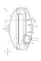
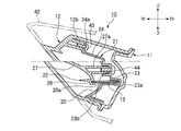
- FIG. 2 is a cross-sectional view taken along line AA in FIG. 1.
- FIG. 3 is a cross-sectional view taken along line BB in FIG. 1. It is CC sectional view taken on the line of FIG.
- FIG. 3 is a cross-sectional view taken along line DD in FIG. 2.
- the front of the vehicle is indicated as Fr, the rear as Rr, the left as L, the right as R, the upper as U, and the lower as D.
- the tail light device 10 of the present embodiment is disposed between a case 11, a lens 12 whose front opening is closed by the case 11, and the case 11 and the lens 12.
- a substrate 13, a first reflector 21 provided at the front end of the substrate 13, a second reflector 22 provided at the rear end of the substrate 13, and a taillight LED 31 and a stoplight LED 32 provided on the substrate 13 are provided.
- the case 11 is formed of a synthetic resin, and as shown in FIGS. 2 and 3, a mounting bracket 11a for mounting the taillight device 10 on the vehicle side is formed at the lower part of the center in the vehicle width direction.
- the case 11 is formed with an air hole 11 b that adjusts the pressure in the taillight device 10 at the lower part on the left side in the vehicle width direction.
- the connector 41 connected to the harness not shown is provided in the lower part of the vehicle width direction right side.
- the lens 12 is formed of a synthetic resin having translucency, and is formed in a substantially triangular shape in a longitudinal sectional view that becomes a tapered shape as it goes rearward. Further, as shown in FIGS. 1 to 3, the lens 12 has an engagement for engaging an engagement portion 42a formed at the rear end portion of the rear cowl 42 at the center in the vehicle width direction on the upper surface of the rear end portion. A concavity 12a is formed.
- the board 13 is disposed horizontally or substantially horizontally along the front-rear direction of the vehicle, and is sandwiched by the first reflector 21 and the second reflector 22 from the front-rear direction.
- a tail light LED 31 is provided on the case 11 side at the front part of the upper surface of the substrate 13, and a stop light LED 32 is provided on the lens 12 side at the rear part of the upper surface.
- the LEDs 32 are spaced apart from each other at the top of the substrate 13.
- the taillight LED 31 and the stoplight LED 32 are configured by arranging a plurality of LEDs (Light Emitting Diode) along the vehicle width direction.
- the stoplight LED 32 is provided in the lower part of the substrate 13 symmetrically with the upper part.
- the first reflector 21 has a substrate holding portion 23 that supports the case 11 side at the front end of the substrate 13, and extends in a curved shape from the upper portion of the substrate holding portion 23 to the rear and upward. And a second reflecting portion 24 that reflects light emitted from the taillight LED 31 and a second reflecting portion that extends backward and downward from the lower portion of the substrate holding portion 23 and reflects light emitted from the stoplight LED 32. And a reflection unit 25.
- a fixing piece 24 a formed at the upper end portion of the first reflecting portion 24 is fastened by a fixing screw 43 to a boss portion 12 b formed at the back surface of the lens 12. .
- the first reflector 21 is supported by the lens 12.
- the second reflector 22 is provided with a substrate holding portion 26 that supports the lens 12 side at the rear end of the substrate 13, and a curved shape extending backward and upward from the substrate holding portion 26. And a third reflector 27 that reflects light emitted from the taillight LED 31 on the back surface and reflects light emitted from the stoplight LED 32 on the front surface.
- the second reflector 22 has a boss portion 27 a formed on the back surface of the third reflecting portion 27 fitted in a recess portion 23 b formed on the rear surface of the substrate holding portion 23 of the first reflector 21. And fastened by a fixing screw 44. Thereby, the 2nd reflector 22 is supported by the 1st reflector 21, and is mutually couple
- the second reflector 22 is formed with a fitting convex portion 27 b from the back surface of the third reflecting portion 27 toward the front, and the fitting convex portion 27 b is fitted.
- a fitting recess 23 c is formed on the rear surface of the substrate holder 23 of the first reflector 21. And the 1st reflector 21 and the 2nd reflector 22 are positioned with high precision by fitting the fitting convex part 27b in the fitting recessed part 23c.
- the taillight LED 31 and the stoplight LED 32 are spaced apart from each other on the front and back of the substrate 13, and as shown in FIG.
- the second reflector 22 is disposed so as to partition the LED 32 for use.
- a groove 23a for inserting the front end of the substrate 13 is formed in the substrate holding portion 23 of the first reflector 21, and the substrate holding portion 26 of the second reflector 22 is formed.
- a groove portion 26a for inserting the rear end of the substrate 13 is formed.
- the board 13 is electrically connected to a lighting device control device (not shown) mounted on the vehicle via a connector 41, and the tail light LED 31 and the stoplight LED are supplied by a signal given from the lighting device control device.
- Each LED 32 is caused to emit light.
- the light emitted from the taillight LED 31 is reflected by the first reflecting portion 24 and the third reflecting portion 27 and then passes through the taillight display portion 14 formed in the upper half of the lens 12.
- the taillight display unit 14 is turned on.
- the light emitted from the stoplight LED 32 is reflected by the second reflecting portion 25 and then passes through the stoplight display portion 15 formed in the lower half of the lens 12 to turn on the stoplight display portion 15.
- the lens cut of the stop light display unit 15 is set at a finer interval than the lens cut of the tail light display unit 14.
- the substrate 13 is arranged along the front-rear direction of the vehicle, the first reflector 21 is provided on the case 11 side at the front end of the substrate 13, and Since the second reflector 22 is provided on the lens 12 side at the rear end and the substrate 13 is sandwiched between the first reflector 21 and the second reflector 22, the support strength of the substrate 13 can be improved. Moreover, since the board
- the second reflector 22 is connected to the first reflector 21, so that the support strength of the substrate 13 can be improved. Further, the positioning of the second reflector 22 with respect to the first reflector 21 can be facilitated.
- the tail light device 10 of the present embodiment since the first reflector 21 is supported by the lens 12, the positioning of the first reflector 21 and the second reflector 22 with respect to the lens 12 can be facilitated.
- the taillight LED 31 and the stoplight LED 32 are provided, and the taillight LED 31 and the stoplight LED 32 are arranged on the upper side of the substrate 13 so as to be separated from each other in the front-rear direction. Since the second reflector 22 is disposed between the taillight LED 31 and the stoplight LED 32, the height of the taillight device 10 can be reduced, and the taillight device 10 can be downsized. .
- the support strength of the substrate 13 is further improved. Can do.
Landscapes
- Engineering & Computer Science (AREA)
- General Engineering & Computer Science (AREA)
- Mechanical Engineering (AREA)
- Physics & Mathematics (AREA)
- Microelectronics & Electronic Packaging (AREA)
- Optics & Photonics (AREA)
- Non-Portable Lighting Devices Or Systems Thereof (AREA)
Abstract
Priority Applications (4)
| Application Number | Priority Date | Filing Date | Title |
|---|---|---|---|
| PCT/JP2008/054024 WO2009110080A1 (fr) | 2008-03-06 | 2008-03-06 | Unité de feu arrière |
| JP2009531652A JP5266233B2 (ja) | 2008-03-06 | 2008-03-06 | テールライト装置 |
| US12/920,846 US8313223B2 (en) | 2008-03-06 | 2008-03-06 | Taillight apparatus |
| EP08721444.1A EP2261555B1 (fr) | 2008-03-06 | 2008-03-06 | Unité de feu arrière |
Applications Claiming Priority (1)
| Application Number | Priority Date | Filing Date | Title |
|---|---|---|---|
| PCT/JP2008/054024 WO2009110080A1 (fr) | 2008-03-06 | 2008-03-06 | Unité de feu arrière |
Publications (1)
| Publication Number | Publication Date |
|---|---|
| WO2009110080A1 true WO2009110080A1 (fr) | 2009-09-11 |
Family
ID=41055659
Family Applications (1)
| Application Number | Title | Priority Date | Filing Date |
|---|---|---|---|
| PCT/JP2008/054024 Ceased WO2009110080A1 (fr) | 2008-03-06 | 2008-03-06 | Unité de feu arrière |
Country Status (4)
| Country | Link |
|---|---|
| US (1) | US8313223B2 (fr) |
| EP (1) | EP2261555B1 (fr) |
| JP (1) | JP5266233B2 (fr) |
| WO (1) | WO2009110080A1 (fr) |
Cited By (9)
| Publication number | Priority date | Publication date | Assignee | Title |
|---|---|---|---|---|
| KR100972840B1 (ko) * | 2009-11-13 | 2010-07-28 | 백순현 | 가로등용 엘이디램프 |
| KR101016923B1 (ko) | 2010-07-23 | 2011-02-25 | 주식회사 티솔루션 | 가로등 및 보안등용 led 등기구 |
| JP2011063109A (ja) * | 2009-09-16 | 2011-03-31 | Honda Motor Co Ltd | 自動二輪車用後部灯火器構造 |
| WO2013149714A1 (fr) | 2012-04-04 | 2013-10-10 | Merck Patent Gmbh | Particules pour dispositifs d'affichage électrophorétiques comprenant un cœur et un revêtement de copolymère aléatoire |
| WO2013170936A1 (fr) | 2012-05-14 | 2013-11-21 | Merck Patent Gmbh | Particules pour écrans électrophorétiques |
| WO2013170932A1 (fr) | 2012-05-14 | 2013-11-21 | Merck Patent Gmbh | Particules pour afficheurs électrophorétiques |
| DE102014205621A1 (de) | 2013-03-29 | 2014-10-02 | Honda Motor Co., Ltd. | Scheinwerfereinrichtung für ein Kraftrad |
| US20150197299A1 (en) * | 2014-01-13 | 2015-07-16 | Specialized Bicycle Components, Inc. | Bicycle taillight with parallel lighting element |
| US9371104B2 (en) | 2013-03-29 | 2016-06-21 | Honda Motor Co., Ltd. | Headlight device for motorcycle |
Families Citing this family (11)
| Publication number | Priority date | Publication date | Assignee | Title |
|---|---|---|---|---|
| WO2011026088A2 (fr) * | 2009-08-31 | 2011-03-03 | Federal-Mogul Corporation | Ensemble d'éclairage pour véhicule |
| DE102012220455A1 (de) * | 2012-11-09 | 2014-05-15 | Osram Gmbh | Leuchtvorrichtung mit halbleiterlichtquelle |
| DE102012112145A1 (de) * | 2012-12-12 | 2014-06-26 | Dr. Ing. H.C. F. Porsche Aktiengesellschaft | Beleuchtungsvorrichtung |
| US9010975B2 (en) | 2013-03-12 | 2015-04-21 | Grote Industries, Inc. | Multi-colored vehicle rear lamp |
| FR3036773B1 (fr) * | 2015-05-27 | 2019-09-13 | Psa Automobiles Sa. | Bloc optique de vehicule a plaque de support de sources de lumiere partagee pour le placement d’une fonction photometrique dans une autre fonction photometrique |
| DE102016205644B4 (de) * | 2016-04-06 | 2024-10-17 | Volkswagen Aktiengesellschaft | Beleuchtungsvorrichtung für ein Kraftfahrzeug |
| DE102017104841A1 (de) * | 2017-03-08 | 2018-09-13 | HELLA GmbH & Co. KGaA | Beleuchtungsvorrichtung für Fahrzeuge sowie Montageverfahren |
| FR3077868B1 (fr) * | 2018-02-09 | 2020-08-14 | Psa Automobiles Sa | Dispositif d’eclairage a face de carte a circuits imprimes associee a deux fonctions photometriques voisines |
| FR3087520B1 (fr) * | 2018-10-19 | 2021-04-09 | Psa Automobiles Sa | Module lumineux assurant deux fonctions photometriques presentant des signatures lumineuses distinctes |
| FR3138498B1 (fr) * | 2022-07-28 | 2024-10-18 | Valeo Vision | Module d’éclairage et de signalisation lumineux |
| FR3146337A1 (fr) * | 2023-03-01 | 2024-09-06 | Psa Automobiles Sa | Bloc optique à carte électronique participant à la séparation entre deux fonctions photométriques |
Citations (6)
| Publication number | Priority date | Publication date | Assignee | Title |
|---|---|---|---|---|
| JPH0545811U (ja) * | 1991-11-15 | 1993-06-18 | 株式会社小糸製作所 | 車輌用標識灯 |
| JP2003054460A (ja) | 2001-08-21 | 2003-02-26 | Honda Motor Co Ltd | 自動二輪車の尾灯構造 |
| JP2003100114A (ja) * | 2001-09-19 | 2003-04-04 | Koito Mfg Co Ltd | 車両用灯具 |
| JP2004247069A (ja) * | 2003-02-10 | 2004-09-02 | Stanley Electric Co Ltd | 車両用灯具 |
| JP2004265697A (ja) * | 2003-02-28 | 2004-09-24 | Toyota Industries Corp | 信号灯具及び信号灯具の反射構造 |
| JP2007059075A (ja) * | 2005-08-22 | 2007-03-08 | Stanley Electric Co Ltd | 車両用灯具 |
Family Cites Families (9)
| Publication number | Priority date | Publication date | Assignee | Title |
|---|---|---|---|---|
| US2717955A (en) * | 1953-06-18 | 1955-09-13 | Thomas Industries Inc | Recessed lighting fixture |
| US2997575A (en) * | 1954-07-23 | 1961-08-22 | Markstone Mfg Company | Recessed lighting fixture |
| US4862334A (en) * | 1989-02-09 | 1989-08-29 | Fasco Industries, Inc. | Lamp, reflector and grille interlock assembly |
| JPH06273765A (ja) * | 1993-01-19 | 1994-09-30 | Canon Inc | バックライト装置及びそれを用いた液晶ディスプレイ装置 |
| US5803579A (en) * | 1996-06-13 | 1998-09-08 | Gentex Corporation | Illuminator assembly incorporating light emitting diodes |
| JP4094366B2 (ja) * | 2002-07-24 | 2008-06-04 | 株式会社小糸製作所 | 車両用灯具 |
| JP4206943B2 (ja) | 2004-03-19 | 2009-01-14 | 豊田合成株式会社 | 車両用照明装置 |
| WO2005028250A1 (fr) | 2003-09-22 | 2005-03-31 | Decoma International Inc. | Ensemble de feux de vehicule |
| FR2907880B1 (fr) * | 2006-10-27 | 2015-07-10 | Valeo Vision | Dispositif d'eclairage ou de signalisation comportant deux sources lumineuses agencees sur les deux faces d'un support commun. |
-
2008
- 2008-03-06 WO PCT/JP2008/054024 patent/WO2009110080A1/fr not_active Ceased
- 2008-03-06 EP EP08721444.1A patent/EP2261555B1/fr not_active Not-in-force
- 2008-03-06 JP JP2009531652A patent/JP5266233B2/ja not_active Expired - Fee Related
- 2008-03-06 US US12/920,846 patent/US8313223B2/en not_active Expired - Fee Related
Patent Citations (6)
| Publication number | Priority date | Publication date | Assignee | Title |
|---|---|---|---|---|
| JPH0545811U (ja) * | 1991-11-15 | 1993-06-18 | 株式会社小糸製作所 | 車輌用標識灯 |
| JP2003054460A (ja) | 2001-08-21 | 2003-02-26 | Honda Motor Co Ltd | 自動二輪車の尾灯構造 |
| JP2003100114A (ja) * | 2001-09-19 | 2003-04-04 | Koito Mfg Co Ltd | 車両用灯具 |
| JP2004247069A (ja) * | 2003-02-10 | 2004-09-02 | Stanley Electric Co Ltd | 車両用灯具 |
| JP2004265697A (ja) * | 2003-02-28 | 2004-09-24 | Toyota Industries Corp | 信号灯具及び信号灯具の反射構造 |
| JP2007059075A (ja) * | 2005-08-22 | 2007-03-08 | Stanley Electric Co Ltd | 車両用灯具 |
Non-Patent Citations (1)
| Title |
|---|
| See also references of EP2261555A4 * |
Cited By (11)
| Publication number | Priority date | Publication date | Assignee | Title |
|---|---|---|---|---|
| JP2011063109A (ja) * | 2009-09-16 | 2011-03-31 | Honda Motor Co Ltd | 自動二輪車用後部灯火器構造 |
| KR100972840B1 (ko) * | 2009-11-13 | 2010-07-28 | 백순현 | 가로등용 엘이디램프 |
| KR101016923B1 (ko) | 2010-07-23 | 2011-02-25 | 주식회사 티솔루션 | 가로등 및 보안등용 led 등기구 |
| WO2013149714A1 (fr) | 2012-04-04 | 2013-10-10 | Merck Patent Gmbh | Particules pour dispositifs d'affichage électrophorétiques comprenant un cœur et un revêtement de copolymère aléatoire |
| WO2013170936A1 (fr) | 2012-05-14 | 2013-11-21 | Merck Patent Gmbh | Particules pour écrans électrophorétiques |
| WO2013170932A1 (fr) | 2012-05-14 | 2013-11-21 | Merck Patent Gmbh | Particules pour afficheurs électrophorétiques |
| DE102014205621A1 (de) | 2013-03-29 | 2014-10-02 | Honda Motor Co., Ltd. | Scheinwerfereinrichtung für ein Kraftrad |
| US9371104B2 (en) | 2013-03-29 | 2016-06-21 | Honda Motor Co., Ltd. | Headlight device for motorcycle |
| US9676436B2 (en) | 2013-03-29 | 2017-06-13 | Honda Motor Co., Ltd. | Headlight device for motorcycle |
| DE102014205621B4 (de) | 2013-03-29 | 2020-08-06 | Honda Motor Co., Ltd. | Scheinwerfereinrichtung für ein Kraftrad |
| US20150197299A1 (en) * | 2014-01-13 | 2015-07-16 | Specialized Bicycle Components, Inc. | Bicycle taillight with parallel lighting element |
Also Published As
| Publication number | Publication date |
|---|---|
| EP2261555A1 (fr) | 2010-12-15 |
| US20110273899A1 (en) | 2011-11-10 |
| US8313223B2 (en) | 2012-11-20 |
| JP5266233B2 (ja) | 2013-08-21 |
| JPWO2009110080A1 (ja) | 2011-07-14 |
| EP2261555B1 (fr) | 2014-10-15 |
| EP2261555A4 (fr) | 2011-03-02 |
Similar Documents
| Publication | Publication Date | Title |
|---|---|---|
| JP5266233B2 (ja) | テールライト装置 | |
| JP4996951B2 (ja) | テールランプ構造 | |
| CN1862085B (zh) | 三色发光二极管泡体 | |
| JP5543228B2 (ja) | 面発光体を備えた車両用灯具 | |
| US20140140081A1 (en) | Vehicular lamp | |
| US9452707B1 (en) | Vehicle light apparatus | |
| CN103402861A (zh) | 用于车辆的照明装置以及用于该装置的安装结构 | |
| US9688332B2 (en) | Headlamp assembly for a saddle-type vehicle | |
| CN108779903A (zh) | 照明装置 | |
| JP5486175B2 (ja) | 尾灯装置 | |
| JP2018037274A (ja) | 車輌用灯具 | |
| CN111174170B (zh) | 车辆用灯具 | |
| JP6426577B2 (ja) | 車両用リアコンビネーションランプ及び車両 | |
| CN110462284B (zh) | 鞍乘式车辆的照明装置 | |
| US8845153B2 (en) | High beam and low beam combination lamp for a bicycle | |
| JP6054093B2 (ja) | 車両用灯具 | |
| EP3150430B1 (fr) | Feu arrière combiné pour véhicule et véhicule | |
| JP3176119U (ja) | 自転車用テールランプ | |
| CN111038627B (zh) | 跨坐型车辆 | |
| KR101865943B1 (ko) | 차량용 등화장치 | |
| TWM495973U (zh) | 複合燈 | |
| TWI642876B (zh) | Car headlight | |
| JP6324017B2 (ja) | 車輌用灯具 | |
| JP2014103061A (ja) | ライセンスランプ一体型テールランプ | |
| JP7299096B2 (ja) | 二輪車用灯具 |
Legal Events
| Date | Code | Title | Description |
|---|---|---|---|
| ENP | Entry into the national phase |
Ref document number: 2009531652 Country of ref document: JP Kind code of ref document: A |
|
| 121 | Ep: the epo has been informed by wipo that ep was designated in this application |
Ref document number: 08721444 Country of ref document: EP Kind code of ref document: A1 |
|
| NENP | Non-entry into the national phase |
Ref country code: DE |
|
| WWE | Wipo information: entry into national phase |
Ref document number: 2008721444 Country of ref document: EP |
|
| WWE | Wipo information: entry into national phase |
Ref document number: 12920846 Country of ref document: US |