WO2009110180A1 - Procédé de fabrication d'un gabarit et procédé de polissage dans lequel le gabarit est utilisé - Google Patents
Procédé de fabrication d'un gabarit et procédé de polissage dans lequel le gabarit est utilisé Download PDFInfo
- Publication number
- WO2009110180A1 WO2009110180A1 PCT/JP2009/000699 JP2009000699W WO2009110180A1 WO 2009110180 A1 WO2009110180 A1 WO 2009110180A1 JP 2009000699 W JP2009000699 W JP 2009000699W WO 2009110180 A1 WO2009110180 A1 WO 2009110180A1
- Authority
- WO
- WIPO (PCT)
- Prior art keywords
- template
- polishing
- workpiece
- glass epoxy
- thickness
- Prior art date
- Legal status (The legal status is an assumption and is not a legal conclusion. Google has not performed a legal analysis and makes no representation as to the accuracy of the status listed.)
- Ceased
Links
Images


Classifications
-
- B—PERFORMING OPERATIONS; TRANSPORTING
- B24—GRINDING; POLISHING
- B24B—MACHINES, DEVICES, OR PROCESSES FOR GRINDING OR POLISHING; DRESSING OR CONDITIONING OF ABRADING SURFACES; FEEDING OF GRINDING, POLISHING, OR LAPPING AGENTS
- B24B37/00—Lapping machines or devices; Accessories
- B24B37/27—Work carriers
- B24B37/30—Work carriers for single side lapping of plane surfaces
- B24B37/32—Retaining rings
Definitions
- the present invention relates to a method for manufacturing a template (TP) for holding a workpiece when polishing the surface of the workpiece, such as a semiconductor wafer including a silicon wafer, and a polishing method using the same.
- TP template
- the present invention relates to a method for manufacturing a template (TP) for holding a workpiece when polishing the surface of the workpiece, such as a semiconductor wafer including a silicon wafer, and a polishing method using the same.
- High precision flatness is required for semiconductor manufacturing wafers and the like.
- a polishing process is indispensable for the manufacture of those which require high precision flatness.
- an electronic device member typified by a semiconductor manufacturing wafer is required to have nano-order processing accuracy.
- the constant pressure sliding mechanical chemical polishing method is most frequently used practically in the production process of silicon wafers for semiconductor manufacturing. This method is a method in which a silicon wafer is pressed against a rotating table with a polishing cloth and a polishing agent mixed with fine abrasive grains that perform a mechanical removal action and a chemical solution that performs an etching action is supplied for polishing. is there.
- fine abrasive grains SiO 2 particles are used.
- an aqueous alkali hydroxide solution is used as the chemical solution.
- mechanochemical polishing methods that use particles that are softer than the workpiece and capable of causing a chemical reaction with the workpiece have also been used.
- an elastic pad such as polyurethane is attached to the lower surface of a disk-shaped carrier made of a flexible film or ceramic, and this pad is attached to the pad. Moisture is absorbed and the work is held by surface tension. Further, in order to prevent the carrier from coming off from the workpiece during polishing, a template made of glass epoxy (EG) attached to the outer periphery of the elastic pad is used as a template (for example, Japanese Patent Laid-Open No. 10-146754). See the official gazette).
- EG glass epoxy
- the present invention is a template that can keep the in-plane flatness high when a workpiece is polished, and in particular, can suppress the deterioration of the surface shape of the outer periphery of the workpiece. It is an object of the present invention to provide a manufacturing method and a workpiece polishing method using such a template.
- the present invention provides a template manufacturing method for holding the workpiece when polishing the workpiece, comprising at least a step of preparing a glass epoxy substrate, wrapping the glass epoxy substrate, and There is provided a method for producing a template, comprising: a step of polishing, a step of opening a hole for holding a workpiece in the glass epoxy substrate, and a step of attaching the glass epoxy substrate and an elastic pad.
- the glass epoxy substrate has a thickness of 50 ⁇ m, it is difficult to bring the thickness of the workpiece to be polished close to the thickness of the template, and it is difficult to improve the flatness of the outer periphery of the workpiece. It was.
- the glass epoxy substrate has a thickness variation of 50 ⁇ m or more in the plane, there is a partial difference between the thickness of the template made using such a glass epoxy substrate and the thickness of the workpiece. Therefore, it was found that the surface shape of the outer periphery of the work partly deteriorated due to the difference in thickness.
- the thickness of the workpiece to be polished and the thickness of the template can be freely set.
- the thickness of the workpiece and the thickness of the template can be easily brought close to each other, and the flatness of the outer peripheral portion of the workpiece can be improved.
- the in-plane thickness variation of the glass epoxy substrate can be suppressed lower than conventional, and the in-plane thickness variation when used as a template can be suppressed. . Therefore, the template which can suppress that the surface shape of a workpiece
- the step of lapping and / or polishing the glass epoxy substrate can make the thickness variation in the surface of the glass epoxy substrate 10 ⁇ m or less.
- the difference between the partial template thickness and the workpiece thickness can be made sufficiently small. It is possible to further suppress the partial deterioration of the surface shape and obtain a uniform workpiece in the surface.
- polishing process shall perform double-sided grinding
- polishing when the glass epoxy substrate is polished, by performing double-side polishing, when the manufactured glass epoxy substrate and the elastic pad are bonded, the bonding surface with the elastic pad can be flattened, and Since the variation in the thickness of the glass epoxy substrate can be reduced, the template can be made flatter, and therefore, it is further suppressed that the difference between the thickness of the template and the thickness of the workpiece is partially increased. Therefore, it is possible to suppress the surface shape of the outer peripheral portion of the workpiece from partially deteriorating in the plane.
- a method for polishing the surface of a workpiece the template manufactured by the template manufacturing method described in the present invention is attached to the lower surface of the carrier, and then the workpiece is held in the hole for holding the workpiece.
- a method for polishing a workpiece wherein the workpiece is held by the carrier, and the workpiece is polished by being brought into sliding contact with a predetermined pressing force while rotating the workpiece against a polishing cloth on a surface plate. I will provide a.
- the template manufactured by the template manufacturing method according to the present invention can set the difference between the workpiece thickness and the template thickness to a desired value, and the thickness variation in the template surface is larger than the conventional one. Since it can be kept low, by polishing the workpiece using such a template, the surface shape of the outer peripheral portion of the workpiece can be prevented from partially deteriorating, and the workpiece can be uniformly polished in the plane. .
- the template manufacturing method of the present invention is capable of freely controlling the difference in thickness between the workpiece and the template, and manufacturing a template that can improve the flatness (particularly the outer peripheral portion) of the workpiece. Can do.
- variations in the thickness of the template itself can be suppressed, whereby a template capable of making the surface shape of the outer periphery of the workpiece uniform in the surface can be manufactured.
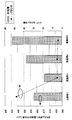
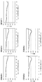
- FIG. 6 is a graph showing evaluation results of thickness and thickness variation of glass epoxy substrates in templates in Examples 1 to 3 and Comparative Example 1 of the present invention. 6 is a graph showing how much the in-plane shape of a silicon wafer polished using the templates of Examples 5 to 9 of the present invention changes before and after polishing.
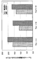
- FIG. 6 is a diagram comparing surface shapes after polishing of silicon wafers polished using the templates of Examples 1 to 4 of the present invention. It is the graph which compared the variation of ZDD of the silicon wafer ground using the template of Example 4 and comparative example 1 of the present invention.
- the present inventors first investigated the cause of the deterioration of the surface shape of the outer periphery of the workpiece.
- the glass epoxy substrate of the template as purchased has a thickness usually in increments of 50 ⁇ m and an in-plane thickness variation of about 50 ⁇ m exists on average.
- it since it has such thickness and thickness variation, it is difficult to make the thickness of the workpiece and the thickness of the template close to each other, so it is difficult to improve the flatness of the outer periphery, and in the plane
- the surface shape in the vicinity of the outer peripheral portion was partially deteriorated due to the difference between the thickness of the template and the thickness of the workpiece.
- the inventors of the present invention made extensive studies and prepared a glass epoxy substrate as a base material for the template instead of using the template purchased from the manufacturer as it is for polishing. It was discovered that by polishing and / or polishing, the difference between the thickness of the workpiece and the thickness of the template can be controlled, and the variation in the in-plane thickness can be suppressed to prevent the surface shape of the workpiece from deteriorating.
- the present invention has been completed.
- FIG. 1 is a schematic diagram showing the relationship between a template and a carrier in the present invention.
- a work W includes a carrier 11 and a glass epoxy substrate (also referred to as a glass epoxy ring) 13 that is attached to the carrier 11 via a backing pad 12 and has a hole for holding the work W.
- the shape is held by the template 10.
- the glass epoxy ring 13 is comprised with the glass epoxy, and this glass epoxy is what lapped and / or polished.
- the template as described above can be manufactured by a template manufacturing method as exemplified below, but is not limited to this.
- the glass epoxy substrate prepared here is not particularly limited, and the shape such as thickness and size can be arbitrary, but the shape is preferably a disc shape.
- lapping and / or polishing is performed on the prepared glass epoxy substrate.
- This lapping and polishing can be performed only on one side or of course both. If lapping is performed, the machining allowance is large, so that the thickness can be easily adjusted. If polishing is performed, the surface can be made flatter.
- alumina-based or SiC-based abrasive particles can be used as the abrasive particles.
- the alkaline solution containing colloidal silica can be used, for example.
- the thickness of the glass epoxy substrate after polishing is preferably such that the difference from the workpiece to be polished is, for example, 100 ⁇ m or less.
- the flatness of the outer periphery of the workpiece can be further improved by setting the difference in thickness between the glass epoxy substrate and the workpiece to 100 ⁇ m or less.
- the abrasive grains and alkali solution adhering by lapping and / or polishing can be removed by pure water + ultrasonic waves or alkali cleaning.
- the in-plane thickness variation of the glass epoxy substrate can be 10 ⁇ m or less.
- the in-plane thickness variation of the glass epoxy substrate can be 10 ⁇ m or less.
- double-side polishing can be performed.
- the double-side polishing is performed so that the attachment surface of the carrier and the glass epoxy substrate attached via the elastic pad is flat and has a small thickness variation. Can do. Therefore, the difference between the thickness of the template and the thickness of the workpiece can be further reduced, and therefore the surface shape of the outer peripheral portion of the workpiece can be prevented from being partially deteriorated.
- NC processing is suitable for the process of making this hole, but it is not limited to this. Here, it is desirable to perform the above-described cleaning process even after the processing.
- a template can be obtained by attaching an elastic pad to a glass epoxy substrate with a hole.
- the glass epoxy substrate can be lapped and / or polished, and then processed into a template. For this reason, the difference in thickness between the workpiece and the template can be freely controlled, and variation in thickness within the surface of the template itself can be suppressed. Therefore, the template which can improve the flatness of a workpiece
- the step of lapping and / or polishing is performed first, and the step of opening the hole for holding the workpiece is performed later, but this order can be reversed. It can also be set as the process of lapping and / or grinding
- the template manufactured by the manufacturing method of the present invention can freely control the difference in thickness between the workpiece and the template, and can suppress variations in the thickness of the template itself. Therefore, by polishing the workpiece using such a template, the flatness of the outer periphery of the workpiece is good, and the surface shape of the outer periphery of the workpiece is prevented from being partially deteriorated. It can be set as the grinding
- Example 1 to 9 and Comparative Example 1 First, a glass epoxy substrate having a diameter of 365 mm and a thickness of 850 ⁇ m was prepared, and lapping or polishing was performed until a predetermined thickness was obtained. In this lapping, FO (alumina-based lapping agent) manufactured by Fujimi Incorporated was used for the abrasive grains. In polishing, an alkaline solution containing colloidal silica was used as an abrasive. Thereafter, the glass epoxy substrate was cleaned by immersing the glass epoxy substrate in pure water and then performing ultrasonic waves.
- FO alumina-based lapping agent manufactured by Fujimi Incorporated
- a hole for holding a silicon wafer having a diameter of 300 mm was formed in the glass epoxy substrate by NC processing, and the glass epoxy substrate in which the hole was formed by ultrasonic cleaning was again washed after being immersed in pure water. Then, a foamed urethane backing pad was attached to complete the template.
- the predetermined thickness of the glass epoxy substrate after lapping or polishing and the processing method are as shown in Table 1 described later.
- the prepared template was mounted on a polishing head, and a silicon wafer having a diameter of 300 mm was polished.
- a non-woven fabric type was used as the polishing cloth, and an alkaline solution containing colloidal silica was used as the polishing agent.
- the polishing head and the polishing surface plate were each rotated at 30 rpm.
- the polishing pressure of the wafer was 100 to 130 g / cm 2 .
- the silicon wafer was polished using the template of Examples 5 to 9, and the surface of the silicon wafer before and after polishing It was evaluated how the shape was changed by polishing. The result is shown in FIG. Regarding how much the surface shape of the wafer differs depending on the thickness of the glass epoxy substrate in the template, the silicon wafer was polished using the templates of Examples 1 to 4, and the surface shapes were compared thereafter. The result is shown in FIG. Using the templates of Example 4 and Comparative Example 1, three silicon wafers were polished, and the ZDD variation on the polished wafer surface was compared. The result is shown in FIG.
- the thickness of the glass epoxy substrate in the template becomes thinner, the allowance at the outer peripheral portion of the wafer becomes larger.
- the shape of the polishing allowance of the wafer in polishing can be changed. That is, it was found that the shape of the outer peripheral portion of the wafer after polishing can be controlled by setting the thickness of the template to a desired thickness.
- the surface shape of the wafer changes by changing the thickness of the glass epoxy substrate in the template.
- a wafer polished using the template of Example 3 with a glass epoxy substrate thickness of 840 ⁇ m is compared to a wafer polished with the template of Example 4 with a glass epoxy substrate thickness of 810 ⁇ m.
- the shape of the outer peripheral portion was changed, and that the difference in thickness between the outer peripheral portion and the central portion of the wafer became smaller as the thickness of the glass epoxy substrate in the template became thinner.
- the wafer polished using the template of Example 4 has a more stable ZDD value at the outer periphery of the wafer than the wafer polished using the template of Comparative Example 1, and It was found that the surface shape was not partially deteriorated and could be polished uniformly.
- ZDD refers to a method in which the height of the wafer is differentiated twice by the length in the radial direction of the wafer in a method of measuring and evaluating the curvature shape near the edge of the wafer.
- the present invention is not limited to the above embodiment.
- the above-described embodiment is an exemplification, and the present invention has any configuration that has substantially the same configuration as the technical idea described in the claims of the present invention and that exhibits the same effects. Are included in the technical scope.
Landscapes
- Engineering & Computer Science (AREA)
- Mechanical Engineering (AREA)
- Finish Polishing, Edge Sharpening, And Grinding By Specific Grinding Devices (AREA)
Abstract
L'invention porte sur un procédé de fabrication d'un gabarit qui maintient une pièce à travailler lors du polissage de la pièce à travailler. Le procédé comporte au moins une étape de préparation d'un substrat en verre-époxy ; une étape de rodage et/ou polissage du substrat en verre-époxy ; et une étape de réalisation d'un trou sur le substrat en verre-époxy pour maintenir la pièce à travailler. Ainsi, le procédé permet de fabriquer le gabarit qui peut conserver une planéité dans le plan, en particulier supprimer une détérioration de la forme de surface de la section périphérique externe de la pièce à travailler lorsque la pièce à travailler est polie.
Applications Claiming Priority (2)
| Application Number | Priority Date | Filing Date | Title |
|---|---|---|---|
| JP2008054003A JP5169321B2 (ja) | 2008-03-04 | 2008-03-04 | ワークの研磨方法 |
| JP2008-054003 | 2008-03-04 |
Publications (1)
| Publication Number | Publication Date |
|---|---|
| WO2009110180A1 true WO2009110180A1 (fr) | 2009-09-11 |
Family
ID=41055745
Family Applications (1)
| Application Number | Title | Priority Date | Filing Date |
|---|---|---|---|
| PCT/JP2009/000699 Ceased WO2009110180A1 (fr) | 2008-03-04 | 2009-02-19 | Procédé de fabrication d'un gabarit et procédé de polissage dans lequel le gabarit est utilisé |
Country Status (2)
| Country | Link |
|---|---|
| JP (1) | JP5169321B2 (fr) |
| WO (1) | WO2009110180A1 (fr) |
Cited By (2)
| Publication number | Priority date | Publication date | Assignee | Title |
|---|---|---|---|---|
| US8926400B2 (en) | 2012-03-07 | 2015-01-06 | HGST Netherlands B.V. | Uniformity during planarization of a disk |
| WO2017061077A1 (fr) * | 2015-10-07 | 2017-04-13 | 信越半導体株式会社 | Procédé de mesure et procédé d'évaluation de modèle |
Families Citing this family (1)
| Publication number | Priority date | Publication date | Assignee | Title |
|---|---|---|---|---|
| JP5821883B2 (ja) | 2013-03-22 | 2015-11-24 | 信越半導体株式会社 | テンプレートアセンブリ及びテンプレートアセンブリの製造方法 |
Citations (5)
| Publication number | Priority date | Publication date | Assignee | Title |
|---|---|---|---|---|
| JPS62236671A (ja) * | 1986-04-08 | 1987-10-16 | Mitsubishi Metal Corp | 被研磨材の保持装置 |
| JPH10146754A (ja) * | 1996-11-14 | 1998-06-02 | Hitachi Chem Co Ltd | 研磨用テンプレート材料 |
| JPH11277419A (ja) * | 1998-03-31 | 1999-10-12 | Shin Etsu Handotai Co Ltd | バッキングパッドの平坦度矯正方法 |
| JP2000042910A (ja) * | 1998-07-28 | 2000-02-15 | Rooder Nitta Kk | 研磨用被加工物保持具 |
| JP2004200438A (ja) * | 2002-12-19 | 2004-07-15 | Sumitomo Electric Ind Ltd | ワックスレス研磨方法とワックスレス研磨のための吸着パッド |
Family Cites Families (5)
| Publication number | Priority date | Publication date | Assignee | Title |
|---|---|---|---|---|
| JP4019349B2 (ja) * | 2001-12-20 | 2007-12-12 | 株式会社Sumco | ワックスレスマウント式研磨装置 |
| JP2003197580A (ja) * | 2001-12-21 | 2003-07-11 | Fujikoshi Mach Corp | ウェーハ研磨装置 |
| JP2003236743A (ja) * | 2002-02-15 | 2003-08-26 | Rodel Nitta Co | 研磨用テンプレート |
| JP4154526B2 (ja) * | 2003-08-26 | 2008-09-24 | 株式会社村田製作所 | ラップ加工用キャリアの厚み加工方法 |
| JP2006205265A (ja) * | 2005-01-25 | 2006-08-10 | Speedfam Co Ltd | 研磨方法および研磨用組成物 |
-
2008
- 2008-03-04 JP JP2008054003A patent/JP5169321B2/ja active Active
-
2009
- 2009-02-19 WO PCT/JP2009/000699 patent/WO2009110180A1/fr not_active Ceased
Patent Citations (5)
| Publication number | Priority date | Publication date | Assignee | Title |
|---|---|---|---|---|
| JPS62236671A (ja) * | 1986-04-08 | 1987-10-16 | Mitsubishi Metal Corp | 被研磨材の保持装置 |
| JPH10146754A (ja) * | 1996-11-14 | 1998-06-02 | Hitachi Chem Co Ltd | 研磨用テンプレート材料 |
| JPH11277419A (ja) * | 1998-03-31 | 1999-10-12 | Shin Etsu Handotai Co Ltd | バッキングパッドの平坦度矯正方法 |
| JP2000042910A (ja) * | 1998-07-28 | 2000-02-15 | Rooder Nitta Kk | 研磨用被加工物保持具 |
| JP2004200438A (ja) * | 2002-12-19 | 2004-07-15 | Sumitomo Electric Ind Ltd | ワックスレス研磨方法とワックスレス研磨のための吸着パッド |
Cited By (3)
| Publication number | Priority date | Publication date | Assignee | Title |
|---|---|---|---|---|
| US8926400B2 (en) | 2012-03-07 | 2015-01-06 | HGST Netherlands B.V. | Uniformity during planarization of a disk |
| WO2017061077A1 (fr) * | 2015-10-07 | 2017-04-13 | 信越半導体株式会社 | Procédé de mesure et procédé d'évaluation de modèle |
| US10661410B2 (en) | 2015-10-07 | 2020-05-26 | Shin-Etsu Handotai Co., Ltd. | Method for measuring template and method for evaluating same |
Also Published As
| Publication number | Publication date |
|---|---|
| JP2009208199A (ja) | 2009-09-17 |
| JP5169321B2 (ja) | 2013-03-27 |
Similar Documents
| Publication | Publication Date | Title |
|---|---|---|
| JP4093793B2 (ja) | 半導体ウエーハの製造方法及びウエーハ | |
| JP4038429B2 (ja) | ウェーハの製造方法及び研磨装置並びにウェーハ | |
| JP5995825B2 (ja) | 少なくとも1つのウエハを研磨する方法 | |
| KR100818683B1 (ko) | 경면 면취 웨이퍼, 경면 면취용 연마 클로스 및 경면 면취연마장치 및 방법 | |
| US9293318B2 (en) | Semiconductor wafer manufacturing method | |
| JP3664676B2 (ja) | ウェーハの研磨方法及びウェーハ研磨用研磨パッド | |
| WO2006046403A1 (fr) | Procede de production de tranche a semi-conducteurs et tranche a semi-conducteurs | |
| JP6027346B2 (ja) | 半導体ウェーハの製造方法 | |
| JP5169321B2 (ja) | ワークの研磨方法 | |
| JP2005205543A (ja) | ウエーハの研削方法及びウエーハ | |
| WO2004109787A1 (fr) | Procede pour polir une tranche | |
| JP6796978B2 (ja) | 半導体装置の製造方法 | |
| JP6717706B2 (ja) | ウェハの表面処理装置 | |
| JP6406048B2 (ja) | ウェハの加工方法 | |
| JP2018032735A (ja) | ウェハの表面処理方法 | |
| KR101581469B1 (ko) | 웨이퍼 연마방법 | |
| JPH09272053A (ja) | 半導体ウェーハの鏡面研磨方法とドレッシング材 | |
| JP2003039310A (ja) | ウェーハの研磨方法及びウェーハ | |
| JP2007035917A (ja) | 研磨パッド、シリコンウエハおよび研磨機 |
Legal Events
| Date | Code | Title | Description |
|---|---|---|---|
| 121 | Ep: the epo has been informed by wipo that ep was designated in this application |
Ref document number: 09717490 Country of ref document: EP Kind code of ref document: A1 |
|
| NENP | Non-entry into the national phase |
Ref country code: DE |
|
| 122 | Ep: pct application non-entry in european phase |
Ref document number: 09717490 Country of ref document: EP Kind code of ref document: A1 |