WO2009113567A1 - マイクロ流体デバイス - Google Patents
マイクロ流体デバイス Download PDFInfo
- Publication number
- WO2009113567A1 WO2009113567A1 PCT/JP2009/054623 JP2009054623W WO2009113567A1 WO 2009113567 A1 WO2009113567 A1 WO 2009113567A1 JP 2009054623 W JP2009054623 W JP 2009054623W WO 2009113567 A1 WO2009113567 A1 WO 2009113567A1
- Authority
- WO
- WIPO (PCT)
- Prior art keywords
- gas
- substrate
- microfluidic device
- gas generation
- layer
- Prior art date
- Legal status (The legal status is an assumption and is not a legal conclusion. Google has not performed a legal analysis and makes no representation as to the accuracy of the status listed.)
- Ceased
Links
Images






Classifications
-
- F—MECHANICAL ENGINEERING; LIGHTING; HEATING; WEAPONS; BLASTING
- F04—POSITIVE - DISPLACEMENT MACHINES FOR LIQUIDS; PUMPS FOR LIQUIDS OR ELASTIC FLUIDS
- F04B—POSITIVE-DISPLACEMENT MACHINES FOR LIQUIDS; PUMPS
- F04B19/00—Machines or pumps having pertinent characteristics not provided for in, or of interest apart from, groups F04B1/00 - F04B17/00
- F04B19/006—Micropumps
-
- F—MECHANICAL ENGINEERING; LIGHTING; HEATING; WEAPONS; BLASTING
- F04—POSITIVE - DISPLACEMENT MACHINES FOR LIQUIDS; PUMPS FOR LIQUIDS OR ELASTIC FLUIDS
- F04F—PUMPING OF FLUID BY DIRECT CONTACT OF ANOTHER FLUID OR BY USING INERTIA OF FLUID TO BE PUMPED; SIPHONS
- F04F1/00—Pumps using positively or negatively pressurised fluid medium acting directly on the liquid to be pumped
- F04F1/18—Pumps using positively or negatively pressurised fluid medium acting directly on the liquid to be pumped the fluid medium being mixed with, or generated from the liquid to be pumped
-
- B—PERFORMING OPERATIONS; TRANSPORTING
- B01—PHYSICAL OR CHEMICAL PROCESSES OR APPARATUS IN GENERAL
- B01J—CHEMICAL OR PHYSICAL PROCESSES, e.g. CATALYSIS OR COLLOID CHEMISTRY; THEIR RELEVANT APPARATUS
- B01J19/00—Chemical, physical or physico-chemical processes in general; Their relevant apparatus
-
- B—PERFORMING OPERATIONS; TRANSPORTING
- B01—PHYSICAL OR CHEMICAL PROCESSES OR APPARATUS IN GENERAL
- B01J—CHEMICAL OR PHYSICAL PROCESSES, e.g. CATALYSIS OR COLLOID CHEMISTRY; THEIR RELEVANT APPARATUS
- B01J7/00—Apparatus for generating gases
-
- B—PERFORMING OPERATIONS; TRANSPORTING
- B01—PHYSICAL OR CHEMICAL PROCESSES OR APPARATUS IN GENERAL
- B01L—CHEMICAL OR PHYSICAL LABORATORY APPARATUS FOR GENERAL USE
- B01L3/00—Containers or dishes for laboratory use, e.g. laboratory glassware; Droppers
- B01L3/50—Containers for the purpose of retaining a material to be analysed, e.g. test tubes
- B01L3/502—Containers for the purpose of retaining a material to be analysed, e.g. test tubes with fluid transport, e.g. in multi-compartment structures
- B01L3/5027—Containers for the purpose of retaining a material to be analysed, e.g. test tubes with fluid transport, e.g. in multi-compartment structures by integrated microfluidic structures, i.e. dimensions of channels and chambers are such that surface tension forces are important, e.g. lab-on-a-chip
- B01L3/50273—Containers for the purpose of retaining a material to be analysed, e.g. test tubes with fluid transport, e.g. in multi-compartment structures by integrated microfluidic structures, i.e. dimensions of channels and chambers are such that surface tension forces are important, e.g. lab-on-a-chip characterised by the means or forces applied to move the fluids
-
- B—PERFORMING OPERATIONS; TRANSPORTING
- B81—MICROSTRUCTURAL TECHNOLOGY
- B81B—MICROSTRUCTURAL DEVICES OR SYSTEMS, e.g. MICROMECHANICAL DEVICES
- B81B1/00—Devices without movable or flexible elements, e.g. microcapillary devices
-
- B—PERFORMING OPERATIONS; TRANSPORTING
- B01—PHYSICAL OR CHEMICAL PROCESSES OR APPARATUS IN GENERAL
- B01L—CHEMICAL OR PHYSICAL LABORATORY APPARATUS FOR GENERAL USE
- B01L2300/00—Additional constructional details
- B01L2300/08—Geometry, shape and general structure
- B01L2300/0809—Geometry, shape and general structure rectangular shaped
- B01L2300/0816—Cards, e.g. flat sample carriers usually with flow in two horizontal directions
-
- B—PERFORMING OPERATIONS; TRANSPORTING
- B01—PHYSICAL OR CHEMICAL PROCESSES OR APPARATUS IN GENERAL
- B01L—CHEMICAL OR PHYSICAL LABORATORY APPARATUS FOR GENERAL USE
- B01L2300/00—Additional constructional details
- B01L2300/08—Geometry, shape and general structure
- B01L2300/0861—Configuration of multiple channels and/or chambers in a single devices
-
- B—PERFORMING OPERATIONS; TRANSPORTING
- B01—PHYSICAL OR CHEMICAL PROCESSES OR APPARATUS IN GENERAL
- B01L—CHEMICAL OR PHYSICAL LABORATORY APPARATUS FOR GENERAL USE
- B01L2300/00—Additional constructional details
- B01L2300/08—Geometry, shape and general structure
- B01L2300/0887—Laminated structure
-
- B—PERFORMING OPERATIONS; TRANSPORTING
- B01—PHYSICAL OR CHEMICAL PROCESSES OR APPARATUS IN GENERAL
- B01L—CHEMICAL OR PHYSICAL LABORATORY APPARATUS FOR GENERAL USE
- B01L2400/00—Moving or stopping fluids
- B01L2400/04—Moving fluids with specific forces or mechanical means
- B01L2400/0403—Moving fluids with specific forces or mechanical means specific forces
- B01L2400/046—Chemical or electrochemical formation of bubbles
-
- B—PERFORMING OPERATIONS; TRANSPORTING
- B01—PHYSICAL OR CHEMICAL PROCESSES OR APPARATUS IN GENERAL
- B01L—CHEMICAL OR PHYSICAL LABORATORY APPARATUS FOR GENERAL USE
- B01L2400/00—Moving or stopping fluids
- B01L2400/04—Moving fluids with specific forces or mechanical means
- B01L2400/0475—Moving fluids with specific forces or mechanical means specific mechanical means and fluid pressure
- B01L2400/0487—Moving fluids with specific forces or mechanical means specific mechanical means and fluid pressure fluid pressure, pneumatics
-
- Y—GENERAL TAGGING OF NEW TECHNOLOGICAL DEVELOPMENTS; GENERAL TAGGING OF CROSS-SECTIONAL TECHNOLOGIES SPANNING OVER SEVERAL SECTIONS OF THE IPC; TECHNICAL SUBJECTS COVERED BY FORMER USPC CROSS-REFERENCE ART COLLECTIONS [XRACs] AND DIGESTS
- Y10—TECHNICAL SUBJECTS COVERED BY FORMER USPC
- Y10T—TECHNICAL SUBJECTS COVERED BY FORMER US CLASSIFICATION
- Y10T137/00—Fluid handling
- Y10T137/206—Flow affected by fluid contact, energy field or coanda effect [e.g., pure fluid device or system]
Definitions
- the present invention relates to a microfluidic device, and more particularly to a microfluidic device having a micropump system.
- Patent Document 1 discloses a micro total analysis system having a micropump system as an example of a microfluidic device.
- the micropump system of Patent Document 1 is configured by a substrate on which a fine flow path and a micropump chamber filled with a gas generating material are formed.
- gas is generated from the gas generating material by irradiating the micropump chamber with light or applying heat, and the micropump system is activated.
- the micropump system of Patent Document 1 does not require a complicated mechanical structure. Therefore, by adopting the structure disclosed in Patent Document 1, the micro pump system can be reduced in size and manufactured easily.
- JP 2005-297102 A JP 2005-297102 A
- the present invention has been made in view of such a point, and an object thereof is to simplify the manufacturing process and further reduce the size of a microfluidic device having a micropump system.
- the microfluidic device has a gas generator.
- the gas generation unit includes a substrate and a gas generation layer.
- the substrate has a first main surface and a second main surface.
- a microchannel opening in the first main surface is formed on the substrate.
- the gas generating layer is disposed on the first main surface of the substrate so as to cover the opening.
- the gas generation layer generates gas by receiving an external stimulus.
- the gas generation layer is a gas generation film attached to the first main surface.
- the gas generation unit further includes a barrier layer provided on the surface of the gas generation layer opposite to the substrate side.
- the barrier layer is disposed so as to cover the gas generation layer, and is bonded to the substrate over the entire outer periphery of the gas generation layer.
- the gas generation layer is formed with a communication hole having one end connected to the opening and the other end connected to the surface opposite to the substrate.
- the barrier layer is a glass or resin film or substrate.
- the substrate is provided with a plurality of microchannels
- the gas generation layer includes a gas generating agent that generates gas when irradiated with light
- the microfluidic device Is further provided with a light shielding layer that is provided between the openings of adjacent microchannels in a plan view and shields the gas generation layer.
- the gas generation layer is attached to the substrate, and at least one of the substrate-side surface of the gas generation layer and the first main surface of the substrate is connected to the opening. Grooved grooves or holes are formed.
- the groove or hole preferably extends from the opening in the direction of the plate surface of the substrate.
- a plurality of grooves or holes are formed, and that the plurality of grooves or holes extend radially from the openings in the direction of the plate surface of the substrate.
- At least one of the surface of the gas generating layer on the substrate side and the first main surface of the substrate is a rough surface.
- the gas generating layer preferably contains a gas generating agent that generates gas by receiving an external stimulus.
- the external stimulus is preferably light.
- the gas generating agent may contain at least one of an azo compound and an azide compound.
- the gas generating layer preferably further contains a binder resin.
- the microchannel has a plurality of openings with respect to the first main surface.
- a plurality of microchannels are formed on the substrate, and the plurality of microchannels are connected to each other.
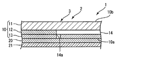
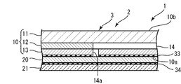
- FIG. 1 is a cross-sectional view of the microfluidic device according to the first embodiment.
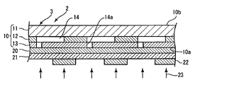
- FIG. 2 is a cross-sectional view of the microfluidic device according to the second embodiment.
- FIG. 3 is a cross-sectional view of the microfluidic device according to the third embodiment.
- FIG. 4 is a cross-sectional view of the microfluidic device according to the fourth embodiment.
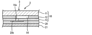
- FIG. 5 is a cross-sectional view of a microfluidic device according to a fifth embodiment.
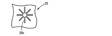
- FIG. 6 is a plan view of a gas generation layer in the fifth embodiment.
- FIG. 7 is a plan view of a gas generation layer in the first modification.
- FIG. 8 is a cross-sectional view of the microfluidic device according to the second modification.
- FIG. 1 is a cross-sectional view of the microfluidic device according to the first embodiment.
- FIG. 2 is a cross-sectional view of the microfluidic device according to the second embodiment.
- FIG. 9 is a plan view of the substrate in the second modification.
- FIG. 10 is a schematic cross-sectional view of a microfluidic device according to Modification 3.
- FIG. 11 is a schematic plan view illustrating the configuration of the microchannel according to the third modification.
- FIG. 12 is a schematic plan view illustrating the configuration of the microchannel according to the fourth modification.
- FIG. 13 is a schematic plan view illustrating the configuration of the microchannel according to the fifth modification.
- FIG. 14 is a schematic plan view illustrating the configuration of the microchannel according to the sixth modification.
- FIG. 15 is a schematic plan view illustrating the configuration of the microchannel according to the seventh modification.
- FIG. 16 is a schematic plan view illustrating the configuration of the microchannel according to Modification 8.
- FIG. 11 is a schematic plan view illustrating the configuration of the microchannel according to the third modification.
- FIG. 12 is a schematic plan view illustrating the configuration of the microchannel according to the fourth modification.
- FIG. 13 is a schematic plan view
- FIG. 17 is a schematic plan view illustrating the configuration of the microchannel according to the ninth modification.
- FIG. 18 is a schematic plan view illustrating the configuration of the microchannel according to the tenth modification.
- FIG. 19 is a schematic plan view illustrating the configuration of the microchannel according to the eleventh modification.
- FIG. 20 is a schematic plan view of the microfluidic device according to the eleventh modification.
- FIG. 21 is a schematic plan view illustrating the configuration of the microchannel according to Modification 12.
- FIG. 22 is a schematic plan view of a microfluidic device according to Modification 12.
- FIG. 23 is a cross-sectional view of a microfluidic device according to Modification Example 13.
- FIG. 24 is a cross-sectional view of a microfluidic device according to Modification Example 14.
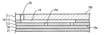
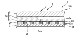
- FIG. 1 is a cross-sectional view of the microfluidic device 1.
- the microfluidic device 1 is not particularly limited as long as it is a device having a microchannel.
- the microfluidic device 1 may be, for example, a microanalysis device for performing heavy metal analysis or biochemical analysis.
- the microfluidic device 1 may further include a detection unit and an analysis unit formed on the substrate 10 in communication with the microchannel 14.
- microchannel means that the liquid flowing through the microchannel is strongly affected by the surface tension and the capillary phenomenon, and behaves differently from the liquid flowing through a channel having a normal size. It refers to a channel formed in a shape and dimension. That is, the “micro flow channel” refers to a flow channel formed in a shape and dimension in which a so-called micro effect appears in the liquid flowing through the micro flow channel.
- the shape and dimension of the flow path in which the micro effect is manifested depends on the physical properties of the liquid introduced into the flow path.
- the smaller of the height and width in the cross section of the microchannel is 5 mm or less, preferably 500 ⁇ m or less, more preferably 200 ⁇ m.
- the diameter of the microchannel is generally set to 5 mm or less, preferably 500 ⁇ m or less, and more preferably 200 ⁇ m or less.
- the microfluidic device 1 includes a micropump system 2.
- a gas generator 3 is formed in the micropump system 2.
- the gas generation unit 3 includes a substrate 10, a gas generation layer 20, and a barrier layer 21.
- the substrate 10 includes a first main surface 10a and a second main surface 10b.
- the first main surface 10a does not include the inner peripheral surface of the opening 14a. That is, the main surface does not include the surface of the recess when the recess is formed on the surface.
- a microchannel 14 is formed on the substrate 10.
- the microchannel 14 is open to the first main surface 10 a of the substrate 10.
- the microchannel 14 is formed with an opening 14a that opens to the first main surface 10a.
- the microchannel 14 may be open on both the first main surface 10a and the second main surface 10b.
- the material of the substrate 10 is not particularly limited.
- the substrate 10 may be made of glass or resin, for example.
- the substrate 10 may be made of, for example, an organosiloxane compound.
- Specific examples of the organic siloxane compound include polydimethylsiloxane (PDMS: poly (dimethylsiloxane)), polymethylhydrogensiloxane, and the like.
- the substrate 10 is substantially made of PDMS. Since the member made of PDMS has high transferability, the substrate 10 with high shape accuracy can be manufactured by using PDMS. Moreover, since PDMS is excellent in light transmittance, the board
- the substrate 10 includes a first substrate 11, a second substrate 12, and a third substrate 13.
- the substrate 10 may be constituted by a single substrate or may be constituted by two or more substrates.
- the first main surface 10a of the substrate 10 is preferably anchored.
- gas is generated between the substrate 10 and the gas generating layer 20, or the generated gas is between the substrate 10 and the gas generating layer 20. It can suppress that it collects in.
- the anchor process examples include a process of applying a corona discharge process or a surface treatment agent to the first main surface 10a of the substrate 10.
- a surface treatment agent for example, urethane resin, (meth) acrylic acid ester copolymer, polymerized or copolymerized polymer containing 1,3 conjugated diene monomer, polymerized oligomer containing 1,3 conjugated diene monomer or Examples thereof include a copolymer oligomer, a polymer or copolymer containing a 1,3-conjugated diene monomer derivative, a polymer oligomer or copolymer oligomer containing a 1,3-conjugated diene monomer derivative, or a mixture thereof.
- the gas generation layer 20 is disposed on the first main surface 10 a of the substrate 10. In the present embodiment, the gas generation layer 20 is attached to the substrate 10. The opening 14 a is covered with the gas generation layer 20.
- the thickness of the gas generating layer 20 is preferably 1 ⁇ m to 200 ⁇ m, more preferably 5 ⁇ m to 100 ⁇ m, and still more preferably 10 ⁇ m to 50 ⁇ m.
- the thickness of the gas generation layer 20 is 1 ⁇ m or less, the amount of gas generated by external stimulation is small, or when the binder resin contains an adhesive resin, the adhesion to the substrate 10 is high. It may be insufficient. Further, when the thickness of the gas generation layer 20 is 200 ⁇ m or more, the time required for the generated gas to reach the substrate 10 tends to be long.
- the gas generation layer 20 is a layer that generates gas by receiving an external stimulus.
- the gas generating layer 20 includes at least a gas generating agent that generates gas by receiving an external stimulus.
- the gas generating layer 20 includes a gas generating agent and a binder.
- the gas generation layer 20 may further contain various additives.
- the external stimulus means a physical or chemical stimulus supplied from the outside in order to cause a gas generation reaction in the gas generation unit.
- the external stimulus acts on the gas generation unit so that gas is generated from the gas generation unit.
- Specific examples of the external stimulus include energy such as light and heat, and substances such as acid and base. That is, “receiving an external stimulus” includes irradiating energy such as light and heat and supplying a substance such as an acid or a base.
- the external stimulus is not particularly limited as long as it causes a gas generating reaction in the gas generating part, but is preferably light. Since on / off of light irradiation and intensity adjustment of light to be irradiated can be easily performed, when the external stimulus is light, control of gas generation is easy, and high response of gas generation is easily obtained. Furthermore, when the external stimulus is light, the thermal durability required for the substrate 10 is reduced, and the degree of freedom in selecting the substrate 10 is improved.
- the gas generating agent may be composed only of a material that generates gas by receiving an external stimulus.
- the gas generating agent includes a stimulus generating agent that generates another stimulus by receiving an external stimulus and a stimulating gas generating agent that generates a gas by receiving a stimulus generated by the stimulus generating agent. Also good.
- the gas generating agent may include, for example, a material that generates acid or alkali by receiving light or heat, and a material that generates gas by acid or alkali generated by the material. More specifically, the gas generating material may contain a photoacid generator that generates acid when irradiated with light, and an acid-stimulated gas generator that generates gas when in contact with acid. . In addition, the gas generating material may include a photobase generator that generates a base when irradiated with light and a base proliferating agent that generates a base gas when contacted with the base.
- the light applied to the gas generating layer 20 is not particularly limited as long as it is light in a wavelength band that is absorbed by the gas generating agent or sensitizer, but the wavelength is 10 nm to 400 nm, and the wavelength is 400 nm to 420 nm, which is close to the ultraviolet light. It is preferably light, and more preferably near ultraviolet light having a wavelength of 300 nm to 400 nm.
- the light source used for light irradiation to the gas generation layer 20 is not particularly limited.
- the light source include, for example, a low-pressure mercury lamp, a medium-pressure mercury lamp, a high-pressure mercury lamp, an ultrahigh-pressure mercury lamp, a light emitting diode (LED), an all-solid-state laser, a chemical lamp, a black light lamp, a microwave-excited mercury lamp, a metal halide lamp, and a sodium lamp.
- Halogen lamps, xenon lamps, fluorescent lamps and the like as the light source, a light emitting element such as a light emitting diode (LED) that generates little heat and is inexpensive is preferably used.
- LED light emitting diode
- gas generating agent examples include azo compounds and azide compounds.
- the azo compound may be an azoamide compound.
- the azo compound include, for example, 2,2′-azobis (N-cyclohexyl-2-methylpropionamide), 2,2′-azobis [N- (2-methylpropyl) -2-methylpropionamide].
- the azide compound examples include 3-azidomethyl-3-methyloxetane, terephthalazide, a polymer having an azide group, and the like.
- the polymer having an azide group examples include glycidyl azide polymer.
- the glycidyl azide polymer can be obtained, for example, by ring-opening polymerization of p-tert-butylbenzazide and 3-azidomethyl-3-methyloxetane.
- These azide compounds are decomposed by being stimulated by light in a specific wavelength range, heat, ultrasonic waves, impact, and the like to generate nitrogen gas.
- azo compounds are extremely easy to handle because they do not generate gas upon impact. Further, the azo compound does not cause a chain reaction and explosively generate a gas, but can interrupt the generation of gas by interrupting the irradiation of light. For this reason, control of gas generation amount becomes easy by using an azo compound as a gas generating agent.
- the gas generating agent such as an azo compound preferably has high heat resistance.
- the 10-hour half-life temperature of the gas generating agent is preferably 80 ° C. or higher.
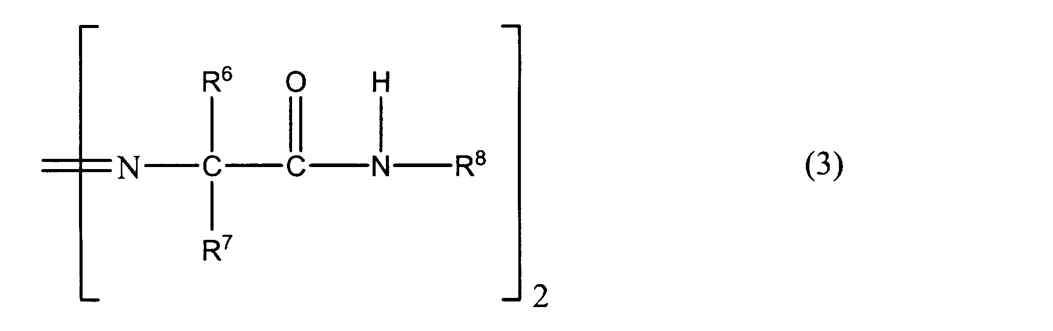
- Examples of the azo compound having a 10-hour half-life temperature of 80 ° C. or higher include an azoamide compound represented by the following general formula (3).
- the azoamide compound represented by the following general formula (3) is excellent in solubility in an adhesive polymer such as an alkyl acrylate polymer in addition to excellent heat resistance. For this reason, it can suppress that an azoamide compound makes particles in adhesive agent resin.
- R 6 and R 7 each independently represent a lower alkyl group, and R 8 represents a saturated alkyl group having 2 or more carbon atoms. R 6 and R 7 may be the same or different.
- azoamide compound represented by the general formula (3) examples include, for example, 2,2′-azobis (N-cyclohexyl-2-methylpropionamide), 2,2′-azobis [N- (2- Methylpropyl) -2-methylpropionamide], 2,2′-azobis (N-butyl-2-methylpropionamide), 2,2′-azobis [N- (2-methylethyl) -2-methylpropionamide ], 2,2'-azobis (N-hexyl-2-methylpropionamide), 2,2'-azobis (N-propyl-2-methylpropionamide), 2,2'-azobis (N-ethyl-2) -Methylpropionamide), 2,2′-azobis ⁇ 2-methyl-N- [1,1-bis (hydroxymethyl) -2-hydroxyethyl] propionamide ⁇ , 2,2 -Azobis ⁇ 2-methyl-N- [2- (1-hydroxybutyl)] propionamide ⁇ , 2,2'-azobis [2-methyl-N-N-
- 2,2′-azobis (N-butyl-2-methylpropionamide) and 2,2′-azobis [N- (2-propenyl) -2-methylpropionamide] have improved solubility in solvents. It is preferably used because it is particularly excellent.
- the photoacid generator is not particularly limited.
- As the photoacid generator for example, a conventionally known photoacid generator can be used.
- the photoacid generator it is preferable to use at least one selected from the group consisting of quinonediazide compounds, onium salts, sulfonic acid esters and organic halogen compounds, and sulfonic acid onium salts, benzylsulfonic acid esters, halogenated isocyanates are preferable. It is more preferable to use at least one selected from the group consisting of nurate and bisarylsulfonyldiazomethane. These photoacid generators are efficiently decomposed by light irradiation to generate a strong acid such as sulfonic acid. Therefore, the gas generation efficiency can be further enhanced by using these photoacid generators.
- Examples of the quinonediazide compound include esters of 1,2-naphthoquinone-2-diazide-5-sulfonic acid or 1,2-naphthoquinone-2-diazide-4-sulfonic acid and a low-molecular aromatic hydroquinone compound.
- Examples of the low molecular aromatic hydroquinone compound include 1,3,5-trihydroxybenzene, 2,3,4-trihydroxybenzophenone, 2,3,4,4'-tetrahydroxybenzophenone, cresol and the like.
- 1,2-naphthoquinone-2-diazide-5-sulfonic acid-p-cresol ester is particularly preferably used.
- onium salts include triphenylsulfonium hexafluoroantimonate and triphenylsulfonium hexafluorophosphate.
- sulfonate esters examples include bisarylsulfonyldiazomethane, p-nitrobenzyl 9,10-dimethoxyanthracene-2-sulfonate, m-nitrobenzyl 9,10-dimethoxyanthracene-2-sulfonate, m, p-dinitrobenzyl 9, 10-dimethoxyanthracene-2-sulfonate, p-cyanobenzyl 9,10-dimethoxyanthracene-2-sulfonate, chlorobenzyl 9,10-dimethoxyanthracene-2-sulfonate, dimethylaminonaphthalene-5-sulfonate, diphenyliodonium-9, 10-dimethoxyanthracene-2-sulfonate, 4-methoxyphenyl-phenyliodonium-9,10-dimethoxyanthracene-2-sulfonate, bis (4-methoxyphenyl
- organic halogen compound examples include tribromomethylphenylsulfone, tribromomethylsulfonylpyridine, and the like.
- the acid stimulating gas generator is not particularly limited as long as it generates gas by acid stimulation, that is, by the action of an acid, but at least one of carbonate and bicarbonate is preferably used.
- the acid stimulating gas generating agent examples include sodium hydrogen carbonate, sodium carbonate, sesqui sodium carbonate, magnesium carbonate, potassium carbonate, potassium hydrogen carbonate, calcium carbonate, sodium borohydride and the like. These acid stimulating gas generating agents may be used alone or in combination of two or more. Sodium bicarbonate and sodium carbonate are preferable, and a mixture of sodium carbonate and sodium hydrogen carbonate is preferably used as an acid-stimulating gas generating agent because of its excellent stability and a large amount of gas generation. .
- the compounding amount of the acid stimulating gas generating agent is a chemical equivalent amount to the acid generated from the photo acid generating agent.
- each of the acid stimulating gas generating agent and the photoacid generating agent may be liquid or particulate.
- at least one of the acid-stimulating gas generator and the photoacid generator is a fine particle.
- fine particles mean particles having an average diameter of about 50 ⁇ m to 2 mm.
- the gas generating agent may contain a photobase generator (A) that decomposes by light irradiation to generate a gaseous base and a base proliferating agent (B).
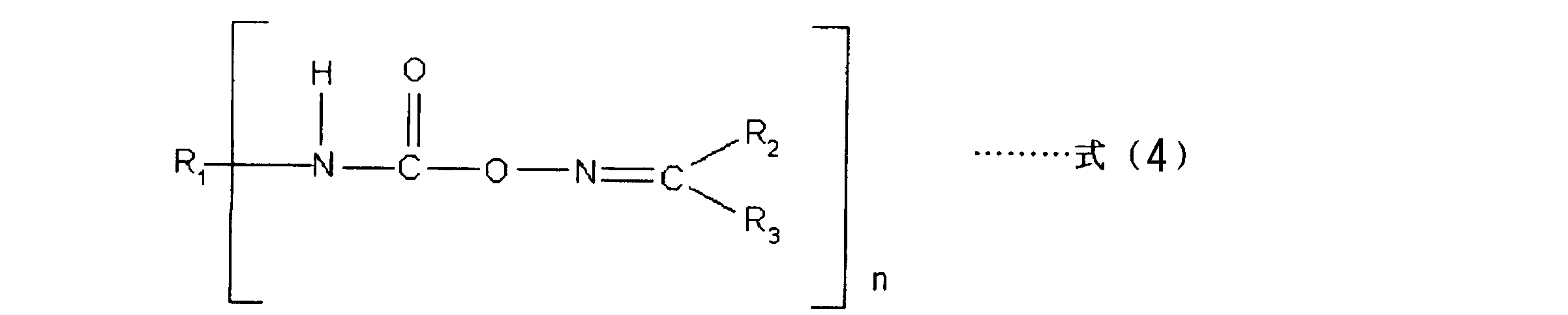
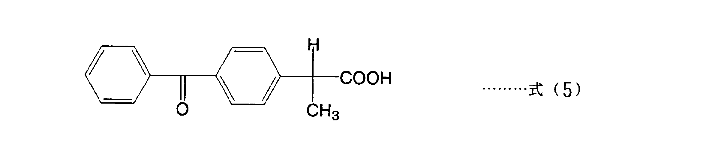
- the photobase generator (A) includes, for example, a cobaltamine complex, o-nitrobenzyl carbamate, oxime ester, a carbamoyloxyimino group-containing compound that generates an amine by irradiation with light represented by the following formula (4), And at least 1 sort (s) selected from the group which consists of a salt of carboxylic acid (a1) represented by following formula (5) and a basic compound (a2) may be sufficient.
- R 1 is an n-valent organic group
- R 2 and R 3 are each hydrogen, aromatic or aliphatic group
- n is an integer of 1 or more.
- the carbamoyloxyimino group-containing compound represented by the above formula (4) is not particularly limited, but examples thereof include compounds shown to be produced as follows in JP-A No. 2002-138076. Can do.
- acetophenone oxime dissolved in 100 ml of tetrahydrofuran (THF) was added to 0.05 mol of hexamethylene diisocyanate, followed by drying and stirring at 50 ° C. for 4 hours in a nitrogen atmosphere.
- THF tetrahydrofuran
- a white solid was obtained.
- the obtained white solid was dissolved in methyl ethyl ketone at 80 ° C., purified by recrystallization, and a compound capable of generating an amine by light irradiation was produced.
- the salt of the carboxylic acid (a1) and the basic compound (a2) can be easily prepared by simply mixing the carboxylic acid (a1) and the basic compound (a2) in a solution.
- an acid-base reaction represented by the following reaction formula (S1) proceeds to produce a salt A1.
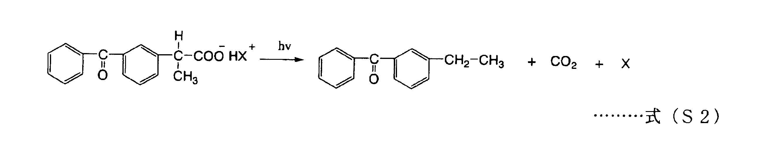
- the salt obtained as described above has a skeleton derived from the carboxylic acid (a1), it is easily decarboxylated by light irradiation, and the reaction represented by the following reaction formula (S2) proceeds. Accordingly, the salt alone exhibits excellent photolysis performance. That is, base gas and carbon dioxide are rapidly generated by the decomposition of the salt, and a sufficient amount of base gas and carbon dioxide are generated.
- X represents a basic compound (a2).
- the basic compound (a2) is not particularly limited.
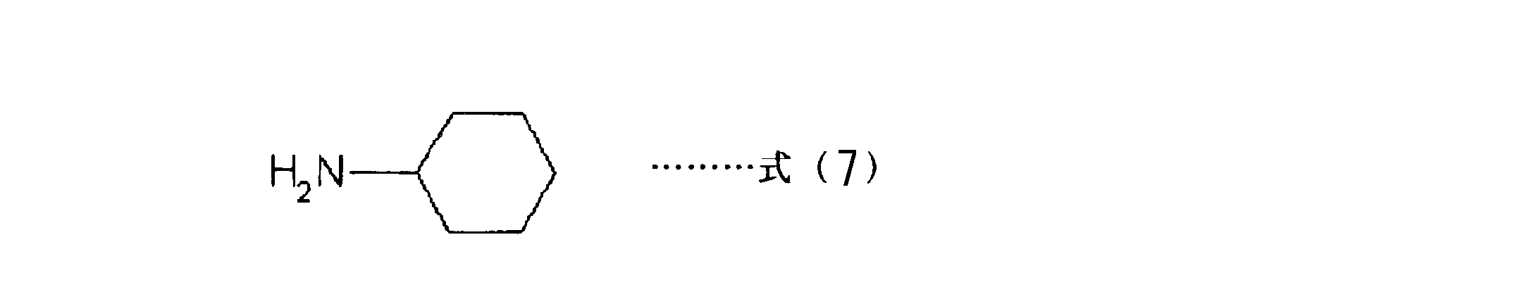
- amines such as primary amines, secondary amines and tertiary amines, compounds containing pyridyl groups, hydrazine compounds, amide compounds, quaternary ammonium hydroxide salts, Mercapto compounds, sulfide compounds, phosphine compounds, and the like can be used. A plurality of these may be used.
- the basic compound (a2) at least one selected from the group consisting of compounds represented by the following formulas (6) to (9) is preferably used.
- the salt decomposes more rapidly by light irradiation, and base gas and carbon dioxide are generated more rapidly.
- R 1 represents an alkylene chain having 1 to 10 carbon atoms. Since base gas is also generated, preferably R 1 is an alkylene chain having 1 to 2 carbon atoms.
- R 2 represents an alkylene chain having 1 to 10 carbon atoms. Since a base gas is also generated, preferably R 2 represents an alkylene chain having 1 to 2 carbon atoms.
- R 1 is an alkylene chain having 3 to 10 carbon atoms in Formula (9) and when R 2 is an alkylene chain having 3 to 10 carbon atoms in Formula (10), the molecular weight is large.
- the base proliferator does not generate base gas. However, since these base proliferating agents contain many carboxyl groups in the side chains, carbon dioxide gas is generated quickly and efficiently.
- the base proliferating agent is not particularly limited, but preferably a 9-fluorenyl carbamate derivative is used.
- the 9-fluorenyl carbamate derivative may be any of a bifunctional type, a spherical polyfunctional oligomer type, a linear polymer type, or a siloxane type.
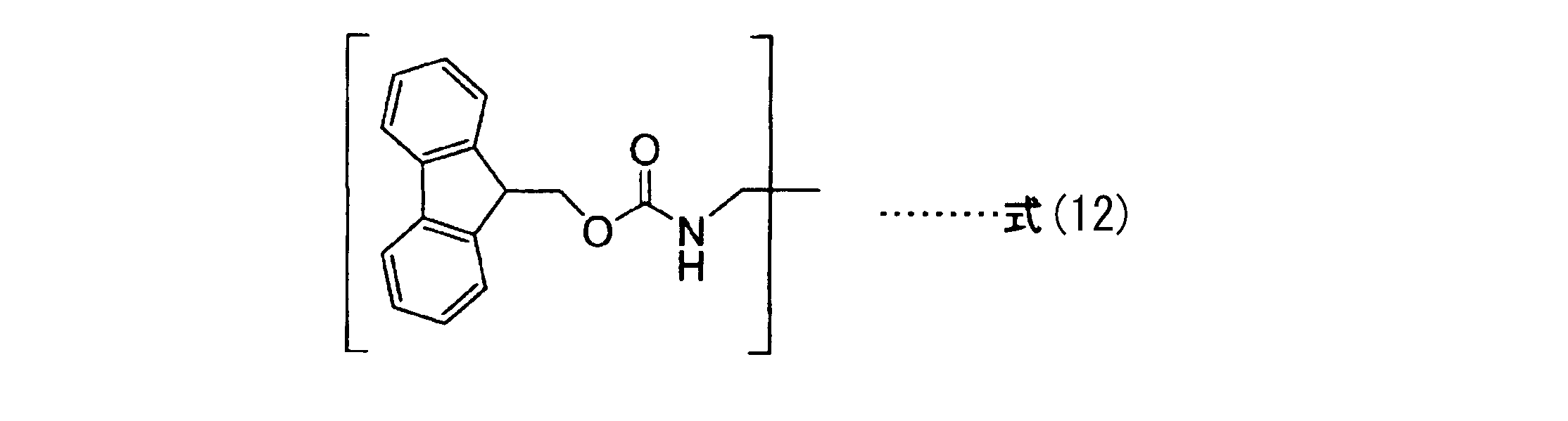
- a base proliferating agent (B1) having a base proliferating group represented by the following formula (12) is preferable.
- the base proliferating agent (B1) having a base proliferating group represented by the above formula (12) is decomposed by a base proliferating reaction to newly generate an amine. Furthermore, the generated amine functions as a new catalyst, and a large number of amines are produced in a proliferative manner.
- the more base proliferating groups represented by the above formula (12) are present in the molecule the more efficiently the base proliferating reaction in the molecule occurs. Therefore, even more amino groups are generated.
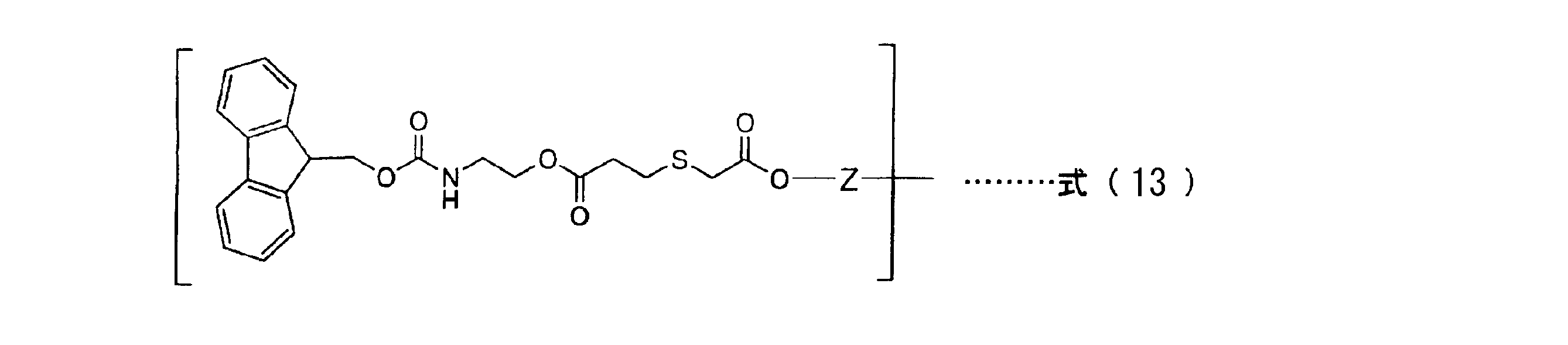
- the base proliferating group represented by the above formula (12) is preferably a base proliferating group represented by the following formula (13).
- Z represents a substituted or unsubstituted alkylene chain.
- Z examples include methylene chain, ethylene chain, propylene chain and the like.
- Z is preferably an unsubstituted alkylene chain because the above-described base growth reaction occurs effectively. Among them, it is more preferable that Z is a methylene chain because the steric hindrance in Z is reduced and the base growth reaction is more likely to occur more effectively.
- a base proliferating agent having a base proliferating group represented by the above formula (13) As the base proliferating agent having a base proliferating group represented by the above formula (13), a base proliferating agent represented by the following formula (14) is preferable.
- X represents a hydrogen atom, a substituted alkyl group, or an unsubstituted alkyl group
- Z represents a substituted or unsubstituted alkylene chain
- n represents an integer of 1 to 4.
- X examples include a methyl group, an ethyl group, and a propyl group.
- X is preferably an unsubstituted alkyl group because a base proliferating reaction occurs effectively. Especially, since the steric hindrance in X becomes small and the base proliferation reaction is more likely to occur, X is more preferably an ethyl group.
- n represents an integer of 1 to 4.
- the base proliferating agent represented by the above formula (14) has a plurality of 9-fluorenyl carbamate groups in the same molecule, the base proliferating reaction is more likely to occur more effectively by the catalytic action of the generated base. . Therefore, in the above formula (14), n is preferably an integer of 3 or 4.
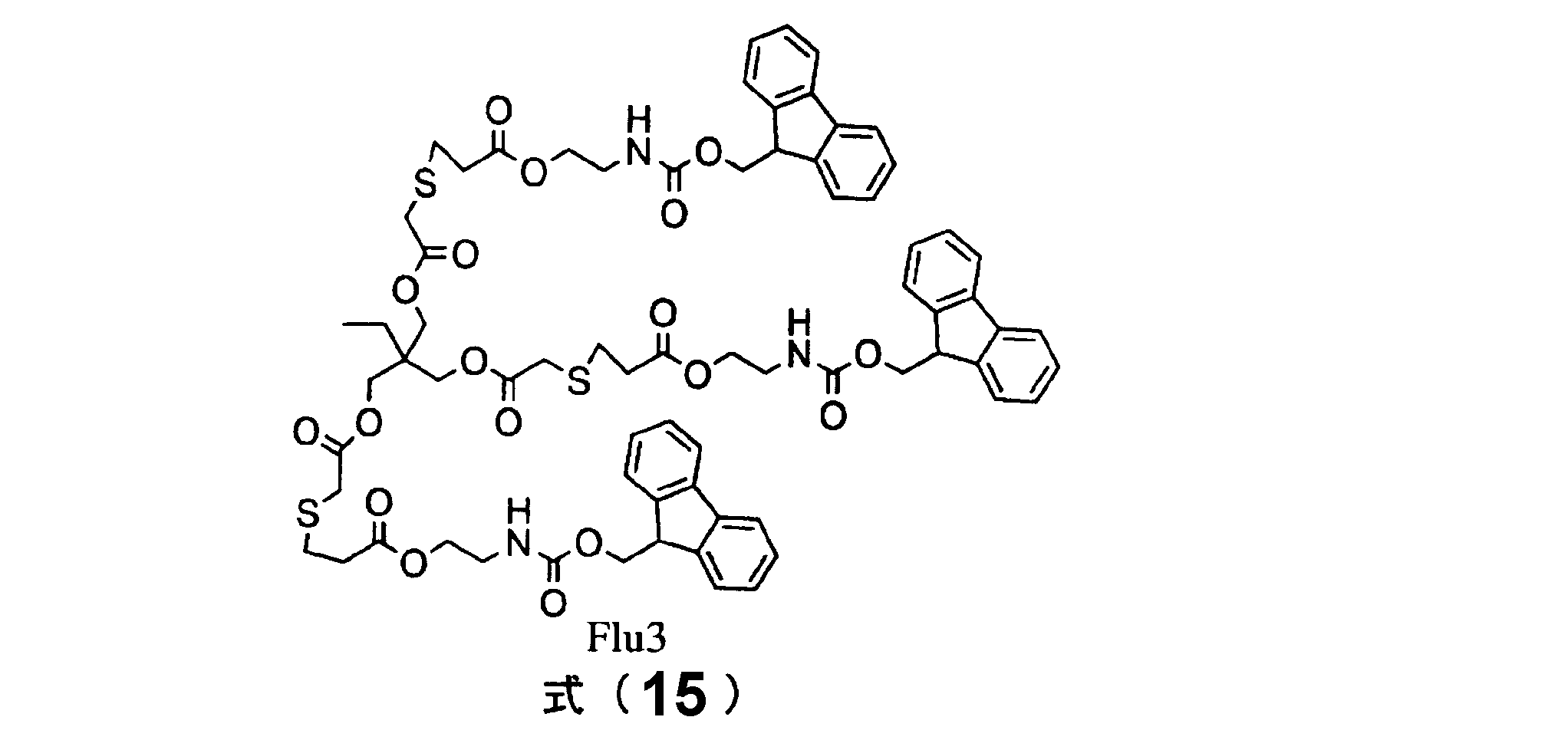
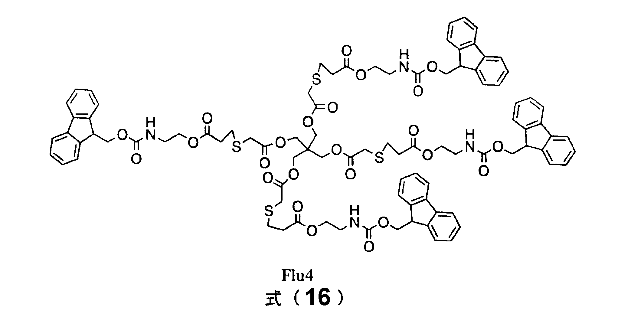
- base proliferating agent represented by the above formula (14) examples include a base proliferating agent (Flu3) represented by the following formula (15) and a base proliferating agent (Flu4) represented by the following formula (16). Can be mentioned.
- the base proliferating agent represented by the following formula (15) and formula (16) can be obtained by a known method.
- the base proliferating agent represented by the above formulas (15) and (16) has a plurality of 9-fluorenyl carbamate groups in the same molecule. Therefore, the base proliferation reaction is likely to proceed due to the catalytic action of the generated base. Since the base generation efficiency is further enhanced, the base proliferating agent represented by the above formula (15) is more preferable, and the base proliferating agent represented by the above formula (16) is more preferable.
- the base proliferating agent having a base proliferating group represented by the above formulas (12) and (13) or the base proliferating agent represented by the above formulas (14) to (16) is not particularly limited. It can be synthesized by an addition reaction between nilmethanol and an isocyanate derivative, or an addition reaction between an acrylate monomer having a fluorenyl carbamate group and a polythiol derivative. By appropriately using a tin catalyst for the former addition reaction and appropriately using a base catalyst for the latter addition reaction, the synthesis can be carried out simply.
- a base proliferating group represented by the above formula (12) As the base proliferating group represented by the above formula (12), a base proliferating group represented by the following formula (17) is also preferable.
- R shows a hydrogen atom or a methyl group.
- the base proliferating agent (B1) having a base proliferating group represented by the above formula (12) includes a base proliferating group represented by the above formula (17) and an unsaturated group represented by the following formula (18).
- a base proliferating agent having a group can also be used more preferably.
- R shows a hydrogen atom or a methyl group.
- a base proliferating agent having a base proliferating group represented by the above formula (17) and an unsaturated group represented by the above formula (18) can also be used more preferably.
- the base proliferating agent having a base proliferating group represented by the above formula (17) includes, for example, a compound having an unsaturated group represented by the above formula (18) as shown in the following reaction formula (X2): It can be obtained by addition reaction with 9-fluorenylmethyl N- (2-mercaptoethyl) carbamate.
- R in the above formula (17) is derived from R of the unsaturated group represented by the above formula (18).
- R represents a hydrogen atom or a methyl group.
- the compound having an unsaturated group represented by the above formula (18) is a compound having an acrylate group or a methacrylate group (hereinafter referred to as “(meth) acrylate group”).
- a (meth) acrylate monomer or oligomer can be used as the compound having an unsaturated group represented by the above formula (18).
- a (meth) acrylate monomer or oligomer can be used.
- Monomer having at least two (meth) acrylate groups since the base proliferating reaction occurs efficiently when the base proliferating agent contains as many base proliferating groups represented by the above formula (18) in the same molecule as much as possible.
- an oligomer is preferable.
- polyfunctional (meth) acrylate monomer or (meth) acrylate oligomer examples include ethylene di (meth) acrylate, triethylene glycol di (meth) acrylate, epoxy acrylate, and the like.
- a novolak type compound or a known dendritic polyfunctional (meth) acrylate can also be used. These may be used alone or as a mixture.
- the compound having at least two unsaturated groups represented by the above formula (18) is obtained by, for example, subjecting a compound having an unsaturated group represented by the above formula (18) to Michael addition reaction of ⁇ -thioglycerin, It can be obtained by converting into a diol-substituted group represented by the following formula (19) and then esterifying or urethanizing each hydroxyl group. By this reaction, for example, one unsaturated group can be converted into two or four unsaturated groups.
- R represents a hydrogen atom or a methyl group.
- the blending ratio of the base proliferating agent (B) is preferably in the range of 20 to 300 parts by weight with respect to 100 parts by weight of the basic compound (A). If the base proliferating agent (B) is less than 20 parts by weight, the chain reaction using the base proliferating agent reaction may not occur efficiently. If it exceeds 300 parts by weight, the base proliferating agent may be saturated in the solvent, and the base proliferating agent may be precipitated. In addition, a chain reaction dominates the reaction system, and when the reaction is desired to be stopped, it cannot be stopped, and the control of the reaction may be difficult.
- Aminoalkyl compound (C) It is preferable that the aminoalkyl compound (C) is further contained at a ratio of 20 to 100 parts by weight with respect to 100 parts by weight of the photobase generator (A). If the amount is less than 20 parts by weight, the effect of adding the aminoalkyl compound (C) may not be sufficiently obtained. If the amount exceeds 100 parts by weight, the radical generated from the photobase generator is equivalent to the photobase generator, Even if it is added excessively, the reaction may be completed without being reacted.
- the aminoalkyl compound (C) reacts with an alkyl radical generated by the decomposition of the photobase generator (A). This reaction also generates base gas. Therefore, the gas generation efficiency is further enhanced.
- the generated base gas further reacts with the base proliferating agent (B), so that the base gas is generated more geometrically. Furthermore, carbon dioxide is generated at the same time when the base gas is generated. Therefore, in addition to the base proliferating agent (B), by further using the aminoalkyl compound (C), the gas generation efficiency can be further enhanced.
- the aminoalkyl compound (C) is not particularly limited, and is selected from methylamine, ethylamine, butylamine, N-methyl-aminoethyl, N, N-dimethylaminoethyl, N, N-diethylethylenediamine and N-methylaminobutyl.
- One kind of compound selected from the group consisting of is preferably used, and in this case, the gas generation efficiency can be further increased.
- the gas generating agent contains the photobase generating agent (A)
- a sufficient amount of base gas can be generated even when a small amount of light is irradiated for a short time even if it does not contain a photosensitizer.
- the gas generating layer 20 preferably further contains a photosensitizer.
- a photosensitizer By including a photosensitizer in the gas generation layer 20, gas can be generated more rapidly when light is irradiated.
- the photosensitizer is not particularly limited as long as it is a compound that promotes the decomposition of the gas generating agent by transferring energy to the gas generating agent that generates gas when irradiated with light.
- the photosensitizer include thioxanthone, benzophenone, acetophenones, Michler's ketone, benzyl, benzoin, benzoin ether, benzyldimethyl ketal, benzoyl benzoate, ⁇ -acyloxime ester, tetramethylthiuram monosulfide, aliphatic amine, aromatic Amines containing aromatic groups, those in which nitrogen is part of the ring system such as piperidine, allylthiourea, o-tolylthiourea, sodium diethyldithiophosphate, soluble salts of aromatic sulfinic acids, N, N-disubstituted -P-aminobenzonitrile compounds, tri-n-buty
- the blending ratio of the photosensitizer is not particularly limited as long as the photosensitizing action is obtained.
- the photosensitizer is added to 100 parts by weight of the gas generating agent that generates gas when irradiated with light.
- the content is preferably 0.1 to 50 parts by weight, more preferably 1 to 10 parts by weight. If the amount of photosensitizer is too small, sufficient sensitizing action tends to be difficult to obtain. If the amount of photosensitizer is too large, photodecomposition of the gas generating agent may be suppressed.
- a photodegradable azo compound or a peroxide may be added to the gas generation layer 20 for the purpose of assisting gas generation.
- photodegradable azo compound examples include azoamide compounds, azonitrile compounds, azoamidine compounds, and cyclic azoamidine compounds. These azo compounds may be used alone or in combination of two or more.
- photodegradable peroxide examples include benzoyl peroxide, di-t-butyl peroxide, isoamyl o-dimethylaminobenzoate, anthraquinones, triazines, azobisisobutyronitrile, benzoyl peroxide, cumeneper And oxides.
- anthraquinones examples include 2-ethylanthraquinone, octamethylanthraquinone, 1,2-benzanthraquinone, 2,3-diphenylanthraquinone and the like.
- triazines examples include 2,4-trichloromethyl- (4′-methoxyphenyl) -6-triazine, 2,4-trichloromethyl- (4′-methoxynaphthyl) -6-triazine, and 2,4-trichloro. Examples thereof include methyl- (piperonyl) -6-triazine, 2,4-trichloromethyl- (4′-methoxystyryl) -6-triazine and the like.
- a radical scavenger or the like may be added to the gas generation layer 20.
- radical scavengers examples include t-butylcatechol, hydroquinone, methyl ether, catalase, glutathione peroxidase, superoxide dismutase enzyme vitamin C, vitamin E, polyphenols, and linolenic acid.
- the gas generating agent is preferably present as a compatibilized state in the gas generating layer 20. This is because high gas generation efficiency can be obtained and the smoothness of the surface of the gas generation layer 20 can be increased.
- the “compatibility state” means a state in which the gas generating agent is finely dispersed or compatible so that the gas generating agent cannot be confirmed when the gas generating layer 20 is observed with an electron microscope.
- a gas generating agent that dissolves in the gas generating layer 20 so that the gas generating agent exists in a compatibilized state.
- the gas generating agent may be difficult to dissolve in the gas generating layer 20.
- distribute a gas generating agent for example using a disperser or using a dispersing agent together.
- binder resin for example, polymer materials such as poly (meth) acrylate, polyester, polyethylene, polypropylene, polystyrene, polyether, polyurethane, polycarbonate, polyamide, polyimide and the like can be used. Moreover, these copolymers may be used and these may be used together. Of these, poly (meth) acrylate is preferred because the gas generation efficiency is further enhanced.
- the ultraviolet light absorption band of the binder resin is preferably shorter than the ultraviolet light absorption band of the photoacid generator, photosensitizer, or photobase generator.
- the binder resin is added to give the gas generating layer 20 various functions.
- the binder resin preferably contains, for example, an adhesive resin.
- an adhesive resin By making the gas generating layer 20 contain an adhesive resin as a binder resin, it is possible to improve the adhesiveness and adhesiveness between the gas generating layer 20 and the substrate 10.
- the adhesive resin is not cured by an external stimulus applied to the gas generation layer 20. Maintaining high adhesiveness between the gas generation layer 20 and the substrate 10 even after the application of external stimulation to the gas generation layer 20 is started by making the adhesive resin not cured by external stimulation. Because you can.
- the adhesive resin is preferably one that is not crosslinked by an external stimulus, for example.
- the adhesive resin include, for example, rubber-based adhesive resin, acrylic adhesive resin, silicone-based adhesive resin, urethane-based adhesive resin, styrene-isoprene-styrene.
- examples thereof include copolymer-based adhesive resins, styrene-butadiene-styrene copolymer adhesive resins, epoxy-based adhesive resins, and isocyanate-based adhesive resins.
- an acrylic adhesive resin is used.
- the binder resin does not need to contain the adhesive resin.
- the binder resin adhesive agent resin as shown in FIG. 23, between the substrate 10 and the gas generating layer 20 and between the gas generating layer 20 and the barrier layer 21. You may affix the board
- the form of the gas generating layer is not limited to the gas generating film.
- the gas generating layer may be, for example, a plate-like or film-like porous body to which a gas generating agent is attached or impregnated.
- the gas generated in the gas generation layer is promptly guided to the microchannel through a large number of holes formed in the porous body. Therefore, the liquid feeding efficiency of the microfluidic system can be further increased.
- the porous body is not particularly limited, and specific examples include, for example, a nonwoven fabric, a woven fabric, and a foam that are an aggregate of a plurality of fibers.
- the gas generation layer is preferably processed into a shape in which gas is easily supplied to the microchannel so that the gas generated in the gas generation layer is quickly supplied to the microchannel.
- the gas generation layer 20 may have a plurality of through holes 35 penetrating the gas generation layer 20 in the thickness direction of the gas generation layer 20 in a matrix.
- the diameter of the through hole 35 is preferably smaller than the diameter of the microchannel 14.
- the azo compound or the azide compound is preferably contained in a proportion of 5 to 100 parts by weight, more preferably 10 to 50 parts by weight with respect to 100 parts by weight of the binder resin. Parts by weight. If the ratio of azo compound or azide compound is too small, the amount of gas generated by external stimulation may be too small. If the ratio of azo compound or azide compound is too large, the azo compound or azide compound can be dissolved in the binder resin. It may disappear.
- the above-mentioned photoacid generator is preferably contained in a proportion of 2 to 150 parts by weight, more preferably 10 to 100 parts by weight with respect to 100 parts by weight of the binder resin.
- the acid stimulating gas generating agent is preferably contained in a proportion of 2 to 150 parts by weight, more preferably 10 to 100 parts by weight, with respect to 100 parts by weight of the binder resin. If the ratio of photoacid generator and acid-stimulated gas generator is too small, gas generation due to light irradiation may not be sufficient. If the ratio of photoacid generator and acid-stimulated gas generator is too large, photoacid generation will occur. In some cases, the agent and the acid stimulating gas generating agent cannot be dissolved in the binder resin.
- the photobase generator is preferably contained in a proportion of 20 to 500 parts by weight per 100 parts by weight with respect to 100 parts by weight of the binder resin. If the ratio of the photobase generator is too small, gas generation due to light irradiation may not be sufficient, and if the ratio of the photobase generator is too large, the photobase generator cannot be dissolved in the binder resin. There is.
- the mixing ratio of the base proliferating agent is preferably in the range of 20 to 300 parts by weight with respect to 100 parts by weight of the photobase generator. If the base proliferating agent is less than 20 parts by weight, the chain reaction using the base proliferating agent reaction may not occur efficiently. If it exceeds 300 parts by weight, the base proliferating agent may be saturated in the solvent, and the base proliferating agent may be precipitated. In addition, a chain reaction dominates the reaction system, and when the reaction is desired to be stopped, it cannot be stopped, and the control of the reaction may be difficult.
- the compounding ratio of the aminoalkyl compound is preferably in the range of 20 to 100 parts by weight with respect to 100 parts by weight of the photobase generator. When the compounding ratio of the aminoalkyl compound is less than 20 parts by weight, the effect of adding the aminoalkyl compound may not be sufficiently obtained. When the compounding ratio of the aminoalkyl compound exceeds 100 parts by weight, radicals generated from the photobase generator are The amount of the photobase generator is the same as that of the photobase generator.
- the acrylic adhesive resin is a polymer that has adhesiveness at room temperature.
- the acrylic adhesive resin is, for example, an acrylic acid alkyl ester and a methacrylic acid in which the carbon number of the alkyl group as the main monomer is usually in the range of 2-18. It can be obtained by copolymerizing at least one of the alkyl esters, a functional group-containing monomer, and another modifying monomer that can be copolymerized as necessary, by a conventional method.
- the weight average molecular weight of the functional group-containing (meth) acrylic polymer is usually about 200,000 to 2,000,000.
- the polarity of the substrate 10 is low, as in the case where the substrate 10 is substantially made of an organosiloxane compound, it is preferable to use an adhesive resin having a low polarity.
- the adhesive strength between the substrate 10 and the gas generation layer 20 can be increased even when the polarity of the substrate 10 is low by using the adhesive resin having a low polarity.
- low-adhesive adhesive resin examples include an adhesive resin having a side chain with a low polarity such as an alkyl pendant compound and a fluorine-substituted alkyl pendant compound, and a silicone-based adhesive resin.
- alkyl pendant compound examples include a long-chain alkyl acrylate polymer and a long-chain alkyl-modified polymer.
- the long-chain alkyl acrylate polymer include, for example, a long-chain alkyl acrylate having 12 or more carbon atoms, such as stearyl acrylate, butyl acrylate or acrylonitrile as a film forming component, and adhesion to a tape support.
- examples include those obtained by copolymerizing acrylic acid or maleic anhydride as a functional group component.
- long-chain alkyl-modified polymer examples include those obtained by pendating a long-chain alkyl component such as alkyloyl chloride or alkyl isocyanate with respect to a polymer having a high degree of polymerization such as polyvinyl alcohol.
- fluorine-substituted alkyl pendant compound examples include (meth) alkyl acrylate containing a CF 3 group or a CH 3 group.
- fluorine-substituted alkyl pendant compound examples include 2,2,2-trifluoroethyl (meth) acrylate and 2,2,3,3-tetrafluoropentyl acrylate, butyl acrylate and acrylonitrile as film forming components, It may be a copolymer of acrylic acid or maleic anhydride as a functional group component that provides adhesion to the tape support.
- silicone-based adhesive resin examples include, for example, a mixture containing silicone rubber and silicone resin.
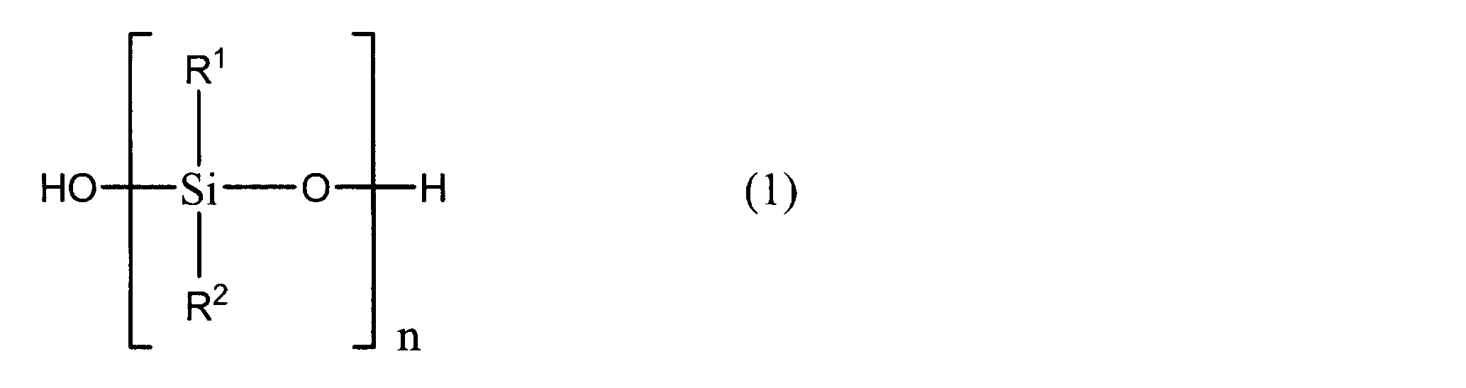
- silicone rubber examples include linear organopolysiloxanes represented by the following formula (1).
- silicone resin examples include a silicone resin represented by the following formula (2).
- each of R 1 and R 2 is a methyl group or a phenyl group, and n is 5,000 to 20,000.
- each of R 3 , R 4 and R 5 is a methyl group or a phenyl group, x is 2,000 to 7,500, and y is 2,300 to 13,500. .
- the silicone rubber may have a crosslinked part.
- the method for crosslinking the silicone rubber is not particularly limited, and examples thereof include a method using a peroxide such as benzoyl peroxide and a method using a hydrosilylation reaction.
- the solubility parameter (SP value) of the silicone-based adhesive resin is not particularly limited, but is preferably 6.0 to 11.0, for example. According to this, the adhesion strength between the substrate 10 having a low polarity and the gas generation layer 20 can be further increased.
- the solubility parameter (SP value) is the square root of the cohesive energy of the substance, and serves as a guideline for the solubility of the resin in the solvent and the compatibility or adhesion between the resins.
- a silane coupling agent may be contained in the adhesive resin.
- the adhesion strength between the substrate 10 having a low polarity and the gas generation layer 20 can be increased.
- the silane coupling agent include, for example, vinylsilane compounds such as vinyltrimethoxysilane and vinyltriethoxysilane, 2- (3,4-epoxycyclohexyl) ethyltrimethoxysilane, and 3-glycidoxypropyltrimethoxysilane.
- Epoxysilane compounds such as 3-methacryloxypropyl ”methyldimethoxysilane, 3-methacryloxypropyltrimethoxysilane and other methacrylosilane compounds, N-2- (aminoethyl) -3-aminopropylmethyldimethoxysilane, N— And aminosilane compounds such as 2- (aminoethyl) -3-aminopropyltrimethoxysilane.
- an adhesion layer may be provided between the substrate 10 and the gas generation layer 20.
- the adhesion strength between the substrate 10 and the gas generation layer 20 can be increased.
- the substrate 10 and the gas generation layer 20 are substantially
- various crosslinking agents that are blended in general pressure-sensitive adhesives such as isocyanate compounds, melamine compounds, and epoxy compounds may be appropriately mixed with the binder resin as desired.
- the gas generation layer 20 may be comprised by the 1 or several film, for example. That is, the gas generation layer 20 may be formed by forming a film on the substrate 10, or the film-like gas generation layer 20 may be attached to the substrate 10.
- the barrier layer 21 is provided on the surface of the gas generating layer 20 opposite to the substrate 10 side.
- the barrier layer 21 is for suppressing the gas generated in the gas generation layer 20 from flowing out to the barrier layer 21 side. For this reason, it is preferable that the barrier layer 21 is hard to permeate the gas generated in the gas generation layer 20, and preferably does not substantially permeate the gas generated in the gas generation layer 20.
- the barrier layer 21 preferably transmits light when the gas generating layer 20 generates gas by light irradiation.
- the barrier layer 21 may be, for example, a resin film, film or substrate, or a glass film, film or substrate.
- the material of the barrier layer 21 include polyacryl, polyolefin, polycarbonate, vinyl chloride resin, ABS resin, polyethylene terephthalate (PET) resin, nylon resin, urethane resin, polyimide resin, and glass.
- the barrier layer 21 may be formed by forming a film on the gas generation layer 20.
- a film-like barrier layer 21 may be stuck on the gas generation layer 20.
- the gas generation layer 20 may be formed on the barrier layer 21 in advance, and then the surface of the gas generation layer 20 opposite to the barrier layer 21 may be attached to the substrate 10.
- the method for forming the gas generating layer 20 is not particularly limited.
- the gas generation layer 20 may be formed by coating or extrusion.
- the surface of the barrier layer 21 on the gas generation layer 20 side is preferably subjected to anchor treatment.
- anchor treatment By performing anchor treatment on the surface of the barrier layer 21 on the gas generation layer 20 side, gas is generated between the barrier layer 21 and the gas generation layer 20, or the generated gas is transferred between the barrier layer 21 and the gas generation layer. It is possible to suppress accumulation in a gap between the two. Therefore, it can suppress that the barrier layer 21 and the gas generation layer 20 peel.
- the anchor processing method the same method as described above can be used.
- the layer thickness of the barrier layer 21 is not particularly limited, but is preferably 10 ⁇ m to 100 ⁇ m, and more preferably 25 ⁇ m to 75 ⁇ m.
- the gas generation layer 20 is provided so as to cover the opening 14a of the microchannel 14. For this reason, the gas generated in the gas generation layer 20 is supplied to the microchannel 14 by applying an external stimulus to the gas generation layer 20. Therefore, for example, unlike the micropump system described in Patent Document 1, it is not necessary to provide a micropump chamber. Therefore, according to the present embodiment, the micropump system 2 and thus the microfluidic device 1 can be further downsized.
- the microfluidic device 1 it is not necessary to form the micropump chamber in the substrate, and it is only necessary to form the gas generation layer 20. Therefore, the microfluidic device 1 is manufactured more easily than the microfluidic device described in Patent Document 1. be able to. In particular, when a gas generating film is used as the gas generating layer 20, the production is further facilitated.
- the barrier layer 21 is provided on the surface of the gas generating layer 20 opposite to the substrate 10. For this reason, the gas generated in the gas generation layer 20 is efficiently supplied to the microchannel 14. Therefore, a high gas pressure can be easily obtained in the microchannel 14.
- the gas generation layer 20 contains a binder.
- various functions can be imparted to the gas generation layer 20.
- the adhesiveness between the gas generating layer 20 and the substrate 10 can be enhanced by including an adhesive resin as a binder.
- peeling of the gas generation layer 20 from the substrate 10 when gas is generated can be suppressed. Therefore, the gas pressure in the microchannel 14 can be further increased.
- the gas generation part 3 may be formed with two or more.
- a plurality of microchannels 14 may be provided.
- only one gas generation layer 20 may be provided in common for the plurality of gas generation units 3.
- the adjacent openings 14a in plan view.
- One or a plurality of light shielding layers 22 that shield the light 23 applied to the gas generation layer 20 may be provided between them.
- the light shielding layer 22 By providing the light shielding layer 22, it becomes easy to control the light irradiation to the portion corresponding to each opening 14 a of the gas generation layer 20. Specifically, for example, when the light shielding layer 22 is not provided, there is a possibility that light is irradiated to the entire portion of the gas generation layer 20 corresponding to the plurality of adjacent openings 14a. Therefore, it is difficult to irradiate only the part corresponding to one opening 14a in the gas generation layer 20. On the other hand, in the present embodiment, the portions corresponding to the adjacent openings 14 a of the gas generation layer 20 are partitioned by the light shielding layer 22.
- the light which is going to irradiate the part corresponding to the specific opening 14a of the gas generating layer 20 is irradiated to the part corresponding to the opening 14a adjacent to the specific opening 14a of the gas generating layer 20. Is suppressed. For this reason, it becomes easy to control each gas generation part 3 independently.
- the light shielding layer 22 is preferably one in which an opening or a light transmission portion is formed in a portion corresponding to each opening 14a. In other words, it is preferable that portions corresponding to the openings 14 a of the gas generation layer 20 are isolated from each other in the light shielding layer 22 in plan view. Light that is intended to irradiate a portion corresponding to a specific opening 14a of the gas generating layer 20 is irradiated to a portion corresponding to the opening 14a adjacent to the specific opening 14a of the gas generating layer 20. It is because it can suppress more effectively.
- This embodiment is particularly effective when the distance between adjacent openings 14a is short.
- a large number of gas generating units 3 can be arranged densely.
- the gas generation layer 20 may be provided separately for each of the plurality of gas generation units 3.
- the gas generation layer 20 and the substrate 10 are not necessarily attached.
- the barrier layer 21 and the substrate 10 are bonded between the adjacent gas generation layers 20 to fix the barrier layer 21 to the substrate 10, and the gas generation layer 20 is interposed between the barrier layer 21 and the substrate 10. You may arrange.
- FIG. 4 is a cross-sectional view of the microfluidic device according to the fourth embodiment.
- the barrier layer 21 is bonded to the substrate 10 over the entire periphery at an outer peripheral portion 21 a located on the outer periphery of the gas generation layer 20.
- a substantially airtight space is formed between the substrate 10 and the barrier layer 21.
- the gas generation layer 20 is arrange
- the gas generating layer 20 may be adhered or adhered to the substrate 10 and may not be adhered and adhered to the substrate 10.
- a communication hole 20 a is formed in the gas generation layer 20. The communication hole 20a communicates with the opening 14a.
- the gas generated on the surface of the gas generation layer 20 opposite to the substrate 10 is supplied to the microchannel 14 via the inside of the gas generation layer 20. .
- the gas supply efficiency to the microchannel 14 tends to be low.
- the gas generated on the surface of the gas generation layer 20 on the side opposite to the substrate 10 is also supplied to the microchannel 14 through the communication hole 20a. The For this reason, gas can be efficiently supplied to the microchannel 14. Therefore, for example, the gas generation layer 20 can be made smaller.
- FIG. 5 is a cross-sectional view of a microfluidic device according to a fifth embodiment.
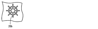
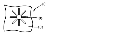
- the gas generation layer 20 may be formed with one or a plurality of grooves 20b connected to the openings 14a. According to this, it is possible to efficiently supply the gas generated in the portion away from the opening 14 a of the gas generation layer 20 to the microchannel 14.
- a plurality of grooves 20b so as to extend radially from a portion corresponding to the opening 14a. This is because gas can be supplied to the microchannel 14 from a wider area of the gas generation layer 20.
- a ring-shaped or horseshoe-shaped groove for communicating a plurality of radially formed grooves 20b may be further formed.
- the number and shape of the grooves 20b are not limited at all.
- the surface of the gas generation layer 20 on the substrate 10 side may be a rough surface. Even in such a case, the gas generated in the portion away from the opening 14a of the gas generation layer 20 can also be efficiently supplied to the microchannel 14.
- a groove 10c may be formed in the surface 10a of the substrate 10 as shown in FIGS. Further, the groove 20 b may be formed in the gas generation layer 20 and the groove 10 c may be formed in the surface 10 a of the substrate 10.
- Example 1 An acrylic copolymer (weight average molecular weight 700,000) of 96.5 parts by weight of 2-ethylhexyl acrylate, 3 parts by weight of acrylic acid, and 0.5 parts by weight of 2-hydroxyethyl acrylate was prepared.
- the adhesive resin binder solution is blended with 2,3,4,4′-tetrahydroxybenzozonone as a photoacid generator and sodium hydrogen carbonate as an acid stimulating gas generator to produce a photoresponsive gas.
- the material was generated.
- the blending amounts of 2,3,4,4'-tetrahydroxybenzozonone and sodium hydrogen carbonate were 35 parts by weight and 75 parts by weight with respect to 100 parts by weight of the acrylic copolymer.
- the photoresponsive gas generating material was cast on a 50 ⁇ m-thick PET film subjected to anchor treatment, and then dried to produce a photoresponsive gas generating film.
- the thickness of the photoresponsive gas generating film after drying was about 30 ⁇ m.
- Example 2 2,2′-azobis- (N-butyl-2-methylpropionamide) was used as the photogas generator in place of the photoacid generator and acid stimulating gas generator in the adhesive resin binder solution of Experimental Example 1.
- a photoresponsive gas generating film was produced in the same manner as in Experimental Example 1 except that 20 parts by weight of) was added to 100 parts by weight of the acrylic copolymer.
- Example 3 A photoresponsive gas generating film was produced in the same manner as in Experimental Example 2, except that 3-azidomethyl-3-methyloxetane was used as the photogas generating agent.
- a polymethylmethacrylate (PMMA) plate having a size of 50 mm ⁇ 50 mm, a thickness of 5 mm, and a through hole having a diameter of 1 mm at the center was prepared.
- Each photoresponsive gas generating film obtained in Experimental Examples 1 to 3 was affixed to a PMMA plate using a hand roller.
- a gas generation quantitative measurement apparatus including a tube through which gas passes and a gas pipette for measuring a gas amount attached to one end of the tube was prepared.
- the other end of the tube of the gas generation quantitative measurement apparatus was connected to the opening on the opposite side of the through-hole formed in the PMMA plate from the photoresponsive gas generation film.
- the gas generation quantitative measurement device measures the water level change due to the gas generated from the form from this initial state, with water flowing from one side of the tube and filling the water to the reference line of the pipette as the initial state. It is.
- the amount of gas generated when the photoresponsive gas generating film was irradiated with ultraviolet light having a wavelength of 365 nm at a light irradiation intensity of 24 mW / cm 2 (365 nm) using a high-pressure mercury lamp was measured. Further, 200 seconds after irradiation with ultraviolet rays, the total amount of the photoacid generator and the acid stimulating gas generator and the amount of gas generated per 1 g of the photogas generator were measured and evaluated according to the following evaluation criteria. .
- Gas generation amount is 0.5 or more and less than 1.0 mL ⁇ : Gas generation amount per 1 g of the photogas generating agent is less than 0.5 mL The results are shown below.
- two openings 14 a are formed for one microchannel 14.
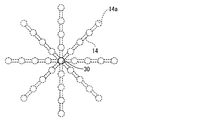
- a gas outlet 30 for discharging gas from the microchannel 14 is formed at the end of the microchannel 14.
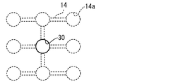
- openings 14 a are formed in series with respect to one microchannel 14.
- the gas outlet 30 is formed in a portion between adjacent openings 14 a of the microchannel 14.
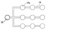
- a plurality of microchannels 14 are connected in parallel to one gas outlet 30. Specifically, three micro flow paths 14 are connected in parallel to one gas outlet 30. A plurality of openings 14 a are formed in each microchannel 14.
- microchannels 14 are connected to one gas outlet 30. At least one of the plurality of microchannels 14 is formed in a branched shape.
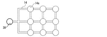
- the plurality of openings 14 a are connected in a mesh shape by the microchannels 14.
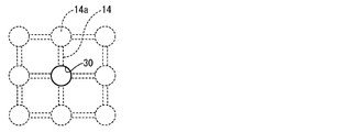
- a gas discharge port 30 is formed at the center of the microchannel 14 formed in a mesh shape.
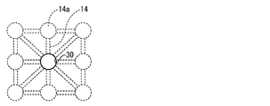
- a plurality of micro flow paths 14 extending radially from the gas outlet 30 are connected to one gas outlet 30.
- one opening 14a is formed in each microchannel.
- each microchannel is connected mutually.
- a plurality of openings 14 a are formed in series at equal intervals in each microchannel 14.
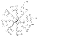
- each microchannel 14 includes a main channel 14 b connected to the gas outlet 30 and a subchannel 14 c.
- the sub channel 14c is connected in parallel to the main channel 14b.
- An opening 14a is also formed in each of the plurality of sub-channels 14c.
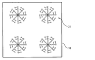
- a plurality of micro flow channel groups 31 including a plurality of micro flow channels 14 connected to one gas discharge port 30 are formed on the substrate 10.
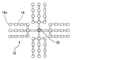
- a plurality of microchannel sets 32 including a plurality of microchannels 14 connected to each other are connected to one gas outlet 30.
- a plurality of microchannel groups 31 including a plurality of microchannel groups 32 are formed on the substrate 10.
- one gas discharge As described above, by forming a plurality of openings 14 a for one micro flow path 14 or connecting a plurality of micro flow paths 14 to one gas discharge port 30, one gas discharge The amount of gas discharged from the outlet 30 can be increased, and the exhaust gas pressure can be increased. In addition, gas can be discharged from one gas discharge port 30 over a long period of time.
- timing of irradiating light to the plurality of openings 14a formed in one or a plurality of microchannels 14 connected to one gas outlet 30 may be equal to or different from each other. Good. By varying the timing of irradiating light to the plurality of openings 14a, the period during which gas can be discharged can be made longer.
Landscapes
- Chemical & Material Sciences (AREA)
- Engineering & Computer Science (AREA)
- Health & Medical Sciences (AREA)
- Chemical Kinetics & Catalysis (AREA)
- General Engineering & Computer Science (AREA)
- Mechanical Engineering (AREA)
- Analytical Chemistry (AREA)
- Dispersion Chemistry (AREA)
- General Health & Medical Sciences (AREA)
- Hematology (AREA)
- Clinical Laboratory Science (AREA)
- Organic Chemistry (AREA)
- Microelectronics & Electronic Packaging (AREA)
- Computer Hardware Design (AREA)
- Micromachines (AREA)
- Jet Pumps And Other Pumps (AREA)
- Automatic Analysis And Handling Materials Therefor (AREA)
- Organic Low-Molecular-Weight Compounds And Preparation Thereof (AREA)
- Feeding, Discharge, Calcimining, Fusing, And Gas-Generation Devices (AREA)
Abstract
Description
(発明の効果)
2 …マイクロポンプシステム
3 …ガス発生部
10 …基板
10a…第1の主面
10b…第2の主面
10c…溝
11 …第1の基板
12 …第2の基板
13 …第3の基板
14 …マイクロ流路
14a…開口
14b…主流路
14c…副流路
20 …ガス発生層
20a…連通孔
20b…溝
21 …バリア層
21a…外周部
22 …遮光層
23 …光
30 …ガス排出口
31 …マイクロ流路群
32 …マイクロ流路組
33,34…粘接着剤層
35…貫通孔
以下、本発明の好ましい形態の一例について、図1に示すマイクロ流体デバイス1を例に挙げて説明する。但し、マイクロ流体デバイス1は、単なる例示であって、本発明は、マイクロ流体デバイス1に限定されるものではない。
光塩基発生剤(A)は、例えば、コバルトアミン系錯体、カルバミン酸o-ニトロベンジル、オキシムエステル、下記の式(4)で表わされる光の照射によりアミンを発生させるカルバモイルオキシイミノ基含有化合物、及び下記の式(5)で表わされるカルボン酸(a1)と塩基性化合物(a2)との塩からなる群から選択された少なくとも1種であってもよい。












上記光塩基発生剤(A)100重量部に対し、20~100重量部の割合でアミノアルキル化合物(C)がさらに含有されていることが好ましい。20重量部未満では、アミノアルキル化合物(C)を添加した効果が十分得られないことがあり、100重量部を越えると光塩基発生剤から生じるラジカルは、光塩基発生剤と等量であり、過剰に加えても未反応で反応が終了することがある。
極性が低い粘接着剤樹脂を用いることにより、基板10の極性が低い場合においても、基板10とガス発生層20との密着強度を高めることができる。

上記第1の実施形態では、マイクロ流体デバイス1にひとつのガス発生部3のみが形成されている例について説明した。但し、本発明において、図2に示すように、ガス発生部3は複数形成されていてもよい。言い換えれば、マイクロ流路14は複数設けられていてもよい。この場合において、ガス発生層20は、複数のガス発生部3に共通してひとつのみ設けてもよい。
上記第2の実施形態では、ガス発生層20は、複数のガス発生部3に共通してひとつのみ設けられている例について説明した。但し、図3に示すように、ガス発生層20を複数のガス発生部3のそれぞれに対して別個に設けてもよい。この場合、ガス発生層20と基板10とが必ずしも貼付されている必要はない。例えば、隣接するガス発生層20の間においてバリア層21と基板10とを接着させ、バリア層21を基板10に対して固定すると共に、バリア層21と基板10との間にガス発生層20を配置してもよい。
図4は、第4の実施形態に係るマイクロ流体デバイスの断面図である。図4に示すように、本実施形態では、バリア層21は、ガス発生層20の外周に位置する外周部21aにおいて、全周にわたって基板10に接合されている。これにより、基板10とバリア層21との間に実質的に気密された空間が形成されている。そして、その気密空間内にガス発生層20が配置されている。
図5は、第5の実施形態に係るマイクロ流体デバイスの断面図である。図5に示すように、ガス発生層20には、開口14aに接続された1又は複数の溝20bが形成されていてもよい。これによれば、ガス発生層20の開口14aから離れた部分において発生したガスも効率的にマイクロ流路14に供給することが可能となる。
2-エチルへキシルアクリレート96.5重量部、アクリル酸3重量部、2-ヒドロキシエチルアクリレート0.5重量部のアクリル系共重合体(重量平均分子量70万)を用意した。
実験例1の粘接着剤樹脂バインダー溶液に、上記光酸発生剤及び酸刺激ガス発生剤に替えて、光ガス発生剤として2,2’-アゾビス-(N-ブチル-2-メチルプロピオンアミド)をアクリル系共重合体100重量部に対して20重量部配合した以外は、実験例1と同様にして、光応答性ガス発生フィルムを作製した。
光ガス発生剤として3-アジドメチル-3-メチルオキセタンを用いたこと以外は実験例2と同様にして、光応答性ガス発生フィルムを作製した。
大きさ50mm×50mm、厚さ5mmで中心に直径1mmの貫通孔が形成されたポリメチルメタクリレート(PMMA)製板を用意した。実験例1~3で得られた各光応答性ガス発生フィルムを、ハンドローラーを用いて、PMMA製板に貼付した。
◎:光ガス発生剤1gあたりのガスの発生量が1.5mL以上
○:光ガス発生剤1gあたりのガスの発生量が1.0mL以上、1.5mL未満
△:光ガス発生剤1gあたりのガスの発生量が0.5以上、1.0mL未満
×:光ガス発生剤1gあたりのガスの発生量が0.5mL未満
結果を以下に示す。
実験例1:○
実験例2:◎
実験例3:◎
上記実施形態では、1つのマイクロ流路14に対して開口14aが1つだけ形成されている例について説明した。ただし、本発明はこの構成に限定されない。例えば、1つのマイクロ流路14に対して複数の開口14aが形成されていてもよい。また、基板10には、相互に接続された複数のマイクロ流路14が形成されていてもよい。図10~図22に、マイクロ流路14の形成例を示す。
Claims (17)
- ガス発生部を有するマイクロ流体デバイスであって、
前記ガス発生部は、
第1の主面と第2の主面とを有し、前記第1の主面に開口するマイクロ流路が形成された基板と、
前記基板の第1の主面に、前記開口を覆うように配置され、外部刺激を受けることによりガスを発生させるガス発生層と、
を有するマイクロ流体デバイス。 - 前記ガス発生層は、前記第1の主面に貼付されているガス発生フィルムである、請求項1に記載のマイクロ流体デバイス。
- 前記ガス発生部は、前記ガス発生層の前記基板側とは反対側の表面に設けられたバリア層をさらに有する、請求項1又は2に記載のマイクロ流体デバイス。
- 前記バリア層は、ガス発生層を覆うように配置されており、前記ガス発生層の外周全体にわたって前記基板に接合されている、請求項3に記載のマイクロ流体デバイス。
- 前記ガス発生層には、一端が前記開口に接続され、他端が前記基板とは反対側の表面に接続された連通孔が形成されている、請求項3又は4に記載のマイクロ流体デバイス。
- 前記バリア層は、ガラス製又は樹脂製の膜又は基板である、請求項3~5のいずれか一項に記載のマイクロ流体デバイス。
- 前記基板には、前記マイクロ流路が複数設けられており、
前記ガス発生層は、光が照射されることによりガスを発生させるガス発生剤を含み、
平面視において、隣接する前記マイクロ流路の開口相互間に設けられ、前記ガス発生層を遮光する遮光層をさらに備える、請求項1~6のいずれか一項に記載のマイクロ流体デバイス。 - 前記ガス発生層は、前記基板に貼付されており、前記ガス発生層の前記基板側の表面及び前記基板の第1の主面のうちの少なくとも一方には、前記開口に接続された溝又は孔が形成されている、請求項1~7のいずれか一項に記載のマイクロ流体デバイス。
- 前記溝又は孔は、前記開口から前記基板の板面方向に延びている、請求項8に記載のマイクロ流体デバイス。
- 前記溝又は孔が複数形成されており、
前記複数の溝又は孔は、前記基板の板面方向において、前記開口から放射状に延びている、請求項8又は9に記載のマイクロ流体デバイス。 - 前記ガス発生層の前記基板側の表面及び前記基板の第1の主面のうちの少なくとも一方は、粗面である、請求項1~10のいずれか一項に記載のマイクロ流体デバイス。
- 前記ガス発生層は、外部刺激を受けることによりガスを発生させるガス発生剤を含む、請求項1~6,8~11のいずれか一項に記載のマイクロ流体デバイス。
- 前記ガス発生剤は、アゾ化合物及びアジド化合物のうちの少なくとも一方を含む、請求項12に記載のマイクロ流体デバイス。
- 前記ガス発生層は、バインダー樹脂をさらに含む、請求項12または13に記載のマイクロ流体デバイス。
- 前記バインダー樹脂は、粘接着剤樹脂を含む、請求項14に記載のマイクロ流体デバイス。
- 前記マイクロ流路には、前記第1の主面に対する開口が複数形成されている、請求項1~15のいずれか一項に記載のマイクロ流体デバイス。
- 前記基板には、前記マイクロ流路が複数形成されており、前記複数のマイクロ流路は、相互に接続されている、請求項1~16のいずれか一項に記載のマイクロ流体デバイス。
Priority Applications (4)
| Application Number | Priority Date | Filing Date | Title |
|---|---|---|---|
| EP09719615.8A EP2256349B1 (en) | 2008-03-11 | 2009-03-11 | Micro fluid device |
| US12/921,247 US8197773B2 (en) | 2008-03-11 | 2009-03-11 | Micro fluid device |
| JP2009511288A JP5066180B2 (ja) | 2008-03-11 | 2009-03-11 | マイクロ流体デバイス |
| CN200980100731.0A CN102741559B (zh) | 2008-03-11 | 2009-03-11 | 微流体设备 |
Applications Claiming Priority (12)
| Application Number | Priority Date | Filing Date | Title |
|---|---|---|---|
| JP2008061290 | 2008-03-11 | ||
| JP2008-061290 | 2008-03-11 | ||
| JP2008-076178 | 2008-03-24 | ||
| JP2008076178 | 2008-03-24 | ||
| JP2008157448 | 2008-06-17 | ||
| JP2008-157448 | 2008-06-17 | ||
| JP2008187492 | 2008-07-18 | ||
| JP2008-187492 | 2008-07-18 | ||
| JP2008-223331 | 2008-09-01 | ||
| JP2008223331 | 2008-09-01 | ||
| JP2008231970 | 2008-09-10 | ||
| JP2008-231970 | 2008-09-10 |
Publications (1)
| Publication Number | Publication Date |
|---|---|
| WO2009113567A1 true WO2009113567A1 (ja) | 2009-09-17 |
Family
ID=41065228
Family Applications (1)
| Application Number | Title | Priority Date | Filing Date |
|---|---|---|---|
| PCT/JP2009/054623 Ceased WO2009113567A1 (ja) | 2008-03-11 | 2009-03-11 | マイクロ流体デバイス |
Country Status (6)
| Country | Link |
|---|---|
| US (1) | US8197773B2 (ja) |
| EP (2) | EP2256349B1 (ja) |
| JP (3) | JP5066180B2 (ja) |
| KR (1) | KR101560424B1 (ja) |
| CN (2) | CN102146905B (ja) |
| WO (1) | WO2009113567A1 (ja) |
Cited By (6)
| Publication number | Priority date | Publication date | Assignee | Title |
|---|---|---|---|---|
| JP2011072876A (ja) * | 2009-09-29 | 2011-04-14 | Sekisui Chem Co Ltd | マイクロ流体デバイス |
| JP2012072007A (ja) * | 2010-09-28 | 2012-04-12 | Sekisui Chem Co Ltd | ガス発生剤及びマイクロポンプ |
| JP2013256626A (ja) * | 2012-06-14 | 2013-12-26 | Sekisui Chem Co Ltd | ガス発生材及びマイクロポンプ |
| JP2014118325A (ja) * | 2012-12-17 | 2014-06-30 | Sekisui Chem Co Ltd | マイクロポンプ用ガス発生材及びマイクロポンプ |
| JP2018057366A (ja) * | 2016-09-30 | 2018-04-12 | 積水化学工業株式会社 | マイクロ流体デバイス及び流体の送液方法 |
| WO2023286681A1 (ja) * | 2021-07-12 | 2023-01-19 | 積水化学工業株式会社 | テープ積層体、マイクロ流路チップ、及びマイクロ流体デバイス |
Families Citing this family (13)
| Publication number | Priority date | Publication date | Assignee | Title |
|---|---|---|---|---|
| US8197773B2 (en) * | 2008-03-11 | 2012-06-12 | Sekisui Chemical Co., Ltd. | Micro fluid device |
| JP5588281B2 (ja) * | 2010-09-18 | 2014-09-10 | 積水化学工業株式会社 | ガス発生剤及びマイクロポンプ |
| JP5555648B2 (ja) * | 2011-03-03 | 2014-07-23 | 積水化学工業株式会社 | マイクロポンプ |
| JP5699007B2 (ja) * | 2011-03-09 | 2015-04-08 | 積水化学工業株式会社 | ガス発生材及びマイクロポンプ |
| CN103717553B (zh) * | 2012-06-08 | 2015-08-19 | 积水化学工业株式会社 | 气体发生材料及微型泵 |
| JP5957306B2 (ja) * | 2012-06-14 | 2016-07-27 | 積水化学工業株式会社 | ガス発生材及びマイクロポンプ |
| US10731062B2 (en) | 2012-10-15 | 2020-08-04 | Sekisui Chemical Co., Ltd. | Gas-generating material and micropump |
| JP6098726B2 (ja) | 2013-08-30 | 2017-03-22 | Jsr株式会社 | 被接着物回収方法、被接着物回収装置、ガス発生膜および樹脂組成物 |
| EP2923754B1 (en) * | 2014-03-26 | 2019-08-14 | Corning Incorporated | Modular photochemical flow reactor system |
| CN103934049B (zh) * | 2014-04-14 | 2016-06-08 | 西安交通大学 | 一种刻度式定量即时诊断微流控芯片及其制备方法 |
| US9604209B2 (en) | 2015-03-19 | 2017-03-28 | International Business Machines Corporation | Microfluidic device with anti-wetting, venting areas |
| KR102276639B1 (ko) * | 2019-08-06 | 2021-07-12 | 연세대학교 산학협력단 | 미세유체 디바이스 및 이를 포함하는 플레이트 |
| EP4220185A4 (en) * | 2020-09-28 | 2024-10-23 | Sekisui Chemical Co., Ltd. | Inspection chip |
Citations (5)
| Publication number | Priority date | Publication date | Assignee | Title |
|---|---|---|---|---|
| JP2002138076A (ja) | 2000-08-21 | 2002-05-14 | Sekisui Chem Co Ltd | 光照射によりアミンを発生する化合物及び光硬化性組成物 |
| JP2005032537A (ja) * | 2003-07-11 | 2005-02-03 | Toray Ind Inc | 直下型バックライト |
| JP2005297102A (ja) | 2004-04-08 | 2005-10-27 | Sekisui Chem Co Ltd | マイクロ全分析システム |
| JP2005300425A (ja) * | 2004-04-14 | 2005-10-27 | Sekisui Chem Co Ltd | マイクロ全分析システム |
| JP2007279069A (ja) * | 2006-03-09 | 2007-10-25 | Sekisui Chem Co Ltd | マイクロ流体デバイスおよび微量液体希釈方法 |
Family Cites Families (8)
| Publication number | Priority date | Publication date | Assignee | Title |
|---|---|---|---|---|
| EP1463796B1 (en) * | 2001-11-30 | 2013-01-09 | Fluidigm Corporation | Microfluidic device and methods of using same |
| KR20040105546A (ko) * | 2002-01-15 | 2004-12-16 | 세키스이가가쿠 고교가부시키가이샤 | Ic칩의 제조 방법 |
| JP4516346B2 (ja) * | 2004-04-14 | 2010-08-04 | 積水化学工業株式会社 | マイクロ全分析システム |
| JP3952036B2 (ja) * | 2004-05-13 | 2007-08-01 | コニカミノルタセンシング株式会社 | マイクロ流体デバイス並びに試液の試験方法および試験システム |
| US8905073B2 (en) * | 2006-03-09 | 2014-12-09 | Sekisui Chemical Co. Ltd. | Micro fluid device and trace liquid diluting method |
| US8197773B2 (en) * | 2008-03-11 | 2012-06-12 | Sekisui Chemical Co., Ltd. | Micro fluid device |
| TWI348900B (en) * | 2008-06-18 | 2011-09-21 | Ind Tech Res Inst | Fluidic device |
| US8075855B2 (en) * | 2008-06-20 | 2011-12-13 | Silverbrook Research Pty Ltd | MEMS integrated circuit comprising peristaltic microfluidic pump |
-
2009
- 2009-03-11 US US12/921,247 patent/US8197773B2/en active Active
- 2009-03-11 KR KR1020107006298A patent/KR101560424B1/ko not_active Expired - Fee Related
- 2009-03-11 CN CN201110036693.6A patent/CN102146905B/zh not_active Expired - Fee Related
- 2009-03-11 EP EP09719615.8A patent/EP2256349B1/en active Active
- 2009-03-11 EP EP16174390.1A patent/EP3093502B1/en active Active
- 2009-03-11 WO PCT/JP2009/054623 patent/WO2009113567A1/ja not_active Ceased
- 2009-03-11 CN CN200980100731.0A patent/CN102741559B/zh not_active Expired - Fee Related
- 2009-03-11 JP JP2009511288A patent/JP5066180B2/ja active Active
- 2009-11-17 JP JP2009262014A patent/JP4528353B2/ja not_active Expired - Fee Related
- 2009-11-17 JP JP2009262013A patent/JP4528352B2/ja not_active Expired - Fee Related
Patent Citations (5)
| Publication number | Priority date | Publication date | Assignee | Title |
|---|---|---|---|---|
| JP2002138076A (ja) | 2000-08-21 | 2002-05-14 | Sekisui Chem Co Ltd | 光照射によりアミンを発生する化合物及び光硬化性組成物 |
| JP2005032537A (ja) * | 2003-07-11 | 2005-02-03 | Toray Ind Inc | 直下型バックライト |
| JP2005297102A (ja) | 2004-04-08 | 2005-10-27 | Sekisui Chem Co Ltd | マイクロ全分析システム |
| JP2005300425A (ja) * | 2004-04-14 | 2005-10-27 | Sekisui Chem Co Ltd | マイクロ全分析システム |
| JP2007279069A (ja) * | 2006-03-09 | 2007-10-25 | Sekisui Chem Co Ltd | マイクロ流体デバイスおよび微量液体希釈方法 |
Cited By (8)
| Publication number | Priority date | Publication date | Assignee | Title |
|---|---|---|---|---|
| JP2011072876A (ja) * | 2009-09-29 | 2011-04-14 | Sekisui Chem Co Ltd | マイクロ流体デバイス |
| JP2012072007A (ja) * | 2010-09-28 | 2012-04-12 | Sekisui Chem Co Ltd | ガス発生剤及びマイクロポンプ |
| JP2013256626A (ja) * | 2012-06-14 | 2013-12-26 | Sekisui Chem Co Ltd | ガス発生材及びマイクロポンプ |
| JP2014118325A (ja) * | 2012-12-17 | 2014-06-30 | Sekisui Chem Co Ltd | マイクロポンプ用ガス発生材及びマイクロポンプ |
| JP2018057366A (ja) * | 2016-09-30 | 2018-04-12 | 積水化学工業株式会社 | マイクロ流体デバイス及び流体の送液方法 |
| WO2023286681A1 (ja) * | 2021-07-12 | 2023-01-19 | 積水化学工業株式会社 | テープ積層体、マイクロ流路チップ、及びマイクロ流体デバイス |
| JPWO2023286681A1 (ja) * | 2021-07-12 | 2023-01-19 | ||
| JP7750960B2 (ja) | 2021-07-12 | 2025-10-07 | 積水化学工業株式会社 | テープ積層体、マイクロ流路チップ、及びマイクロ流体デバイス |
Also Published As
| Publication number | Publication date |
|---|---|
| EP3093502B1 (en) | 2018-07-04 |
| JPWO2009113567A1 (ja) | 2011-07-21 |
| US20110044863A1 (en) | 2011-02-24 |
| JP2010107515A (ja) | 2010-05-13 |
| EP3093502A1 (en) | 2016-11-16 |
| US8197773B2 (en) | 2012-06-12 |
| CN102741559B (zh) | 2014-12-10 |
| KR20100137410A (ko) | 2010-12-30 |
| EP2256349A1 (en) | 2010-12-01 |
| KR101560424B1 (ko) | 2015-10-14 |
| JP2010105159A (ja) | 2010-05-13 |
| EP2256349A4 (en) | 2015-04-22 |
| CN102741559A (zh) | 2012-10-17 |
| JP5066180B2 (ja) | 2012-11-07 |
| CN102146905B (zh) | 2014-03-26 |
| JP4528352B2 (ja) | 2010-08-18 |
| CN102146905A (zh) | 2011-08-10 |
| JP4528353B2 (ja) | 2010-08-18 |
| EP2256349B1 (en) | 2017-04-26 |
Similar Documents
| Publication | Publication Date | Title |
|---|---|---|
| JP5066180B2 (ja) | マイクロ流体デバイス | |
| CN101978173B (zh) | 光响应性气体发生材料、微泵及微流体设备 | |
| JP2012072007A (ja) | ガス発生剤及びマイクロポンプ | |
| EP2860167B1 (en) | Gas generating material, and micropump | |
| JP5291415B2 (ja) | マイクロ流体送液装置 | |
| US10731062B2 (en) | Gas-generating material and micropump | |
| JP2011072876A (ja) | マイクロ流体デバイス | |
| WO2023286681A1 (ja) | テープ積層体、マイクロ流路チップ、及びマイクロ流体デバイス | |
| JP7144140B2 (ja) | ガス発生材、ガス発生材の製造方法及びマイクロポンプ | |
| JP2012188306A (ja) | ガス発生材及びマイクロポンプ | |
| JP5639137B2 (ja) | ガス発生材及びマイクロポンプ | |
| JP6110652B2 (ja) | マイクロポンプ用ガス発生材及びマイクロポンプ | |
| JP2022179049A (ja) | マイクロ流路チップ、マイクロ流体デバイス、送液システム、及び送液方法 | |
| JP2013071847A (ja) | ガス発生材及びマイクロポンプ | |
| JP2014214598A (ja) | マイクロポンプ装置 | |
| JP2015054798A (ja) | マイクロポンプにおけるガスの発生方法 |
Legal Events
| Date | Code | Title | Description |
|---|---|---|---|
| ENP | Entry into the national phase |
Ref document number: 2009511288 Country of ref document: JP Kind code of ref document: A |
|
| WWE | Wipo information: entry into national phase |
Ref document number: 200980100731.0 Country of ref document: CN |
|
| 121 | Ep: the epo has been informed by wipo that ep was designated in this application |
Ref document number: 09719615 Country of ref document: EP Kind code of ref document: A1 |
|
| ENP | Entry into the national phase |
Ref document number: 20107006298 Country of ref document: KR Kind code of ref document: A |
|
| REEP | Request for entry into the european phase |
Ref document number: 2009719615 Country of ref document: EP |
|
| WWE | Wipo information: entry into national phase |
Ref document number: 2009719615 Country of ref document: EP |
|
| WWE | Wipo information: entry into national phase |
Ref document number: 12921247 Country of ref document: US |
|
| NENP | Non-entry into the national phase |
Ref country code: DE |