WO2009116314A1 - Carte de circuit imprimé pour la récupération de fluide biologique, procédé de fabrication et d'utilisation de cette carte, et biocapteur - Google Patents
Carte de circuit imprimé pour la récupération de fluide biologique, procédé de fabrication et d'utilisation de cette carte, et biocapteur Download PDFInfo
- Publication number
- WO2009116314A1 WO2009116314A1 PCT/JP2009/050830 JP2009050830W WO2009116314A1 WO 2009116314 A1 WO2009116314 A1 WO 2009116314A1 JP 2009050830 W JP2009050830 W JP 2009050830W WO 2009116314 A1 WO2009116314 A1 WO 2009116314A1
- Authority
- WO
- WIPO (PCT)
- Prior art keywords
- circuit board
- body fluid
- measurement units
- support portion
- electrode
- Prior art date
- Legal status (The legal status is an assumption and is not a legal conclusion. Google has not performed a legal analysis and makes no representation as to the accuracy of the status listed.)
- Ceased
Links
Images




Classifications
-
- A—HUMAN NECESSITIES
- A61—MEDICAL OR VETERINARY SCIENCE; HYGIENE
- A61B—DIAGNOSIS; SURGERY; IDENTIFICATION
- A61B5/00—Measuring for diagnostic purposes; Identification of persons
- A61B5/15—Devices for taking samples of blood
- A61B5/157—Devices characterised by integrated means for measuring characteristics of blood
-
- A—HUMAN NECESSITIES
- A61—MEDICAL OR VETERINARY SCIENCE; HYGIENE
- A61B—DIAGNOSIS; SURGERY; IDENTIFICATION
- A61B5/00—Measuring for diagnostic purposes; Identification of persons
- A61B5/145—Measuring characteristics of blood in vivo, e.g. gas concentration or pH-value ; Measuring characteristics of body fluids or tissues, e.g. interstitial fluid or cerebral tissue
- A61B5/14532—Measuring characteristics of blood in vivo, e.g. gas concentration or pH-value ; Measuring characteristics of body fluids or tissues, e.g. interstitial fluid or cerebral tissue for measuring glucose, e.g. by tissue impedance measurement
-
- A—HUMAN NECESSITIES
- A61—MEDICAL OR VETERINARY SCIENCE; HYGIENE
- A61B—DIAGNOSIS; SURGERY; IDENTIFICATION
- A61B5/00—Measuring for diagnostic purposes; Identification of persons
- A61B5/145—Measuring characteristics of blood in vivo, e.g. gas concentration or pH-value ; Measuring characteristics of body fluids or tissues, e.g. interstitial fluid or cerebral tissue
- A61B5/1468—Measuring characteristics of blood in vivo, e.g. gas concentration or pH-value ; Measuring characteristics of body fluids or tissues, e.g. interstitial fluid or cerebral tissue using chemical or electrochemical methods, e.g. by polarographic means
- A61B5/1486—Measuring characteristics of blood in vivo, e.g. gas concentration or pH-value ; Measuring characteristics of body fluids or tissues, e.g. interstitial fluid or cerebral tissue using chemical or electrochemical methods, e.g. by polarographic means using enzyme electrodes, e.g. with immobilised oxidase
-
- A—HUMAN NECESSITIES
- A61—MEDICAL OR VETERINARY SCIENCE; HYGIENE
- A61B—DIAGNOSIS; SURGERY; IDENTIFICATION
- A61B5/00—Measuring for diagnostic purposes; Identification of persons
- A61B5/15—Devices for taking samples of blood
- A61B5/150007—Details
- A61B5/150015—Source of blood
- A61B5/150022—Source of blood for capillary blood or interstitial fluid
-
- A—HUMAN NECESSITIES
- A61—MEDICAL OR VETERINARY SCIENCE; HYGIENE
- A61B—DIAGNOSIS; SURGERY; IDENTIFICATION
- A61B5/00—Measuring for diagnostic purposes; Identification of persons
- A61B5/15—Devices for taking samples of blood
- A61B5/150007—Details
- A61B5/150206—Construction or design features not otherwise provided for; manufacturing or production; packages; sterilisation of piercing element, piercing device or sampling device
- A61B5/150274—Manufacture or production processes or steps for blood sampling devices
- A61B5/150282—Manufacture or production processes or steps for blood sampling devices for piercing elements, e.g. blade, lancet, canula, needle
-
- A—HUMAN NECESSITIES
- A61—MEDICAL OR VETERINARY SCIENCE; HYGIENE
- A61B—DIAGNOSIS; SURGERY; IDENTIFICATION
- A61B5/00—Measuring for diagnostic purposes; Identification of persons
- A61B5/15—Devices for taking samples of blood
- A61B5/150007—Details
- A61B5/150358—Strips for collecting blood, e.g. absorbent
-
- A—HUMAN NECESSITIES
- A61—MEDICAL OR VETERINARY SCIENCE; HYGIENE
- A61B—DIAGNOSIS; SURGERY; IDENTIFICATION
- A61B5/00—Measuring for diagnostic purposes; Identification of persons
- A61B5/15—Devices for taking samples of blood
- A61B5/150007—Details
- A61B5/150374—Details of piercing elements or protective means for preventing accidental injuries by such piercing elements
- A61B5/150381—Design of piercing elements
- A61B5/150412—Pointed piercing elements, e.g. needles, lancets for piercing the skin
- A61B5/150435—Specific design of proximal end
-
- A—HUMAN NECESSITIES
- A61—MEDICAL OR VETERINARY SCIENCE; HYGIENE
- A61B—DIAGNOSIS; SURGERY; IDENTIFICATION
- A61B5/00—Measuring for diagnostic purposes; Identification of persons
- A61B5/15—Devices for taking samples of blood
- A61B5/150007—Details
- A61B5/150374—Details of piercing elements or protective means for preventing accidental injuries by such piercing elements
- A61B5/150381—Design of piercing elements
- A61B5/150503—Single-ended needles
-
- A—HUMAN NECESSITIES
- A61—MEDICAL OR VETERINARY SCIENCE; HYGIENE
- A61B—DIAGNOSIS; SURGERY; IDENTIFICATION
- A61B5/00—Measuring for diagnostic purposes; Identification of persons
- A61B5/15—Devices for taking samples of blood
- A61B5/150007—Details
- A61B5/150374—Details of piercing elements or protective means for preventing accidental injuries by such piercing elements
- A61B5/150381—Design of piercing elements
- A61B5/150526—Curved or bent needles
-
- A—HUMAN NECESSITIES
- A61—MEDICAL OR VETERINARY SCIENCE; HYGIENE
- A61B—DIAGNOSIS; SURGERY; IDENTIFICATION
- A61B5/00—Measuring for diagnostic purposes; Identification of persons
- A61B5/15—Devices for taking samples of blood
- A61B5/151—Devices specially adapted for taking samples of capillary blood, e.g. by lancets, needles or blades
- A61B5/15101—Details
- A61B5/15103—Piercing procedure
- A61B5/15105—Purely manual piercing, i.e. the user pierces the skin without the assistance of any driving means or driving devices
-
- A—HUMAN NECESSITIES
- A61—MEDICAL OR VETERINARY SCIENCE; HYGIENE
- A61B—DIAGNOSIS; SURGERY; IDENTIFICATION
- A61B5/00—Measuring for diagnostic purposes; Identification of persons
- A61B5/15—Devices for taking samples of blood
- A61B5/151—Devices specially adapted for taking samples of capillary blood, e.g. by lancets, needles or blades
- A61B5/15101—Details
- A61B5/15126—Means for controlling the lancing movement, e.g. 2D- or 3D-shaped elements, tooth-shaped elements or sliding guides
- A61B5/15128—Means for controlling the lancing movement, e.g. 2D- or 3D-shaped elements, tooth-shaped elements or sliding guides comprising 2D- or 3D-shaped elements, e.g. cams, curved guide rails or threads
-
- A—HUMAN NECESSITIES
- A61—MEDICAL OR VETERINARY SCIENCE; HYGIENE
- A61B—DIAGNOSIS; SURGERY; IDENTIFICATION
- A61B5/00—Measuring for diagnostic purposes; Identification of persons
- A61B5/15—Devices for taking samples of blood
- A61B5/151—Devices specially adapted for taking samples of capillary blood, e.g. by lancets, needles or blades
- A61B5/15101—Details
- A61B5/15126—Means for controlling the lancing movement, e.g. 2D- or 3D-shaped elements, tooth-shaped elements or sliding guides
- A61B5/1513—Means for controlling the lancing movement, e.g. 2D- or 3D-shaped elements, tooth-shaped elements or sliding guides comprising linear sliding guides
-
- A—HUMAN NECESSITIES
- A61—MEDICAL OR VETERINARY SCIENCE; HYGIENE
- A61B—DIAGNOSIS; SURGERY; IDENTIFICATION
- A61B5/00—Measuring for diagnostic purposes; Identification of persons
- A61B5/15—Devices for taking samples of blood
- A61B5/151—Devices specially adapted for taking samples of capillary blood, e.g. by lancets, needles or blades
- A61B5/15146—Devices loaded with multiple lancets simultaneously, e.g. for serial firing without reloading, for example by use of stocking means.
-
- A—HUMAN NECESSITIES
- A61—MEDICAL OR VETERINARY SCIENCE; HYGIENE
- A61B—DIAGNOSIS; SURGERY; IDENTIFICATION
- A61B5/00—Measuring for diagnostic purposes; Identification of persons
- A61B5/15—Devices for taking samples of blood
- A61B5/151—Devices specially adapted for taking samples of capillary blood, e.g. by lancets, needles or blades
- A61B5/15146—Devices loaded with multiple lancets simultaneously, e.g. for serial firing without reloading, for example by use of stocking means.
- A61B5/15148—Constructional features of stocking means, e.g. strip, roll, disc, cartridge, belt or tube
- A61B5/15149—Arrangement of piercing elements relative to each other
- A61B5/15153—Multiple piercing elements stocked in a single compartment
-
- A—HUMAN NECESSITIES
- A61—MEDICAL OR VETERINARY SCIENCE; HYGIENE
- A61B—DIAGNOSIS; SURGERY; IDENTIFICATION
- A61B5/00—Measuring for diagnostic purposes; Identification of persons
- A61B5/15—Devices for taking samples of blood
- A61B5/151—Devices specially adapted for taking samples of capillary blood, e.g. by lancets, needles or blades
- A61B5/15146—Devices loaded with multiple lancets simultaneously, e.g. for serial firing without reloading, for example by use of stocking means.
- A61B5/15148—Constructional features of stocking means, e.g. strip, roll, disc, cartridge, belt or tube
- A61B5/15157—Geometry of stocking means or arrangement of piercing elements therein
- A61B5/15159—Piercing elements stocked in or on a disc
- A61B5/15161—Characterized by propelling the piercing element in a radial direction relative to the disc
-
- A—HUMAN NECESSITIES
- A61—MEDICAL OR VETERINARY SCIENCE; HYGIENE
- A61B—DIAGNOSIS; SURGERY; IDENTIFICATION
- A61B2562/00—Details of sensors; Constructional details of sensor housings or probes; Accessories for sensors
- A61B2562/02—Details of sensors specially adapted for in-vivo measurements
- A61B2562/0295—Strip shaped analyte sensors for apparatus classified in A61B5/145 or A61B5/157
Definitions
- the present invention relates to a circuit board for collecting body fluid, a method for manufacturing a circuit board for collecting body fluid, a method for using the circuit board for collecting body fluid, and a biosensor including the circuit board for collecting body fluid.
- Diabetes is insulin-dependent (type I) and non-insulin-dependent (type II), and the former requires regular administration of insulin. Therefore, in the former, a treatment method is adopted in which a patient collects blood himself, measures blood glucose level himself, and administers insulin by himself at a dose corresponding to the blood glucose level.
- blood glucose level measuring devices are known in which the patient himself can collect blood individually and measure the blood glucose level.
- a fluid collection device includes a reaction zone in which an electrode is inserted and provided in the center of the main body, a puncture needle that protrudes outward from the center of the main body, and a capillary passage that communicates the electrode and the puncture needle (for example, see the following Patent Document 1.) JP 2004-493 A
- the preparation for measurement is simple because the puncture needle and the reaction zone are formed integrally with the main body.
- an electrode that is a separate member from the reaction zone is inserted into the reaction zone to measure blood components. For this reason, the blood detection accuracy becomes unstable, and there is a problem in that it cannot be measured accurately.
- Type I diabetes depending on the symptoms, the patient needs to measure the blood glucose level several times a day, specifically before or after each meal.
- An object of the present invention is to provide a bodily fluid collecting circuit that can accurately measure a component of bodily fluid with a simple configuration and that can be easily measured multiple times on a single bodily fluid collecting circuit board.
- the present invention provides a substrate, a method for manufacturing the same, a method for using the same, and a biosensor including the circuit board for collecting body fluid.
- a circuit board for collecting body fluid of the present invention comprises a puncture needle and a plurality of electrodes arranged in parallel in a fixed direction, each having an electrode for contacting the body fluid collected by puncture of the puncture needle.
- the plurality of measurement units can be arranged radially by winding the support portion. It is characterized by.
- This body fluid sampling circuit board includes a measurement unit including a puncture needle and an electrode. Therefore, body fluid can be flowed out by puncturing with the puncture needle, and the drained body fluid can be easily brought into contact with the electrode of the measurement unit. As a result, according to this circuit board for body fluid collection, components of body fluid can be easily measured with a simple configuration. In addition, in this circuit board for collecting body fluid, a component of body fluid can be measured a plurality of times by a plurality of measurement units provided on one circuit board for collecting body fluid.
- this circuit board for collecting body fluid if a plurality of measurement units are arranged radially by winding the support portion, the circuit board for collecting body fluid rotates in the circumferential direction after using one measurement unit. By doing so, it is possible to exchange the used measurement unit and the unused measurement unit adjacent to the measurement unit upstream in the rotation direction. Therefore, the measurement unit can be easily exchanged for every measurement.
- each measurement unit extends outward with respect to the support portion when the plurality of measurement units are arranged radially. According to the circuit board for body fluid collection, reliable puncture and measurement can be achieved by the plurality of measurement units outside the wound support portion.
- each measurement unit extends inward with respect to the support portion when the plurality of measurement units are arranged radially. According to the circuit board for body fluid collection, reliable puncture and measurement can be achieved by the plurality of measurement units inside the wound support portion.
- the circuit board for collecting body fluid of the present invention further includes a reinforcing portion that is disposed at a distance from the support portion and connects the measurement units adjacent to each other between the measurement units. Is preferred. According to this circuit board for collecting body fluid, even if a plurality of measurement units are arranged radially, the measurement units are connected by the reinforcing portion, so that the plurality of measurement units can be reliably supported. Therefore, reliable puncture and measurement of the measurement unit can be achieved.
- the one end part and the other end part in the parallel direction of the support part further include fitting parts for holding the winding of the support part. It is. According to the circuit board for collecting body fluid, when the support part is wound, the fitting part of the one end part in the parallel direction of the support part and the fitting part of the other end part are fitted to each other. The winding can be held. Therefore, a plurality of measurement units can be surely arranged radially.
- the circuit board for body fluid collection includes a puncture needle and a plurality of measurement units arranged in parallel in a fixed direction, and a plurality of measurement units that are arranged in parallel in a fixed direction, and a body fluid collected by puncture of the puncture needle
- a plurality of measurement units extending radially, and supporting a plurality of the measurement units, wherein the boundaries between the plurality of measurement units and the support portions are bent and the support portions are wound so that the plurality of measurement units are radially provided. It is characterized by being arranged in.
- This body fluid sampling circuit board includes a measurement unit including a puncture needle and an electrode. Therefore, body fluid can be flowed out by puncturing with the puncture needle, and the drained body fluid can be easily brought into contact with the electrode of the measurement unit. As a result, according to this circuit board for body fluid collection, components of body fluid can be easily measured with a simple configuration. In addition, in this circuit board for collecting body fluid, a component of body fluid can be measured a plurality of times by a plurality of measurement units provided on one circuit board for collecting body fluid.
- this bodily fluid collection circuit board a plurality of measurement units are arranged radially by winding the support portion. Therefore, after using one measurement unit, the bodily fluid collection circuit board is circulated. By rotating in the direction, the used measurement unit and an unused measurement unit adjacent to the measurement unit upstream in the rotation direction can be exchanged. Therefore, the measurement unit can be easily exchanged for every measurement.
- each of the measurement units extends outward with respect to the support portion. According to the circuit board for body fluid collection, reliable puncture and measurement can be achieved by the plurality of measurement units outside the wound support portion. In the body fluid sampling circuit board of the present invention, it is preferable that each measurement unit extends inward with respect to the support portion.
- the biosensor of the present invention is characterized by comprising the above-described circuit board for collecting body fluid and a measuring unit that is electrically connected to the electrode and measures a component of the body fluid. According to this biosensor, the bodily fluid discharged from the bodily fluid collecting circuit board is brought into contact with the electrode, and the component of the bodily fluid can be easily measured by the measurement unit electrically connected to the electrode. it can.
- the method for manufacturing a circuit board for collecting body fluid of the present invention includes a step of preparing a metal substrate, a step of forming an insulating layer on the metal substrate, and an electrode for contacting the body fluid on the insulating layer. And a puncture needle for collecting body fluid by puncturing by processing the outer shape of the metal substrate, and extending along the parallel direction, the puncture needle and the electrode provided in parallel in a certain direction
- the metal substrate is contoured so that a plurality of the measurement units can be arranged radially by winding a support portion.
- a plurality of measurement units can be arranged radially by winding the support portion. Therefore, if the circuit board for collecting bodily fluids is arranged in that way, after using one measuring unit, the circuit board for collecting bodily fluids is rotated in the circumferential direction, so that the measuring unit after use and the measuring unit are used. Thus, an unused measuring unit adjacent to the upstream side in the rotation direction can be exchanged. Therefore, the measurement unit can be easily exchanged for every measurement.
- the method for using the circuit board for collecting body fluid uses the circuit board for collecting body fluid produced by the method for producing the circuit board for collecting body fluid described above, and a boundary between the plurality of measurement units and the support portions. And a step of radially arranging a plurality of the measurement units by winding the support portion.
- the plurality of measurement units can be arranged radially by bending the boundaries between the plurality of measurement units and the support and winding the bent support. . Therefore, a plurality of measurement units can be arranged radially by a simple process.
- a plurality of components of body fluid can be obtained by a plurality of measurement units provided on a single body fluid collection circuit board while simply measuring the body fluid components with a simple configuration. Can be measured once. Furthermore, the measurement unit can be easily exchanged for each measurement. Moreover, according to the biosensor of the present invention, the components of body fluid can be easily measured.
- the yield of the circuit board for collecting body fluids can be improved while the measurement unit can be easily replaced for each of a plurality of measurements. Reduction can be achieved. Further, according to the method of using the circuit board for collecting body fluid, a plurality of measurement units can be arranged radially by a simple process.
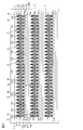
- FIG. 1 is a plan view of a circuit board for blood collection which is an embodiment of the circuit board for body fluid collection of the present invention.
- FIG. 2 is an enlarged plan view of the measurement unit of the circuit board for blood collection shown in FIG.
- FIG. 3 is an enlarged rear view of the measurement unit of the circuit board for blood collection shown in FIG.
- FIG. 4 is a sectional view taken along the line AA in FIG.
- FIG. 5 is a manufacturing process diagram for explaining an embodiment of a method for manufacturing a sampling circuit board according to the present invention, wherein (a) shows a step of preparing a metal substrate, and (b) shows a base insulating layer.
- FIG. 6 is a manufacturing process diagram for explaining the manufacturing method of the circuit board for collection following FIG. 5, and (e) shows a plurality of measurement units each provided with a puncture needle by externally processing a metal substrate.
- the step of forming the support portion, (f) shows the step of applying the drug to the electrode.
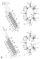
- FIG. 7 is a schematic perspective view for explaining one embodiment of a method for using the circuit board for collecting body fluid of the present invention, wherein (a) is a step of preparing a blood collection circuit board, and (b) is a first step.
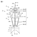
- FIG. 8 is a schematic perspective view of a blood glucose level measuring apparatus as an embodiment of the biosensor of the present invention, on which the blood collection circuit board shown in FIG. 7 is mounted, and (a) shows the drive shaft on the rear side.
- FIG. 9 is a side sectional view for explaining a method of using the blood sugar level measuring apparatus shown in FIG.
- A is a step of preparing a blood glucose level measuring device in which the drive shaft is arranged on the rear side
- (b) is a step of sliding the drive shaft to the front side and puncturing a finger with a puncture needle
- (c) is (D) shows a step of bringing the electrode into close contact with the puncture site by sliding the drive shaft to the rear side and pulling out the puncture needle.
- FIG. 10 is a schematic perspective view for explaining another embodiment of the method of using the circuit board for collecting bodily fluids of the present invention (a form in which each measurement unit extends radially inward with respect to the support portion) (in a plurality of measurement units).
- FIG. 11 is a schematic perspective view for explaining another embodiment of the method for using the circuit board for collecting bodily fluids of the present invention (a form in which each measurement unit extends radially inward with respect to the support portion) (in a plurality of measurement units).
- FIG. 12 is an enlarged plan view of a measurement unit (an embodiment in which the connector portion is substantially W-shaped in plan view) of the circuit board for blood collection which is another embodiment of the circuit board for body fluid collection of the present invention.
- FIG. 13 shows an enlarged plan view of a blood collection circuit board measurement unit (an embodiment in which the connector portion is linear in plan view), which is another embodiment of the body fluid collection circuit board of the present invention.
- FIG. 1 is a plan view of a blood collection circuit board which is an embodiment of a circuit board for body fluid collection of the present invention
- FIG. 2 is an enlarged plan view of a measurement unit of the circuit board for blood collection shown in FIG.
- FIG. 4 is an enlarged rear view of the blood collection circuit board measurement unit shown in FIG. 1,
- FIG. 4 is a cross-sectional view taken along line AA of FIG. 2, and
- FIGS. The manufacturing process figure for demonstrating one Embodiment is shown.
- this blood collection circuit board 1 collects blood by puncturing a skin such as a finger by a patient and measures the amount of glucose in the collected blood as a blood glucose level measuring device 19 (described later) as a biosensor.
- the circuit board 1 for blood collection is prepared as a type that can be measured a plurality of times and can be used repeatedly (continuous use).
- a plurality of blood collection circuit boards 1 are arranged in parallel in a longitudinal sheet-like frame portion 36 extending in the longitudinal direction (the vertical direction in FIG. 1 and corresponding to a puncture direction described later) along the longitudinal direction.
- the circuit boards 1 for blood collection are aligned and arranged at intervals in the longitudinal direction.
- Each blood collection circuit board 1 is supported by the frame portion 36 via the joint portion 37 and is formed to extend in a direction orthogonal to the longitudinal direction (hereinafter referred to as the width direction).
- the joint portion 37 is installed between the both ends in the width direction of the frame portion 36 and the both ends in the width direction of the blood collection circuit board 1 so as to be separable from each other.
- the circuit board for blood collection 1 is integrally provided with a support portion 5 extending along the width direction and a plurality (32) of measurement units 2 supported by the support portion 5 and extending along the longitudinal direction.
- the support portion 5 is formed in a substantially band shape in plan view extending in the width direction, and is formed with a gear 18 and a slit portion 16 as a fitting portion.
- the gear 18 is formed so as to be able to be fitted to a gear board 24 (FIG. 9), which will be described later, over almost the entire surface (excluding both ends in the width direction) of the other end surface in the longitudinal direction (end surface in the puncture direction) of the support portion 5. .
- the gear 18 is formed in a sawtooth shape in which crests and troughs are alternately arranged.
- the slit portions 16 are provided at both ends in the width direction of the support portion 5.
- the slit portion 16 is located at one end in the width direction of the support portion 5 (left end portion in FIG. 1) from the other end surface in the longitudinal direction of the support portion 5 to one side in the longitudinal direction and halfway in the longitudinal direction.
- the slit portion 16 is cut halfway in the longitudinal direction from one end surface in the longitudinal direction of the support portion 5 to the other side in the longitudinal direction at the other end portion in the width direction (right end portion in FIG. 1) of the support portion 5. It is formed in a slit shape. Thereby, the slit part 16 of the both ends of the width direction is mutually fitted when winding the support part 5 mentioned later.
- the measurement unit 2 is disposed so as to protrude from the support portion 5 toward one side in the longitudinal direction (downstream in the puncture direction and upper side in FIGS. 2 and 3). ing. Further, the measurement unit 2 is integrally provided with an upstream side portion 3 disposed on the upstream side in the puncturing direction and a downstream side portion 4 disposed on the downstream side of the upstream side portion 3 in the puncturing direction. As shown in FIG. 1, the upstream side portion 3 is arranged adjacent to the downstream end portion in the puncture direction of the support portion 5 in the puncture direction and is adjacent to the upstream side portion 3 of the measurement unit 2 adjacent in the width direction. Are arranged so as to face each other with a gap therebetween.
- the upstream side portion 3 is provided with a terminal 9 (described later), and is connected to a base portion having a substantially trapezoidal shape in plan view, which gradually becomes wider toward the downstream side in the puncture direction, and a connector portion 15 (described later).
- An intermediate portion having a substantially rectangular shape in plan view that protrudes toward the downstream side is integrally provided.
- the downstream end surface of the upstream side portion 3 in the puncture direction is formed in a substantially arc shape (or a substantially straight line shape) in plan view, whereby FIG.
- the blood collection circuit board 1 is formed in a substantially annular shape in which arcs are intermittently continuous when the support portion 5 is wound.
- the length in the width direction of the upstream side portion 3 (that is, the length in the width direction of the measurement unit 2) is, for example, 1 to 5 mm.
- the downstream side portion 4 is disposed so as to protrude toward the downstream side in the puncture direction from the substantially center in the width direction on the downstream side end face of the upstream side portion 3 in the puncture direction. Further, the downstream side portion 4 is formed so that the length in the width direction is shorter than that of the upstream side portion 3. Further, the downstream side portion 4 is formed of an electrode portion 28 formed in a substantially regular pentagonal shape in plan view and a puncture needle 6 disposed on the downstream side of the electrode portion 28 in the puncture direction.
- the measurement unit 2 includes one puncture needle 6 and a conductor pattern 7.
- the puncture needle 6 is provided for collecting blood by puncture.
- the puncture needle 6 is disposed adjacent to the downstream side portion 4 on the downstream side of the electrode portion 28 in the puncture direction, and is formed integrally with the electrode portion 28.
- the puncture needle 6 protrudes from the center in the width direction of the end portion on the downstream side in the puncture direction of the electrode portion 28 toward the downstream side in the puncture direction.
- the puncture needle 6 is formed in a substantially triangular shape (isosceles triangle shape) in a plan view in which the tip 29 (end on the downstream side in the puncture direction) has an acute angle along the puncture direction.
- the angle ⁇ 1 (see FIG. 3) of the tip 29 of the puncture needle 6 is, for example, 10 to 30 °, and preferably 15 to 25 °. If the angle ⁇ 1 of the tip 29 is less than 10 °, the skin may not be punctured due to insufficient strength. On the other hand, if the angle ⁇ 1 exceeds 30 °, it may be difficult to puncture.
- the length of the puncture needle 6 in the puncture direction is, for example, 0.5 to 10 mm, and the length of the puncture needle 6 in the width direction (the width of the upstream portion in the puncture direction) is, for example, 0.1 to 3 mm. . When the length and width of the puncture needle 6 are less than the above range, blood collection may be difficult. When the length and width of the puncture needle 6 exceeds the above range, In some cases, the puncture site may be damaged.
- the conductor pattern 7 includes three electrodes 8, three terminals 9, and three wirings 10.
- the three electrodes 8 are provided to come into contact with blood collected by puncturing with the puncture needle 6, and are arranged adjacent to each other in the width direction and the puncturing direction in the electrode portion 28. More specifically, of the three electrodes 8, the two electrodes 8 a are arranged to face each other with an interval in the width direction in the electrode portion 28.
- the two electrodes 8a are formed in a substantially circular shape in plan view.
- the remaining one electrode 8b is disposed to face the two electrodes 8b at the downstream side in the puncture direction at an interval in the electrode portion 28.
- the electrode 8b is formed in a substantially rectangular shape in plan view extending longer than between the two electrodes 8b in the width direction.
- the three electrodes 8 correspond to any one of a working electrode, a counter electrode, and a reference electrode.
- the diameters of the two electrodes 8a are, for example, 100 ⁇ m to 5 mm, and the length of one side of the one electrode 8b is, for example, 100 ⁇ m to 2.5 mm.
- the three electrodes 8 are arranged, for example, within 0.2 to 5 mm, preferably within 0.5 to 3 mm from the tip 29 of the puncture needle 6 in the puncture direction. If the distance between the tip 29 of the puncture needle 6 and the electrode 8 is too short, the electrode 8 pierces the skin together with the puncture needle 6, and the drug 30 (described later) applied to the surface of the electrode 8 diffuses into the body and is accurate. May interfere with measurement. On the other hand, if the distance between the tip 29 of the puncture needle 6 and the electrode 8 is too long, in order to introduce blood from the puncture needle 6 to the electrode 8, a configuration for utilizing suction or capillary action is required.
- the three terminals 9 are provided corresponding to the three electrodes 8, and are arranged at the base of the upstream side portion 3 in order to connect to a CPU 25 described later. More specifically, the two terminals 9a correspond to the two electrodes 8a, and are arranged to face each other with a gap in the width direction at the base portion of the upstream side portion 3. The remaining one terminal 9b corresponds to one electrode 8b, and is disposed opposite to the two terminals 9a with an interval on the upstream side in the puncture direction.
- the three terminals 9 are formed in a generally tapered shape in plan view that becomes wider as it goes downstream in the puncture direction. Specifically, the width direction inner end edges of the two terminals 9a facing each other are arranged in parallel along the puncture direction. Moreover, the width direction outer side edge in the two terminals 9a and the width direction both end edges of the remaining one terminal 9b are formed so as to be along a direction intersecting with each other in the puncture direction.
- the length of one side of the three terminals 9 is, for example, 0.5 to 5 mm.
- the three wirings 10 are provided over the upstream side portion 3 and the downstream side portion 4 and are arranged in parallel at intervals in the width direction.
- the three wires 10 are provided along the puncture direction so as to electrically connect each electrode 8 and each terminal 9 corresponding thereto.
- Each electrode 8, each terminal 9, and the wiring 10 which connects them are provided continuously and integrally.
- the length in the width direction of each wire 10 is, for example, 0.01 to 2 mm, and the length in the puncture direction of each wire 10 is, for example, 2 to 28 mm.
- Each measurement unit 2 includes a connector portion 15 as a reinforcing portion, a first bent portion 45, and a stopper portion 31.
- the connector portion 15 is arranged at a distance from the support portion 5 on the downstream side in the puncture direction, and connects the downstream side portions 4 of the measurement units 2 adjacent to each other.
- the connector part 15 is constructed between the intermediate parts of each downstream side part 4 so that it may be bent in a substantially S shape in plan view. Further, as shown in FIG. 7D, the connector portion 15 is formed in a substantially linear shape in plan view with the bent portion extending when the support portion 5 is wound.
- the first bent portion 45 is provided so as to be bendable on the upstream side in the puncture direction with respect to the tip 29 of the puncture needle 6. That is, the 1st bending part 45 is formed as a linear part extended along the width direction between the upstream part 3 and the downstream part 4 as shown in FIG.2 and FIG.3.
- the first bent portion 45 is formed as a constricted portion having a narrow width by an incision portion 32 that is thinly cut inward in the width direction in an adjacent portion where the upstream side portion 3 and the downstream side portion 4 are adjacent to each other.
- the stopper portion 31 is provided on the downstream side portion 4 at the downstream end portion in the puncture direction of the electrode portion 28 in order to prevent the puncture needle 6 from piercing the skin excessively deeply.
- the stopper portion 31 is formed in the electrode portion 28 as a portion in which the most downstream vertex in the puncture direction having a substantially regular pentagonal shape in plan view is recessed toward the upstream side in the puncture direction.
- the stopper portion 31 is provided in the electrode portion 28 so as to protrude from both outer sides in the width direction (upstream side in the oblique outer puncture direction).
- the distance between the downstream edge of the stopper 31 in the puncture direction and the tip 29 of the puncture needle 6 is, for example, 0.3 to 2 mm.
- the blood collection circuit board 1 has a second portion adjacent to the support portion 5 and the plurality of measurement units 2 (that is, corresponding to the boundary between the support portion 5 and the plurality of measurement units 2).
- a bent portion 14 is formed.
- the second bent portion 14 is provided so that the support portion 5 can be bent with respect to the plurality of measurement units 2.
- the blood collection circuit board 1 is laminated on the metal substrate 11, the base insulating layer 12 as an insulating layer laminated on the metal substrate 11, and the base insulating layer 12, as shown in FIG. And a cover insulating layer 13 provided on the base insulating layer 12 so as to cover the conductor pattern 7.
- the metal substrate 11 is made of a metal foil or the like, and is formed in a shape corresponding to the outer shape of the circuit board 1 for blood collection. That is, the metal substrate 11 is formed as one sheet in one blood collection circuit board 1.
- a metal material for forming the metal substrate 11 for example, nickel, chromium, iron, stainless steel (SUS304, SUS430, SUS316L) or the like is used.
- stainless steel is used from the viewpoint of having rigidity and capable of maintaining a bent shape to be described later when the support portion 5 is wound.
- the thickness of the metal substrate 11 is, for example, 10 to 300 ⁇ m, preferably 20 to 100 ⁇ m.
- the thickness is less than 10 ⁇ m, the skin may not be punctured (described later) due to insufficient strength. On the other hand, if the thickness exceeds 300 ⁇ m, pain may be felt at the time of puncturing, and the skin may be excessively damaged, or the first bent portion 45 and / or the second bent portion 14 may not be bent smoothly.
- the upstream side portion 3, the downstream side portion 4 (the electrode portion 28 and the puncture needle 6), and the support portion 5 are formed from the metal substrate 11. Since the puncture needle 6 is formed from the metal substrate 11 made of the above-described metal material, reliable puncture can be achieved. Moreover, since the gear 18 of the support part 5 is formed from the metal substrate 11 made of the above-described metal material, the blood sampling circuit board 1 can be reliably rotated.
- the base insulating layer 12 is formed on the surface of the metal substrate 11 corresponding to the upstream side portion 3 and the downstream side portion 4 in the upstream side portion 3 and the downstream side portion 4, and the surface of the metal substrate 11 in the support portion 5. Further, it is continuously formed in the width direction in the downstream side portion of the metal substrate 11 in the puncture direction, and the connector portion 15 is formed so as to correspond to the outer shape of the connector portion 15. Further, as shown in FIG. 2, the insulating base layer 12 is formed so as to expose the downstream end portion in the puncture direction of the metal substrate 11 in the upstream portion 3 in plan view. Further, as shown in FIG.
- the insulating base layer 12 has a peripheral end portion of the metal substrate 11, more specifically in the width direction of the metal substrate 11 in the downstream side portion 4 including the stopper portion 31 in a plan view. It is formed so as to bulge from the outer end and both ends in the puncture direction toward the outer side in the width direction and both sides in the puncture direction.
- the insulating material for forming the base insulating layer 12 for example, a synthetic resin such as a polyimide resin, a polycarbonate resin, a polyethylene resin, a polyethylene terephthalate resin, an epoxy resin, or a fluororesin is used. From the viewpoint of mechanical durability and chemical resistance, a polyimide resin is preferably used.
- the insulating base layer 12 has a thickness of, for example, 3 to 50 ⁇ m, preferably 5 to 25 ⁇ m. If the thickness is less than 3 ⁇ m, insulation defects such as pinholes may occur. On the other hand, when the thickness exceeds 50 ⁇ m, it may be difficult to perform cutting or outer shape processing.
- the conductor pattern 7 is formed on the surface of the base insulating layer 12, and is formed as a wiring circuit pattern including the above-described three electrodes 8, three terminals 9, and three wirings 10.
- a conductive material for forming the conductive pattern 7 for example, a metal material such as iron, nickel, chromium, copper, gold, silver, platinum, or an alloy thereof is used.
- the conductor material is appropriately selected from the viewpoint of adhesion to the insulating base layer 12 and the insulating cover layer 13 and ease of processing. Also, two or more kinds of conductor materials can be laminated.
- the thickness of the conductor pattern 7 is, for example, 5 to 50 ⁇ m, preferably 10 to 20 ⁇ m.
- the insulating cover layer 13 is provided on the surface of the insulating base layer 12 so as to cover each wiring 10. Further, as shown in FIGS. 2 to 4, the peripheral end portion of the insulating cover layer 13 is arranged so as to be located at the same position as the peripheral end portion of the insulating base layer 12 in plan view. Further, as shown in FIG. 4, the cover insulating layer 13 is formed with an electrode side opening 38 for exposing the electrode 8 and a terminal side opening 39 for exposing the terminal 9. Specifically, as shown in FIG. 2, the electrode-side opening 38 is formed to be slightly larger than the electrode 8 so as to surround the electrode 8 in plan view. The terminal side opening 39 is formed to be slightly larger than the terminal 9 so as to surround the terminal 9 in plan view. As an insulating material for forming the insulating cover layer 13, an insulating material similar to that of the above-described insulating base layer 12 is used. The insulating cover layer 13 has a thickness of 2 to 50 ⁇ m, for example.
- a stopper portion 31 is formed from the bulging portions of the base insulating layer 12 and the cover insulating layer 13 described above.
- the insulating material which forms the stopper part 31 is softer than a metal material, when the stopper part 31 prevents excessive puncture of the puncture needle 6, the damage of the skin which contact
- the connector portion 15 is formed from the base insulating layer 12 and the cover insulating layer 13. Therefore, in the formed circuit board 1 for blood collection, since the insulating material (synthetic resin) forming the base insulating layer 12 and the cover insulating layer 13 is softer than the metal material, the measurement unit 2 can be flexibly connected. At the same time, the measurement unit 2 can be flexibly connected while the bent portion of the connector portion 15 extends even when the circuit board 1 for blood collection described later is wound.
- the first bent portion 45 and the second bent portion 14 are formed from the metal substrate 11, the base insulating layer 12, and the cover insulating layer 13 described above.
- a method for manufacturing the circuit board 1 for blood collection will be described.
- a metal foil on which the metal substrate 11 is partitioned is prepared.
- a long sheet-like metal foil that is long in the longitudinal direction and can secure a large number of metal substrates 11 is prepared.
- each metal substrate 11 is subjected to outer shape processing in a later step, thereby forming a frame portion 36 and a plurality of blood collection circuit substrates 1.
- the base insulating layer 12 is formed on the surface of the metal substrate 11 as shown in FIG.
- the base insulating layer 12 is formed by, for example, applying a photosensitive synthetic resin varnish to the surface of the metal substrate 11 and curing it after photo processing, for example, laminating a synthetic resin film on the surface of the metal substrate 11, A method of laminating an etching resist having the same pattern as that of the base insulating layer 12 on the surface of the film, and then wet etching the film exposed from the etching resist, for example, a synthetic resin film previously mechanically punched on the surface of the metal substrate 11 For example, a method of laminating a synthetic resin film on the surface of the metal substrate 11 and then performing electric discharge machining or laser machining is used. From the viewpoint of processing accuracy, a method is preferably used in which a photosensitive synthetic resin varnish is applied to the surface of the metal substrate 11 and cured after photo processing.
- the conductor pattern 7 is formed by a known patterning method for forming a printed wiring, such as an additive method or a subtractive method. From the viewpoint of forming a fine pattern, an additive method is preferably used.
- a metal thin film 34 (broken line) is formed on the surface of the base insulating layer 12 by chemical vapor deposition or sputtering, a plating resist is formed on the surface of the metal thin film 34, and then the metal thin film exposed from the plating resist.
- a plating layer 35 is formed on the surface of 34 by electrolytic plating using the metal thin film 34 as a seed film.
- the conductor pattern 7 can also be formed only from the metal thin film 34 by chemical vapor deposition or sputtering.
- a different metal plating layer can be further formed on the surface of the electrode 8 and the surface of the terminal 9 by electrolytic plating or electroless plating.
- the thickness of the metal plating layer is preferably 0.05 to 10 ⁇ m.
- the insulating cover layer 13 is formed as shown in FIG.
- the insulating cover layer 13 is formed by a method similar to the method of forming the insulating base layer 12.
- a method is used in which a photosensitive synthetic resin varnish is applied to the surface of the insulating base layer 12 so as to cover the conductor pattern 7 and is cured after photo processing.
- the electrode side opening 38 and the terminal side opening 39 are formed in a pattern having the electrode side opening 38 and the terminal side opening 39 when the cover insulating layer 13 is formed in a pattern.
- the electrode side opening 38 and the terminal side opening 39 may be perforated by, for example, an electric discharge machining method, for example, a laser machining method.
- the metal substrate 11 is processed into an outer shape, and the puncture needle 6 and a plurality of measurement units 2 (upstream side portion 3, the puncture needle 6 and electrodes) arranged in parallel in the width direction.
- the downstream side portion 4 including the portion 28 (including the stopper portion 31), the support portion 5 in which the gear 18 and the slit portion 16 are formed, and the first bent portion 45 and the second bent portion 14 are formed simultaneously.
- the frame portion 36 and the joint portion 37 are simultaneously formed by the outer shape processing of the metal substrate 11.
- the circuit board for blood collection 1 is configured such that a plurality of measurement units 2 can be arranged radially by winding the support portion 5.
- the obtained blood collection circuit board 1 has, as shown in FIG. 6 (f), a drug 30, that is, an enzyme such as glucose oxidase, glucose dehydrogenase, or a mediator. , Potassium ferricyanide, ferrocene, benzoquinone and the like are applied alone or in combination.
- a drug 30 that is, an enzyme such as glucose oxidase, glucose dehydrogenase, or a mediator.
- Potassium ferricyanide, ferrocene, benzoquinone and the like are applied alone or in combination.
- medical agent 30 appropriate methods, such as an immersion method, a spray method, and an inkjet method, are used, for example.
- a different metal film is formed in advance to obtain a predetermined potential difference. It can also be granted. Specifically, after the gold plating layer is formed, silver or silver chloride is further applied to the surface of the gold plating layer. Further, the blood collection circuit board 1 is obtained by separating the frame portion 36 by cutting the joint portion 37.
- FIG. 7 is a schematic perspective view for explaining an embodiment of a method for using the circuit board for collecting body fluid of the present invention.
- a method for using the blood collection circuit board 1 will be described with reference to FIG.
- the joint portion 37 is cut as described above, and the blood collection circuit board 1 is separated from the frame portion 36, as shown in FIG.
- One blood collection circuit board 1 is prepared.
- blood collection circuit board 1 is arranged so that electrode 8 and terminal 9 face upward.
- the support portion 5 is bent upward with respect to the plurality of measurement units 2 with the second bent portion 14 as a boundary.
- the angle (bending angle) ⁇ 2 formed by the plurality of measurement units 2 and the support portion 5 is, for example, 45 to 135 °, preferably 60 to 120 °.
- the measurement unit 2 used for measurement cannot be reliably punctured, or the adjacent measurement unit 2 hinders puncture by the measurement unit 2 used for the measurement unit 2 (interference). ).
- the support unit 5 is wound and the plurality of measurement units 2 are arranged radially. Specifically, the support part 5 is wound so that each measurement unit 2 extends radially outward with respect to the support part 5. Further, as shown in FIG. 7D, the winding of the support portion 5 is held by fitting the slit portions 16 at both ends in the width direction of the support portion 5 together. Note that when the support portion 5 is wound, the connector portion 15 is formed in a substantially straight shape in plan view with the bent portion extended.
- FIG. 8 is a schematic perspective view of a blood glucose level measuring apparatus as an embodiment of the biosensor of the present invention on which the blood collection circuit board 1 shown in FIG. 7 is mounted.
- FIG. 9 is a blood glucose level measuring apparatus shown in FIG. Side sectional drawing for demonstrating the usage method of is shown. In FIG.
- the usage method of the blood-collecting circuit board 1 and the usage method of the blood glucose level measuring device 19 on which the blood-collecting circuit board 1 is mounted will be described.
- the blood collection circuit board 1 obtained as described above is used to measure blood glucose in order to measure the amount of glucose in the collected blood, as described above. It is mounted on the value measuring device 19 and used.
- the blood glucose level measuring device 19 includes a casing 41, a blood collection unit 42, a measurement unit 43 (not shown in FIG. 8) that measures glucose in the blood, and a display unit 44.
- the casing 41 is prepared to accommodate each member in the blood glucose level measuring device 19 and is formed in a box shape. Specifically, the casing 41 includes a blood collection unit 42 and a measurement unit 43, and a display unit 44 is provided on the surface thereof. Further, the casing 41 is formed with a front opening 33, an upper opening 22, and a bending guide 49.
- the front opening 33 is formed in the front wall of the casing 41 so as to be opened in a substantially rectangular shape in front view extending in the left-right direction, and when the blood collection circuit board 1 advances forward as described later. , A part (several) of the measurement units 2 are formed so as to be exposed.
- the upper opening 22 is a front side of the upper wall of the casing 41 and is formed as a long hole extending in the front-rear direction at the center in the left-right direction. Specifically, the drive shaft 21 described later slides in the front-rear direction. It is formed so that it can be inserted freely.
- the bending guide portion 49 is a central portion in the left-right direction of the front wall of the casing 41 and is provided at the upper edge of the upper opening 22 of the front wall, and is formed in a substantially flat plate shape. Further, the bending guide portion 49 is provided such that the front end edge is swingable in the vertical direction with the rear end edge as a fulcrum, and is always from the front wall of the casing 41 so as to shield the front side from the upper opening 22. It arrange
- the bending guide portion 49 is closed so as to block the front of the upper opening portion 22 when the blood collection circuit board 1 is punctured (see FIG. 9B), while the upper opening portion 22 is used for measuring the blood glucose level. Is exposed, and the foremost measurement unit 2 is exposed therefrom, and is opened so as not to contact the foremost measurement unit 2 (see FIG. 9D).
- the bending guide portion 49 is set so that the angle formed between the direction along the bending guide portion 49 and the front-rear direction is easy for the patient to use.
- the angle is not particularly limited and is adjusted to an appropriate angle. Specifically, for example, the angle is set to 15 to 60 °, preferably 20 to 45 °.
- the blood collection unit 42 includes a drive shaft 21 and a gear board 24, a guide unit 23, and a blood collection circuit board 1.
- the drive shaft 21 is disposed such that the axis extends in the vertical direction, and the lower end portion is formed integrally with the gear board 24.
- the gear board 24 is formed in a substantially disk shape, the drive shaft 21 is integrally inserted through the center thereof, and a plurality of drive grooves 40 extending radially from the center are formed on the upper surface.
- the gear 18 of the support portion 5 is fitted in the drive groove 40. That is, the gear board 24 is detachably attached to the gear 18 in a vertical direction and is relatively non-rotatably fitted, and the blood collection circuit board 1 is surrounded around the center of the gear board 24 (the axis of the drive shaft 21). It is provided to rotate in the direction.
- the guide portion 23 is provided at the peripheral end of the upper opening 22 of the upper wall of the casing 41. Specifically, the guide portion 23 is provided so as to guide the forward / backward movement of the drive shaft 21.
- the circuit board 1 for blood collection is provided so as to be able to advance and retract in the front-rear direction by the drive shaft 21 and to rotate in the circumferential direction by fitting with the gear board 24. Moreover, the circuit board 1 for blood collection is arrange
- the blood collection circuit board 1 is advanced, several front measurement units 2 are exposed from the front opening 33, and the puncture needle 6 of the front measurement unit 2 among these is the bending guide portion 49. It is provided so that it may contact with.
- the measurement unit 43 is electrically connected to the electrode 8 and includes a contact point 26 and a CPU 25.
- the contact 26 is provided so as to be slidable with respect to the terminal 9 so as to come into contact with the terminal 9 (see FIGS. 2 and 3) of the measurement unit 2 used for the measurement when measuring the circuit board 1 for blood collection. Further, the contact 26 is provided so that a voltage can be applied to the electrode 8 via the terminal 9 and a change in resistance value between the electrodes 8 at the time of voltage application can be detected.
- the CPU 25 is electrically connected to the contact point 26 via the signal wiring 48 and is connected to the display unit 44. Further, the CPU 25 calculates the amount of glucose as a blood glucose level based on the change in the resistance value between the electrodes 8 detected at the contact 26 during measurement by the blood collection circuit board 1.
- the display unit 44 is provided on the rear side of the upper wall of the casing 41, and includes, for example, an LED, and displays a blood sugar level measured by the CPU 25.
- the drive shaft 21 is slid rearward to prepare the blood glucose level measuring device 19.
- the patient's own finger or the like is placed below the bending guide portion 49.
- the drive shaft 21 is slid in the rear side in advance, it is not necessary to slide the drive shaft 21.
- all the measurement units 2 of the blood collection circuit board 1 are accommodated in the casing 41 without being exposed from the front opening 33.
- the patient himself / herself moves the drive shaft 21 to the front side to expose the puncture needle 6 from the front side opening 33.
- the puncture needle 6 is punctured.
- the blood collection circuit board 1 is advanced to the front side, and among the measurement units 2, several measurement units 2 are exposed from the front opening 33, and the foremost measurement unit 2 is bent to the bending guide portion 49.
- the downstream side portion 4 is bent obliquely downward with respect to the upstream side portion 3 with the first bent portion 45 as a boundary.
- the puncture needle 6 of the bent downstream side part 4 is punctured to a finger
- the bending guide portion 49 Since the bending guide portion 49 is disposed at the predetermined angle as viewed from the side, the bending angle at the first bending portion 45 is, for example, 15 to 60 °, preferably 20 to 45 °. It becomes. At this time, the puncture of the puncture needle 6 is restricted when the stopper portion 31 comes into contact with the skin. Thereby, the puncture depth of the puncture needle 6 becomes, for example, 0.5 to 1.5 mm.
- the drive shaft 21 is slid rearward, and the puncture needle 6 is pulled out from the finger or the like to cause a slight bleeding from the puncture site.
- the measurement unit 2 bent by the bending guide part 49 is separated from the bending guide part 49, so that the bending angle is relaxed.
- the bending angle at the first bending portion 45 is, for example, 15 to 60 °, preferably 15 to 40 °.
- microbleeding at the puncture site can be promoted by pressing (squeezing) the vicinity of the puncture site, if necessary.
- the bending guide portion 49 is opened by swinging the front end portion upward, and the drive shaft 21 is slid again to the front side.
- the electrode 8 of the foremost measurement unit 2 is brought close to and in contact with the puncture site.
- the blood collection circuit board 1 is rotated by rotating the drive shaft 21 and the gear board 24 in the circumferential direction around the center of the gear board 24, and the measurement unit after use.
- An unused measurement unit 2 arranged adjacent to the upstream side in the rotational direction with respect to 2 is arranged on the forefront side.
- each of the steps shown in FIGS. 9A to 9D is performed a plurality of times, and the blood glucose level is measured a plurality of times.
- the circuit board 1 for blood collection and the blood glucose level measuring device 19 having the blood collection board blood is bleed by puncturing with the puncture needle 6 and the bleed blood is simply brought into contact with the electrode 8 of the measurement unit 2.
- the blood glucose level can be easily measured by the CPU 25 electrically connected to the electrode 8.
- the blood collection circuit board 1 and the blood glucose level measuring device 19 can easily measure the blood glucose level with a simple configuration.
- the blood glucose level can be measured a plurality of times by a plurality of measurement units 2 provided on one circuit board 1 for blood collection. Furthermore, in this circuit board for blood collection 1, if the plurality of measurement units 2 are arranged radially by winding the support portion 5, the circuit board for blood collection 1 is circulated after the use of one measurement unit 2. By rotating in the direction, the used measurement unit 2 and the unused measurement unit 2 adjacent to the measurement unit 2 on the upstream side in the rotation direction can be exchanged. Therefore, the measurement unit 2 can be easily exchanged for every measurement.
- the plurality of measurement units 2 arranged in parallel in the width direction and the support portion 5 are formed by the outer shape processing of the metal substrate 11. Therefore, the installation space of the blood collection circuit board 1 arranged in parallel to the frame portion 36 can be made compact, space saving can be achieved, the yield of the blood collection circuit board 1 can be improved, and the cost of the production efficiency can be improved. Reduction can be achieved.
- the second bent portion 14 that is a boundary between the plurality of measurement units 2 and the support portion 5 is bent, and the bent support portion 5 is wound.
- a plurality of measurement units 2 can be arranged radially. Therefore, a plurality of measurement units 2 can be arranged radially by a simple process.
- unnecessary contact and damage by the measuring unit 2 adjacent to the measuring unit 2 can be prevented, and only the measuring unit 2 used for the measurement is used. Can be used.
- the circuit board 1 for blood collection reliable puncture and measurement can be achieved by the plurality of measurement units 2 arranged on the outer side in the radial direction of the wound support portion 5. Furthermore, according to the circuit board 1 for blood collection, since the measurement units 2 are connected by the connector portion 15 even when the plurality of measurement units 2 are arranged radially, the plurality of measurement units 2 can be securely connected. Can be supported. Therefore, reliable puncture and measurement of the measurement unit 2 can be achieved.
- the slit part 16 of the width direction one end part and the slit part 16 of the other end part in the support part 5 are fitted.
- the winding of the support part 5 can be hold
- FIG. 7B solid line portion
- the support portion 5 is bent upward with respect to the plurality of measurement units 2 where the electrodes 8 and the terminals 9 are exposed upward. For example, as shown by a broken line in FIG. 7B, the plurality of measurement units 2 can be bent downward.
- FIG. 10 and 11 are schematic perspective views for explaining another embodiment of the method for using the circuit board for collecting body fluid of the present invention (a form in which each measurement unit extends radially inward with respect to the support portion).
- FIG. 10 shows an aspect in which the support portion is bent upward with respect to the plurality of measurement units
- FIG. 11 shows an aspect in which the support portion is bent downward with respect to the plurality of measurement units.
- symbol is attached
- the support portion 5 is wound so that each measurement unit 2 extends radially outward with respect to the support portion 5.
- the direction in which the unit 2 extends with respect to the support portion 5 is not limited to this.
- the winding is performed so that each measurement unit 2 extends radially inward with respect to the support portion 5. You can also turn.
- FIG. 12 and 13 are enlarged plan views of a measurement unit of a circuit board for collecting blood, which is another embodiment of the circuit board for collecting body fluid of the present invention, and FIG. One aspect, FIG. 13, shows an aspect in which the connector portion is linear in plan view.
- the connector portion 15 is formed in a substantially S shape in plan view, but the shape thereof is not particularly limited and can be formed in an appropriate shape, for example, as shown in FIG. Further, it can be formed in a substantially W shape in a plan view, and can also be formed in a straight line shape in a plan view along the width direction as shown in FIG.
- the connector unit 15 is preferably substantially S-shaped in plan view (FIGS. 2 and 3). ) Or a substantially W shape (FIG. 12) in plan view.
- the length of the connector part 15 between each measurement unit 2 before winding is 0.5 mm or more, for example, Preferably, it is 2 mm or more, and usually is 10 mm or less.
- the connector portion 15 when the connector portion 15 is formed in a straight line shape in plan view, preferably, the support portions 5 are arranged so that each measurement unit 2 extends radially inward with respect to the support portion 5. Wrap it. On the contrary, if the support part 5 is wound so that each measurement unit 2 extends radially outward with respect to the support part 5, the connector part 15 may be cut.
- the connector portion 15 is formed from the base insulating layer 12 and the cover insulating layer 13, but the layer configuration of the connector portion 15 is not limited to this.
- the connector portion 15 can be formed of only one of the base insulating layer 12 and the cover insulating layer 13.
- 32 measurement units 2 are provided on the blood collection circuit board 1, but the number is not particularly limited, and is appropriately selected according to the size of the casing 41, for example, 10 or more, preferably 20 or more, and usually 70 or less can be provided.
- the size of the circuit board for blood collection 1 is appropriately selected according to the size of the casing 41, the number of measurement units 2, and the like, and is not particularly limited. (Length between the upstream end of the support portion 5 in the puncture direction and the tip 29 of the puncture needle 6) is 3 to 50 mm, preferably 5 to 15 mm.
- the electrode 8 becomes excessively small, and it may be difficult to form the electrode 8 or apply the medicine 30.
- the length of the puncture direction of the blood collection circuit board 1 exceeds the above range, the yield of the blood collection circuit board 1 may be reduced, leading to an increase in cost.
- the length in the width direction of the circuit board for blood collection 1 (or the length between both ends in the width direction of the support portion 5) is, for example, 50 to 300 mm, preferably 80 to 150 mm. If the length in the width direction of the circuit board for blood collection 1 is less than the above range, the number of measurement units 2 may be excessively reduced. On the other hand, if the length in the width direction of the blood collection circuit board 1 exceeds the above range, the yield of the blood collection circuit board 1 may be reduced, leading to an increase in cost.
- the gear 18 is provided on almost the entire end face in the puncture direction upstream side of the support portion 5.
- the end face in the puncture direction upstream side of the support portion 5 is provided.
- the remaining surface can be formed into a flat surface (a shape without unevenness).
- the drive groove 40 (see FIG. 8) of the gear board 24 is formed in a shape corresponding to the gear 18 described above.
- the gear 18 can be formed so that the key can be fitted into the drive groove 40 of the gear board 24 formed in a key shape.
- the circuit board for collecting body fluid and the biosensor including the circuit board for collecting body fluid of the present invention are exemplified as the circuit board for blood collection 1 and the blood glucose level measuring device 19 including the circuit board for blood collection 1.
- the body fluid collected by the puncture of the puncture needle of the body fluid collection circuit board is described as blood.
- the body fluid is not particularly limited as long as it is in vivo, and examples thereof include extracellular fluid and intracellular fluid.
- extracellular fluid the aforementioned blood is removed, and examples thereof include plasma, interstitial fluid, lymph fluid, moisture in dense connective tissue, bone and cartilage, and cell permeate.
- the specific component of the above-mentioned body fluid can be measured with a circuit board for collecting body fluid and a biosensor including this circuit board for collecting body fluid.
- Example 1 Manufacture of circuit board for blood collection shown in FIG. 1
- a long sheet-like metal foil having a thickness of 50 ⁇ m and a width of 300 mm was prepared (see FIG. 5A).
- a varnish of a photosensitive polyimide resin precursor photosensitive polyamic acid resin
- the base insulating layer having a thickness of 10 ⁇ m was formed in the above-described pattern by heating to 400 ° C. in a nitrogen atmosphere (see FIG. 5B).
- a metal thin film composed of a chromium thin film and a copper thin film was sequentially formed on the surface of the base insulating layer by sputtering. Thereafter, a dry film resist was laminated on the surface of the metal thin film, and was exposed and developed to form a plating resist as a pattern. Then, on the surface of the metal thin film exposed from the plating resist, a plating layer made of copper was formed by electrolytic copper plating using the metal thin film as a seed film, and a conductor pattern including electrodes, terminals, and wirings was formed (FIG. 5 ( c)). Thereafter, the plating resist and the metal thin film where the plating resist was formed were removed by etching.
- the thickness of the conductor pattern is 12 ⁇ m, the diameter of the two electrodes (8a) is 0.3 mm, the length of the long side of one electrode (8b) is 1.0 mm, and the length of the short side is 0.6 mm. It was.
- the length of one side of the two terminals (9a) was 3 mm, and the length of one side of the one terminal (9b) was 1 mm.
- the width of the wiring is 100 ⁇ m, the length of the wiring connecting the two electrodes 8a and the two terminals 9a is 3 mm, and the length of the wiring connecting the one electrode 8b and the one terminal 9b is 7 mm. It was.
- a varnish of a photosensitive polyimide resin precursor (photosensitive polyamic acid resin) is applied to the surface of the base insulating layer so as to cover the conductor pattern, and after heating and drying to form a film, exposure and development are performed.
- a film was formed into a pattern.
- it heated at 400 degreeC in nitrogen atmosphere, and formed the 5-micrometer-thick cover insulating layer (refer FIG.5 (d)).
- the insulating cover layer was formed such that the electrode and the terminal were exposed and the wiring was covered by forming the electrode side opening and the terminal side opening.
- an electrolytic nickel plating layer (thickness 0.5 ⁇ m) and an electrolytic gold plating layer (thickness 2.5 ⁇ m) were sequentially formed on the surfaces of the electrodes and terminals.
- a dry film resist was laminated on the surface of the metal substrate, and was exposed and developed to form an etching resist as a pattern.
- a metal substrate exposed from the etching resist is etched by wet etching using ferric chloride as an etchant, and a plurality of measurement units arranged in parallel in the width direction, including a puncture needle, and a gear and a slit portion are provided
- the outer shape was processed as the above-described pattern of the formed support portion, the first bent portion, and the second bent portion (see FIG. 6E).
- the frame part and the joint part were simultaneously formed by the external shape processing of this metal substrate.
- the length from the tip of the puncture needle to one electrode (8b) (the electrode closest to the tip) is 1.8 mm, the angle of the tip of the puncture needle is 20 °, and the width of the bulging portion of the stopper is 0.
- the distance between the downstream edge of the stopper portion in the puncture direction and the tip of the puncture needle was 1.4 mm.
- the length in the width direction of the circuit board for blood collection was 2.7 mm, and the length in the puncture (longitudinal) direction was 10 mm.
- circuit board for blood collection a drug containing glucose oxidase and a potassium ferricyanide solution was applied to the electrodes in each measurement unit by inkjet (see FIG. 6F). Thereafter, by cutting the joint portion, the circuit board for blood collection is separated from the frame portion, and the circuit board for blood collection is arranged so that the electrodes and terminals are exposed upward (see FIG. 7A). Then, the support part was bent 90 ° upward with respect to the plurality of measurement units with the second bent part as a boundary (see FIG. 7B).
- each measurement unit extends radially outward with respect to the support portion, and the slit portions at both ends in the width direction of the support portion are fitted to each other, thereby winding the support portion.
- a plurality of measurement units were arranged radially (see FIGS. 7C and 7D).
- the wound circuit board for blood collection was mounted in a casing provided with a display unit together with a drive shaft, a gear board, and a guide (see FIGS. 8 and 9).
- the drive groove of the gear board formed integrally with the drive shaft was fitted into the gear, and the drive shaft was slidably inserted into the guide portion.
- the blood glucose level measuring apparatus described above was prepared, and then the patient's own finger was placed below the bending guide part (see FIGS. 8A and 9A).
- the drive shaft was slid rearward, and the puncture needle was pulled out from the finger to cause a slight bleeding from the puncture site (see FIG. 9C).
- the measurement unit bent at the bent portion is separated from the bent guide portion, and the bent angle at the bent portion becomes 35 °, and the bent angle is relaxed.
- the bending guide part is opened, and the drive shaft is slid forward again to expose the electrode of the foremost measurement unit from the front opening, and the electrode is brought into close contact with the puncture site (FIG. 9). (See (d)).
- the circuit board for collecting body fluid of the present invention, a method for producing and using the same, and a biosensor provided with the circuit board are suitably used in the field of measuring blood glucose levels in blood, for example.
Landscapes
- Health & Medical Sciences (AREA)
- Life Sciences & Earth Sciences (AREA)
- Physics & Mathematics (AREA)
- Engineering & Computer Science (AREA)
- Surgery (AREA)
- Public Health (AREA)
- Pathology (AREA)
- Veterinary Medicine (AREA)
- Biomedical Technology (AREA)
- Heart & Thoracic Surgery (AREA)
- Medical Informatics (AREA)
- Molecular Biology (AREA)
- Biophysics (AREA)
- Animal Behavior & Ethology (AREA)
- General Health & Medical Sciences (AREA)
- Hematology (AREA)
- Optics & Photonics (AREA)
- Dermatology (AREA)
- Manufacturing & Machinery (AREA)
- Geometry (AREA)
- Chemical & Material Sciences (AREA)
- Chemical Kinetics & Catalysis (AREA)
- General Chemical & Material Sciences (AREA)
- Emergency Medicine (AREA)
- Measurement Of The Respiration, Hearing Ability, Form, And Blood Characteristics Of Living Organisms (AREA)
Abstract
L'invention concerne une carte de circuit imprimé destinée à la récupération d'un fluide biologique et comprenant des unités de mesure ayant chacune une aiguille de lancette et une électrode en vue de mettre en contact l'aiguille de lancette avec le fluide biologique récupéré par perforation d'un corps au moyen de l'aiguille de lancette, et une partie support qui s'étend dans une direction parallèle et supporte les unités de mesure. Les unités de mesures peuvent être disposées radialement en faisant tourner la partie support.
Priority Applications (3)
| Application Number | Priority Date | Filing Date | Title |
|---|---|---|---|
| CN2009801061048A CN101951834A (zh) | 2008-03-21 | 2009-01-21 | 体液采集用电路基板、体液采集用电路基板的制造方法和使用方法以及生物传感器 |
| US12/736,082 US20100331730A1 (en) | 2008-03-21 | 2009-01-21 | Circuit board for body fluid collection, method for producing the same, method for using the same, and biosensor |
| EP09722512A EP2253270A4 (fr) | 2008-03-21 | 2009-01-21 | Carte de circuit imprimé pour la récupération de fluide biologique, procédé de fabrication et d'utilisation de cette carte, et biocapteur |
Applications Claiming Priority (2)
| Application Number | Priority Date | Filing Date | Title |
|---|---|---|---|
| JP2008073542A JP2009225936A (ja) | 2008-03-21 | 2008-03-21 | 体液採取用回路基板、その製造方法、その使用方法およびバイオセンサ |
| JP2008-073542 | 2008-03-21 |
Publications (1)
| Publication Number | Publication Date |
|---|---|
| WO2009116314A1 true WO2009116314A1 (fr) | 2009-09-24 |
Family
ID=41090725
Family Applications (1)
| Application Number | Title | Priority Date | Filing Date |
|---|---|---|---|
| PCT/JP2009/050830 Ceased WO2009116314A1 (fr) | 2008-03-21 | 2009-01-21 | Carte de circuit imprimé pour la récupération de fluide biologique, procédé de fabrication et d'utilisation de cette carte, et biocapteur |
Country Status (5)
| Country | Link |
|---|---|
| US (1) | US20100331730A1 (fr) |
| EP (1) | EP2253270A4 (fr) |
| JP (1) | JP2009225936A (fr) |
| CN (1) | CN101951834A (fr) |
| WO (1) | WO2009116314A1 (fr) |
Families Citing this family (3)
| Publication number | Priority date | Publication date | Assignee | Title |
|---|---|---|---|---|
| EP2384694A1 (fr) * | 2010-05-05 | 2011-11-09 | Roche Diagnostics GmbH | Procédé de fabrication d'une bague de membrane ou d'une bague à bandes de test |
| TWI522087B (zh) * | 2010-07-08 | 2016-02-21 | 賽諾菲阿凡提斯德意志有限公司 | 採集血液樣本之設備 |
| EP2520225B1 (fr) | 2011-05-06 | 2014-05-21 | Roche Diagnostics GmbH | Lancette |
Citations (6)
| Publication number | Priority date | Publication date | Assignee | Title |
|---|---|---|---|---|
| JP2004000493A (ja) | 2002-03-05 | 2004-01-08 | Bayer Healthcare Llc | 穿刺針及び反応区域を一体化した流体収集装置 |
| JP2004298628A (ja) * | 2003-03-28 | 2004-10-28 | Lifescan Inc | 分析物測定のための一体形のランスとストリップ |
| JP2005034500A (ja) * | 2003-07-17 | 2005-02-10 | Matsushita Electric Ind Co Ltd | 採血用穿刺器具、及び穿刺針カートリッジ |
| JP2005523065A (ja) * | 2002-04-19 | 2005-08-04 | ペリカン テクノロジーズ インコーポレイテッド | 複数回使用体液サンプリング装置のための方法及び器具 |
| JP2006504506A (ja) * | 2002-11-01 | 2006-02-09 | ペリカン テクノロジーズ インコーポレイテッド | 体液のサンプル採取装置 |
| JP2007105483A (ja) * | 2005-10-14 | 2007-04-26 | Lifescan Inc | 一体とした検体測定用の穿刺器具とストリップ |
Family Cites Families (10)
| Publication number | Priority date | Publication date | Assignee | Title |
|---|---|---|---|---|
| DE19840856B4 (de) * | 1998-09-07 | 2008-04-10 | Roche Diagnostics Gmbh | System zur Gewinnung einer Köperflüssigkeit, Lanzettenmagazin, Lanzette, Lanzettensatz, Stechhilfe und Verfahren zur Entnahme einer Lanzette aus einem Lanzettenmagazin sowie Verwendung des Systems |
| US20030211619A1 (en) * | 2002-05-09 | 2003-11-13 | Lorin Olson | Continuous strip of fluid sampling and testing devices and methods of making, packaging and using the same |
| US7060192B2 (en) * | 2002-05-09 | 2006-06-13 | Lifescan, Inc. | Methods of fabricating physiological sample collection devices |
| US7481777B2 (en) * | 2006-01-05 | 2009-01-27 | Roche Diagnostics Operations, Inc. | Lancet integrated test element tape dispenser |
| EP1659959A2 (fr) * | 2003-08-20 | 2006-05-31 | Facet Technologies, LLC | Dispositif d'echantillonnage de sang |
| WO2005018711A2 (fr) * | 2003-08-20 | 2005-03-03 | Facet Technologies, Llc | Autopiqueur muni d'un chargeur a plusieurs lancettes |
| US7955271B2 (en) * | 2006-10-13 | 2011-06-07 | Roche Diagnostics Operations, Inc. | Tape transport lance sampler |
| EP1992284A1 (fr) * | 2007-05-15 | 2008-11-19 | F.Hoffmann-La Roche Ag | Procédé de magasinage d'éléments de piqûre et de magazines en bandes |
| DE502007005693D1 (de) * | 2007-10-12 | 2010-12-30 | Roche Diagnostics Gmbh | Testbandvorrichtung zum Untersuchen einer Körperflüssigkeit |
| US8066957B2 (en) * | 2009-12-23 | 2011-11-29 | Roche Diagnostics Operations, Inc. | Easy strip access primary container and methods of manufacturing and utilization thereof |
-
2008
- 2008-03-21 JP JP2008073542A patent/JP2009225936A/ja active Pending
-
2009
- 2009-01-21 CN CN2009801061048A patent/CN101951834A/zh active Pending
- 2009-01-21 EP EP09722512A patent/EP2253270A4/fr not_active Withdrawn
- 2009-01-21 US US12/736,082 patent/US20100331730A1/en not_active Abandoned
- 2009-01-21 WO PCT/JP2009/050830 patent/WO2009116314A1/fr not_active Ceased
Patent Citations (6)
| Publication number | Priority date | Publication date | Assignee | Title |
|---|---|---|---|---|
| JP2004000493A (ja) | 2002-03-05 | 2004-01-08 | Bayer Healthcare Llc | 穿刺針及び反応区域を一体化した流体収集装置 |
| JP2005523065A (ja) * | 2002-04-19 | 2005-08-04 | ペリカン テクノロジーズ インコーポレイテッド | 複数回使用体液サンプリング装置のための方法及び器具 |
| JP2006504506A (ja) * | 2002-11-01 | 2006-02-09 | ペリカン テクノロジーズ インコーポレイテッド | 体液のサンプル採取装置 |
| JP2004298628A (ja) * | 2003-03-28 | 2004-10-28 | Lifescan Inc | 分析物測定のための一体形のランスとストリップ |
| JP2005034500A (ja) * | 2003-07-17 | 2005-02-10 | Matsushita Electric Ind Co Ltd | 採血用穿刺器具、及び穿刺針カートリッジ |
| JP2007105483A (ja) * | 2005-10-14 | 2007-04-26 | Lifescan Inc | 一体とした検体測定用の穿刺器具とストリップ |
Non-Patent Citations (1)
| Title |
|---|
| See also references of EP2253270A4 * |
Also Published As
| Publication number | Publication date |
|---|---|
| CN101951834A (zh) | 2011-01-19 |
| EP2253270A4 (fr) | 2012-02-01 |
| JP2009225936A (ja) | 2009-10-08 |
| EP2253270A1 (fr) | 2010-11-24 |
| US20100331730A1 (en) | 2010-12-30 |
Similar Documents
| Publication | Publication Date | Title |
|---|---|---|
| WO2009116312A1 (fr) | Carte de circuit pour collecter un fluide corporel et biodétecteur | |
| JP6030121B2 (ja) | 支持体領域を備える電気化学センサー | |
| EP2898821A1 (fr) | Pansement transdermique avec réseau de micro-aiguilles et son procédé de fabrication | |
| US20160278679A1 (en) | Medical devices and insertion systems and methods | |
| US20090048499A1 (en) | Sensor film for transcutaneous insertion and a method for making the sensor film | |
| EP2275035A1 (fr) | Carte imprimée pour échantillonnage de liquide organique, son procédé de fabrication et son procédé d'utilisation, et biocapteur avec la carte imprimée pour échantillonnage de liquide organique | |
| EP2163200A1 (fr) | Carte de circuit de collecte de fluide corporel | |
| WO2009116314A1 (fr) | Carte de circuit imprimé pour la récupération de fluide biologique, procédé de fabrication et d'utilisation de cette carte, et biocapteur | |
| WO2009098787A1 (fr) | Substrat de circuit d'extraction de fluide biologique | |
| US20100331729A1 (en) | Circuit board for body fluid collection, and biosensor | |
| JP2018175789A (ja) | マイクロニードル、マイクロニードル製造方法、マイクロニードルセンサ及びマイクロニードルセンサ製造方法 | |
| JP4576626B2 (ja) | 穿刺器具一体型バイオセンサーの製造法 | |
| JP5899636B2 (ja) | バイオセンサ、バイオセンサカートリッジ、測定装置及び測定方法 | |
| JP5126755B2 (ja) | 穿刺器具一体型バイオセンサーおよびその製造法 | |
| JP5126756B2 (ja) | 穿刺器具一体型バイオセンサーおよびその製造法 |
Legal Events
| Date | Code | Title | Description |
|---|---|---|---|
| WWE | Wipo information: entry into national phase |
Ref document number: 200980106104.8 Country of ref document: CN |
|
| 121 | Ep: the epo has been informed by wipo that ep was designated in this application |
Ref document number: 09722512 Country of ref document: EP Kind code of ref document: A1 |
|
| WWE | Wipo information: entry into national phase |
Ref document number: 2009722512 Country of ref document: EP |
|
| WWE | Wipo information: entry into national phase |
Ref document number: 12736082 Country of ref document: US |
|
| NENP | Non-entry into the national phase |
Ref country code: DE |