WO2009122829A1 - 多種燃料エンジンの燃料噴射制御装置 - Google Patents
多種燃料エンジンの燃料噴射制御装置 Download PDFInfo
- Publication number
- WO2009122829A1 WO2009122829A1 PCT/JP2009/053590 JP2009053590W WO2009122829A1 WO 2009122829 A1 WO2009122829 A1 WO 2009122829A1 JP 2009053590 W JP2009053590 W JP 2009053590W WO 2009122829 A1 WO2009122829 A1 WO 2009122829A1
- Authority
- WO
- WIPO (PCT)
- Prior art keywords
- fuel injection
- map
- fuel
- engine
- oxygen concentration
- Prior art date
- Legal status (The legal status is an assumption and is not a legal conclusion. Google has not performed a legal analysis and makes no representation as to the accuracy of the status listed.)
- Ceased
Links
Images









Classifications
-
- F—MECHANICAL ENGINEERING; LIGHTING; HEATING; WEAPONS; BLASTING
- F02—COMBUSTION ENGINES; HOT-GAS OR COMBUSTION-PRODUCT ENGINE PLANTS
- F02D—CONTROLLING COMBUSTION ENGINES
- F02D19/00—Controlling engines characterised by their use of non-liquid fuels, pluralities of fuels, or non-fuel substances added to the combustible mixtures
- F02D19/06—Controlling engines characterised by their use of non-liquid fuels, pluralities of fuels, or non-fuel substances added to the combustible mixtures peculiar to engines working with pluralities of fuels, e.g. alternatively with light and heavy fuel oil, other than engines indifferent to the fuel consumed
- F02D19/08—Controlling engines characterised by their use of non-liquid fuels, pluralities of fuels, or non-fuel substances added to the combustible mixtures peculiar to engines working with pluralities of fuels, e.g. alternatively with light and heavy fuel oil, other than engines indifferent to the fuel consumed simultaneously using pluralities of fuels
- F02D19/082—Premixed fuels, i.e. emulsions or blends
- F02D19/085—Control based on the fuel type or composition
- F02D19/087—Control based on the fuel type or composition with determination of densities, viscosities, composition, concentration or mixture ratios of fuels
- F02D19/088—Control based on the fuel type or composition with determination of densities, viscosities, composition, concentration or mixture ratios of fuels by estimation, i.e. without using direct measurements of a corresponding sensor
-
- F—MECHANICAL ENGINEERING; LIGHTING; HEATING; WEAPONS; BLASTING
- F02—COMBUSTION ENGINES; HOT-GAS OR COMBUSTION-PRODUCT ENGINE PLANTS
- F02D—CONTROLLING COMBUSTION ENGINES
- F02D19/00—Controlling engines characterised by their use of non-liquid fuels, pluralities of fuels, or non-fuel substances added to the combustible mixtures
- F02D19/06—Controlling engines characterised by their use of non-liquid fuels, pluralities of fuels, or non-fuel substances added to the combustible mixtures peculiar to engines working with pluralities of fuels, e.g. alternatively with light and heavy fuel oil, other than engines indifferent to the fuel consumed
- F02D19/0602—Control of components of the fuel supply system
- F02D19/0607—Control of components of the fuel supply system to adjust the fuel mass or volume flow
- F02D19/061—Control of components of the fuel supply system to adjust the fuel mass or volume flow by controlling fuel injectors
-
- F—MECHANICAL ENGINEERING; LIGHTING; HEATING; WEAPONS; BLASTING
- F02—COMBUSTION ENGINES; HOT-GAS OR COMBUSTION-PRODUCT ENGINE PLANTS
- F02D—CONTROLLING COMBUSTION ENGINES
- F02D19/00—Controlling engines characterised by their use of non-liquid fuels, pluralities of fuels, or non-fuel substances added to the combustible mixtures
- F02D19/06—Controlling engines characterised by their use of non-liquid fuels, pluralities of fuels, or non-fuel substances added to the combustible mixtures peculiar to engines working with pluralities of fuels, e.g. alternatively with light and heavy fuel oil, other than engines indifferent to the fuel consumed
- F02D19/08—Controlling engines characterised by their use of non-liquid fuels, pluralities of fuels, or non-fuel substances added to the combustible mixtures peculiar to engines working with pluralities of fuels, e.g. alternatively with light and heavy fuel oil, other than engines indifferent to the fuel consumed simultaneously using pluralities of fuels
- F02D19/082—Premixed fuels, i.e. emulsions or blends
- F02D19/084—Blends of gasoline and alcohols, e.g. E85
-
- F—MECHANICAL ENGINEERING; LIGHTING; HEATING; WEAPONS; BLASTING
- F02—COMBUSTION ENGINES; HOT-GAS OR COMBUSTION-PRODUCT ENGINE PLANTS
- F02D—CONTROLLING COMBUSTION ENGINES
- F02D41/00—Electrical control of supply of combustible mixture or its constituents
- F02D41/0025—Controlling engines characterised by use of non-liquid fuels, pluralities of fuels, or non-fuel substances added to the combustible mixtures
-
- F—MECHANICAL ENGINEERING; LIGHTING; HEATING; WEAPONS; BLASTING
- F02—COMBUSTION ENGINES; HOT-GAS OR COMBUSTION-PRODUCT ENGINE PLANTS
- F02D—CONTROLLING COMBUSTION ENGINES
- F02D41/00—Electrical control of supply of combustible mixture or its constituents
- F02D41/24—Electrical control of supply of combustible mixture or its constituents characterised by the use of digital means
- F02D41/2406—Electrical control of supply of combustible mixture or its constituents characterised by the use of digital means using essentially read only memories
- F02D41/2425—Particular ways of programming the data
- F02D41/2429—Methods of calibrating or learning
- F02D41/2451—Methods of calibrating or learning characterised by what is learned or calibrated
- F02D41/2454—Learning of the air-fuel ratio control
-
- F—MECHANICAL ENGINEERING; LIGHTING; HEATING; WEAPONS; BLASTING
- F02—COMBUSTION ENGINES; HOT-GAS OR COMBUSTION-PRODUCT ENGINE PLANTS
- F02D—CONTROLLING COMBUSTION ENGINES
- F02D2200/00—Input parameters for engine control
- F02D2200/02—Input parameters for engine control the parameters being related to the engine
- F02D2200/06—Fuel or fuel supply system parameters
- F02D2200/0611—Fuel type, fuel composition or fuel quality
- F02D2200/0612—Fuel type, fuel composition or fuel quality determined by estimation
-
- F—MECHANICAL ENGINEERING; LIGHTING; HEATING; WEAPONS; BLASTING
- F02—COMBUSTION ENGINES; HOT-GAS OR COMBUSTION-PRODUCT ENGINE PLANTS
- F02D—CONTROLLING COMBUSTION ENGINES
- F02D41/00—Electrical control of supply of combustible mixture or its constituents
- F02D41/02—Circuit arrangements for generating control signals
- F02D41/14—Introducing closed-loop corrections
- F02D41/1438—Introducing closed-loop corrections using means for determining characteristics of the combustion gases; Sensors therefor
- F02D41/1444—Introducing closed-loop corrections using means for determining characteristics of the combustion gases; Sensors therefor characterised by the characteristics of the combustion gases
- F02D41/1454—Introducing closed-loop corrections using means for determining characteristics of the combustion gases; Sensors therefor characterised by the characteristics of the combustion gases the characteristics being an oxygen content or concentration or the air-fuel ratio
-
- Y—GENERAL TAGGING OF NEW TECHNOLOGICAL DEVELOPMENTS; GENERAL TAGGING OF CROSS-SECTIONAL TECHNOLOGIES SPANNING OVER SEVERAL SECTIONS OF THE IPC; TECHNICAL SUBJECTS COVERED BY FORMER USPC CROSS-REFERENCE ART COLLECTIONS [XRACs] AND DIGESTS
- Y02—TECHNOLOGIES OR APPLICATIONS FOR MITIGATION OR ADAPTATION AGAINST CLIMATE CHANGE
- Y02T—CLIMATE CHANGE MITIGATION TECHNOLOGIES RELATED TO TRANSPORTATION
- Y02T10/00—Road transport of goods or passengers
- Y02T10/10—Internal combustion engine [ICE] based vehicles
- Y02T10/30—Use of alternative fuels, e.g. biofuels
Definitions
- the present invention relates to a fuel injection control device for a multi-fuel engine, and more particularly to a fuel injection control device suitable for a multi-fuel engine that can use a mixed fuel of gasoline and alcohol.
- Alcohol-mixed fuel has a different calorific value and vaporization characteristics compared to 100% gasoline fuel, and also has different characteristics depending on the alcohol concentration indicating the mixing ratio to gasoline. If an alcohol mixed fuel is used, the control air-fuel ratio deviates from the stoichiometric air-fuel ratio. As a result, the exhaust component may change or the drivability may change.
- Patent Document 1 discloses a technique for increasing and correcting the fuel injection amount in accordance with the alcohol concentration of the fuel. JP 2004-293491 A
- the alcohol concentration of the fuel to be refueled is not always the same, and it is also assumed that the alcohol concentration differs for each refueling. If the alcohol concentration of the fuel supplied while the engine is stopped is greatly different from the stored learning result, that is, the alcohol concentration of the fuel in the fuel tank, the fuel injection amount deviates from the appropriate range at the next engine start. there is a possibility.
- the measurement value (voltage) of the O2 sensor is applied to a predetermined function to obtain a correction coefficient, and further within a predetermined period.
- a learning average value (for example, moving average value) of the obtained correction coefficient is calculated, and feedback control is performed using this learning average value as an input parameter. Therefore, even if the oxygen concentration in the exhaust gas changes, a predetermined response delay occurs until this is reflected in the increase or decrease in the fuel injection amount.
- the alcohol contains oxygen atoms in its composition, and the amount of oxygen per unit volume required for combustion is less than in the case of burning gasoline, so that the same equivalent ratio is obtained. Therefore, it is necessary to increase the fuel injection amount as the alcohol concentration increases. Therefore, if fuel with low alcohol concentration is supplied when the alcohol concentration of the stored learning result is high, fuel exceeding the appropriate amount is supplied, the air-fuel ratio becomes overrich, and misfire occurs. There was a problem that.
- An object of the present invention is to provide a fuel injection control device for a multi-fuel engine that can quickly respond to changes in the alcohol concentration of fuel and optimize the fuel injection amount.
- the present invention provides a fuel injection control apparatus that controls the injection amount of alcohol-mixed fuel into an engine based on the oxygen concentration in the exhaust gas.
- an oxygen concentration sensor that outputs a signal corresponding to the oxygen concentration in the exhaust gas, and a plurality of fuel injection maps that are provided for each alcohol concentration of the fuel and that define the relationship between the engine operating state and the fuel injection amount; Learning means for calculating the oxygen concentration by learning the output of the oxygen concentration sensor for a predetermined period; first switching means for switching a fuel injection map based on the oxygen concentration; and fuel based on the output of the oxygen concentration sensor.
- a fuel injection amount determining means for determining the fuel injection amount by applying the operating state.
- the second switching means switches the fuel injection map based on the signal itself output from the oxygen concentration sensor.
- the second switching means switches the fuel injection map when the throttle opening is larger than a predetermined reference value.
- the second switching means switches the fuel injection map to a fuel injection map on the higher alcohol concentration side when the oxygen concentration in the exhaust gas is high.
- the feedback control is performed by the output of the oxygen concentration sensor. Since the oxygen concentration learned based on this is not used as an input parameter, but the output of the oxygen concentration sensor itself is used as an input parameter, fluctuations in the air-fuel ratio can be quickly reflected in the fuel injection amount.
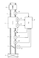
- FIG. 1 is a diagram showing an overall configuration of an internal combustion engine and its fuel injection control system according to an embodiment of the present invention.
- An intake pipe 2 and an exhaust pipe 7 are connected to the engine 1, and an air cleaner 3 is provided on the upstream side of the intake pipe 2.
- the amount of intake air to the engine 1 is adjusted by a throttle valve 4 disposed inside the intake pipe 2.
- the opening of the throttle valve 4 is detected by a throttle opening sensor (hereinafter referred to as a TH sensor) 11.
- the intake pipe absolute pressure sensor (hereinafter referred to as PBA sensor) 12 measures the intake pipe absolute pressure PBA.
- An intake air temperature sensor (hereinafter referred to as a TA sensor) 16 measures an intake air temperature TA inside the intake pipe 2.
- a water temperature sensor (hereinafter referred to as a TW sensor) 13 measures the cooling water temperature TW of the engine 1.
- a crank angle sensor (hereinafter referred to as a CRK sensor) 14 measures a crank angle CRK representing the crank position of the engine 1.
- a three-way catalyst 8 is provided on the downstream side of the exhaust pipe 7, and an oxygen concentration for measuring the oxygen concentration of the exhaust gas in the exhaust pipe 7 is between the engine 1 and the three-way catalyst 8 in the exhaust pipe 7.
- a sensor hereinafter referred to as an O2 sensor 15 is provided.
- An engine control unit (ECU: Electronic Control Unit) 10 executes various engine controls including fuel injection control based on the detection signals output from the sensors described above.
- the injector 5 opens in response to an injection control signal output from the ECU 10 and injects gasoline or a mixed fuel of gasoline and alcohol (ethanol in this embodiment).
- FIG. 2 is a functional block diagram showing the configuration of the main part of the ECU 10, and the same reference numerals as those described above represent the same or equivalent parts. Here, illustrations of structures that are not necessary for the description of the present invention are omitted.
- the ECU 10 includes a CPU 21, a RAM 22 that provides a work area to the CPU 21, programs executed by the CPU 21 and information for injection control (Pb / Ne map, Ne / TH map, various correction coefficient tables, start control described later) Information) and the like, and a EEP-ROM 24 in which various control parameters including a setting set, which will be described later, are rewritable and nonvolatilely stored.
- the CPU 21 and the storage elements 22, 23, 24 are connected to each other by an internal bus.
- FIG. 3 is a diagram schematically showing the storage contents of the ROM 23.
- a Pb / Ne map, a Ne / TH map, various correction coefficient tables, and start control information are stored in association with each other.
- ethanol contains oxygen atoms in its composition, and the amount of oxygen per unit volume required for combustion is less than that required when gasoline is burned.
- the stoichiometric air-fuel ratio is smaller than when using only gasoline fuel. Therefore, in order to operate the engine 1 in an optimum state, it is necessary to set injection control information for each mixing ratio of ethanol and gasoline.
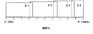
- the ethanol concentration ranges are set as shown in FIG. 4 as an example, and E1, E2, E3, E4 (the alcohol concentration is E1 ⁇ E2 ⁇ Four types of E3 ⁇ E4) are determined in advance, and a Pb / Ne map, a Ne / TH map, various correction coefficient tables, and start control information are prepared for each reference concentration.
- the reference concentration may be any number as long as it is three or more, and may be appropriately assigned to any concentration from 0% to 100%.
- Each map and table is set so as to have overlapping ranges as densities as shown in FIG.
- a set of Pb / Ne map, Ne / TH map, various correction coefficient tables and start injection information prepared for each ethanol reference concentration is expressed as a “map set”, and each ethanol reference concentration map set May be expressed as an E1 map set, an E2 map set, an E3 map set, and an E4 map set, respectively.
- the calculation process of the injected fuel amount by the ECU 10 is roughly divided into “starting injection control” and “normal operation injection control”.
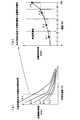
- the starting injection time TICR for injecting fuel into the injector 5 at the time of starting the engine is uniquely determined by the coolant temperature TW of the cooling water of the engine 1. Specifically, as shown in an example in FIG. 5, the correspondence relationship between the water temperature TW and the start injection time TICR is stored in the ROM 23 in advance as a start injection table, and based on the water temperature TW detected at the start. The start injection time TICR is obtained by referring to the start injection table.
- the optimal injection time varies depending on the ethanol concentration even when the water temperature TW is constant. It is necessary to set an injection time such that maximum fuel injection can be performed when the ethanol concentration is high while preventing excessive fuel injection when the fuel concentration is low. Therefore, in this embodiment, a concentration range as shown in FIG. 6B is set, and a start injection table is prepared for each of the ethanol reference concentrations E1, E2, E3, and E4.
- the increase width ⁇ ti of the start injection time as a constant, the number N of repetitions indicating the number of times that the injection time is increased by the increase width when the number of injections is performed, the start The upper limit value Tmax of the injection time is associated.
- the values of these constants are also stored in the ROM 23 in advance in the present embodiment.
- the start injection table and these constants may be expressed as start injection information.
- the intake air amount under various conditions is obtained by referring to a Pb / Ne map or Ne / TH map obtained in advance based on experimental results.
- a basic fuel injection time TIM is calculated based on the intake air amount and the target air-fuel ratio.
- FIG. 7A shows an example of the Pb / Ne map
- FIG. 7B shows an example of the Ne / TH map.
- the Pb / Ne map is a map used in an intake oxygen amount estimation method called a speed density method that is employed during low load operation such as idling, and is based on the intake pipe absolute pressure PBA and the engine speed Ne based on the map.
- the amount of intake air is determined. As shown in FIG. 7 (a), there is no fixed correlation between PBA and Ne, and the intake air amount is specified as an iso air amount diagram.
- the Ne / TH map is a map used in an intake oxygen amount estimation method called a throttle speed method that is used during high-load operation, and the intake air is based on the engine rotational speed Ne and the throttle opening TH. A quantity is required.
- FIG. 7 (b) in the Ne / TH map, similar to the Pb / Ne map, there is no fixed correlation between Ne and TH, and the intake air amount is specified as an iso-air diagram. Will be.
- the ethanol reference concentrations (E1, E2, E3 , E4), Ne / TH map and Pb / Ne map are prepared.
- FIG. 8 is a diagram showing an example of a correction coefficient table for obtaining the intake air temperature correction coefficient KTA corresponding to the intake air temperature TA obtained from the measurement result of the TA sensor 16.
- correction coefficients there are correction coefficients based on measured values obtained from the TH sensor 11, TW sensor 13, CRK sensor 14, and O2 sensor 15, respectively.
- the increase correction coefficient KAST after starting, the water temperature There are correction coefficients such as correction coefficient KTW, acceleration correction coefficient TACC, and ignition timing coefficient FICSTG.
- a correction coefficient table exists for each of these correction coefficients, and each correction coefficient table is prepared for each ethanol reference concentration (E1, E2, E3, E4).
- the injection amount of the ethanol mixed fuel increases as compared with the injection amount of gasoline. If the mixed fuels are compared, the injection amount increases as the ethanol concentration increases. For this reason, if fuel injection is started at the same injection timing as when the fuel is gasoline, the end timing of the injection is delayed.
- a correction coefficient table is prepared for each ethanol reference concentration (E1, E2, E3, E4), and the injection start timing is advanced according to the ethanol concentration.
- FIG. 9 is a diagram comparing the injection timing and injection period of fuel with an ethanol concentration of E1 (FIG. 9A) and the injection timing and injection period of fuel with an ethanol concentration of E4 [FIG. .
- a correction coefficient table is prepared for each ethanol reference concentration so that the injection timing becomes earlier as the ethanol concentration becomes higher and the injection period becomes longer.
- the correction time is set for each engine speed NE. Is set.
- FIG. 10 is a block diagram functionally representing the configuration of the fuel injection control device of the present invention, and the same reference numerals as those described above represent the same or equivalent parts.
- the O2 concentration coefficient calculation unit 100 calculates an oxygen concentration coefficient KO2 for maintaining the theoretical air-fuel ratio, based on the measured value (voltage) VO2 of the O2 sensor 15 representing the oxygen concentration in the exhaust pipe 7. It is known that this oxygen concentration coefficient KO2 is substantially proportional to the ethanol concentration of fuel. Further, since the oxygen concentration coefficient KO2 vibrates due to a change with time or external influence during the operation of the engine 1, the O2 concentration coefficient calculation unit 100 further calculates a learning average value (moving average value) KO2REF of the oxygen concentration coefficient KO2. For example, it is calculated based on the following formula (1).
- KO2REF n-1 is the previous learning average value.
- ⁇ is an averaging coefficient, and is usually set to a value of about 0.1.
- the first map switching unit 101 compares the ethanol concentration corresponding to the learned average value KO2REF and the reference concentration of the currently referenced fuel injection map, and if the current fuel injection map does not match the learned average value KO2REF.
- the fuel injection map is switched to the high concentration side or the low concentration side.
- the learned average value KO2REF indicates a large value when the oxygen concentration in the exhaust gas is high, and indicates a small value when the oxygen concentration in the exhaust gas is low. Therefore, if KO2REF is large, it is determined that the ethanol concentration of the fuel is high, and processing for switching to a map having a high ethanol concentration is performed. On the other hand, if KO2REF is small, it is determined that the ethanol concentration of the fuel is low, and processing for switching to a map with a low ethanol concentration is performed.
- the second map switching unit 102 compares the measured value VO2 of the O2 sensor 15 with a predetermined reference value VO2ref. Switch to.
- the engine load detection unit 103 detects the current engine load based on the engine speed Ne and the throttle opening TH.
- the switching selection unit 104 selects one of the first and second map switching units 101 and 102 based on the engine load determination result.
- the selected map switching unit performs map switching based on the measured value VO2 of the O2 sensor 15 or the learning average value KO2REF.
- the fuel injection amount control unit 105 determines the fuel injection amount by applying engine parameters to the fuel injection map switched by the selected map switching unit.
- FIG. 11 is a main flow of fuel injection control, which is repeatedly executed at a predetermined cycle after the main switch (SW) is turned on.
- SW main switch
- start injection control is executed in step S1.
- FIG. 12 is a flowchart showing the procedure of the starting injection control.
- step S101 the setting set registered in the EEP-ROM 24 is read. This setting set is data for starting injection control stored during the previous operation, and will be described in detail later with reference to the flowchart of FIG.
- step S102 start injection information is extracted from the read setting set, and based on the start injection table included in the start injection information and the coolant temperature TW detected by the TW sensor 13, the start injection time is determined. The initial value of TICR is obtained. Further, the increase width ⁇ ti, the number of repetitions N, and the start injection time upper limit value Tmax included in the start injection information are also extracted. Further, the starting injection number n is reset.
- step S103 it is determined whether or not the engine is cranking. If not, the determination is continued until cranking is started. Thereafter, when it is determined that cranking is being performed, the process proceeds to step S104, where the number of start injections n is incremented.
- step S105 the start injection time TICR is compared with the start injection time upper limit value Tmax. If the start injection time TICR is less than the start injection time upper limit value Tmax, the process proceeds to step S106.
- step S106 the start injection number n is compared with the repetition number N, and if the start injection number n is equal to the repetition number N, the process proceeds to step S107.
- step S107 the increment width ⁇ ti is added to the current TICR to obtain a new TICR.
- step S108 the starting injection number n is reset.
- step S109 the current engine speed (Ne) calculated based on the measured value of the CRK sensor 14 is compared with the reference speed A for start determination, and the engine speed (Ne) exceeds the reference speed A. If so, it is determined that the start is complete, and the process is terminated.
- step S105 If it is determined in step S105 that the start injection time TICR is not less than the injection time upper limit value Tmax, or if it is determined in step S106 that the start injection number n is not equal to the number N of repetitions, the current start While maintaining the injection time TICR, the routine proceeds to step S109, where the completion of the start is determined.
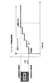
- FIG. 16 is a diagram showing a change in the starting injection time TICR when the number of repetitions N is set to 4 in the process of FIG. 12, and the TICR increases stepwise by ⁇ ti every time four injections are performed.
- the starting injection time reaches Tmax, cranking is continued in a state where the TICR is maintained.
- the minimum value at which the ICCR changes is the minimum required injection amount (lower limit concentration required injection amount) at the reference ethanol concentration set in the setting set, and the maximum value is the maximum required injection at the ethanol concentration.
- ⁇ ti and the number of repetitions N are determined in advance such that the amount (the upper limit concentration required injection amount) is reached.
- the starting control can be performed by gradually increasing, that is, by gradually increasing the fuel injection amount injected from the injector 5.
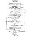
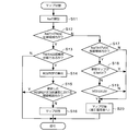
- step S201 map switching for selecting an optimal fuel injection map for the ethanol concentration of the fuel is executed. That is, any one of an E1 map, an E2 map, an E3 map, and an E4 map is selected as a map for calculating the basic injection amount TIM optimum for the current engine state.
- FIG. 14 is a flowchart showing the map switching procedure.
- the engine speed (Ne) is calculated based on the detection signal of the CRK sensor 14.
- the calculated engine speed (Ne) and the throttle opening (TH) obtained from the detection signal of the TH sensor 11 are within the normal load region (map switching region based on the learning average value KO2REF) shown in FIG. It is determined whether or not there is.
- step S13 the engine 1 is in a warm-up state, that is, normally, based on the water temperature TW obtained from the detection signal of the TW sensor 13 and the intake air temperature TA obtained from the detection signal of the TA sensor 16. It is determined whether or not it is in an operating state. If it is determined that the engine is not warmed up, the process ends without switching the fuel injection map.
- step S14 the learning average value KO2REF is calculated by performing the moving average calculation of the above equation (1) for the oxygen concentration coefficient KO2 obtained from the measured value VO2 of the O2 sensor 15, and this calculation result is Updated and registered as a new KO2REF.
- the threshold values for the reference density are upper and lower threshold values set for each reference density, as shown in FIG.
- the threshold is adjusted and set so that the maps overlap each other.
- the lower limit threshold is 0 and the upper limit threshold is 1.2.
- the lower limit threshold is 0.8 and the upper limit threshold is 1.2.
- the lower limit threshold is 0.8 and the upper limit threshold is 1.2.
- the E4 map only the lower threshold value is set, and the value is 0.8.
- the process proceeds to step S16 to switch to the E1 map.
- KO2REF is a value exceeding 1.2, the process proceeds to step S16 to switch to the E3 map.
- step S12 determines whether NE / TH is outside the KO2 control region. If it is determined in step S12 that NE / TH is outside the KO2 control region, the process proceeds to step S17.
- step S17 it is determined whether NE / TH is within a high load area (map switching area by VO2). If it is outside the high load region, the process ends without switching the fuel injection map.
- step S18 it is determined whether or not the current reference map is E3 or E4. If a map of E3 or higher has already been referenced, the process is terminated without switching the fuel injection map. On the other hand, if the current reference map is less than E3, the process proceeds to step S19.
- step S19 it is determined whether or not the measured value VO2 of the O2 sensor 15 is equal to or lower than the reference voltage VO2ref. In the present embodiment, if the measured value VO2 is not 0.2 V or less, the process is terminated without switching the fuel injection map. On the other hand, if VO2 is 0.2 V or less, it is determined that the engine is over lean, and the process proceeds to step S20, where the map is switched to a map on the higher E side than the current map. That is, if the current reference density is E2, the map is switched to E3.
- step S202 Using the map set determined as described above, the basic fuel injection time TIM is determined using the engine speed Ne and the intake pressure Pb as engine parameters. Calculated.
- step S203 the measured values obtained from the sensors such as the TH sensor 11, TW sensor 13, CRK sensor 14, and O2 sensor 15 are applied to the corresponding table of the map set, and the post-startup increase correction coefficient (KAST) and water temperature correction are performed. Correction coefficients such as a coefficient (KTW) and an acceleration correction coefficient (TACC) are calculated.
- KAST post-startup increase correction coefficient
- TACC acceleration correction coefficient
- step S204 the fuel injection time Tout after correction is calculated by multiplying or adding each correction coefficient to the basic fuel injection amount TIM in the same manner as in the prior art to calculate the final fuel injection time Tout in consideration of the invalid time of the injector 5 and the like.
- the fuel injection amount (time) is determined.
- step S2 when the normal operation injection control in step S2 is completed as described above, the process proceeds to step S3 and the preparation process for starting injection is executed.
- FIG. 15 is a flowchart showing the procedure of the start injection preparation process.
- the oxygen concentration coefficient KO2 is calculated based on the measured value VO2 of the O2 sensor 15, and the oxygen concentration coefficient KO2 is calculated from the above equation (1). Is applied to the learning average value KO2REF.
- the ethanol concentration of the fuel is estimated based on the ethanol concentration and the learning average value KO2REF shown in FIG. 4, and one of the E1 map, E2 map, E3 map, and E4 map is estimated based on the estimation result. Is selected.
- step S303 the selected map and reference density are updated and registered in the EEP-ROM 24 as a setting set. Since this setting set is stored in a nonvolatile manner, when the main SW is turned on again after being shut off, it is read out in step S101 of step S12 and used in the next start injection control.
Landscapes
- Engineering & Computer Science (AREA)
- Chemical & Material Sciences (AREA)
- Combustion & Propulsion (AREA)
- Mechanical Engineering (AREA)
- General Engineering & Computer Science (AREA)
- Oil, Petroleum & Natural Gas (AREA)
- Electrical Control Of Air Or Fuel Supplied To Internal-Combustion Engine (AREA)
- Combined Controls Of Internal Combustion Engines (AREA)
- Output Control And Ontrol Of Special Type Engine (AREA)
Abstract
Description

エンジン負荷検知部103は、エンジン回転数Neおよびスロットル開度THに基づいて現在のエンジン負荷を検知する。切替選択部104は、前記エンジン負荷の判定結果に基づいて第1および第2マップ切替部101,102の一方を選択する。選択されたマップ切替部は、O2センサ15の計測値VO2またはその学習平均値KO2REFに基づいてマップ切替を実行する。燃料噴射量制御部105は、選択されているマップ切替部により切り替えられた燃料噴射マップにエンジンパラメータを適用して燃料噴射量を決定する。
Claims (4)
- エンジンへのアルコール混合燃料の噴射量を排気ガス中の酸素濃度に基づいて制御する燃料噴射制御装置において、
排気ガス中の酸素濃度に応じた信号を出力する酸素濃度センサと、
燃料のアルコール濃度ごとに設けられ、エンジンの運転状態と燃料噴射量との関係を定めた複数の燃料噴射マップと、
前記酸素濃度センサの出力を所定の期間だけ学習して酸素濃度を算出する手段と、
前記酸素濃度に基づいて燃料噴射マップを切り替える第1切替手段と、
前記酸素濃度センサの出力に基づいて燃料噴射マップを切り替える第2切替手段と、
エンジンの負荷状態に基づいて第1および第2切替手段の一方を選択する選択手段と、
前記選択されている切替手段により切り替えられた燃料噴射マップにエンジンの運転状態を適用して燃料噴射量を決定する燃料噴射量決定手段とを含むことを特徴とする多種燃料エンジンの燃料噴射制御装置。 - 前記第2切替手段は、前記酸素濃度センサから出力される信号そのものに基づいて燃料噴射マップを切り替えることを特徴とする請求項1に記載の多種燃料エンジンの燃料噴射制御装置。
- 前記第2切替手段は、スロットル開度が所定の基準値よりも大きい場合に燃料噴射マップを切り替えることを特徴とする請求項2に記載の多種燃料エンジンの燃料噴射制御装置。
- 前記第2切替手段は、排気ガス中の酸素濃度が高いときに、燃料噴射マップをより高アルコール濃度側の燃料噴射マップに切り替えることを特徴とする請求項3に記載の多種燃料エンジンの燃料噴射制御装置。
Priority Applications (1)
| Application Number | Priority Date | Filing Date | Title |
|---|---|---|---|
| BRPI0909364-8A BRPI0909364B1 (pt) | 2008-03-31 | 2009-02-26 | Dispositivo de controle de injeção de combustível de motor de multicombustível |
Applications Claiming Priority (2)
| Application Number | Priority Date | Filing Date | Title |
|---|---|---|---|
| JP2008093026A JP4945816B2 (ja) | 2008-03-31 | 2008-03-31 | 多種燃料エンジンの燃料噴射制御装置 |
| JP2008-093026 | 2008-03-31 |
Publications (1)
| Publication Number | Publication Date |
|---|---|
| WO2009122829A1 true WO2009122829A1 (ja) | 2009-10-08 |
Family
ID=41135225
Family Applications (1)
| Application Number | Title | Priority Date | Filing Date |
|---|---|---|---|
| PCT/JP2009/053590 Ceased WO2009122829A1 (ja) | 2008-03-31 | 2009-02-26 | 多種燃料エンジンの燃料噴射制御装置 |
Country Status (3)
| Country | Link |
|---|---|
| JP (1) | JP4945816B2 (ja) |
| BR (1) | BRPI0909364B1 (ja) |
| WO (1) | WO2009122829A1 (ja) |
Cited By (1)
| Publication number | Priority date | Publication date | Assignee | Title |
|---|---|---|---|---|
| US20130151117A1 (en) * | 2011-12-08 | 2013-06-13 | Kia Motors Corp. | Method of determining water content of ethanol for ffv and correcting fuel quantity based on water content |
Families Citing this family (5)
| Publication number | Priority date | Publication date | Assignee | Title |
|---|---|---|---|---|
| JP2013217201A (ja) * | 2012-04-04 | 2013-10-24 | Toyota Motor Corp | 内燃機関 |
| JP5925183B2 (ja) * | 2013-09-30 | 2016-05-25 | 本田技研工業株式会社 | 混合燃料車両用空燃比制御装置 |
| DE102016208086A1 (de) * | 2016-05-11 | 2017-11-16 | Robert Bosch Gmbh | Verfahren zur Regelung eines Injektors zur Einspritzung von Kraftstoff |
| CN108087135B (zh) * | 2017-12-15 | 2020-09-04 | 奇瑞汽车股份有限公司 | 双燃料车辆的控制方法和装置 |
| JP7727602B2 (ja) * | 2022-09-08 | 2025-08-21 | 本田技研工業株式会社 | 内燃機関の燃料噴射制御装置 |
Citations (4)
| Publication number | Priority date | Publication date | Assignee | Title |
|---|---|---|---|---|
| JPH0791283A (ja) * | 1993-09-22 | 1995-04-04 | Nissan Motor Co Ltd | エンジンの燃料噴射制御装置 |
| JP2005127192A (ja) * | 2003-10-22 | 2005-05-19 | Toyota Motor Corp | 内燃機関の燃料噴射制御装置 |
| JP2006077683A (ja) * | 2004-09-10 | 2006-03-23 | Nissan Motor Co Ltd | エンジンのアルコール濃度推定装置 |
| JP2007146831A (ja) * | 2005-10-27 | 2007-06-14 | Nissan Motor Co Ltd | 内燃機関の制御装置 |
-
2008
- 2008-03-31 JP JP2008093026A patent/JP4945816B2/ja not_active Expired - Fee Related
-
2009
- 2009-02-26 BR BRPI0909364-8A patent/BRPI0909364B1/pt active IP Right Grant
- 2009-02-26 WO PCT/JP2009/053590 patent/WO2009122829A1/ja not_active Ceased
Patent Citations (4)
| Publication number | Priority date | Publication date | Assignee | Title |
|---|---|---|---|---|
| JPH0791283A (ja) * | 1993-09-22 | 1995-04-04 | Nissan Motor Co Ltd | エンジンの燃料噴射制御装置 |
| JP2005127192A (ja) * | 2003-10-22 | 2005-05-19 | Toyota Motor Corp | 内燃機関の燃料噴射制御装置 |
| JP2006077683A (ja) * | 2004-09-10 | 2006-03-23 | Nissan Motor Co Ltd | エンジンのアルコール濃度推定装置 |
| JP2007146831A (ja) * | 2005-10-27 | 2007-06-14 | Nissan Motor Co Ltd | 内燃機関の制御装置 |
Cited By (1)
| Publication number | Priority date | Publication date | Assignee | Title |
|---|---|---|---|---|
| US20130151117A1 (en) * | 2011-12-08 | 2013-06-13 | Kia Motors Corp. | Method of determining water content of ethanol for ffv and correcting fuel quantity based on water content |
Also Published As
| Publication number | Publication date |
|---|---|
| BRPI0909364B1 (pt) | 2019-02-19 |
| BRPI0909364A2 (pt) | 2015-09-29 |
| JP2009243408A (ja) | 2009-10-22 |
| JP4945816B2 (ja) | 2012-06-06 |
Similar Documents
| Publication | Publication Date | Title |
|---|---|---|
| JP5009891B2 (ja) | 多種燃料エンジンの燃料噴射制御装置 | |
| JP3259967B2 (ja) | 燃料と空気の混合気を適応調節する方法 | |
| US6975933B2 (en) | Fuel properties estimation for internal combustion engine | |
| US6298838B1 (en) | Ethanol content learning based on engine roughness | |
| JP5042105B2 (ja) | 多種燃料エンジンの燃料噴射制御装置 | |
| US7567866B2 (en) | Fuel injection control device | |
| JP3903943B2 (ja) | 内燃機関の燃料性状推定装置 | |
| US20090107441A1 (en) | Adaptive fuel control strategy for engine starting | |
| JP4945816B2 (ja) | 多種燃料エンジンの燃料噴射制御装置 | |
| JP2010043531A (ja) | 内燃機関の燃料噴射制御装置 | |
| CN107061025B (zh) | 利用可变电压氧传感器估计空燃比的方法和系统 | |
| JPH04159432A (ja) | 電子制御燃料噴射装置 | |
| WO2006129198A1 (en) | Fuel injection quantity control apparatus for an internal combustion engine | |
| JP3903925B2 (ja) | 内燃機関の燃料性状推定装置 | |
| US8161954B2 (en) | Fuel supply control apparatus | |
| JP3966202B2 (ja) | 内燃機関の制御装置 | |
| JP3863362B2 (ja) | 内燃機関の制御装置 | |
| JP4010256B2 (ja) | 内燃機関の制御装置 | |
| JP5333361B2 (ja) | 内燃機関燃料噴射制御装置 | |
| JP5056640B2 (ja) | エンジンの燃料供給システム | |
| JP2010031804A (ja) | フレキシブル燃料機関の燃料噴射制御装置 | |
| JP2004293491A (ja) | 内燃機関の制御装置 | |
| JP2009121399A (ja) | 内燃機関の燃料アルコール濃度推定装置 | |
| JPH0629588B2 (ja) | 内燃機関の空燃比制御装置 | |
| JPH07324643A (ja) | 内燃機関の燃料噴射制御装置 |
Legal Events
| Date | Code | Title | Description |
|---|---|---|---|
| 121 | Ep: the epo has been informed by wipo that ep was designated in this application |
Ref document number: 09726855 Country of ref document: EP Kind code of ref document: A1 |
|
| WWE | Wipo information: entry into national phase |
Ref document number: 6130/CHENP/2010 Country of ref document: IN |
|
| NENP | Non-entry into the national phase |
Ref country code: DE |
|
| 122 | Ep: pct application non-entry in european phase |
Ref document number: 09726855 Country of ref document: EP Kind code of ref document: A1 |
|
| ENP | Entry into the national phase |
Ref document number: PI0909364 Country of ref document: BR Kind code of ref document: A2 Effective date: 20100929 |