WO2009122941A1 - Bougie d'allumage - Google Patents
Bougie d'allumage Download PDFInfo
- Publication number
- WO2009122941A1 WO2009122941A1 PCT/JP2009/055683 JP2009055683W WO2009122941A1 WO 2009122941 A1 WO2009122941 A1 WO 2009122941A1 JP 2009055683 W JP2009055683 W JP 2009055683W WO 2009122941 A1 WO2009122941 A1 WO 2009122941A1
- Authority
- WO
- WIPO (PCT)
- Prior art keywords
- resistor
- conductive glass
- spark plug
- seal layer
- glass seal
- Prior art date
- Legal status (The legal status is an assumption and is not a legal conclusion. Google has not performed a legal analysis and makes no representation as to the accuracy of the status listed.)
- Ceased
Links
Images


Classifications
-
- H—ELECTRICITY
- H01—ELECTRIC ELEMENTS
- H01T—SPARK GAPS; OVERVOLTAGE ARRESTERS USING SPARK GAPS; SPARKING PLUGS; CORONA DEVICES; GENERATING IONS TO BE INTRODUCED INTO NON-ENCLOSED GASES
- H01T13/00—Sparking plugs
- H01T13/20—Sparking plugs characterised by features of the electrodes or insulation
- H01T13/34—Sparking plugs characterised by features of the electrodes or insulation characterised by the mounting of electrodes in insulation, e.g. by embedding
-
- H—ELECTRICITY
- H01—ELECTRIC ELEMENTS
- H01T—SPARK GAPS; OVERVOLTAGE ARRESTERS USING SPARK GAPS; SPARKING PLUGS; CORONA DEVICES; GENERATING IONS TO BE INTRODUCED INTO NON-ENCLOSED GASES
- H01T13/00—Sparking plugs
- H01T13/20—Sparking plugs characterised by features of the electrodes or insulation
Definitions
- the present invention relates to a spark plug used in an internal combustion engine, and more particularly to a spark plug in which a resistor is incorporated.
- a spark plug incorporating a resistor has a cylindrical insulator, and a through hole is formed in the insulator along the axial direction.
- a metal terminal fitting is inserted and fixed from one end side, and a metal center electrode is inserted and fixed to the other end side, and between the terminal fitting and the center electrode in this through hole.
- a structure in which a resistor is arranged is known (for example, see Patent Document 1).
- This resistor is made of a mixture of glass powder and a conductive material such as carbon black powder or metal powder, but the metal content is not so high. For this reason, it is often difficult to directly join a metal terminal fitting or a center electrode. For this reason, in general, a conductive glass made of a mixture of a relatively large amount of metal powder and glass powder between them.
- positioned the sealing layer and improved the joining force is employ
- Such a spark plug containing a resistor is manufactured as follows. First, the center electrode is inserted and fixed in the through-hole of the insulator, then filled with conductive glass powder, then filled with the raw material powder of the resistor composition, further filled with conductive glass powder, and finally the center. A terminal fitting is press-fitted from the opposite side of the electrode to create an assembly. Next, this assembly is carried into a heating furnace and heated to the glass softening point or more, and the layers are compressed by pushing the terminal fitting in the axial direction of the terminal fitting. Thus, the conductive glass seal layer on the center electrode side and the conductive glass seal layer on the resistor and terminal fitting side are obtained. The terminal fitting and the center electrode are bonded to the resistor via the conductive glass seal layer and fixed to the insulator (hereinafter, the process of forming each layer is also referred to as a “layer formation process”). To tell.).
- a metal layer made of a specific material is provided in a surface layer region of a portion in contact with the conductive glass seal layer of the terminal metal fitting to increase the bonding force between the terminal metal fitting and the conductive glass seal layer. This prevents problems such as deterioration of the bonding state.
- the resistor and the conductive glass seal layer particularly the junction between the resistor and the conductive glass seal layer
- the resistance of the conventional spark plug in which the diameter of the through-hole is approximately 3.9 mm has not been a problem when vibrations and shocks from the engine act on the spark plug. In some cases, peeling may occur on the joint surface of the conductive glass seal layer, making it difficult to obtain electrical continuity.
- the spark plug described in Patent Document 1 is provided with a metal layer made of a specific material in the surface layer region of the terminal fitting, and increases the bonding force between the terminal fitting and the conductive glass seal layer, This is a technique different from the present invention for the purpose of reducing the diameter of the spark plug.
- the present invention has been made in view of the above-mentioned problems, and its purpose is to enhance the adhesion between the resistor and the conductive glass seal layer, and to have excellent vibration resistance and resistor load life characteristics, and The object is to provide a spark plug with a reduced diameter.
- a spark plug having the following configuration.
- the through hole is formed so that its radial cross section is circular,
- the axial distance L between the center electrode and the terminal fitting is 16 mm or less, DR 2 / M, where DR is the maximum diameter of the resistor, and M is the shortest length in the axial direction of the portion of the resistor in which only the resistor is provided in the through hole without a gap.
- the spark plug according to any one of the above (1) to (4), wherein is 2.2 or less.
- the terminal fitting and the resistor are spaced apart,
- the second conductive glass seal layer is provided in the through hole without a gap between the terminal fitting and the resistor, Any one of the above (1) to (5), wherein the second bonding surface of the resistor and the second conductive glass seal layer is formed in a curved shape, and the top thereof faces the center electrode. Spark plugs.
- the surface area of the second joint surface is Sb, and the cross-sectional area of the cross section of the second conductive glass seal layer that is orthogonal to the axial direction and includes the edge of the joint surface is S2.
- Sb / S2 is 1.1 or more.
- the surface area of the second joint surface is Sb, and the cross-sectional area of the cross section of the second conductive glass seal layer that is orthogonal to the axial direction and includes the edge of the joint surface is S2.
- the conductive glass seal layer is formed from a mixture containing glass powder and metal powder,
- the resistor is formed from a mixture including glass powder, ceramic powder, and non-metallic conductive powder;
- the resistor and the center electrode are joined together by the conductive glass seal layer provided therebetween.
- the diameter D of the conductive glass seal layer bonded to the resistor is in the range of 3.3 mm or less (D ⁇ 3.3 mm), and the bonding surface with the resistor is formed in a curved shape. Even if the diameter D of the layer is reduced, the area of the joint surface between the conductive glass seal layer and the resistor can be increased. As a result, the bonding force of the bonding surface is increased to the same level as or higher than that of the conventional one to prevent the occurrence of defects such as peeling on the bonding surface due to vibration or impact applied to the spark plug, and poor conduction. Can improve the reliability.
- the degree of freedom in engine design is increased and the size can be reduced.
- the joining surface should just be formed in the curved surface form, for example, can include a bowl-shaped curved surface, a curved surface with several unevenness
- the spark plug is further provided.
- Sa / S1 when the surface area of the joint surface between the conductive glass seal layer and the resistor is Sa and the cross-sectional area of the conductive glass seal layer is S1, Sa / S1 is 1. Since it is 1 or more (Sa / S1 ⁇ 1.1), the area of the joint surface between the conductive glass seal layer and the resistor should be widened despite the small diameter D of the conductive glass seal layer. Therefore, the joining force can be increased to the same level or higher. In order to further increase the bonding force, the configuration (4), Sa / S1, is preferably 1.5 or more (Sa / S1 ⁇ 1.5).
- the axial distance L between the center electrode and the terminal fitting is 16 mm or less (L ⁇ 16 mm), for example, even in a spark plug in which the diameter of the resistor is reduced to 3 mm or less, The impact on the joint surface between the conductive glass seal layer and the resistor due to impact can be prevented over a long period of time, and a small and long-life spark plug can be provided.
- the configuration of (6) above since the second bonding surface between the resistor and the second conductive glass seal layer is formed in a curved shape, the second conductive glass seal layer, the resistor, The area of the second joint surface can be increased.
- the vibration applied to the spark plug by increasing the bonding force between the second conductive glass seal layer and the resistor to the same level as or higher than the conventional one. It is possible to increase the reliability of the spark plug by preventing the occurrence of defects such as peeling or poor conduction at the second joint due to impact or the like.
- the surface area of the second joint surface between the second conductive glass seal layer and the resistor is Sb
- the cross-sectional area of the second conductive glass seal layer is S2.
- the second conductive glass seal is formed despite the small diameter of the second conductive glass seal layer.
- the area of the second bonding surface between the layer and the resistor is large, and the bonding force at the bonding surface can be increased to the same level or higher.
- the configuration (8), Sb / S2, is preferably 1.5 or more (Sb / S2 ⁇ 1.5).
- the conductive glass seal layer is formed from a mixture including glass powder and metal powder
- the resistor is formed from a mixture including glass powder, ceramic powder, and non-metallic conductive powder.
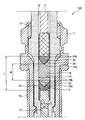
- FIG. 1 It is sectional drawing of the spark plug of this invention. It is a principal part enlarged view of the spark plug in FIG. It is a conceptual diagram which compares and shows the numerical value of Sa / S1 calculated
- FIG. 1 is a cross-sectional view of the spark plug of the present invention.
- FIG. 2 is an enlarged view of a main part of the spark plug in FIG.
- a spark plug 100 As shown in FIGS. 1 and 2, a spark plug 100 according to the present invention includes a cylindrical metal shell 11, a through hole 16 formed along the axial direction of the metal shell 11, and both end portions 12a. , 12b is fitted into and held in the metal shell 11 so that the metal shell 11 is exposed, and one end of the through-hole 16 (lower in the figure) so that the tip 13a is exposed.
- the center electrode 13 inserted and fixed to 16a, the terminal fitting 17 inserted and fixed to the other end (upper in the drawing) 16b of the through hole 16 so that the rear end 17a is exposed, and the center in the through hole 16
- a resistor 18 provided between the electrode 13 and the terminal fitting 17 and spaced apart in the axial direction from each of the center electrode 13 and the terminal fitting 17, and the resistor 18 and the center electrode 13 in the through hole 16 No gap between In the metal shell 11, the first conductive glass seal layer 19, the second conductive glass seal layer 20 provided between the resistor 18 and the terminal fitting 17 in the through hole 16 without a gap, and the metal shell 11.
- a substantially L-shaped ground electrode 14 having one end portion (base portion) 14a coupled thereto by resistance welding or the like, the intermediate portion 14c being bent, and the other end portion 14b being opposed to the tip end portion 13a of the center electrode 13; ing.
- the side on which the center electrode 13 is arranged in the axial direction of the metal shell 11 will be described as the front side, and the opposite side (side on which the terminal metal fitting is arranged) will be described as the rear side.
- the metal shell 11 is made of carbon steel or the like, and a male screw 15 for mounting to be attached to a cylinder head (a mating member) of an internal combustion engine such as an engine is formed on the outer peripheral surface of the metal shell 11 in the circumferential direction.
- the female screw 15 is set to M10 or less in order to reduce the diameter.
- the insulator 12 is formed from a ceramic fired body such as alumina.
- the through-hole 16 is formed so that the radial cross section thereof has a substantially uniform circular shape in the axial direction, and the inner diameter of the through-hole 16 is set in a range of 1.9 mm or more and 3.3 mm or less. .
- Only the portion on the front side of the through-hole 16 has a stepped portion and is reduced in diameter ⁇ in the drawing, the inner diameter of this portion is shown as d1 (see FIG. 2). ⁇ .
- a resistor 18 is disposed between the terminal fitting 17 and the center electrode 13 in the through hole 16, and first and second conductive glass seal layers 19 are provided at both ends of the resistor 18. , 20 are respectively disposed, the resistor 18 is electrically connected to the center electrode 13 and the terminal fitting 17 through the first and second conductive glass seal layers 19, 20.
- the conductive glass seal layers 19 and 20 and the resistor 18 form a conductive bonding layer, and the composition thereof will be described later.
- the center electrode 13 is formed in a columnar shape by a Ni alloy having excellent heat resistance and corrosion resistance such as Inconel (trade name), and the tip of the center electrode 13 has, for example, 5 masses containing iridium as a main component.
- a cylindrical noble metal tip 21 made of an alloy containing 1% platinum (Ir-5Pt) is fixed by laser welding or the like.
- the inner diameter (the inner diameter of the reduced diameter portion) d1 of the through hole 16 of the insulator 12 is slightly larger than the outer diameter D1 of the center electrode 13, and the distance between the center electrode 13 and the through hole 16 is, for example, 0.
- a radial gap C of 1 to 0.5 mm is provided.
- the radial gap C is provided as a gap for avoiding a difference in thermal expansion due to different thermal expansion coefficients between the center electrode 13 and the insulator 12.
- the ground electrode 14 is formed in a substantially prismatic shape from a Ni alloy having excellent heat resistance and corrosion resistance.
- platinum is used as a main component and Rh or Ir as a subcomponent at a position facing the noble metal tip 21 of the center electrode 13.
- a cylindrical noble metal tip 22 made of a Pt alloy containing is fixed by laser welding or the like.
- the metal shell 11 and the ground electrode 14 are electrically connected by coupling the base 14 a of the ground electrode 14 to the metal shell 11.
- a spark discharge gap g is formed in the axial direction between the noble metal tip 21 of the center electrode 13 and the noble metal tip 22 of the ground electrode 14.
- the distance of the spark discharge gap g is preferably set to about 0.9 mm, for example.
- the terminal fitting 17 is made of, for example, low carbon steel or the like, and a Ni-based metal layer is formed on the surface thereof by plating or the like, and the axial separation distance L between the terminal fitting 17 and the center electrode 13. Is set to 16 mm or less (L ⁇ 16 mm).
- the resistor 18 is formed by blending a predetermined amount of glass powder, ceramic powder, non-metallic conductive powder, and the like and sintering, for example, by the above-described layer forming process, and the resistance value is, for example, approximately 5 k ⁇ . is there.
- glass powder examples include borosilicate soda glass in which appropriate amounts of SiO 2 , B 2 O 5 , Na 2 O, BaO, and the like are blended.
- ceramic powder examples include ZrO 2
- non-metallic conductive powder examples include carbon black and graphite.
- metal powders, such as Zn, Sb, Sn, Ag, Ni, organic binders, such as dextrin, etc. can also be contained.
- the first and second conductive glass sealing layers 19 and 20 are made of metal powder mainly composed of one or more metal components such as Cu and Fe, and glass powder such as the above-mentioned sodium borosilicate glass. It is formed by quantitative blending and sintering, for example, by the aforementioned layer forming step. Further, if necessary, an appropriate amount of semiconducting inorganic compound powder such as TiO 2 can be blended. At this time, in order to firmly bond the resistor 18 and the conductive glass seal layers 19 and 20, the compositions of the glass powders contained in the resistor 18 and the conductive glass seal layers 19 and 20 are different from each other. Good.
- the first and second conductive glass seal layers 19 and 20 are heated to the glass softening point or higher and the terminal fitting 17 is pushed in the axial direction, so that the clearance between the center electrode 13 and the through-hole 16 and the terminal fitting are increased. 17 and the through-hole 16 are filled, and the gap is filled and sealed. At this time, the first conductive glass seal layer 19 is bonded to the center electrode 13 and the resistor 18, respectively. Similarly, the second conductive glass seal layer 20 is bonded to the resistor 18 and the terminal fitting 17. Each will be joined.
- the diameter D of the first conductive glass seal layer 19 is in the range of 1.9 mm or more and 3.3 mm or less (1.9 mm ⁇ D ⁇ 3.3 mm). Preferably, it is in the range of 1.9 mm or more and less than 3.0 mm (1.9 mm ⁇ D ⁇ 3.0 mm).
- the bonding surface 23 between the first conductive glass seal layer 19 and the resistor 18 is formed in a bowl shape (curved surface) with the top portion 23a facing the center electrode 13 side.
- Sa / S1 is 1.1 or more, where Sa is the cross-sectional area of the first conductive glass seal layer 19 (the cross-section perpendicular to the axial direction and including the edge 23b of the joint surface 23) is S1.
- the above-described materials are filled and compressed so that (Sa / S1 ⁇ 1.1). It is more preferable that Sa / S1 is 1.5 or more (Sa / S1 ⁇ 1.5).
- the bonding area of the bonding surface 23 between the conductive glass sealing layer 19 and the resistor 18 can be increased.
- the bonding force between the first conductive glass seal layer 19 and the resistor 18 on the bonding surface 23 is increased to the same level as or higher than the conventional level, and the bonding surface 23 caused by vibration or impact applied to the spark plug 100 is used. It is possible to improve the reliability of the spark plug 100 by preventing the occurrence of defects such as peeling and poor conduction.
- the center electrode 13 is bonded to the resistor 18 with a large area Sa through the first conductive glass seal layer 19, that is, with a large bonding force. Generation of peeling can be prevented.
- the joint surface 24 between the second conductive glass seal layer 20 and the resistor 18 is also shaped like a bowl (curved surface) with the top 24a facing the center electrode 13 side, like the first conductive glass seal layer 19.
- the surface area Sb of the bonding surface 24 and the cross-sectional area of the second conductive glass seal layer 20 (the cross section perpendicular to the axial direction and including the edge 24b of the bonding surface 24) are denoted by S2. Then, the above-described materials are filled and compressed so that Sb / S2 is 1.1 or more (Sb / S2 ⁇ 1.1). It is more preferable that Sb / S2 is 1.5 or more (Sb / S2 ⁇ 1.5).
- the diameter of the 2nd conductive glass seal layer 20 becomes thin by forming the joining surface 24 of the 2nd conductive glass seal layer 20 and the resistor 18 in bowl shape, it is 2nd
- the bonding area of the bonding surface 24 between the conductive glass seal layer 20 and the resistor 18 can be increased.
- the joining force of the 2nd conductive glass seal layer 20 and the resistor 18 in the joining surface 24 can be made into the same or more joining force as before.
- electrical_connection defect in this junction part 24, can be prevented, and the spark plug 100 with high reliability can be provided.
- the second conductive glass seal layer 20 is spaced from the center electrode 13 where vibration and impact directly act, and the joint surface 24 between the second conductive glass seal layer 20 and the resistor 18.
- the vibration or impact force acting on the first bonding surface 23 is not as great as that of the first bonding surface 23. Therefore, the area ratio equivalent to that of the first bonding surface 23 is Sb / S2 ⁇ 1.1 (preferably Sb / S2 ⁇ 1). 5), it is possible to reliably prevent the occurrence of peeling at the joint surface 24.
- the axial direction of the resistor 18 (the portion where only the resistor 18 is provided in the through hole 16 without a gap, that is, the axial distance between the edge 23b of the joint surface 23 and the top 24a of the joint surface 24 in the figure).
- DR 2 / M is formed to be 2.2 or less (DR 2 /M ⁇ 2.2). Yes.
- FIG. 3 shows a comparison of the surface area Sa and the numerical value Sa / S1 of the joint surface 23 when the diameter D of the first conductive glass seal layer and the shape of the joint surface 23 are changed.
- 3A to 3N is 3.3, 3.0, 2.8, and 2.5 mm, and the depth of the bowl-shaped depression of the joint surface 23 It can be seen that the surface area Sa of the joint surface 23 increases as the depth increases. Further, the shape of the joint surface 23 is not limited to the bowl shape as long as the surface area Sa of the joint surface 23 can be increased, and it is also effective to form a truncated cone as shown in FIG. Alternatively, a curved surface having a plurality of irregularities (not shown), a wavy curved surface, or the like can be used. 3 shows the shape of the bonding surface 23, the surface area Sb of the bonding surface 24 can be similarly considered.
- the contents of this evaluation test are shown below.
- the diameter D of the first conductive glass seal layer 19 is changed from 1.5 mm to 3.9 mm, and the surface area Sa and the cross-sectional area S1 of the joint surface 23 between the first conductive glass seal layer 19 and the resistor 18 are changed.
- a plurality of spark plug samples were manufactured by changing the numerical value (Sa / S1) obtained by the above to 1.02 to 3.00. Based on the impact resistance test specified in JIS B8031: 2006 (internal combustion engine-spark plug), this spark plug sample was subjected to a vibration amplitude of 22 mm and a shock frequency of 400 times / minute for 1 hour and 2 hours (JIS The evaluation test of 10 minutes was performed as a severe test under more severe conditions.
- a spark is generated 1.3 ⁇ 10 7 times by applying a high voltage of 20 ⁇ 5 kV based on a resistor load life test similarly defined in JIS B8031: 2006. The change in resistance value after standing for a period of time was measured.
- the axial distance L between the terminal fitting 17 and the center electrode 13 was set to 11 mm and made constant.
- Table 1 shows the test results of the resistance change of the spark plug sample that was subjected to the resistor load life test after the 1 hour impact resistance test, and the resistor load life test after the 2 hour impact resistance test.
- Table 2 shows the evaluation test results of the resistance value change of the spark plug sample.
- the resistance change before and after the test was determined as A within ⁇ 15%, B within ⁇ 25%, C within ⁇ 30%, and D other than ⁇ 30.
- JIS B8031: 2006 the resistance value change after the impact resistance test is defined within ⁇ 10%, and the resistance value change after the resistor load life test is defined within ⁇ 30%. In this test, conditions are set more severely than in JIS B8031: 2006, and even if the test is determined to be C or D, there is no problem in product quality.
- the diameter D is reduced to 2.9 mm
- the axial distance L between the terminal fitting 17 and the center electrode 13 is changed from 4 mm to 22 mm
- the first conductive glass seal layer The numerical value (Sa / S1) obtained based on the surface area Sa and the cross-sectional area S1 of the joint surface 23 between the resistor 19 and the resistor 18 is changed from 1.5 to 3.00, and 2 based on JIS B8031: 2006. After conducting an impact resistance test for a period of time, a resistor load life test was conducted. Table 3 shows the measurement results of the resistance value change after this test.
- the axial length M of the resistor 18 (the axial distance between the edge 23b of the joint surface 23 and the top 24a of the joint surface 24 in the figure) and the diameter of the resistor 18 are DR.
- the numerical range of the numerical value of DR 2 / M will be described in more detail with reference to a table showing evaluation test results.
- the contents of this evaluation test are shown below.
- the diameter DR of the resistor 18, that is, the diameter D of the first conductive glass seal layer 19 is changed to values of 2.0, 2.5, and 3.3, respectively, and the resistor 18 is set for each of these values.
- a plurality of spark plug samples having different axial lengths M were manufactured. Then, the spark plug sample was subjected to an evaluation test based on the current method defined in JASO: D002-2: 2004. The evaluation test results are shown in Table 4.
- B resistance value
- the adhesion between the resistor 18 and the conductive glass seal layers 19 and 20 is enhanced, and the vibration resistance and resistance load life characteristics are excellent.
- the spark plug 100 can be reduced in diameter, and despite being small in size, it has the same or better performance as a conventional large-diameter product, and can be used in harsh environments where vibration, high heat, etc. act. A highly spark plug 100 can be provided.
Landscapes
- Spark Plugs (AREA)
Abstract
Priority Applications (3)
| Application Number | Priority Date | Filing Date | Title |
|---|---|---|---|
| US12/734,534 US8299694B2 (en) | 2008-03-31 | 2009-03-23 | Spark plug having improved adhesion between resistor and glass sealing layer |
| CN2009801013311A CN101897091A (zh) | 2008-03-31 | 2009-03-23 | 火花塞 |
| EP09728227.1A EP2214273B1 (fr) | 2008-03-31 | 2009-03-23 | Bougie d'allumage |
Applications Claiming Priority (2)
| Application Number | Priority Date | Filing Date | Title |
|---|---|---|---|
| JP2008-090118 | 2008-03-31 | ||
| JP2008090118A JP4922980B2 (ja) | 2008-03-31 | 2008-03-31 | スパークプラグ |
Publications (1)
| Publication Number | Publication Date |
|---|---|
| WO2009122941A1 true WO2009122941A1 (fr) | 2009-10-08 |
Family
ID=41135322
Family Applications (1)
| Application Number | Title | Priority Date | Filing Date |
|---|---|---|---|
| PCT/JP2009/055683 Ceased WO2009122941A1 (fr) | 2008-03-31 | 2009-03-23 | Bougie d'allumage |
Country Status (6)
| Country | Link |
|---|---|
| US (1) | US8299694B2 (fr) |
| EP (1) | EP2214273B1 (fr) |
| JP (1) | JP4922980B2 (fr) |
| KR (1) | KR101578951B1 (fr) |
| CN (1) | CN101897091A (fr) |
| WO (1) | WO2009122941A1 (fr) |
Cited By (2)
| Publication number | Priority date | Publication date | Assignee | Title |
|---|---|---|---|---|
| JP2019039899A (ja) * | 2017-08-24 | 2019-03-14 | 日本特殊陶業株式会社 | 微粒子センサおよび微粒子センサの製造方法 |
| JP2023130199A (ja) * | 2022-03-07 | 2023-09-20 | 株式会社デンソー | 内燃機関用のスパークプラグ |
Families Citing this family (16)
| Publication number | Priority date | Publication date | Assignee | Title |
|---|---|---|---|---|
| DE102009047055A1 (de) * | 2009-11-24 | 2011-05-26 | Robert Bosch Gmbh | Zündkerze für eine Verbrennungskraftmaschine |
| WO2012042852A1 (fr) * | 2010-10-01 | 2012-04-05 | 日本特殊陶業株式会社 | Bougie d'allumage |
| KR101392114B1 (ko) | 2010-10-01 | 2014-05-07 | 니혼도꾸슈도교 가부시키가이샤 | 스파크 플러그 |
| EP2624382B1 (fr) | 2010-10-01 | 2020-08-26 | Ngk Spark Plug Co., Ltd. | Bougie d'allumage et son procédé de fabrication |
| US8963406B2 (en) | 2011-06-03 | 2015-02-24 | Fram Group Ip Llc | Spark plug |
| JP5393830B2 (ja) | 2012-03-28 | 2014-01-22 | 日本特殊陶業株式会社 | スパークプラグ |
| JP5608204B2 (ja) * | 2012-09-27 | 2014-10-15 | 日本特殊陶業株式会社 | スパークプラグ |
| JP5715212B2 (ja) * | 2012-10-01 | 2015-05-07 | 日本特殊陶業株式会社 | 点火プラグ |
| JP6246063B2 (ja) * | 2014-05-02 | 2017-12-13 | 日本特殊陶業株式会社 | スパークプラグ |
| DE102014223746A1 (de) * | 2014-11-20 | 2016-05-25 | Robert Bosch Gmbh | Zündkerze und Verfahren zur Herstellung einer Zündkerze |
| JP6253609B2 (ja) * | 2015-03-27 | 2017-12-27 | 日本特殊陶業株式会社 | スパークプラグ |
| JP6328093B2 (ja) | 2015-12-16 | 2018-05-23 | 日本特殊陶業株式会社 | スパークプラグ |
| JP6309035B2 (ja) * | 2016-02-16 | 2018-04-11 | 日本特殊陶業株式会社 | スパークプラグ |
| JP6419747B2 (ja) * | 2016-03-31 | 2018-11-07 | 日本特殊陶業株式会社 | スパークプラグ |
| JP6505230B2 (ja) | 2016-08-04 | 2019-04-24 | 日本特殊陶業株式会社 | 点火プラグ、制御システム、内燃機関、内燃機関システム |
| JP6623200B2 (ja) * | 2017-10-13 | 2019-12-18 | 日本特殊陶業株式会社 | スパークプラグ |
Citations (7)
| Publication number | Priority date | Publication date | Assignee | Title |
|---|---|---|---|---|
| JPS5717587A (en) * | 1980-07-04 | 1982-01-29 | Ngk Spark Plug Co | Resistor filled ignition plug |
| JPH02126584A (ja) * | 1988-07-06 | 1990-05-15 | Nippon Denso Co Ltd | 点火プラグ |
| JPH11339925A (ja) | 1998-05-26 | 1999-12-10 | Ngk Spark Plug Co Ltd | スパークプラグ |
| JP2001313148A (ja) * | 2000-05-01 | 2001-11-09 | Ngk Spark Plug Co Ltd | スパークプラグ |
| JP2005108821A (ja) * | 2003-09-11 | 2005-04-21 | Ngk Spark Plug Co Ltd | スパークプラグ |
| JP2006049207A (ja) * | 2004-08-06 | 2006-02-16 | Nippon Soken Inc | 内燃機関用スパークプラグ |
| JP2006066086A (ja) * | 2004-08-24 | 2006-03-09 | Denso Corp | 内燃機関用のスパークプラグ |
Family Cites Families (10)
| Publication number | Priority date | Publication date | Assignee | Title |
|---|---|---|---|---|
| DE4306402A1 (de) * | 1993-03-02 | 1994-09-08 | Bosch Gmbh Robert | Elektrisch leitende Dichtungsmasse für Zündkerzen |
| JP3536873B2 (ja) | 1995-08-23 | 2004-06-14 | 日本特殊陶業株式会社 | 内燃機関用スパークプラグ |
| JP4249161B2 (ja) * | 1997-04-23 | 2009-04-02 | 日本特殊陶業株式会社 | 抵抗体入りスパークプラグ |
| JP3819586B2 (ja) | 1997-04-23 | 2006-09-13 | 日本特殊陶業株式会社 | 抵抗体入りスパークプラグ、スパークプラグ用抵抗体組成物及び抵抗体入りスパークプラグの製造方法 |
| JPH11214119A (ja) * | 1998-01-28 | 1999-08-06 | Ngk Spark Plug Co Ltd | 抵抗体入りスパークプラグ |
| FR2860654B1 (fr) | 2003-09-11 | 2011-04-22 | Ngk Spark Plug Co | Bougie d'allumage pour temperatures elevees |
| JP2005129377A (ja) * | 2003-10-24 | 2005-05-19 | Denso Corp | スパークプラグ |
| JP4465290B2 (ja) * | 2004-04-30 | 2010-05-19 | 日本特殊陶業株式会社 | スパークプラグ |
| US7365480B2 (en) | 2004-04-30 | 2008-04-29 | Ngk Spark Plug Co., Ltd. | Spark plug |
| WO2009097320A2 (fr) * | 2008-01-28 | 2009-08-06 | Honeywell International Inc. | Bougie d'allumage à filet partiel à propriétés diélectriques améliorées |
-
2008
- 2008-03-31 JP JP2008090118A patent/JP4922980B2/ja active Active
-
2009
- 2009-03-23 US US12/734,534 patent/US8299694B2/en active Active
- 2009-03-23 WO PCT/JP2009/055683 patent/WO2009122941A1/fr not_active Ceased
- 2009-03-23 EP EP09728227.1A patent/EP2214273B1/fr active Active
- 2009-03-23 KR KR1020107012826A patent/KR101578951B1/ko not_active Expired - Fee Related
- 2009-03-23 CN CN2009801013311A patent/CN101897091A/zh active Pending
Patent Citations (7)
| Publication number | Priority date | Publication date | Assignee | Title |
|---|---|---|---|---|
| JPS5717587A (en) * | 1980-07-04 | 1982-01-29 | Ngk Spark Plug Co | Resistor filled ignition plug |
| JPH02126584A (ja) * | 1988-07-06 | 1990-05-15 | Nippon Denso Co Ltd | 点火プラグ |
| JPH11339925A (ja) | 1998-05-26 | 1999-12-10 | Ngk Spark Plug Co Ltd | スパークプラグ |
| JP2001313148A (ja) * | 2000-05-01 | 2001-11-09 | Ngk Spark Plug Co Ltd | スパークプラグ |
| JP2005108821A (ja) * | 2003-09-11 | 2005-04-21 | Ngk Spark Plug Co Ltd | スパークプラグ |
| JP2006049207A (ja) * | 2004-08-06 | 2006-02-16 | Nippon Soken Inc | 内燃機関用スパークプラグ |
| JP2006066086A (ja) * | 2004-08-24 | 2006-03-09 | Denso Corp | 内燃機関用のスパークプラグ |
Non-Patent Citations (1)
| Title |
|---|
| See also references of EP2214273A4 * |
Cited By (3)
| Publication number | Priority date | Publication date | Assignee | Title |
|---|---|---|---|---|
| JP2019039899A (ja) * | 2017-08-24 | 2019-03-14 | 日本特殊陶業株式会社 | 微粒子センサおよび微粒子センサの製造方法 |
| JP2023130199A (ja) * | 2022-03-07 | 2023-09-20 | 株式会社デンソー | 内燃機関用のスパークプラグ |
| JP7677190B2 (ja) | 2022-03-07 | 2025-05-15 | 株式会社デンソー | 内燃機関用のスパークプラグ |
Also Published As
| Publication number | Publication date |
|---|---|
| EP2214273B1 (fr) | 2017-06-21 |
| EP2214273A1 (fr) | 2010-08-04 |
| EP2214273A4 (fr) | 2013-07-31 |
| US20100264823A1 (en) | 2010-10-21 |
| KR101578951B1 (ko) | 2015-12-18 |
| JP2009245716A (ja) | 2009-10-22 |
| CN101897091A (zh) | 2010-11-24 |
| JP4922980B2 (ja) | 2012-04-25 |
| US8299694B2 (en) | 2012-10-30 |
| KR20100130581A (ko) | 2010-12-13 |
Similar Documents
| Publication | Publication Date | Title |
|---|---|---|
| JP4922980B2 (ja) | スパークプラグ | |
| JP5414896B2 (ja) | スパークプラグ | |
| US11456578B2 (en) | Spark plug | |
| JP5608204B2 (ja) | スパークプラグ | |
| JP5401606B2 (ja) | スパークプラグ及びその製造方法 | |
| JP5393830B2 (ja) | スパークプラグ | |
| JP5298240B2 (ja) | スパークプラグ | |
| JP6158283B2 (ja) | スパークプラグ | |
| JP5393881B2 (ja) | スパークプラグ | |
| US10431961B2 (en) | Spark plug | |
| JP5401426B2 (ja) | スパークプラグの製造方法 | |
| CN112217098B (zh) | 火花塞 | |
| WO2017141506A1 (fr) | Bougie d'allumage | |
| JPWO2019069640A1 (ja) | 点火プラグ |
Legal Events
| Date | Code | Title | Description |
|---|---|---|---|
| WWE | Wipo information: entry into national phase |
Ref document number: 200980101331.1 Country of ref document: CN |
|
| 121 | Ep: the epo has been informed by wipo that ep was designated in this application |
Ref document number: 09728227 Country of ref document: EP Kind code of ref document: A1 |
|
| WWE | Wipo information: entry into national phase |
Ref document number: 12734534 Country of ref document: US |
|
| REEP | Request for entry into the european phase |
Ref document number: 2009728227 Country of ref document: EP |
|
| WWE | Wipo information: entry into national phase |
Ref document number: 2009728227 Country of ref document: EP |
|
| ENP | Entry into the national phase |
Ref document number: 20107012826 Country of ref document: KR Kind code of ref document: A |
|
| NENP | Non-entry into the national phase |
Ref country code: DE |