WO2009123100A1 - 非晶質合金薄帯、ナノ結晶軟磁性合金、並びに磁心 - Google Patents
非晶質合金薄帯、ナノ結晶軟磁性合金、並びに磁心 Download PDFInfo
- Publication number
- WO2009123100A1 WO2009123100A1 PCT/JP2009/056476 JP2009056476W WO2009123100A1 WO 2009123100 A1 WO2009123100 A1 WO 2009123100A1 JP 2009056476 W JP2009056476 W JP 2009056476W WO 2009123100 A1 WO2009123100 A1 WO 2009123100A1
- Authority
- WO
- WIPO (PCT)
- Prior art keywords
- concentration
- alloy
- soft magnetic
- amorphous alloy
- ribbon
- Prior art date
- Legal status (The legal status is an assumption and is not a legal conclusion. Google has not performed a legal analysis and makes no representation as to the accuracy of the status listed.)
- Ceased
Links
Images


Classifications
-
- H—ELECTRICITY
- H01—ELECTRIC ELEMENTS
- H01F—MAGNETS; INDUCTANCES; TRANSFORMERS; SELECTION OF MATERIALS FOR THEIR MAGNETIC PROPERTIES
- H01F1/00—Magnets or magnetic bodies characterised by the magnetic materials therefor; Selection of materials for their magnetic properties
- H01F1/01—Magnets or magnetic bodies characterised by the magnetic materials therefor; Selection of materials for their magnetic properties of inorganic materials
- H01F1/03—Magnets or magnetic bodies characterised by the magnetic materials therefor; Selection of materials for their magnetic properties of inorganic materials characterised by their coercivity
- H01F1/12—Magnets or magnetic bodies characterised by the magnetic materials therefor; Selection of materials for their magnetic properties of inorganic materials characterised by their coercivity of soft-magnetic materials
- H01F1/14—Magnets or magnetic bodies characterised by the magnetic materials therefor; Selection of materials for their magnetic properties of inorganic materials characterised by their coercivity of soft-magnetic materials metals or alloys
- H01F1/147—Alloys characterised by their composition
- H01F1/153—Amorphous metallic alloys, e.g. glassy metals
- H01F1/15308—Amorphous metallic alloys, e.g. glassy metals based on Fe/Ni
-
- B—PERFORMING OPERATIONS; TRANSPORTING
- B82—NANOTECHNOLOGY
- B82Y—SPECIFIC USES OR APPLICATIONS OF NANOSTRUCTURES; MEASUREMENT OR ANALYSIS OF NANOSTRUCTURES; MANUFACTURE OR TREATMENT OF NANOSTRUCTURES
- B82Y30/00—Nanotechnology for materials or surface science, e.g. nanocomposites
-
- C—CHEMISTRY; METALLURGY
- C21—METALLURGY OF IRON
- C21D—MODIFYING THE PHYSICAL STRUCTURE OF FERROUS METALS; GENERAL DEVICES FOR HEAT TREATMENT OF FERROUS OR NON-FERROUS METALS OR ALLOYS; MAKING METAL MALLEABLE, e.g. BY DECARBURISATION OR TEMPERING
- C21D1/00—General methods or devices for heat treatment, e.g. annealing, hardening, quenching or tempering
- C21D1/04—General methods or devices for heat treatment, e.g. annealing, hardening, quenching or tempering with simultaneous application of supersonic waves, magnetic or electric fields
-
- C—CHEMISTRY; METALLURGY
- C21—METALLURGY OF IRON
- C21D—MODIFYING THE PHYSICAL STRUCTURE OF FERROUS METALS; GENERAL DEVICES FOR HEAT TREATMENT OF FERROUS OR NON-FERROUS METALS OR ALLOYS; MAKING METAL MALLEABLE, e.g. BY DECARBURISATION OR TEMPERING
- C21D9/00—Heat treatment, e.g. annealing, hardening, quenching or tempering, adapted for particular articles; Furnaces therefor
- C21D9/52—Heat treatment, e.g. annealing, hardening, quenching or tempering, adapted for particular articles; Furnaces therefor for wires; for strips ; for rods of unlimited length
-
- C—CHEMISTRY; METALLURGY
- C22—METALLURGY; FERROUS OR NON-FERROUS ALLOYS; TREATMENT OF ALLOYS OR NON-FERROUS METALS
- C22C—ALLOYS
- C22C45/00—Amorphous alloys
- C22C45/02—Amorphous alloys with iron as the major constituent
-
- H—ELECTRICITY
- H01—ELECTRIC ELEMENTS
- H01F—MAGNETS; INDUCTANCES; TRANSFORMERS; SELECTION OF MATERIALS FOR THEIR MAGNETIC PROPERTIES
- H01F1/00—Magnets or magnetic bodies characterised by the magnetic materials therefor; Selection of materials for their magnetic properties
- H01F1/01—Magnets or magnetic bodies characterised by the magnetic materials therefor; Selection of materials for their magnetic properties of inorganic materials
- H01F1/03—Magnets or magnetic bodies characterised by the magnetic materials therefor; Selection of materials for their magnetic properties of inorganic materials characterised by their coercivity
- H01F1/12—Magnets or magnetic bodies characterised by the magnetic materials therefor; Selection of materials for their magnetic properties of inorganic materials characterised by their coercivity of soft-magnetic materials
- H01F1/14—Magnets or magnetic bodies characterised by the magnetic materials therefor; Selection of materials for their magnetic properties of inorganic materials characterised by their coercivity of soft-magnetic materials metals or alloys
- H01F1/147—Alloys characterised by their composition
- H01F1/153—Amorphous metallic alloys, e.g. glassy metals
- H01F1/15333—Amorphous metallic alloys, e.g. glassy metals containing nanocrystallites, e.g. obtained by annealing
-
- H—ELECTRICITY
- H01—ELECTRIC ELEMENTS
- H01F—MAGNETS; INDUCTANCES; TRANSFORMERS; SELECTION OF MATERIALS FOR THEIR MAGNETIC PROPERTIES
- H01F41/00—Apparatus or processes specially adapted for manufacturing or assembling magnets, inductances or transformers; Apparatus or processes specially adapted for manufacturing materials characterised by their magnetic properties
- H01F41/02—Apparatus or processes specially adapted for manufacturing or assembling magnets, inductances or transformers; Apparatus or processes specially adapted for manufacturing materials characterised by their magnetic properties for manufacturing cores, coils, or magnets
- H01F41/0206—Manufacturing of magnetic cores by mechanical means
- H01F41/0213—Manufacturing of magnetic circuits made from strip(s) or ribbon(s)
- H01F41/0226—Manufacturing of magnetic circuits made from strip(s) or ribbon(s) from amorphous ribbons
-
- C—CHEMISTRY; METALLURGY
- C21—METALLURGY OF IRON
- C21D—MODIFYING THE PHYSICAL STRUCTURE OF FERROUS METALS; GENERAL DEVICES FOR HEAT TREATMENT OF FERROUS OR NON-FERROUS METALS OR ALLOYS; MAKING METAL MALLEABLE, e.g. BY DECARBURISATION OR TEMPERING
- C21D1/00—General methods or devices for heat treatment, e.g. annealing, hardening, quenching or tempering
- C21D1/74—Methods of treatment in inert gas, controlled atmosphere, vacuum or pulverulent material
-
- C—CHEMISTRY; METALLURGY
- C21—METALLURGY OF IRON
- C21D—MODIFYING THE PHYSICAL STRUCTURE OF FERROUS METALS; GENERAL DEVICES FOR HEAT TREATMENT OF FERROUS OR NON-FERROUS METALS OR ALLOYS; MAKING METAL MALLEABLE, e.g. BY DECARBURISATION OR TEMPERING
- C21D2201/00—Treatment for obtaining particular effects
- C21D2201/03—Amorphous or microcrystalline structure
Definitions
- the present invention includes various transformers, various reactors / choke coils, noise countermeasure components, pulse power magnetic components used in laser power supplies and accelerators, communication pulse transformers, various motor cores, various generators, various magnetic sensors, antenna cores, An amorphous alloy ribbon with excellent workability for nanocrystalline soft magnetic alloys used in various current sensors, magnetic shields, etc., nanocrystalline soft magnetic alloys exhibiting excellent magnetic properties, and nanocrystalline soft magnetic alloys It relates to the magnetic core used.
- silicon steel, ferrite, amorphous alloys and nanocrystalline alloys are known. Yes.
- ferrite materials have the problem of low saturation magnetic flux density and poor temperature characteristics, so they are magnetically saturated for high-power applications such as large-capacity inverters, power supply coil components, and distribution transformers. It is easy to do and unsuitable.
- a silicon steel sheet is inexpensive and has a high magnetic flux density, but has a problem of high magnetic core loss for high frequency applications.
- an amorphous alloy is usually produced by quenching from a liquid phase or a gas phase.
- Fe-based or Co-based amorphous alloy does not have crystal grains and thus has essentially no magnetocrystalline anisotropy and exhibits excellent soft magnetic properties.
- Fe-based and Co-based amorphous alloys are used in power transformer cores, choke coils, magnetic heads, current sensors, and the like.
- Nanocrystalline alloys are known to exhibit excellent soft magnetic properties comparable to Co-based amorphous alloys and high saturation magnetic flux densities comparable to Fe-based amorphous alloys, common mode choke coils, high-frequency transformers, Used in magnetic cores such as pulse transformers.
- Typical composition systems include Fe—Cu— (Nb, Ti, Zr, Hf, Mo, W, Ta) —Si—B alloys and Fe—Cu— (Nb, Ti, Zr, Hf, Mo, W, Ta) -B alloys and the like are known. These Fe-based nanocrystalline alloys are usually produced by quenching from a liquid phase or gas phase to form an amorphous alloy and then microcrystallizing it by heat treatment.
- a method of quenching from the liquid phase As a method of quenching from the liquid phase, a single roll method, a twin roll method, a centrifugal quench method, a spinning in a rotating liquid, an atomizing method, a cavitation method, and the like are known. Further, as a method of quenching from the gas phase, a sputtering method, a vapor deposition method, an ion plating method and the like are known.
- Fe-based nanocrystalline alloy is a microcrystallized amorphous alloy produced by these methods, and has almost no thermal instability as found in amorphous alloys. Fe-based amorphous alloys It is known that it exhibits excellent soft magnetic properties having a high saturation magnetic flux density and low magnetostriction comparable to those in the above. Furthermore, nanocrystalline alloys are known to have little change over time and excellent temperature characteristics.
- Patent Document 3 investigates the Fe-based nanocrystalline alloy as described above. For example, at a position deeper than 10 nm from the surface in terms of SiO 2 , the atomic concentration of Fe is higher than oxygen, and from the surface is less than 5 nm. A soft magnetic thin plate in which the atomic concentration of Cu is extremely increased at a deep position is disclosed. Patent Document 4 describes, as a technique for processing an amorphous alloy ribbon, adding C, P, S elements or the like to the alloy composition to improve workability.
- Amorphous alloy ribbon is usually produced by a rapid quenching method such as a single roll method.
- the nanocrystalline soft magnetic alloy is manufactured by heat-treating this amorphous alloy ribbon to crystallize it.
- the manufacturing process is to produce a wide amorphous alloy ribbon for a long time to produce a continuous amorphous alloy ribbon, and cut, punch, and slit the continuous alloy ribbon.
- the amorphous alloy ribbon is heat treated to produce a nanocrystalline soft magnetic alloy.
- nanocrystalline soft magnetic alloys produced by heat-treating amorphous alloy ribbons become brittle and difficult to process. For this reason, the amorphous alloy ribbon for the nanocrystalline soft magnetic alloy needs to have good workability.
- the amorphous alloy ribbon manufactured at the mass production level has a problem that the ribbon is easily embrittled.
- the element concentration distribution on the surface of the ribbon changes due to a difference in roll temperature, casting atmosphere, or the like.
- processing such as cutting, punching, and slitting becomes difficult, which causes a problem in manufacturing a magnetic core.
- adding N, C, P elements or the like as in Patent Document 4 deteriorates magnetic properties, and is difficult to apply to the production of nanocrystalline soft magnetic alloys that require high magnetic properties. Therefore, the appearance of amorphous alloy ribbons for nanocrystalline soft magnetic alloys with good workability is strongly desired.
- the soft magnetic properties of the nanocrystalline soft magnetic alloy obtained by heat-treating the amorphous alloy ribbon to be nanocrystallized are easily affected by the thermal history of the ribbon during the production of the ribbon.
- wide amorphous alloy ribbons for nanocrystalline materials are susceptible to alteration of the ribbon surface due to an increase in roll temperature during mass production, and the element concentration distribution on the surface is affected by differences in manufacturing conditions during mass production. . It also affects the element concentration distribution on the alloy surface after heat treatment and nanocrystallization. Since this elemental distribution affects the magnetic properties, it is important to control the elemental distribution on the alloy surface after nanocrystallization heat treatment in order to obtain excellent soft magnetic properties.
- the present invention provides various transformers, various reactors / choke coils, noise countermeasure components, pulse power magnetic components used in laser power supplies and accelerators, communication pulse transformers, various motor cores, various generators, various magnetic sensors, and antennas.
- the concentration distribution of Cu element is controlled by controlling the production conditions when producing an amorphous alloy ribbon for a nanocrystalline soft magnetic alloy containing Cu, which is suitable for a nanocrystalline soft magnetic alloy.
- An amorphous alloy ribbon with excellent workability was realized.
- Amorphous alloy ribbon of the present invention the alloy composition is represented by Fe 100-a-b-c -d M a Si b B c Cu d ( atomic%), 0 ⁇ a ⁇ 10,0 ⁇ b ⁇ 20, 4 ⁇ c ⁇ 20, 0.1 ⁇ d ⁇ 3, 9 ⁇ a + b + c ⁇ 35 and an amorphous alloy ribbon composed of inevitable impurities, where M is Ti, V, Zr, Nb, Mo, Hf , Which contains at least one element selected from Ta and W, and there is a Cu segregation portion where Cu is segregated at a higher concentration than the outermost surface portion on the surface side of the amorphous alloy ribbon, The maximum value of the Cu concentration in the Cu segregation part is 4 atomic% or less.
- the Cu segregation part refers to a part where the concentration of Cu is extremely high, and is mainly observed in the range of a depth of 2 nm to 20 nm from the surface.
- the maximum value of the Cu concentration in the Cu segregation part is generally higher than the Cu concentration in the parent phase at the center of the ribbon.
- the amorphous alloy ribbon excellent in toughness can be manufactured by making the maximum value of Cu concentration in a Cu segregation part into 4 atomic% or less, and a preferable result is obtained.
- the maximum value of the Cu concentration in the Cu segregation part is higher than the Cu concentration at a position of 500 nm from the surface of the ribbon, and the amorphous alloy thin film in which the Si segregation part exists at a position on the surface side from the Cu segregation part.
- the band has Si oxide having excellent insulating properties on the surface, and therefore, when used in a magnetic core, it is possible to increase interlayer insulation resistance and realize excellent high frequency magnetic characteristics.
- the Cu concentration is substantially the same as the Cu content of the alloy composition at a position of 500 nm from the surface of the ribbon. That is, the nanocrystal layer of the parent phase exists at a position of 500 nm from the surface of the ribbon. Further, by providing a region where the Fe concentration is minimum at a position shallower than the position where the Si segregation portion exists, the insulating property is further improved.
- a specific manufacturing method is to prepare an alloy having an amorphous phase as a main phase once by an ultra-quenching technique such as a single roll method for a molten metal having the above composition, and then processing and heat-treating it to obtain an average particle size of 50 nm or less. Obtained by forming a microcrystalline structure of In the production and heat treatment of a ribbon by a rapid cooling technique such as a single roll method, the oxygen concentration in an atmosphere of Ar, He, nitrogen, carbon monoxide, carbon dioxide, in the air, or under reduced pressure is controlled.
- the ribbon temperature on the roll during production is controlled. This is very important.
- the amorphous alloy ribbon is in close contact with the chill roll and then cooled. It has been found that the thermal history of the amorphous alloy ribbon on the roll has a great influence on the Cu concentration distribution on the surface of the alloy ribbon and the microstructure and magnetic properties of the surface after the heat treatment.
- the amorphous alloy ribbon of the present invention containing Cu is manufactured under the condition that the temperature of the alloy ribbon at a position of 250 mm in the roll circumferential direction from the pouring position is 200 ° C. or more and 400 ° C. or less. If the alloy ribbon temperature at the position of 250 mm is less than 200 ° C., a Cu segregated portion and a region having a low Cu concentration are not sufficiently formed, so that coarse crystals are easily formed on the surface after heat treatment. If it exceeds 400 ° C., the amorphous alloy ribbon tends to become brittle before the heat treatment, which is not preferable.
- the surface is formed from the Cu segregation part by producing it in an atmosphere containing 5% or more of oxygen in the gas in the vicinity where the ribbon is in close contact with the roll.
- the Si concentration peak at the shallower side can be controlled, and the thickness of the SiO 2 -based oxide film on the surface of the ribbon can be controlled.
- the insulation is improved, and the high-frequency magnetic characteristics in the case of a laminated magnetic core or a wound magnetic core are improved.
- the oxygen concentration (atomic%) at a position of 12 nm from the alloy surface is higher than the Fe concentration (atomic%), the surface insulation is less likely to be shaken, and when used as a wound core or a laminated core In addition, it is possible to suppress deterioration and variation in high-frequency characteristics.
- an amorphous alloy ribbon having a predetermined alloy composition is nanocrystallized by heat treatment, the segregation of elements in the vicinity of the surface of the nanocrystalline soft magnetic alloy after crystallization is controlled.
- a nanocrystalline soft magnetic alloy that exhibits soft magnetic characteristics and small variations in characteristics, and a magnetic core using the nanocrystalline soft magnetic alloy have also been realized.
- the nanocrystalline soft magnetic alloy of the present invention is a nanocrystalline soft magnetic alloy containing Cu element and having crystal grains having an average grain size of 50 nm or less in at least a part, and a position deeper than 2 nm from the surface of the alloy.
- the oxygen concentration at a position of 12 nm from the surface of the alloy is preferably higher than the Fe concentration.
- the amorphous alloy ribbon containing Cu When the amorphous alloy ribbon containing Cu is heat-treated and nanocrystallized, by controlling the Cu concentration on the surface, the coarsening of crystal grains formed on the surface of the alloy ribbon during the heat treatment is suppressed, By reducing the size, deterioration of soft magnetic characteristics can be prevented. For this reason, the deterioration of the soft magnetic characteristics due to the formation of coarse crystal grains can be suppressed. If there is no Cu segregation part in the amorphous alloy ribbon before heat treatment, coarse crystal grains are likely to be formed, and the range of appropriate heat treatment conditions is narrowed, and soft magnetic properties are likely to deteriorate. However, if the Cu concentration is too high, the iron loss increases, and the magnetic properties deteriorate.
- the oxygen concentration at a position of 12 nm from the surface of the alloy is higher than the Fe concentration.
- a region having a lower Cu concentration than the parent phase is present at a position deeper than the Cu segregation portion, and the minimum value of the Cu concentration at this position is preferably less than 40% of the Cu concentration of the parent phase.
- the concentration of the element in the parent phase refers to the average concentration of each element measured at a location deeper than 500 nm from the surface of the ribbon.
- the maximum value of the Cu concentration of the Cu segregation part is not less than twice the Cu concentration of the parent phase.
- the maximum value of the Cu concentration in the Cu segregation part is twice or more the Cu concentration in the parent phase, and the minimum value of the Cu concentration existing deeper than the Cu segregation part is less than 40% of the Cu concentration in the parent phase.
- Amorphous alloy ribbon of the present invention the alloy composition is represented by Fe 100-a-b-c -d M a Si b B c Cu d ( atomic%), 0 ⁇ a ⁇ 10,0 ⁇ b ⁇ 20, 4 ⁇ c ⁇ 20, 0.1 ⁇ d ⁇ 3, 9 ⁇ a + b + c ⁇ 35, and Fe is an essential element in an amorphous alloy ribbon made of inevitable impurities.
- M contains at least one element selected from Ti, V, Zr, Nb, Mo, Hf, Ta, and W.
- the effect of assisting amorphization and the refinement of crystal grains during crystallization by heat treatment Has the effect of
- elements such as Ti, Nb, and Ta also have an effect of improving corrosion resistance.
- the M amount a needs to be 10 atomic% or less. This is because if the M amount a exceeds 10 atomic%, the magnetic flux density is significantly reduced. However, an amorphous alloy ribbon can be obtained even if the M amount a is 0 atomic%, and if the maximum value of the Cu concentration in the Cu segregation part is lowered, the workability is improved as in the case of containing the M element.
- Si has an effect of helping to make amorphous, and in a nanocrystalline soft magnetic material, it has an effect of improving soft magnetic characteristics and reducing magnetostriction. Further, segregation on the surface in the form of oxides has the effect of improving the environmental resistance and improving the interlayer insulation when used in a magnetic core.
- the Si amount b needs to be 20 atomic% or less. This is because if the amount of Si exceeds 20 atomic%, the saturation magnetic flux density is significantly lowered, which is not preferable.
- a particularly preferable range of Si amount b is 8 ⁇ b ⁇ 17, and excellent soft magnetic characteristics can be obtained.
- B is an element that enhances the amorphous forming ability, and the B content c needs to be 4 atom% or more and 20 atom% or less. This is because if the B amount c is less than 4 atomic%, it is difficult to form an amorphous state, and if it exceeds 20 atomic%, the saturation magnetic flux density is significantly reduced.
- a particularly preferable range of the amount of B is 5 ⁇ c ⁇ 10.
- Cu has the effect of refining crystal grains and homogenizing crystal grain structure during nanocrystallization. When Cu is less than 0.1 atomic%, this effect is insufficient. On the other hand, the Cu amount d needs to be 3 atomic% or less. This is because continuous amorphous alloy ribbon production becomes difficult when the Cu content d exceeds 3 atomic%.
- a particularly preferable range of the Cu amount d is 0.4 ⁇ d ⁇ 2, and further 0.5 ⁇ d ⁇ 1.5. In this range, it is easy to produce an amorphous alloy ribbon, and nanocrystals after nanocrystallization are obtained.
- Particularly excellent soft magnetic properties can be realized in crystalline alloys.
- the sum a + b + c of the M amount a, the Si amount b, and the B amount c needs to satisfy 9 ⁇ a + b + c ⁇ 35. This is because if the sum a + b + c of the M amount a, the Si amount b, and the B amount c is less than 9 atomic%, it is difficult to form an amorphous state, and if it exceeds 35 atomic%, the saturation magnetic flux density is significantly reduced.
- the inevitable impurities of the amorphous alloy of the present invention there are N, O, S and the like, and the case where a trace amount of these elements is included is also included in the present invention.
- the amorphous alloy ribbon of the present invention 50% or less of the amount of Fe can be replaced with at least one element selected from Co and Ni.
- Co and Ni By replacing Co and Ni with Fe, it is possible to control the induced magnetic anisotropy of the nanocrystalline soft magnetic material.
- Co also has an effect of improving the saturation magnetic flux density.
- amorphous alloy ribbon and nanocrystalline soft magnetic alloy of the present invention 50% or less of the total amount of Si and B is replaced with at least one element selected from C, Al, P, Ga, and Ge. Can do.
- P is an amorphous forming element and also has a function of helping to make amorphous.
- 50% or less of M is at least 1 selected from Cr, Mn, Zn, As, Se, Sb, Sn, In, Cd, Ag, Bi, Mg, Sc, Re, Au, platinum group element, Y, rare earth element Can be replaced with a seed element.
- a structure having an amorphous phase as the main phase is obtained when the alloy ribbon is prepared by liquid quenching after melting the raw materials It is.
- crystal grains may be present in the amorphous alloy ribbon produced by the liquid quenching method, but it is desirable to have an alpha single phase as much as possible.
- heat treatment is performed by heating to a temperature range equal to or higher than the crystallization temperature, and a structure in which crystal grains having a body-centered cubic structure with a crystal grain size of 50 nm or less are dispersed in the amorphous matrix is obtained.
- the volume ratio of crystal grains is determined by a line segment method. That is, the volume ratio of the crystal grains is assumed to be an arbitrary straight line in the micrograph, the length of the test line is L t , the length L c of the line occupied by the crystal phase is measured, and the line occupied by the crystal grains It is obtained by calculating
- requiring the ratio of length LL Lc / Lt.
- the crystal grain size of the crystal grains present in the alloy after the heat treatment is desirably 50 nm or less. This is because if the crystal grain size exceeds 50 nm, the soft magnetic properties are remarkably deteriorated.
- the crystal grain size is particularly preferably 5 nm to 20 nm, and particularly excellent soft magnetism can be obtained.
- the nanocrystalline soft magnetic alloy of the present invention is prepared by first preparing an alloy having an amorphous phase as a main phase by a rapid quenching technique such as a single roll method from the molten metal having the above composition, and then machining it as necessary to perform heat treatment. It can be obtained by forming a microcrystalline structure having an average particle size of 50 nm or less.
- a rapid cooling technique such as a single roll method, the oxygen concentration in an atmosphere of Ar, He, nitrogen, carbon monoxide, carbon dioxide, in the air, or under reduced pressure is controlled.
- the amorphous alloy ribbon of the present invention becomes the above-mentioned nanocrystalline soft magnetic alloy by heat treatment at a crystallization temperature or higher.
- This heat treatment a heat treatment in a magnetic field
- the soft magnetic properties of the nanocrystalline soft magnetic alloy are improved by induced magnetic anisotropy.
- the heat treatment in a magnetic field that imparts induced magnetic anisotropy is performed while applying a magnetic field for a part of the heat treatment or for a whole period.
- the applied magnetic field may be any of direct current, alternating current, and a repetitive pulse magnetic field. If the applied magnetic field is strong enough to saturate the alloy magnetically, favorable results can be obtained.
- BH loops with good squareness and BH loops with good linearity can be obtained by heat treatment in a magnetic field.
- Soft magnetic properties can also be improved by heat treatment in a rotating magnetic field.
- the heat treatment can be performed in the atmosphere, in vacuum, or in an inert gas such as Ar or nitrogen.
- the heat treatment is usually performed in the range of 350 to 650 ° C.
- the holding time at a constant temperature is usually 24 hours or less, preferably 4 hours or less from the viewpoint of mass productivity. Particularly preferably, it is 1 hour or less.
- the average temperature increase rate of the heat treatment is preferably 0.1 ° C./min to 10,000 ° C./min, more preferably 100 ° C./min or more, and a low coercive force can be obtained.
- the heat treatment may be performed in multiple stages or multiple times instead of in a single stage. Further, the heat treatment can be performed by directly applying an electric current to the alloy and performing heat treatment by Joule heat, or by generating heat by high-frequency excitation. It is also possible to control the BH loop shape by imparting induced magnetic anisotropy by heat treatment under stress.
- the nanocrystalline soft magnetic alloy of the present invention may be surface-treated by chemical conversion treatment to coat the surface of the alloy ribbon with a powder or film of SiO 2 , MgO, Al 2 O 3 or the like as necessary to form an insulating layer, or Insulating properties can be further improved by a process such as forming an oxide insulating layer on the surface by anodic oxidation and performing interlayer insulation. This has the effect of further reducing the eddy current across the layers, and further improving the core loss at high frequency, particularly when high frequency excitation is performed.
- interlayer insulation is applied to a magnetic core composed of a thin ribbon having a good surface state, a further remarkable improvement effect of high-frequency magnetic characteristics can be obtained.
- impregnation and coating can be performed as necessary when producing a magnetic core from the alloy of the present invention.
- the alloy of the present invention is most effective for high frequency applications, particularly for applications where a pulsed current flows, but can also be used for sensors and low frequency magnetic parts. In particular, it can exhibit excellent characteristics in applications where magnetic saturation is a problem, and is particularly suitable for applications in high-power power electronics.
- the nanocrystalline soft magnetic alloy of the present invention can obtain excellent characteristics even when powdered, it can be used for dust cores, noise absorbing sheets, and the like.
- the fine crystal grains formed in the above-mentioned nanocrystalline soft magnetic alloy have a body-centered cubic (bcc) crystal phase mainly composed of Fe, and Co, Ni, Si, B, Ge, Zr, etc. are in solid solution. May be. Moreover, a regular lattice may be included. The balance other than the crystalline phase is mainly an amorphous phase, but an alloy consisting essentially of the crystalline phase is also included in the present invention. Moreover, a phase (fcc phase) having a face-centered cubic structure containing Cu may exist.
- bcc body-centered cubic
- An alloy having a structure in which nano-scale bcc crystal grains are dispersed in an amorphous matrix has a high resistivity, suppresses crystal grain growth, and improves high-frequency magnetic properties, so that a more preferable result is obtained.
- the nanocrystalline soft magnetic alloy of the present invention may partially contain a compound phase, but when no compound phase is present, it can exhibit a lower coercive force and a lower magnetic core loss.
- a magnetic core using this nanocrystalline soft magnetic alloy also belongs to the present invention.
- the magnetic core of the present invention is mainly used in a wound magnetic core or a laminated magnetic core, but can also be used as a composite sheet / composite core with a powder magnetic core or resin by pulverizing into a powder. Since the magnetic core of the present invention is made of a nanocrystalline soft magnetic alloy exhibiting excellent soft magnetic properties, it is possible to reduce the loss and size of the magnetic core.
- the amorphous alloy ribbon of the present invention is manufactured so that a Cu segregation portion exists at a position deeper than 2 nm from the surface of the ribbon and the maximum value of Cu concentration in the Cu segregation portion is 4 atomic% or less. Therefore, an amorphous alloy ribbon having excellent toughness can be obtained. This facilitates punching, slitting and cutting before nanocrystallization, and enables processing with excellent toughness before heat treatment. Therefore, it is not necessary to process a magnetic core made of a nanocrystalline soft magnetic alloy, and the shape of the magnetic core can be freely set.
- the nanocrystalline soft magnetic alloy of the present invention can be obtained by controlling the segregation of Cu element and the segregation of oxygen and exhibiting excellent soft magnetic characteristics with little variation in characteristics.
- FIG. 4 is an enlarged view of FIG.
- FIG. 6 is an enlarged view of FIG. 5 (a range where the depth from the surface is 0 to 100 nm).
- Example 1 In atomic%, Fe bal.
- An amorphous alloy ribbon having a width of 50 mm and a thickness of 19 ⁇ m was prepared with an alloy composition of Cu 0.98 Nb 3.1 Si 13.4 B 9.3 . It was produced in an atmosphere having an oxygen concentration of 20% by using a roll made of a Cu—Be based copper alloy. While measuring the temperature of the alloy ribbon at a position 250 mm from the pouring position (nozzle position) with a radiation thermometer, the amount of cooling water and the water temperature were adjusted so as to be 270 ° C.
- the surface of the alloy was mostly Si and O, and oxides such as SiO 2 were mainly formed.
- the Cu concentration where the Cu concentration in the Cu segregation portion is at a maximum value at a position of 7.4 nm from the surface is about 1.7 atomic%, and the Cu concentration is low at a position of 18.2 nm from a deeper surface. An area existed. The Cu concentration in this region was lower than the Cu concentration at a position 500 nm from the surface. As a result of the same GDOES analysis on the roll surface side, it was confirmed that similar concentration dependency was exhibited.
- this alloy ribbon was wound around an outer diameter of 38 mm and an inner diameter of 30 mm to produce a wound core.
- a part of the wound magnetic core was cut, a cracked magnetic core having a clean cut surface was obtained.
- Heat treatment was performed by holding at 550 ° C. for 1 hour in a nitrogen gas atmosphere having a dew point of ⁇ 61 ° C.
- the magnetic properties of this wound magnetic core are as follows: the magnetic flux density B 800 at 800 A / m is 1.24 T, the coercive force H c is 0.35 A / m, the maximum relative permeability ⁇ m is 1100000, and the relative initial permeability at 1 kHz is 129000. there were.
- the Cu segregation portion was about 6 atomic%, and the maximum value of the Cu concentration was larger than that before the heat treatment.
- the amorphous alloy ribbon of the present invention was excellent in toughness, and the magnetic properties of the nanocrystalline alloy after nanocrystallization by heat treatment were also excellent.
- an alloy ribbon having the same composition was produced using a roll made of a Cu—Cr-based copper alloy in an argon gas atmosphere.
- the temperature of the alloy ribbon at a position 250 mm from the pouring position (nozzle position) was adjusted to a temperature of 350 ° C. while measuring with a radiation thermometer.
- a halo pattern peculiar to the amorphous alloy was observed, and it was confirmed that an amorphous phase was formed. It was.
- the produced alloy ribbon was cut, it was confirmed that cracking occurred and the workability was inferior.
- the concentration distribution of the elements was measured by GDOES from the surface of the free surface (free solidified surface) of the produced alloy ribbon toward the inside.
- the Cu concentration in the Cu segregation portion reached the maximum value at a position of 14.2 nm from the surface.
- the maximum value of the Cu concentration at this time is about 4.5 atomic%, and it is considered that segregation at a high concentration of Cu is a cause of deterioration of workability.
- the temperature of the alloy ribbon is radiated at a position 250 mm from the pouring position (nozzle position) using an amorphous alloy ribbon in a 20% oxygen concentration Cu-Be copper alloy roll. While measuring with a thermometer, the amount of cooling water and the water temperature were adjusted to a temperature of 420 ° C.
- Example 2 The amorphous alloy ribbon obtained in Example 1 was wound around an outer diameter of 38 mm and an inner diameter of 30 mm to produce a wound core, and held at 550 ° C. for 1 hour in a nitrogen gas atmosphere with a dew point of ⁇ 61 ° C., Heat treatment was performed, thereby obtaining a wound core made of the nanocrystalline alloy of the present invention.
- the magnetic properties of this wound core are: magnetic flux density B 800 at 800 A / m is 1.24 T, coercive force H c is 0.35 A / m, maximum relative permeability ⁇ m is 1100000, and relative initial permeability at 1 kHz is 129000. .
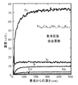
- FIG. 3 shows the concentration distribution in the depth direction from the surface of Fe, Si, O, Cu measured by GDOES from the surface on the free surface side toward the inside.
- the surface of the alloy was mostly Si and O, and oxides such as SiO 2 were mainly formed.
- the maximum value of the Cu concentration is about 6 atomic%, and this maximum value is larger than that before the heat treatment. Further, a region with a low Cu concentration exists at a deeper position, and the Cu concentration in this region was lowered. This minimum Cu concentration was 0.07 atomic%, which was less than 40% of the Cu concentration (1.1 atomic%) at a position 500 nm from the surface.
- the region where the Cu concentration was minimum was at a position of 36 nm from the surface.
- the O concentration at a position of 12 nm from the surface was 44.6 atomic%, the Fe concentration was 3.4 atomic%, and the O concentration was higher than the Fe concentration.
- a low Fe concentration at a position of 12 nm is preferable because the insulating property of the Si oxide layer formed on the surface becomes high, so that high-frequency magnetic characteristics can be improved and variation can be reduced.
- GDOES concentration dependency
- Example 3 In atomic%, Fe bal.
- the amorphous alloy had a halo pattern and an amorphous single phase.
- Cu of the segregated Cu portion was located at a position of 8 nm from the surface as in Example 1.
- the concentration was the maximum value.
- the maximum value of the Cu concentration is about 1.9 atomic%, and it was confirmed that a region with a low Cu concentration exists at a position 19.3 nm from the deeper surface.
- a ring-shaped sample was produced from this alloy ribbon by punching. Since the amorphous alloy ribbon of the present invention is excellent in toughness, it could be punched without cracking.
- Example 4 The amorphous alloy ribbon-shaped alloy sample obtained in Example 2 was heat-treated at 550 ° C. for 1 hour in an argon gas atmosphere with a dew point of ⁇ 70 ° C. to produce the nanocrystalline soft magnetic alloy core of the present invention.
- the ring samples were stacked and placed in a phenol resin core case, and the magnetic properties were measured.
- B 800 is 1.23 T
- H c is 0.4 A / m
- relative initial permeability ⁇ 1k at 1 kHz is 168000
- relative initial permeability ⁇ 100k at 100 kHz is 16500
- magnetic core loss P cm at 2 kHz is 2 0.0 W / kg.
- the surface of the alloy was mostly Si and O, and oxides such as SiO 2 were mainly formed.
- a Cu segregation portion was present at a position of 15.8 nm from the surface.
- the maximum value of the Cu concentration in the Cu segregation part was 5.0 atomic%, and the maximum value of the Cu concentration was larger than that before the heat treatment.
- a region with a low Cu concentration exists at a deeper position, and the Cu concentration in this region is lowered.
- the minimum Cu concentration was 0.0152 atomic%, which was less than 40% of the Cu concentration of 1.0 atomic% at a position 500 nm from the surface.
- the region where the Cu concentration is minimum was at a position of 36.7 nm from the surface.
- the O concentration at 12 nm from the surface was 42.1 atomic%, the Fe concentration was 5.6 atomic%, and the O concentration was higher than the Fe concentration.
- a transformer was produced by winding the produced magnetic core. It was confirmed that the loss was low and good characteristics were exhibited.
- Example 5 Amorphous alloy ribbons having the compositions shown in Table 1-1 and Table 1-2 were produced by a single roll method. It was produced in an atmosphere having an oxygen concentration of 20% by using a roll made of a Cu—Be based copper alloy.
- Table 1-1 corresponding to the example of the present invention, the temperature of the alloy ribbon at a position 250 mm from the pouring position (nozzle position) is measured with a radiation thermometer so that the temperature of the ribbon is 270 ° C. The water volume and temperature were adjusted.
- the amorphous alloy had a halo pattern and an amorphous single phase.
- the iron loss tended to be larger than 3.0 W / kg. It was confirmed that the iron loss at high frequency tends to be lower when the oxygen atom% concentration at a position of 12 nm from the surface is larger than the Fe atom% concentration.
- Example 6 A ring-shaped sample was punched out from an amorphous alloy ribbon having the alloy composition shown in Table 1-1 with a mold, and the toughness was examined by whether the sample was punched cleanly.
- Table 1-1 shows the segregated portion of Cu from the surface, the Cu concentration, and the Cu concentration of the matrix.
- An amorphous alloy ribbon having a Cu segregation portion with a Cu concentration of 4 atomic% or less was excellent in toughness and could be processed such as punching.
- Table 1-2 the amorphous alloy ribbon having a Cu segregation portion with a Cu concentration exceeding 4 atomic% cracked during punching.
- the present invention includes various transformers, various reactors / choke coils, noise countermeasure components, pulse power magnetic components used in laser power supplies and accelerators, communication pulse transformers, various motor cores, various generators, various magnetic sensors, antenna cores, Amorphous alloy ribbon with excellent workability for nanocrystalline soft magnetic alloys used in various current sensors, magnetic shields, nanocrystalline soft magnetic alloys exhibiting excellent magnetic properties, and the nanocrystalline soft magnetic alloys are used. Can be used as a magnetic core.
Landscapes
- Chemical & Material Sciences (AREA)
- Engineering & Computer Science (AREA)
- Physics & Mathematics (AREA)
- Materials Engineering (AREA)
- Power Engineering (AREA)
- Crystallography & Structural Chemistry (AREA)
- Mechanical Engineering (AREA)
- Organic Chemistry (AREA)
- Metallurgy (AREA)
- Dispersion Chemistry (AREA)
- Thermal Sciences (AREA)
- Nanotechnology (AREA)
- Electromagnetism (AREA)
- General Physics & Mathematics (AREA)
- Inorganic Chemistry (AREA)
- Condensed Matter Physics & Semiconductors (AREA)
- Composite Materials (AREA)
- Manufacturing & Machinery (AREA)
- Soft Magnetic Materials (AREA)
- Continuous Casting (AREA)
Abstract
Description
しかしながら、フェライト材料は、飽和磁束密度が低く、温度特性が悪いという問題があり、そのため、大容量インバータ・電源のコイル部品や配電用トランスなどハイパワーで使用される用途には、磁気的に飽和しやすく不向きである。ケイ素鋼板は、材料が安価で磁束密度は高いが、高周波の用途に対しては磁心損失が大きいという問題がある。
一方、非晶質合金は、通常、液相や気相から急冷し製造される。そのため、Fe基やCo基の非晶質合金は結晶粒が存在しないので本質的に結晶磁気異方性が存在せず、優れた軟磁気特性を示すことが知られている。このため、Fe基やCo基の非晶質合金は電力用変圧器鉄心、チョークコイル、磁気ヘッドや電流センサなどに使用されている。
代表的組成系としては、特許文献1や特許文献2に記載のFe-Cu-(Nb,Ti,Zr,Hf,Mo,W,Ta)-Si-B系合金やFe-Cu-(Nb,Ti,Zr,Hf,Mo,W,Ta)-B系合金等が知られている。これらのFe基ナノ結晶合金は、通常、液相や気相から急冷して非晶質合金とした後、これを熱処理により微結晶化することにより作製されている。液相から急冷する方法としては単ロール法、双ロール法、遠心急冷法、回転液中紡糸法、アトマイズ法やキャビテーション法等が知られている。また、気相から急冷する方法としては、スパッタ法、蒸着法、イオンプレーティング法等が知られている。Fe基ナノ結晶合金は、これらの方法により作製した非晶質合金を微結晶化したものであって、非晶質合金にみられるような熱的不安定性がほとんどなく、Fe系非晶質合金と同程度の高い飽和磁束密度と低磁歪を有する優れた軟磁気特性を示すことが知られている。更にナノ結晶合金は経時変化が小さく、温度特性にも優れていることが知られている。
また、特許文献4には、非晶質合金薄帯を加工するための技術として、合金組成にC,P,S元素などを添加して加工性をあげることが記載されている。
上述の通り、量産レベルで製造される非晶質合金薄帯は薄帯が脆化しやすいという課題がある。この原因のひとつとしては、ロール温度の上昇や鋳造雰囲気などの違いにより、薄帯表面の元素濃度分布が変化していることが考えられる。
非晶質合金薄帯が脆化すると、切断、打ち抜き、スリットなどの加工が難しくなり、磁心を製造する際にも問題となる。
また、特許文献4のようにN,C,P元素などを添加することは磁気特性を悪化させることになり、高磁気特性が求められるナノ結晶軟磁性合金の製造への適用が難しい。
したがって、加工性が良好なナノ結晶軟磁性合金用の非晶質合金薄帯の出現が強く望まれている。
また、上記の非晶質合金薄帯を熱処理してナノ結晶化させたナノ結晶軟磁性合金の軟磁気特性は、薄帯製造時の薄帯の熱履歴による影響を受けやすい。
特にナノ結晶材用の広幅の非晶質合金薄帯は、量産時のロール温度上昇により薄帯表面の変質などが起こりやすく、表面の元素濃度分布が量産時の製造条件の違いによって影響を受ける。熱処理を行いナノ結晶化した後の合金表面の元素濃度分布にも影響を与える。この元素分布は磁気特性に影響を与えるため、優れた軟磁気特性を得るにはナノ結晶化熱処理後の合金表面の元素分布を制御することが重要である。
Cuを含む本発明の非晶質合金薄帯は、薄帯製造の際、出湯位置からロール周方向で250mmの位置での合金薄帯の温度が200℃以上400℃以下の条件で製造する。250mmの位置の合金薄帯温度が200℃未満ではCu偏析部とCu濃度の少ない領域が十分形成されないため、熱処理後表面に粗大な結晶が形成しやすくなる。400℃を超えると、熱処理前の段階で非晶質合金薄帯が脆化しやすくなるため、好ましくない。
また、本発明非晶質合金薄帯製造の際に、薄帯がロールに密着している付近のガス中に5%以上の酸素が含まれる雰囲気の下で製造することによりCu偏析部より表面側の浅い位置のSiの濃度ピークを制御でき、薄帯表面におけるSiO2系の酸化皮膜の厚さが制御できる。これにより絶縁性が向上し、積層磁心や巻磁心とした場合の高周波磁気特性が改善される。本発明ナノ結晶軟磁性合金において合金表面から12nmの位置の酸素濃度(原子%)がFe濃度(原子%)よりも高い場合、表面の絶縁がよりやぶれにくく、巻磁心や積層磁心として使用した場合に、高周波特性の劣化やばらつきを抑制できる。
この際、合金の表面から12nmの位置の酸素濃度がFe濃度よりも高いことが好ましい。
このCu元素の偏析と併せて合金の表面から12nmの位置の酸素濃度がFe濃度よりも高くなるように制御することが好ましい。Cu元素の偏析と合金の表面から12nmの位置の酸素濃度がFe濃度よりも高くなる元素分布があることで、鉄損が改善される相乗効果が得られる。
また、前記Cu偏析部のCu濃度の最大値が母相のCu濃度の2倍以上であることが好ましい。
MはTi、V、Zr、Nb、Mo、Hf、Ta、Wから選ばれる元素を少なくとも1種含むものであり、非晶質化を助ける効果と熱処理により結晶化する際に結晶粒を微細化する効果を有する。また、Ti、Nb、Taなどの元素は耐蝕性を向上する効果も有している。
M量aは10原子%以下である必要がある。これはM量aが10原子%を超えると磁束密度の著しい低下を招くためである。但し、M量aが0原子%でも非晶質合金薄帯は得られ、Cu偏析部のCu濃度の最大値を下げればM元素を含むものと同様に加工性は向上する。Siは非晶質化を助ける効果があり、ナノ結晶軟磁性材料においては軟磁気特性を向上させたり磁歪を低減させたりする効果を有する。また、表面に酸化物の形で偏析することにより、耐環境性を改善したり、磁心に使用する場合の層間絶縁性を向上したりする効果がある。
Si量bは20原子%以下である必要がある。これはSi量が20原子%を超えると飽和磁束密度の著しい低下を招き好ましくないためである。特に好ましいSi量bの範囲は8≦b≦17であり、優れた軟磁気特性が得られる。但し、Si量bが0原子%でも非晶質合金薄帯は得られ、Cu偏析部のCu濃度の最大値を下げればM元素を含むものと同様に加工性は向上する。
Bは非晶質形成能を高める元素であり、B量cは4原子%以上20原子%以下である必要がある。これは、B量cが4原子%未満では非晶質形成が困難となって好ましくなく、20原子%を超えると飽和磁束密度の著しい低下を招くためである。特に好ましいB量cの範囲は5≦c≦10であり、ナノ結晶化後に特に優れた軟磁気特性が得られ、磁歪も比較的低くすることができる。
Cuはナノ結晶化の際に結晶粒を微細化・結晶粒組織を均一化する効果を有する。Cuが0.1原子%未満であるとこの効果が不十分である。一方、Cu量dは3原子%以下である必要がある。これは、Cu量dが3原子%を超えると連続的な非晶質合金薄帯製造が困難となるためである。特に好ましいCu量dの範囲は0.4≦d≦2、さらには0.5≦d≦1.5であり、この範囲で非晶質合金薄帯製造が容易でかつナノ結晶化後のナノ結晶合金において特に優れた軟磁気特性を実現できる。
M量a、Si量b、B量cの総和a+b+cは9≦a+b+c≦35である必要がある。これは、M量a、Si量b、B量cの総和a+b+cが9原子%未満では非晶質化が困難であり、35原子%を超えると飽和磁束密度の著しい低下を招くためである。
Mの50%以下をCr、Mn、Zn、As、Se、Sb、Sn、In、Cd、Ag、Bi、Mg、Sc、Re、Au、白金族元素、Y、希土類元素から選ばれた少なくとも1種の元素で置換することができる。
その後、結晶化温度以上の温度領域まで加熱し熱処理を施し、結晶粒径50nm以下の体心立方構造の結晶粒が非晶質母相中に分散した組織とする。ナノ結晶粒相が体積分率で50%以上を占めることにより、軟磁性を更に改善させることや磁歪の低減が図れる。
結晶粒の体積比は、線分法により求められる。すなわち結晶粒の体積比は、顕微鏡組織写真中に任意の直線を想定しそのテストラインの長さをLt、結晶相により占められる線の長さLcを測定し、結晶粒により占められる線の長さの割合LL=Lc/Ltを求めることにより得られる。熱処理後の合金中に存在する結晶粒の結晶粒径は、50nm以下が望ましい。これは、結晶粒径が50nmを超えると軟磁気特性の著しい劣化が起こり好ましくないためである。特に好ましい結晶粒径は5nm~20nmであり、特に優れた軟磁性が得られる。
アモルファス母相中にナノスケールのbcc結晶粒が分散した組織の合金は、抵抗率が高く、結晶粒成長が抑制され、高周波の磁気特性が改善されるためより好ましい結果が得られる。
本発明のナノ結晶軟磁性合金においては、一部に化合物相を含んでもよいが、化合物相が存在しない場合には、より低い保磁力、低い磁心損失を示すことができる。
また、本発明のナノ結晶軟磁性合金は、Cu元素の偏析や酸素の偏析を制御することで、特性のばらつきが少ない優れた軟磁気特性を示すものが得られる。
原子%でFebal.Cu0.98Nb3.1Si13.4B9.3の合金組成で幅50mm厚さ19μmの非晶質合金薄帯を作製した。Cu-Be系の銅合金製のロールを用いて、酸素濃度20%の雰囲気中で作製した。出湯位置(ノズル位置)から250mmの位置での合金薄帯の温度を放射温度計により測定しながら、270℃の温度になるよう冷却水量と水温を調整して作製した。作製した非晶質合金薄帯のX線回折を自由面側とロール面側で行った結果、非晶質合金特有のハローパターンであり非晶質単相であることが確認された。また、作製した非晶質合金を切断し加工性を調査した結果、割れが発生せず、加工性に優れていることが確認された。
作製した合金薄帯の自由面(自由凝固した面)の表面から内部に向かって元素の濃度分布をグロー放電発光分光分析[GDOES(Glow Discharge Optical Emission Spectroscopy)]により測定した。深さ500nmまでFe,Si,B,Nb,Cuを分析して得られた結果を図1に示す。また図2に、同じ試料の表面から100nmの範囲のFe,Si,O,Cuの濃度分布を拡大して示す。合金の表面はSiとOが多く、SiO2などの酸化物が主として形成されていた。表面から7.4nmの位置でCu偏析部のCu濃度が最大値となっているところのCu濃度は1.7原子%程度あり、更にそれより深い表面から18.2nmの位置にCu濃度の低い領域が存在していた。この領域のCu濃度は表面から500nmの位置のCu濃度よりも低かった。ロール面側も同様のGDOESによる分析を行った結果、類似した濃度依存性を示すことが確認された。
次に、この合金薄帯を外径38mm、内径30mmに巻き回して巻磁心を作製した。この巻磁心の一部を切断加工したところ、割れも発生せず、綺麗な切断面を持つ巻磁心が得られた。露点が-61℃の窒素ガス雰囲気中で、550℃で1時間保持して、熱処理を行った。この巻磁心の磁気特性は、800A/mにおける磁束密度B800が1.24T、保磁力Hcが0.35A/m、最大比透磁率μmが1100000、1kHzにおける比初透磁率が129000であった。熱処理後の合金のX線回折を行った結果、体心立方(bcc)構造のFe-Si結晶相が形成していることが確認された。TEMによる組織観察の結果、合金表面に大きな結晶は存在せず、粒径約12nmのbccFe-Si結晶粒がアモルファス母相中に形成していることが確認された。次に、熱処理後の合金薄帯について同様にGDOESによる分析を行った。合金の表面にはSiとOが多く、SiO2などの酸化物が主として形成されていた。表面から15.6nmの位置にCu偏析部が存在していた。Cu偏析部は6原子%程度あり、熱処理前よりもCu濃度の最大値は大きくなった。本発明の非晶質合金薄帯は、靭性に優れており、熱処理によりナノ結晶化を行った後のナノ結晶合金の磁気特性も優れていた。
また、非晶質合金薄帯を酸素濃度20%の雰囲気中でCu-Be系の銅合金製のロールを用いて、出湯位置(ノズル位置)から250mmの位置での合金薄帯の温度を放射温度計により測定しながら、420℃の温度になるよう冷却水量と水温を調整して非晶質合金薄帯を作製した。作製した合金薄帯を切断したところ、上記と同様に割れが発生し加工性に劣ることが確認された。作製した合金薄帯の自由面(自由凝固した面)の表面から内部に向かって元素の濃度分布をGDOESにより測定したところ、Cu偏析部の濃度の最高値は4原子%を超えた値であることが確認された。
実施例1で得た非晶質合金薄帯を外径38mm、内径30mmに巻き回して巻磁心を作製し、露点が-61℃の窒素ガス雰囲気中で、550℃で1時間保持して、熱処理を行い、これにより本発明のナノ結晶合金からなる巻磁心を得た。この巻磁心の磁気特性は800A/mにおける磁束密度B800が1.24T、保磁力Hcが0.35A/m、最大比透磁率μmが1100000、1kHzにおける比初透磁率が129000である。
熱処理後の合金のX線回折を行った結果、体心立方(bcc)構造のFe-Si結晶相が形成していることが確認された。TEMによる組織観察の結果、合金表面に大きな結晶は存在せず、粒径約12nmのbccFe-Si結晶粒がアモルファス母相中に形成していることが確認された。
また、熱処理後の合金薄帯について同様にGDOESによる分析を行った。自由面側の表面から内部に向かってGDOESにより測定したFe,Si,O,Cuの表面から深さ方向の濃度分布を図3に示す。また、図4に、同じ試料の表面から100nmの範囲のFe,Si,O,Cuの濃度分布を拡大して示す。合金の表面はSiとOが多く、SiO2などの酸化物が主として形成されていた。表面から15.6nmの位置にCu偏析部のCu濃度が最大となる部分が存在していた。Cu濃度の最大値は6原子%程度あり、熱処理前よりもこの最大値は大きくなっていた。更にそれより深い位置にCu濃度の低い領域が存在し、この領域のCu濃度は低下していた。この最小のCu濃度は0.07原子%であり、表面から500nmの位置のCu濃度(1.1原子%)の40%未満であった。このCu濃度が最小となる領域は、表面から36nmの位置であった。表面から12nmの位置のO濃度は44.6原子%、Fe濃度は3.4原子%であり、O濃度はFe濃度より高かった。12nmの位置のFe濃度が低いと表面に形成されるSi酸化物層の絶縁性が高くなるため、高周波磁気特性が向上したり、ばらつきを低減できたりして、好ましい。また、ロール面側も同様のGDOESによる分析を行った結果、類似した濃度依存性を示すことが確認された。
原子%でFebal.Cu0.95Nb3.0Si15.5B6.8の合金組成であって、幅25mm厚さ18μmの非晶質合金薄帯を作製した。Cu-Be系の銅合金製のロールを用いて、酸素濃度21%の雰囲気中で作製した。出湯位置(ノズル位置)から250mmの位置での合金薄帯の温度を放射温度計により測定しながら、250℃の温度になるよう冷却水量と水温を調整して作製した。作製した非晶質合金薄帯のX線回折を自由面側とロール面側で行った結果、非晶質合金特有のハローパターンであり非晶質単相であることが確認された。作製した合金薄帯のロール面(ロールと接触した面)の表面から内部に向かって元素の濃度分布をGDOESにより測定した結果、実施例1と同様に表面から8nmの位置でCu偏析部のCu濃度が最大値になっていた。Cu濃度の最大値は1.9原子%程度あり、更にそれより深い表面から19.3nmの位置にCu濃度の低い領域が存在することが確認された。この合金薄帯からリング状の試料を打ち抜き加工により作製した。本発明の非晶質合金薄帯は靭性に優れているため割れなどは発生せず打ち抜くことが可能であった。
実施例2で得た非晶質合金薄帯のリング状の合金試料を、露点が-70℃のアルゴンガス雰囲気中で550℃1時間の熱処理を行い、本発明ナノ結晶軟磁性合金磁心を作製し、このリング試料を重ねてフェノール樹脂製のコアケースに入れ、磁気特性を測定した。B800は1.23T、Hcは0.4A/m、1kHzにおける比初透磁率μ1kは168000、100kHzにおける比初透磁率μ100kは16500、20kHz,0.2Tにおける磁心損失Pcmは2.0W/kgであった。熱処理後の合金薄帯のX線回折およびTEM観察を行った結果、組織の73%が粒径約14nmのbccFe-Si結晶粒からなることが確認された。規則相による回折ピークも確認されたことから規則相が存在していることも確認された。次に作製した磁心に巻線をしてトランスを作製した。損失が低く良好な特性を示すことが確認された。
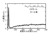
次にロール面(ロールと接触した面)の表面から内部に向かってCuの濃度分布を深さ500nmまでGDOESにより測定した。図5にCuの濃度分布を示す。また図6に同じ試料の表面から100nmの範囲でのCuの濃度分布を拡大して示す。合金の表面はSiとOが多く、SiO2などの酸化物が主として形成されていた。表面から15.8nmの位置にCu偏析部が存在していた。このときのCu偏析部のCu濃度の最大値は5.0原子%であり、熱処理前よりもCu濃度の最大値は大きかった。更にそれより深い位置にCu濃度の低い領域が存在し、この領域のCu濃度は低下している。最小のCu濃度は0.0152原子%であり、表面から500nmの位置でのCu濃度1.0原子%の40%未満であった。このCu濃度が最小となる領域は、表面から36.7nmの位置であった。表面から12nmの位置のO濃度は42.1原子%、Fe濃度は5.6原子%であり、O濃度はFe濃度より高かった。
次に作製した磁心に巻線してトランスを作製した。損失が低く良好な特性を示すことが確認された。
表1-1及び表1-2に示す組成の非晶質合金薄帯を単ロール法により作製した。Cu-Be系の銅合金製のロールを用いて、酸素濃度20%の雰囲気中で作製した。
本発明例に相当する表1-1では、出湯位置(ノズル位置)から250mmの位置での合金薄帯の温度を放射温度計により測定しながら、その薄帯の温度が270℃になるよう冷却水量と水温を調整し作製した。作製した非晶質合金薄帯のX線回折を自由面側とロール面側で行った結果、非晶質合金特有のハローパターンであり非晶質単相であることが確認された。また、作製した非晶質合金を切断し加工性を調査した結果、本発明例に相当する表1-1では、割れが発生せず、加工性に優れていることが確認された。
次に、表1-1の非晶質合金薄帯を巻き回して巻磁心とし、露点が-61℃の窒素ガス雰囲気中で熱処理を行い、本発明のナノ結晶軟磁性合金の磁心を作製した。この磁心の20kHz,0.2Tにおける鉄損Pcmを測定した。また、熱処理後の合金薄帯のX線回折を行った結果、体心立方構造(bcc)構造のFe-Si結晶相が形成していることが確認された。透過電子顕微鏡(TEM)とX線回折からシェラーの式により平均粒径を見積もった結果、粒径粒径50nmのbccFe-Si結晶粒が形成し、その体積分率は50%以上であることが確認された。次に、熱処理後の合金薄帯について同様にGDOESによる分析を行った。表面からのCu偏析部のCu濃度が最大となる位置とCu濃度、Cu濃度の低い領域の最小値と母相のCu濃度、および表面から12nmの位置の酸素原子%濃度CC(O)とFe原子%濃度CC(Fe)の比CC(O)/CC(Fe)、鉄損Pcmの測定結果を表2-1に示す。
また比較のために、真空度1.3×10⁻³Paの高真空度の雰囲気中で熱処理した場合の測定結果を表2-2に示す。
その結果、本発明のナノ結晶軟磁性合金磁心は優れた磁気特性を示すことが確認された。これに対して、高真空度の雰囲気で熱処理した試料では鉄損が3.0W/kgより大きくなる傾向が見られた。表面から12nmの位置の酸素原子%濃度がFe原子%濃度よりも大きい場合の方が高周波における鉄損が低くなる傾向があることが確認された。

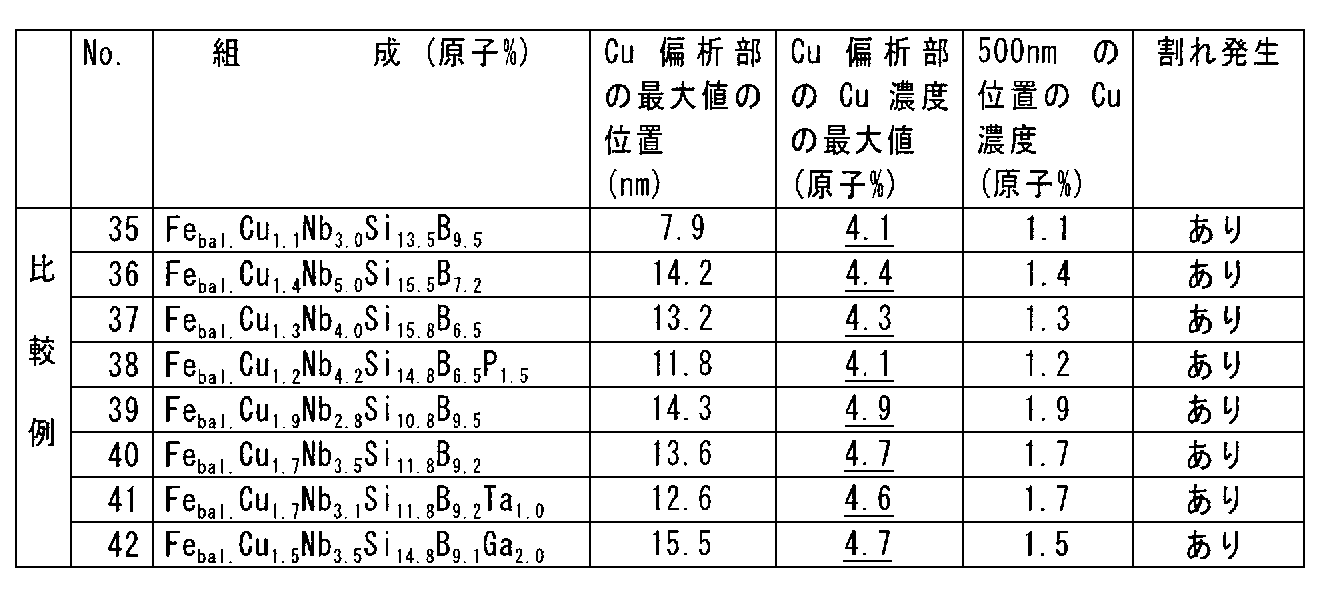
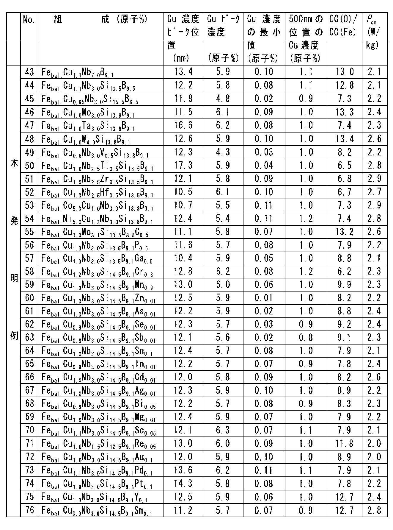

表1-1に示す合金組成の非晶質合金薄帯から金型によりリング状の試料を打ち抜き、きれいに試料が打ち抜けるか否かによって靭性を調査した。表面からのCu偏析部とCu濃度と母相のCu濃度を表1-1に併記する。Cu偏析部のCu濃度が4原子%以下の非晶質合金薄帯は、靭性に優れており、打ち抜きなどの加工が可能であった。これに対して、表1-2に示される通り、Cu偏析部のCu濃度が4原子%を超える非晶質合金薄帯は打ち抜きの際に割れが発生した。
Claims (10)
- 合金組成がFe100-a-b-c-dMaSibBcCud(原子%)で表され、0≦a≦10、0≦b≦20、4≦c≦20、0.1≦d≦3、9≦a+b+c≦35および不可避不純物からなる非晶質合金薄帯であって、ここでMはTi、V、Zr、Nb、Mo、Hf、Ta、Wから選ばれる元素を少なくとも1種含むものであり、該非晶質合金薄帯の表面側に最表面部よりも高い濃度でCuが偏析しているCu偏析部が存在し、そのCu偏析部でのCu濃度の最大値が4原子%以下である、上記非晶質合金薄帯。
- 前記Cu偏析部でのCu濃度の最大値が前記薄帯表面から500nmの位置のCu濃度よりも高く、前記Cu偏析部より表面側の位置にSiの偏析部が存在する、請求項1に記載の非晶質合金薄帯。
- 熱処理を施してナノ結晶化させた、請求項1又は2に記載の非晶質合金薄帯を含んでなる、ナノ結晶軟磁性合金。
- 請求項3に記載のナノ結晶軟磁性合金を含んでなる、磁心。
- Cu元素を含み平均粒径が50nm以下の結晶粒が少なくとも一部に存在するナノ結晶軟磁性合金であって、該合金の表面から2nmよりも深い位置にCu元素が偏析するCu偏析部が存在し、該Cu偏析部のCu濃度の最大値が6原子%以下である、上記ナノ結晶軟磁性合金。
- 前記合金の表面から12nmの位置の酸素濃度がFe濃度よりも高い、請求項6に記載のナノ結晶軟磁性合金。
- 前記Cu偏析部より深い位置に、母相よりもCu濃度が低い領域が存在し、この位置でのCu濃度の最小値が母相のCu濃度の40%未満である、請求項5に記載のナノ結晶軟磁性合金。
- 前記Cu偏析部のCu濃度の最大値が母相のCu濃度の2倍以上である、請求項5乃至請求項7に記載のナノ結晶軟磁性合金。
- 合金組成がFe100-a-b-c-dMaSibBcCud(原子%)で表され、0≦a≦10、0≦b≦20、4≦c≦20、0<d≦3、9≦a+b+c≦35および不可避不純物からなる非晶質合金であり、ここでMはTi、V、Zr、Nb、Mo、Hf、Ta、Wから選ばれる元素を少なくとも1種含むものである、請求項5乃至8に記載のナノ結晶軟磁性合金。
- 請求項5乃至9に記載のナノ結晶軟磁性合金を含んでなる、磁心。
Priority Applications (5)
| Application Number | Priority Date | Filing Date | Title |
|---|---|---|---|
| ES09727120.9T ES2633946T3 (es) | 2008-03-31 | 2009-03-30 | Tira delgada de aleación amorfa, aleación magnética blanda de nanocristal y núcleo magnético |
| EP09727120.9A EP2261385B1 (en) | 2008-03-31 | 2009-03-30 | Thin strip of amorphous alloy, nanocrystal soft magnetic alloy, and magnetic core |
| CN200980100276.4A CN101796207B (zh) | 2008-03-31 | 2009-03-30 | 非晶态合金薄带,纳米晶态软磁性合金和磁芯 |
| US12/675,286 US8414712B2 (en) | 2008-03-31 | 2009-03-30 | Thin strip of amorphous alloy, nanocrystal soft magnetic alloy, and magnetic core |
| KR1020107004501A KR101257248B1 (ko) | 2008-03-31 | 2009-03-30 | 비정질 합금 박대, 나노 결정 연자성 합금, 및 자심 |
Applications Claiming Priority (2)
| Application Number | Priority Date | Filing Date | Title |
|---|---|---|---|
| JP2008092784 | 2008-03-31 | ||
| JP2008-092784 | 2008-03-31 |
Publications (1)
| Publication Number | Publication Date |
|---|---|
| WO2009123100A1 true WO2009123100A1 (ja) | 2009-10-08 |
Family
ID=41135474
Family Applications (1)
| Application Number | Title | Priority Date | Filing Date |
|---|---|---|---|
| PCT/JP2009/056476 Ceased WO2009123100A1 (ja) | 2008-03-31 | 2009-03-30 | 非晶質合金薄帯、ナノ結晶軟磁性合金、並びに磁心 |
Country Status (7)
| Country | Link |
|---|---|
| US (1) | US8414712B2 (ja) |
| EP (1) | EP2261385B1 (ja) |
| JP (1) | JP5339192B2 (ja) |
| KR (1) | KR101257248B1 (ja) |
| CN (1) | CN101796207B (ja) |
| ES (1) | ES2633946T3 (ja) |
| WO (1) | WO2009123100A1 (ja) |
Cited By (7)
| Publication number | Priority date | Publication date | Assignee | Title |
|---|---|---|---|---|
| EP2375784A3 (de) * | 2010-03-26 | 2013-05-01 | Siemens Medical Instruments Pte. Ltd. | Hörgerät mit amorpher Lautsprecherabschirmung |
| US20160196908A1 (en) * | 2015-01-07 | 2016-07-07 | Metglas, Inc. | Magnetic core based on a nanocrystalline magnetic alloy |
| CN106756596A (zh) * | 2016-12-28 | 2017-05-31 | 长沙伟泰塑胶科技有限公司 | 一种合金材料及其制备方法 |
| CN113451031A (zh) * | 2020-03-27 | 2021-09-28 | 日立金属株式会社 | 卷绕磁芯的制造方法、及卷绕磁芯 |
| US11230754B2 (en) | 2015-01-07 | 2022-01-25 | Metglas, Inc. | Nanocrystalline magnetic alloy and method of heat-treatment thereof |
| CN115003837A (zh) * | 2020-01-23 | 2022-09-02 | 株式会社村田制作所 | 合金和成型体 |
| CN116543996A (zh) * | 2023-04-23 | 2023-08-04 | 北京航空航天大学杭州创新研究院 | 一种高分子接枝的非晶-纳米晶软磁合金复合材料及其制备方法与应用 |
Families Citing this family (45)
| Publication number | Priority date | Publication date | Assignee | Title |
|---|---|---|---|---|
| JP5429613B2 (ja) * | 2009-03-26 | 2014-02-26 | 日立金属株式会社 | ナノ結晶軟磁性合金ならびに磁心 |
| JP5327075B2 (ja) * | 2010-01-20 | 2013-10-30 | 日立金属株式会社 | 軟磁性合金薄帯及びその製造方法、並びに軟磁性合金薄帯を有する磁性部品 |
| JP5645108B2 (ja) * | 2010-07-14 | 2014-12-24 | 日立金属株式会社 | 非晶質合金薄帯および非晶質合金薄帯を有する磁性部品 |
| EP2416329B1 (de) * | 2010-08-06 | 2016-04-06 | Vaccumschmelze Gmbh & Co. KG | Magnetkern für Niederfrequenzanwendungen und Verfahren zur Herstellung eines Magnetkerns für Niederfrequenzanwendungen |
| US20140191832A1 (en) * | 2011-10-03 | 2014-07-10 | Hitachi Metals, Ltd. | Primary ultrafine-crystalline alloy ribbon and its cutting method, and nano-crystalline, soft magnetic alloy ribbon and magnetic device using it |
| WO2013137857A2 (en) | 2012-03-12 | 2013-09-19 | The Massachusetts Institute Of Technology | Stable binary nanocrystalline alloys and methods of identifying same |
| CN102732811A (zh) * | 2012-06-21 | 2012-10-17 | 四川大学苏州研究院 | 高饱和磁化强度铁基非晶纳米晶软磁合金及其制备方法 |
| CN102723158B (zh) * | 2012-07-06 | 2015-12-02 | 白皞 | 含稀土的高磁导率Ni-Fe软磁合金及其制备方法和用途 |
| CN102909326B (zh) * | 2012-10-24 | 2014-08-13 | 安泰科技股份有限公司 | 具有成分梯度的非晶合金带材及其制造方法 |
| KR101399429B1 (ko) * | 2012-11-08 | 2014-05-27 | 이상민 | 연자성체 스트립 가공장치 |
| JP6041207B2 (ja) * | 2012-12-27 | 2016-12-07 | 日立金属株式会社 | ナノ結晶軟磁性合金及びこれを用いた磁性部品 |
| WO2014152838A1 (en) | 2013-03-14 | 2014-09-25 | Massachusetts Institute Of Technology | Sintered nanocrystalline alloys |
| CN104934179B (zh) * | 2014-05-27 | 2017-06-13 | 安泰科技股份有限公司 | 强非晶形成能力的铁基纳米晶软磁合金及其制备方法 |
| KR102203689B1 (ko) | 2014-07-29 | 2021-01-15 | 엘지이노텍 주식회사 | 연자성 합금, 이를 포함하는 무선 전력 송신 장치 및 무선 전력 수신 장치 |
| CN107109562B (zh) * | 2014-12-22 | 2019-07-23 | 日立金属株式会社 | Fe基软磁性合金薄带以及使用其的磁心 |
| JP2016197510A (ja) * | 2015-04-02 | 2016-11-24 | 日立金属株式会社 | 磁気シールド素線及びその製造方法並びにそれを用いた磁気シールド編組スリーブ及び磁気シールドケーブル |
| JP6427677B2 (ja) * | 2015-07-31 | 2018-11-21 | 株式会社村田製作所 | 軟磁性材料およびその製造方法 |
| WO2017105570A2 (en) | 2015-09-17 | 2017-06-22 | Massachusetts Institute Of Technology | Nanocrystalline alloy penetrators |
| JP6904034B2 (ja) * | 2017-04-17 | 2021-07-14 | セイコーエプソン株式会社 | 軟磁性粉末、圧粉磁心、磁性素子および電子機器 |
| JP2020518726A (ja) * | 2017-05-04 | 2020-06-25 | マサチューセッツ インスティテュート オブ テクノロジー | 鉄含有合金、ならびに関連する系および方法 |
| CN107245673B (zh) * | 2017-06-15 | 2018-12-07 | 河北工业大学 | 铁基非晶纳米晶薄带磁体及其制备方法和应用方法 |
| US11037711B2 (en) * | 2017-07-05 | 2021-06-15 | Panasonic Intellectual Property Management Co., Ltd. | Soft magnetic alloy powder, method for producing same, and dust core using soft magnetic alloy powder |
| CN107464649B (zh) * | 2017-08-03 | 2020-03-17 | 江苏奥玛德新材料科技有限公司 | 一种具有线性磁滞回线的磁芯 |
| CN111033648B (zh) * | 2017-08-18 | 2022-04-19 | 3M创新有限公司 | 磁膜 |
| KR102470926B1 (ko) * | 2017-08-18 | 2022-11-25 | 쓰리엠 이노베이티브 프로퍼티즈 컴파니 | 자성 필름 |
| CN108777205A (zh) * | 2018-04-25 | 2018-11-09 | 天长市中德电子有限公司 | 一种铁硅铝复合磁粉芯及其制备方法 |
| JP7099035B2 (ja) | 2018-04-27 | 2022-07-12 | セイコーエプソン株式会社 | 軟磁性粉末、圧粉磁心、磁性素子および電子機器 |
| JP7318219B2 (ja) * | 2019-01-30 | 2023-08-01 | セイコーエプソン株式会社 | 軟磁性粉末、圧粉磁心、磁性素子および電子機器 |
| WO2020179399A1 (ja) * | 2019-03-01 | 2020-09-10 | 日立金属株式会社 | アモルファス金属薄片、積層コア、および、アモルファス金属薄帯の打抜き加工方法 |
| WO2020215076A1 (en) * | 2019-04-18 | 2020-10-22 | Carnegie Mellon University | Transformer and method of engineering a transformer to incorporate a leakage inductance |
| CN110257698B (zh) * | 2019-05-09 | 2022-12-13 | 佛山市华信微晶金属有限公司 | 一种适合汽车充电桩磁芯的纳米晶带材及其制备方法 |
| RU2706081C1 (ru) * | 2019-07-12 | 2019-11-13 | Федеральное Государственное Унитарное Предприятие "Центральный научно-исследовательский институт черной металлургии им. И.П. Бардина (ФГУП "ЦНИИчермет им. И.П. Бардина") | Способ изготовления ленты из магнитно-мягкого аморфного сплава с увеличенной магнитной индукцией на основе системы Fe-Ni-Si-B |
| CN111850431B (zh) | 2019-09-23 | 2022-02-22 | 宁波中科毕普拉斯新材料科技有限公司 | 一种含亚纳米尺度有序团簇的铁基非晶合金、制备方法及其纳米晶合金衍生物 |
| JP7761987B2 (ja) * | 2019-11-22 | 2025-10-29 | Tdk株式会社 | 軟磁性合金薄帯および磁性部品 |
| JP2021080546A (ja) | 2019-11-22 | 2021-05-27 | Tdk株式会社 | 軟磁性合金薄帯および磁性部品 |
| EP3842555B1 (en) * | 2019-12-26 | 2024-02-14 | Proterial, Ltd. | Soft magnetic alloy and magnetic core |
| JP7400578B2 (ja) * | 2020-03-24 | 2023-12-19 | Tdk株式会社 | 合金薄帯および磁性コア |
| JP2021193205A (ja) * | 2020-06-08 | 2021-12-23 | 株式会社Bmg | Fe系ナノ結晶軟磁性合金 |
| JP7452335B2 (ja) * | 2020-08-31 | 2024-03-19 | 日本ケミコン株式会社 | Fe基ナノ結晶合金磁心の製造方法 |
| JP7574681B2 (ja) * | 2021-02-08 | 2024-10-29 | セイコーエプソン株式会社 | 軟磁性粉末、圧粉磁心、磁性素子および電子機器 |
| CN117980522A (zh) * | 2021-09-17 | 2024-05-03 | 阿莫绿色技术有限公司 | 铁基软磁合金及其制备方法 |
| JP7815764B2 (ja) * | 2022-01-05 | 2026-02-18 | セイコーエプソン株式会社 | 軟磁性粉末、圧粉磁心、磁性素子および電子機器 |
| JP7819508B2 (ja) * | 2022-01-27 | 2026-02-25 | セイコーエプソン株式会社 | 軟磁性粉末、圧粉磁心、磁性素子および電子機器 |
| JP2025002682A (ja) * | 2023-06-23 | 2025-01-09 | 株式会社トーキン | 磁性部品及び磁性粉末 |
| DE102024200486A1 (de) * | 2024-01-19 | 2025-07-24 | Fraunhofer-Gesellschaft zur Förderung der angewandten Forschung eingetragener Verein | Verfahren zur Herstellung zum Herstellen eines weichmagnetischen Kerns |
Citations (6)
| Publication number | Priority date | Publication date | Assignee | Title |
|---|---|---|---|---|
| JPH01242755A (ja) | 1988-03-23 | 1989-09-27 | Hitachi Metals Ltd | Fe基磁性合金 |
| JPH044393B2 (ja) | 1986-12-15 | 1992-01-28 | ||
| JP2001001113A (ja) * | 1999-04-15 | 2001-01-09 | Hitachi Metals Ltd | 合金薄帯並びにそれを用いた部材、及びその製造方法 |
| JP2002075718A (ja) | 2000-08-28 | 2002-03-15 | Hitachi Metals Ltd | 軟磁性薄板、軟磁性薄板を用いた磁心、カレントトランス、および磁心の製造方法 |
| JP2006316348A (ja) | 2005-04-15 | 2006-11-24 | Nippon Steel Corp | Fe系非晶質合金薄帯 |
| JP2007182594A (ja) * | 2006-01-04 | 2007-07-19 | Hitachi Metals Ltd | 非晶質合金薄帯、ナノ結晶軟磁性合金ならびにナノ結晶軟磁性合金からなる磁心 |
Family Cites Families (4)
| Publication number | Priority date | Publication date | Assignee | Title |
|---|---|---|---|---|
| EP1045402B1 (en) * | 1999-04-15 | 2011-08-31 | Hitachi Metals, Ltd. | Soft magnetic alloy strip, manufacturing method and use thereof |
| CN1306057C (zh) * | 2004-12-24 | 2007-03-21 | 安泰科技股份有限公司 | 含有微量稀土元素的铁基纳米晶合金 |
| CN100445410C (zh) * | 2005-09-27 | 2008-12-24 | 同济大学 | 一种纳米晶软磁合金材料及其制备方法 |
| CN100457955C (zh) * | 2007-04-16 | 2009-02-04 | 安泰科技股份有限公司 | 铁基大块非晶合金材料 |
-
2009
- 2009-03-24 JP JP2009071652A patent/JP5339192B2/ja active Active
- 2009-03-30 ES ES09727120.9T patent/ES2633946T3/es active Active
- 2009-03-30 KR KR1020107004501A patent/KR101257248B1/ko active Active
- 2009-03-30 EP EP09727120.9A patent/EP2261385B1/en active Active
- 2009-03-30 CN CN200980100276.4A patent/CN101796207B/zh active Active
- 2009-03-30 WO PCT/JP2009/056476 patent/WO2009123100A1/ja not_active Ceased
- 2009-03-30 US US12/675,286 patent/US8414712B2/en active Active
Patent Citations (6)
| Publication number | Priority date | Publication date | Assignee | Title |
|---|---|---|---|---|
| JPH044393B2 (ja) | 1986-12-15 | 1992-01-28 | ||
| JPH01242755A (ja) | 1988-03-23 | 1989-09-27 | Hitachi Metals Ltd | Fe基磁性合金 |
| JP2001001113A (ja) * | 1999-04-15 | 2001-01-09 | Hitachi Metals Ltd | 合金薄帯並びにそれを用いた部材、及びその製造方法 |
| JP2002075718A (ja) | 2000-08-28 | 2002-03-15 | Hitachi Metals Ltd | 軟磁性薄板、軟磁性薄板を用いた磁心、カレントトランス、および磁心の製造方法 |
| JP2006316348A (ja) | 2005-04-15 | 2006-11-24 | Nippon Steel Corp | Fe系非晶質合金薄帯 |
| JP2007182594A (ja) * | 2006-01-04 | 2007-07-19 | Hitachi Metals Ltd | 非晶質合金薄帯、ナノ結晶軟磁性合金ならびにナノ結晶軟磁性合金からなる磁心 |
Non-Patent Citations (1)
| Title |
|---|
| See also references of EP2261385A4 * |
Cited By (9)
| Publication number | Priority date | Publication date | Assignee | Title |
|---|---|---|---|---|
| EP2375784A3 (de) * | 2010-03-26 | 2013-05-01 | Siemens Medical Instruments Pte. Ltd. | Hörgerät mit amorpher Lautsprecherabschirmung |
| US8649542B2 (en) | 2010-03-26 | 2014-02-11 | Siemens Medical Instruments Pte. Ltd. | Hearing aid with amorphous loudspeaker shielding |
| US20160196908A1 (en) * | 2015-01-07 | 2016-07-07 | Metglas, Inc. | Magnetic core based on a nanocrystalline magnetic alloy |
| US11230754B2 (en) | 2015-01-07 | 2022-01-25 | Metglas, Inc. | Nanocrystalline magnetic alloy and method of heat-treatment thereof |
| US11264156B2 (en) * | 2015-01-07 | 2022-03-01 | Metglas, Inc. | Magnetic core based on a nanocrystalline magnetic alloy |
| CN106756596A (zh) * | 2016-12-28 | 2017-05-31 | 长沙伟泰塑胶科技有限公司 | 一种合金材料及其制备方法 |
| CN115003837A (zh) * | 2020-01-23 | 2022-09-02 | 株式会社村田制作所 | 合金和成型体 |
| CN113451031A (zh) * | 2020-03-27 | 2021-09-28 | 日立金属株式会社 | 卷绕磁芯的制造方法、及卷绕磁芯 |
| CN116543996A (zh) * | 2023-04-23 | 2023-08-04 | 北京航空航天大学杭州创新研究院 | 一种高分子接枝的非晶-纳米晶软磁合金复合材料及其制备方法与应用 |
Also Published As
| Publication number | Publication date |
|---|---|
| US8414712B2 (en) | 2013-04-09 |
| EP2261385B1 (en) | 2017-06-07 |
| US20100230010A1 (en) | 2010-09-16 |
| KR20100038461A (ko) | 2010-04-14 |
| CN101796207A (zh) | 2010-08-04 |
| CN101796207B (zh) | 2014-01-01 |
| EP2261385A4 (en) | 2016-01-20 |
| ES2633946T3 (es) | 2017-09-26 |
| EP2261385A1 (en) | 2010-12-15 |
| JP2009263775A (ja) | 2009-11-12 |
| JP5339192B2 (ja) | 2013-11-13 |
| KR101257248B1 (ko) | 2013-04-23 |
Similar Documents
| Publication | Publication Date | Title |
|---|---|---|
| JP5339192B2 (ja) | 非晶質合金薄帯、ナノ結晶軟磁性合金、磁心、ならびにナノ結晶軟磁性合金の製造方法 | |
| JP5429613B2 (ja) | ナノ結晶軟磁性合金ならびに磁心 | |
| JP5316921B2 (ja) | Fe基軟磁性合金、およびこれを用いた磁性部品 | |
| JP5182601B2 (ja) | 非晶質合金薄帯、ナノ結晶軟磁性合金ならびにナノ結晶軟磁性合金からなる磁心 | |
| JP5455040B2 (ja) | 軟磁性合金、その製造方法、および磁性部品 | |
| US8298355B2 (en) | Magnetic alloy, amorphous alloy ribbon, and magnetic part | |
| JP5455041B2 (ja) | 軟磁性薄帯、その製造方法、磁性部品、およびアモルファス薄帯 | |
| JP6181346B2 (ja) | 合金組成物、Fe基ナノ結晶合金及びその製造方法、並びに磁性部品 | |
| JP5445889B2 (ja) | 軟磁性合金、その製造方法、ならびに磁性部品 | |
| JP5445890B2 (ja) | 軟磁性薄帯、磁心、磁性部品、および軟磁性薄帯の製造方法 | |
| EP2130936A1 (en) | Soft magnetic ribbon, magnetic core, magnetic part and process for producing soft magnetic ribbon | |
| JP5916983B2 (ja) | 合金組成物、Fe基ナノ結晶合金及びその製造方法、並びに磁性部品 | |
| JP2008196006A (ja) | Fe基ナノ結晶軟磁性合金、アモルファス合金薄帯およびFe基ナノ結晶軟磁性合金の製造方法並びに磁性部品 | |
| JP5445891B2 (ja) | 軟磁性薄帯、磁心、および磁性部品 | |
| JP2008150637A (ja) | 磁性合金、アモルファス合金薄帯、および磁性部品 |
Legal Events
| Date | Code | Title | Description |
|---|---|---|---|
| WWE | Wipo information: entry into national phase |
Ref document number: 200980100276.4 Country of ref document: CN |
|
| 121 | Ep: the epo has been informed by wipo that ep was designated in this application |
Ref document number: 09727120 Country of ref document: EP Kind code of ref document: A1 |
|
| REEP | Request for entry into the european phase |
Ref document number: 2009727120 Country of ref document: EP |
|
| WWE | Wipo information: entry into national phase |
Ref document number: 2009727120 Country of ref document: EP |
|
| WWE | Wipo information: entry into national phase |
Ref document number: 12675286 Country of ref document: US |
|
| ENP | Entry into the national phase |
Ref document number: 20107004501 Country of ref document: KR Kind code of ref document: A |
|
| NENP | Non-entry into the national phase |
Ref country code: DE |