WO2009123256A1 - Dispositif d'injection de solution médicale - Google Patents
Dispositif d'injection de solution médicale Download PDFInfo
- Publication number
- WO2009123256A1 WO2009123256A1 PCT/JP2009/056795 JP2009056795W WO2009123256A1 WO 2009123256 A1 WO2009123256 A1 WO 2009123256A1 JP 2009056795 W JP2009056795 W JP 2009056795W WO 2009123256 A1 WO2009123256 A1 WO 2009123256A1
- Authority
- WO
- WIPO (PCT)
- Prior art keywords
- injection
- test
- value
- main
- contrast agent
- Prior art date
- Legal status (The legal status is an assumption and is not a legal conclusion. Google has not performed a legal analysis and makes no representation as to the accuracy of the status listed.)
- Ceased
Links
Images



Classifications
-
- A—HUMAN NECESSITIES
- A61—MEDICAL OR VETERINARY SCIENCE; HYGIENE
- A61M—DEVICES FOR INTRODUCING MEDIA INTO, OR ONTO, THE BODY; DEVICES FOR TRANSDUCING BODY MEDIA OR FOR TAKING MEDIA FROM THE BODY; DEVICES FOR PRODUCING OR ENDING SLEEP OR STUPOR
- A61M5/00—Devices for bringing media into the body in a subcutaneous, intra-vascular or intramuscular way; Accessories therefor, e.g. filling or cleaning devices, arm rests
- A61M5/14—Infusion devices, e.g. infusing by gravity; Blood infusion; Accessories therefor
- A61M5/142—Pressure infusion, e.g. using pumps
- A61M5/145—Pressure infusion, e.g. using pumps using pressurised reservoirs, e.g. by means of pistons
- A61M5/1452—Pressure infusion, e.g. using pumps using pressurised reservoirs, e.g. by means of pistons pressurised by means of pistons
-
- A—HUMAN NECESSITIES
- A61—MEDICAL OR VETERINARY SCIENCE; HYGIENE
- A61B—DIAGNOSIS; SURGERY; IDENTIFICATION
- A61B6/00—Apparatus or devices for radiation diagnosis; Apparatus or devices for radiation diagnosis combined with radiation therapy equipment
- A61B6/02—Arrangements for diagnosis sequentially in different planes; Stereoscopic radiation diagnosis
- A61B6/03—Computed tomography [CT]
- A61B6/032—Transmission computed tomography [CT]
-
- A—HUMAN NECESSITIES
- A61—MEDICAL OR VETERINARY SCIENCE; HYGIENE
- A61B—DIAGNOSIS; SURGERY; IDENTIFICATION
- A61B6/00—Apparatus or devices for radiation diagnosis; Apparatus or devices for radiation diagnosis combined with radiation therapy equipment
- A61B6/02—Arrangements for diagnosis sequentially in different planes; Stereoscopic radiation diagnosis
- A61B6/03—Computed tomography [CT]
- A61B6/037—Emission tomography
-
- A—HUMAN NECESSITIES
- A61—MEDICAL OR VETERINARY SCIENCE; HYGIENE
- A61B—DIAGNOSIS; SURGERY; IDENTIFICATION
- A61B6/00—Apparatus or devices for radiation diagnosis; Apparatus or devices for radiation diagnosis combined with radiation therapy equipment
- A61B6/48—Diagnostic techniques
- A61B6/481—Diagnostic techniques involving the use of contrast agents
-
- A—HUMAN NECESSITIES
- A61—MEDICAL OR VETERINARY SCIENCE; HYGIENE
- A61M—DEVICES FOR INTRODUCING MEDIA INTO, OR ONTO, THE BODY; DEVICES FOR TRANSDUCING BODY MEDIA OR FOR TAKING MEDIA FROM THE BODY; DEVICES FOR PRODUCING OR ENDING SLEEP OR STUPOR
- A61M5/00—Devices for bringing media into the body in a subcutaneous, intra-vascular or intramuscular way; Accessories therefor, e.g. filling or cleaning devices, arm rests
- A61M5/14—Infusion devices, e.g. infusing by gravity; Blood infusion; Accessories therefor
- A61M5/168—Means for controlling media flow to the body or for metering media to the body, e.g. drip meters, counters
- A61M5/172—Means for controlling media flow to the body or for metering media to the body, e.g. drip meters, counters electrical or electronic
-
- A—HUMAN NECESSITIES
- A61—MEDICAL OR VETERINARY SCIENCE; HYGIENE
- A61M—DEVICES FOR INTRODUCING MEDIA INTO, OR ONTO, THE BODY; DEVICES FOR TRANSDUCING BODY MEDIA OR FOR TAKING MEDIA FROM THE BODY; DEVICES FOR PRODUCING OR ENDING SLEEP OR STUPOR
- A61M2205/00—General characteristics of the apparatus
- A61M2205/50—General characteristics of the apparatus with microprocessors or computers
-
- A—HUMAN NECESSITIES
- A61—MEDICAL OR VETERINARY SCIENCE; HYGIENE
- A61M—DEVICES FOR INTRODUCING MEDIA INTO, OR ONTO, THE BODY; DEVICES FOR TRANSDUCING BODY MEDIA OR FOR TAKING MEDIA FROM THE BODY; DEVICES FOR PRODUCING OR ENDING SLEEP OR STUPOR
- A61M5/00—Devices for bringing media into the body in a subcutaneous, intra-vascular or intramuscular way; Accessories therefor, e.g. filling or cleaning devices, arm rests
- A61M5/007—Devices for bringing media into the body in a subcutaneous, intra-vascular or intramuscular way; Accessories therefor, e.g. filling or cleaning devices, arm rests for contrast media
Definitions
- the present invention relates to a chemical injection device used for injecting a contrast medium into a subject in order to take a CT image of the subject.
- Medical diagnostic imaging apparatuses include a CT (Computed Tomography) scanner, an MRI (Magnetic Resonance Imaging) apparatus, a PET (Positron Emission Tomography) apparatus, an angiographic apparatus, and an MRA (MR Angio) apparatus.
- CT Computer Tomography
- MRI Magnetic Resonance Imaging
- PET PET
- angiographic apparatus an angiographic apparatus
- MRA MR Angio
- the chemical solution injector includes an injection head to which a syringe filled with a chemical solution is detachably mounted, and an injection control unit that controls the operation of the injection head.
- the syringe has a cylinder and a piston inserted in the cylinder so as to be movable in the axial direction, and the liquid medicine is filled in the cylinder.
- the injection head includes a piston drive mechanism for pushing the piston of the syringe attached to the injection head into the cylinder.
- An injection needle is connected to the tip of the cylinder via an extension tube, and after the injection needle is punctured into the blood vessel to be examined, the piston drive mechanism pushes the piston into the cylinder to inject the drug solution in the cylinder into the subject. be able to.
- the injection amount of the contrast agent is set so as to obtain a good contrast effect. Moreover, it is desirable to perform CT image capturing at the timing when the contrast agent that has flowed on the bloodstream of the subject reaches the imaging region after the injection of the contrast agent. Therefore, in the conventional diagnostic imaging apparatus, in order to measure the arrival time of the contrast agent at the imaging site, a monitoring scan of the imaging site may be performed prior to the main scan. For the measurement of the arrival time of the contrast medium at the imaging site, a CT value proportional to the concentration of the contrast medium in the blood is used.
- Patent Document 1 after injecting a contrast medium into a subject, a monitoring scan is performed to calculate a CT value at an imaging region, and a predetermined condition is satisfied, for example, when the CT value exceeds a preset threshold value.
- a CT apparatus that executes a main scan is disclosed.
- the contrast effect is highly related to the weight of the subject, and the amount of contrast medium injected is often set according to the weight of the subject. In that case, the same amount of contrast agent is injected into a subject having the same weight.
- the CT value varies widely between subjects and is stable between subjects. It was generally difficult to obtain a contrast effect. It is possible to stabilize the contrast effect by setting the injection volume of the contrast medium in consideration of these circulating blood volume, etc.
- An object of the present invention is to provide a chemical injection device that can easily set the injection amount of a contrast medium according to individual differences in a chemical injection device that injects a contrast medium in order to take a CT image with the CT apparatus. .
- the chemical injection device of the present invention is equipped with a syringe filled with a contrast agent that changes the CT value of the subject by injection in order to capture a CT image of the subject with the CT device.
- a drug solution injection device comprising an injection head for injecting a contrast medium by operating a syringe, and a control unit for controlling the injection head to perform a test injection prior to the main injection, Based on the maximum CT value obtained by the CT injection by the test injection, the injection amount calculation unit for main injection for calculating the contrast agent injection amount in the main injection so that the maximum CT value obtained by the main injection becomes a predetermined value.
- the control unit controls the injection head so that the amount of contrast medium calculated by the injection amount calculation unit for main injection is injected during the main injection.
- the injection amount of the contrast agent in the main injection can be calculated.
- the injection protocol of the test injection and the main injection can be an injection protocol in which the contrast medium is injected at a constant injection rate during a predetermined injection time.
- the chemical injection device of the present invention further includes an interface that enables data transmission / reception to / from the CT device, and receives the maximum CT value obtained by the test injection through this interface. Also good.
- the apparatus further includes a test injection injection amount calculation unit that calculates the injection amount of the contrast agent at the time of the test injection based on at least a part of the body factor of the subject and the chemical solution factor of the contrast agent.
- the control unit is further configured to correct the time from the injection start of the contrast agent to the maximum CT value measured by the CT apparatus by the test injection from the injection amount calculated by the main injection amount calculation unit. May be.
- the contrast agent injection amount in the main injection is calculated using the maximum CT value obtained by the CT apparatus by the test injection, and the main injection is executed with the calculated injection amount.
- the amount of contrast medium injected according to individual differences can be set very easily.
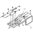
- CT system It is a perspective view of an example of CT system to which the present invention is applied. It is a perspective view of the chemical injection device shown in FIG. It is a perspective view which shows the injection
- a CT system 1000 includes a chemical injection device 100 and a CT device 300 that is a fluoroscopic imaging device.
- the CT apparatus 300 and the chemical injection device 100 are connected to each other so that data relating to the chemical injection in the chemical injection apparatus 100 can be transmitted to the CT apparatus 300.
- the CT apparatus 300 includes a scanner 301 that performs an imaging operation, and an imaging control unit 302 that controls the operation of the scanner 301.
- the imaging control unit 302 includes a scanner 301 and a chemical solution. It is arranged in a separate chamber from the injection device 100.
- the chemical injection device 100 includes an injection head 110 that is mounted on an upper portion of a stand 111 via an arm 112, and an injection control unit 101 that is connected to the injection head 110 with a cable 102.
- the injection control unit 101 includes a main operation panel 103, a touch panel 104 serving as a display unit and an input unit, a hand unit 107 serving as an auxiliary input unit connected to the main body of the injection control unit 101 with a cable 108, and the like. ing.
- the injection head 110 has two concave portions 114 formed as syringe holding portions on the upper surface of the head main body 113, and syringes 200 ⁇ / b> C and 200 ⁇ / b> P are detachably attached to the concave portions 114, respectively.
- the syringes 200 ⁇ / b> C and 200 ⁇ / b> P have a cylinder 210 and a piston 220.
- Each of the syringes 200C and 200P is filled with a chemical solution.
- one syringe 200C is filled with a contrast agent that can change the CT value of the subject by injection
- the other syringe 200P is filled with physiological saline. Can be filled.
- Connected to the distal ends of the two syringes 200C and 200P attached to the head main body 113 is a connecting tube 230 that merges into one at the middle and is provided with an injection needle at the distal end.
- the injection head 110 is provided with two piston drive mechanisms 130 that are driven independently of each other to operate the pistons 220 of the syringes 200 ⁇ / b> C and 200 ⁇ / b> P mounted in the recesses 114, corresponding to the recesses 114. .
- These piston driving mechanisms 130 operate the pistons 220 of the syringes 200C and 200P respectively attached to the recesses 114, thereby separately or simultaneously applying the contrast medium and the physiological saline filled in the syringes 200C and 200P to the subject. Can be injected.
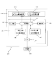
- FIG. 4 is a block diagram functionally showing the CT system 1000 of this embodiment.
- Each block shown in FIG. 4 exists as at least a part of the configuration described in FIGS. 1 to 3 or a combination of at least a part thereof, and may be configured as hardware or as a logic circuit. It may be configured.
- the injection control unit 101 includes a control unit 141, an input unit 142, a display unit 143, a test injection injection amount calculation unit 145, a main injection injection amount calculation unit 146, and an interface (I / F). 147.
- the chemical solution injection device 100 has two injection modes of test injection and main injection as injection modes of the chemical solution.
- the main injection is an injection of a contrast medium for imaging a CT image of a subject for diagnostic purposes.
- the test injection measures the time from the injection of the contrast medium to the target imaging site. For injection of contrast medium.
- the test injection is performed prior to the main injection, and a smaller amount of contrast agent is injected in the test injection than in the main injection.
- the input unit 142 corresponds to the main operation panel 103 and the touch panel 104 shown in FIG. 2, and includes various settings of the chemical injection device 100 by the operator and the maximum CT value obtained from the CT device 300 by the test injection. Accepts input of data necessary for determination of chemical injection conditions.
- the display unit 143 corresponds to the touch panel 104 shown in FIG. 2, and displays a setting screen, a data input screen, a screen representing an operation state, and the like of the chemical liquid injector 100. As described above, in this embodiment, the touch panel 104 has both the function as a part of the input unit 142 and the function of the display unit.
- the test injection injection amount calculation unit 145 calculates the contrast agent injection amount at the time of test injection based on the data input from the input unit 142, and the main injection injection amount calculation unit 145 is input from the input unit 142. Further, based on the maximum CT value obtained by the test injection, the amount of contrast medium injected at the time of the main injection is calculated.
- the control unit 141 controls each part of the injection control unit 101 and the injection head 110 so that the overall operation of the chemical solution injection apparatus 100 including the test injection and the main injection is operated according to a sequence including an operation procedure described later.
- the control unit 141 is connected to the CT apparatus 300 via the interface 147, and transmits a contrast medium injection start signal to the CT apparatus 300 simultaneously with the start of the test injection and the start of the main injection, respectively. .
- the input unit 142 and the display unit 143 can be provided not only in the injection control unit 101 but also in the injection head 110.
- the injection head 110 includes a plurality of operation buttons 116 as a part of the input unit 142 and a display panel 115 as a part of the display unit 143.
- the operation buttons 116 and the display panel 115 can be used for inputting and displaying data necessary for test injection, for example.
- the operator attaches the syringe 200C filled with the contrast medium and the syringe 200P filled with physiological saline to the predetermined recesses 114 of the injection head 110, respectively, and turns on the power of the drug solution injection device 100.
- the controller 141 advances each piston drive mechanism 130 at the most retracted position.
- the piston drive mechanism 130 holds the end of the piston 220 of the syringes 200 ⁇ / b> C and 200 ⁇ / b> P in the piston drive mechanism 130.
- Each syringe 200C, 200P is connected to an injection needle through an extension tube 230, and this injection needle is punctured by a subject.
- control unit 141 causes the display unit 143 to display a setting screen for test injection.
- the display unit 143 is a touch panel and also serves as the input unit 142 will be described as an example. Therefore, in the following description, the display unit 143 and the input unit 142 may be referred to as a touch panel.
- FIG. 5 shows an example of a test injection setting screen displayed on the display unit 143.
- a body group selection button group 151 On the setting screen 150 shown in FIG. 5, a body group selection button group 151, an imaging region selection button group 152, a weight input field 153, and a test injection start button 154 are displayed.
- the body classification selection button group 151 includes four buttons that divide an image simulating a subject who is supine into a head, a chest, a waist, and a leg, and an operator selects and touches one of these buttons. By doing so, the classification corresponding to the touched button is input. The selected button is highlighted. FIG. 5 shows a state where the chest is selected.
- the imaging region selection button group 152 has one or more buttons that specifically indicate the imaging region from the selected body segment that is displayed when the body segment is input. When the operator selects and touches a button representing a target imaging region, an imaging region corresponding to the touched region is input.
- FIG. 5 shows a state where the heart is selected as the imaging region.
- the body weight input field 153 is a field for inputting the subject's body weight numerically, and is ready for input after inputting the imaging region.
- the control unit 141 transmits the input weight data to the test injection amount calculation unit 145, and the test injection amount calculation unit 145 that has received the data is given in advance.
- An injection amount corresponding to the weight of the subject is calculated from the weight data according to the calculation formula. It is preferable that the amount of contrast medium injected at the time of test injection is as small as possible within a range where a contrast effect can be obtained so that the burden on the subject due to the test injection is reduced.
- the calculation formula of the contrast agent injection amount can be given by, for example, an expression obtained by multiplying the body weight by a predetermined coefficient, and this coefficient may be changed by the operator as necessary.
- the contrast medium injection amount at the time of test injection is obtained from the body weight of the subject, but in addition, at least a part of the liquid factor such as the body factor such as the subject's age, height, and sex, and the type of liquid medicine
- the amount of contrast medium injected at the time of test injection can be determined in consideration of the above.
- the contrast agent injection amount at the time of test injection can be adjusted according to the subject and the type of chemical solution Can do. This enables a test injection with a smaller contrast medium injection amount, and as a result, the physical burden on the subject due to the injection of the contrast medium in the test injection can be reduced.
- the test injection is for the purpose of measuring the arrival time of the contrast agent at the imaging site and the measurement of the maximum CT value, it is not necessary to strictly determine the contrast agent injection amount at the time of the test injection.
- the amount of contrast medium injected at the time of test injection may be a fixed value, making it unnecessary to input data such as the weight of the subject. In this case, the test injection amount calculator 145 is unnecessary.
- the control unit 141 moves the piston drive mechanism 130 forward.
- a protocol for injecting a contrast agent at a constant injection rate during a predetermined injection time is set as a contrast agent injection protocol.
- the amount of contrast medium injected is proportional to the moving distance of the piston drive mechanism 130. Therefore, the control unit 141 advances the piston drive mechanism 130 at a constant speed by a distance corresponding to the amount of contrast medium calculated by the test injection injection amount calculation unit 145 during a predetermined injection time.
- the injection time of the contrast agent can be set in advance according to, for example, the imaging region, but can be changed by the operator as necessary.
- a test injection start signal is transmitted from the control unit 141 to the CT apparatus 300 via the interface 147.
- the CT apparatus 300 executes a monitoring scan after a predetermined time has elapsed since the start of test injection. During the monitoring scan, the CT apparatus 300 measures CT values at regular time intervals and displays the results as a graph or an image.
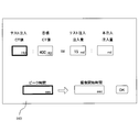
- the control unit 141 causes the touch panel to display a setting screen 160 for main injection as shown in FIG.
- a screen for inputting the maximum CT value at the time of test injection is displayed.
- C T is the increase in the maximum CT value due to the test injection
- C A is the increase in the maximum CT value due to the main injection
- I t is the contrast agent injection amount at the test injection
- I is the contrast agent injection amount at the main injection.
- the imaging region has a certain CT value even when the contrast agent is not injected, and the CT value measured by the CT apparatus 300 is the CT value before the contrast agent is injected. It is a value including. Therefore, the increase in the maximum CT value due to the injection of the contrast agent in the test injection and the main injection is C t , which is the maximum CT value obtained by the CT apparatus 300 in the test injection, and the target to be obtained by the CT apparatus 300 in the main injection
- C T C t ⁇ C 0 , respectively.
- C A C a -C 0 It becomes.
- the target maximum CT value C a is the maximum CT value with which the best contrast effect can be obtained, and this value can be set in advance based on statistical data or the like.
- the contrast agent injection amount and the maximum CT value obtained by the CT apparatus 300 at that time are known in the test injection. since, it is possible to determine the injection amount of the contrast medium as the target maximum CT value C a can be obtained in this injection very easily.
- an appropriate value corresponding to the imaging region can be stored in advance in the control unit 141 based on statistical data. Accordingly, the operator need only maximum CT value C t obtained in the test injection to input to the touch panel.
- the setting screen 160 shown in FIG. 6 displays the proportional expression in which the value to be input and the calculated value are blank.
- the maximum CT value including the CT value before the contrast agent injection is used instead of the increase in the maximum CT value.
- the injection amount calculation unit 146 for main injection subtracts the CT value before the contrast agent injection from the input maximum CT value and the set target maximum CT value, respectively. The contrast medium injection amount is calculated.
- an elapsed time from the start of test injection when the maximum CT value is reached by test injection is input as a peak time. It is supposed to be.
- the control unit 141 causes the setting screen 160 to display the imaging start time of the main scan executed by the CT apparatus 300 corresponding to the main injection.
- the imaging start time can be, for example, 2 seconds before the CT value peak time. Thereby, since imaging can be performed in a period including the peak time of the CT value, a good contrast effect can be obtained. How many seconds before the peak time of the CT value is started may be determined in advance, but can be changed by the operator as necessary.
- the control unit 141 may correct the peak time of the CT value obtained by the test injection based on the contrast agent injection amount in the main injection calculated by the main injection amount calculation unit 146. In that case, the control unit 141 can set the imaging start time based on the corrected peak time.
- the control unit 141 transmits the data to the CT apparatus 300 through the interface 147.
- the CT apparatus 300 can execute the main scan, for example, for 4 seconds from the imaging start time.
- the imaging start time after the main injection can be determined in advance in consideration of the difference between the start of the injection of the contrast agent and the arrival of the maximum CT value between the test injection and the main injection. In that case, it is not necessary to input the peak time in the test injection.
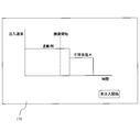
- the control unit 141 displays a main injection confirmation screen 170 as shown in FIG. 7 on the touch panel, for example.
- the main injection confirmation screen 170 displays an injection graph representing the relationship between the elapsed time from the start of injection and the injection speed of the chemical solution injected by the main injection. Furthermore, the imaging start time is also displayed on this graph, so that the imaging timing can be seen at a glance.
- the main injection is performed by the same protocol as the test injection in which the contrast medium is injected at a constant injection speed during a predetermined injection time.
- the injection time is the same as the injection time in the test injection, but the injection speed is different from the test injection.
- the amount of contrast medium injected in the main injection is larger than that in the test injection, the contrast medium is injected at a higher injection rate than in the test injection.
- a predetermined amount of physiological saline is injected at a preset injection rate.
- the control unit 141 controls the two piston drive mechanisms 113 so that the contrast medium and the physiological saline are injected into the subject according to the above-described protocol, whereby the main injection is performed.
- a main injection start signal is transmitted from the control unit 141 to the CT apparatus 300 via the interface 147.
- the CT apparatus 300 performs the main scan after the start of the main injection after the imaging start time set by the chemical injection device 100 based on the result of the test injection. By the main scan, a CT image of the subject at the target imaging site is captured.
- the contrast agent injection amount in the main injection is determined using the maximum CT value measured in the test injection.
- the maximum CT value obtained by the test injection reflects individual differences such as the circulating blood volume, cardiac output, and vascular resistance of the test subject. Therefore, it is possible to set the optimum injection amount of the contrast medium according to the individual difference very easily.
- the test injection is a process that is normally performed prior to the main injection in order to measure the time for the contrast medium to reach the imaging region, the number of processes is not newly increased by performing the test injection.
- control unit 141 is configured to be able to receive the maximum CT value data from the CT apparatus through the interface 147 after the test injection, and the received maximum CT value data is input to the test injection amount calculation unit 145. It can also be. This eliminates the need for the operator to input the maximum CT value.
- the number of the liquid syringes that can be mounted on the injection head 110 may be one or three or more. It may be.
- the concave portions 114, the piston drive mechanisms 130, and the like are provided in a number corresponding to the number of chemical syringes to be mounted.
- the size of the chemical syringe that can be attached to the injection head 110 is also arbitrary, and the size of the recess 114, the stroke of the rod 131, and the like are set so as to match the size of the chemical syringe to be attached.
- the sizes of the chemical solution syringes may be different from each other.
Landscapes
- Health & Medical Sciences (AREA)
- Life Sciences & Earth Sciences (AREA)
- Engineering & Computer Science (AREA)
- Medical Informatics (AREA)
- Public Health (AREA)
- Biomedical Technology (AREA)
- Heart & Thoracic Surgery (AREA)
- Veterinary Medicine (AREA)
- Animal Behavior & Ethology (AREA)
- General Health & Medical Sciences (AREA)
- Pathology (AREA)
- Optics & Photonics (AREA)
- Physics & Mathematics (AREA)
- Biophysics (AREA)
- High Energy & Nuclear Physics (AREA)
- Surgery (AREA)
- Nuclear Medicine, Radiotherapy & Molecular Imaging (AREA)
- Molecular Biology (AREA)
- Radiology & Medical Imaging (AREA)
- Vascular Medicine (AREA)
- Hematology (AREA)
- Anesthesiology (AREA)
- Pulmonology (AREA)
- Theoretical Computer Science (AREA)
- Apparatus For Radiation Diagnosis (AREA)
- Infusion, Injection, And Reservoir Apparatuses (AREA)
Abstract
L'invention porte sur un dispositif d'injection de solution médicale (100) qui comporte une tête d'injection (110) sur laquelle une seringue remplie d'un agent de contraste est montée, et une unité de commande d'injection (101) comprenant une section de commande (141) qui commande un fonctionnement de la tête d'injection (110). L'unité de commande d'injection (101) comprend une section d'opération de quantité d'injection réelle (146) pour calculer une quantité d'injection d'agent de contraste pour une injection réelle de telle sorte que la valeur CT maximale obtenue dans l'injection réelle devient une valeur prédéterminée conformément à la valeur CT maximale obtenue par un dispositif CT (300) dans une injection de test. La section de commande (141) commande la tête d'injection (110), à l'injection réelle, de façon à injecter l'agent de contraste de la quantité calculée par l'unité d'opération de quantité d'injection réelle (146).
Priority Applications (1)
| Application Number | Priority Date | Filing Date | Title |
|---|---|---|---|
| JP2010505969A JP5394371B2 (ja) | 2008-04-02 | 2009-04-01 | 薬液注入装置 |
Applications Claiming Priority (2)
| Application Number | Priority Date | Filing Date | Title |
|---|---|---|---|
| JP2008-096088 | 2008-04-02 | ||
| JP2008096088 | 2008-04-02 |
Publications (1)
| Publication Number | Publication Date |
|---|---|
| WO2009123256A1 true WO2009123256A1 (fr) | 2009-10-08 |
Family
ID=41135623
Family Applications (1)
| Application Number | Title | Priority Date | Filing Date |
|---|---|---|---|
| PCT/JP2009/056795 Ceased WO2009123256A1 (fr) | 2008-04-02 | 2009-04-01 | Dispositif d'injection de solution médicale |
Country Status (2)
| Country | Link |
|---|---|
| JP (2) | JP5394371B2 (fr) |
| WO (1) | WO2009123256A1 (fr) |
Cited By (4)
| Publication number | Priority date | Publication date | Assignee | Title |
|---|---|---|---|---|
| JP2012090979A (ja) * | 2010-10-26 | 2012-05-17 | Siemens Ag | 医用画像形成時の造影剤量の決定装置 |
| JP2013540535A (ja) * | 2010-10-20 | 2013-11-07 | メドトロニック ナビゲーション,インコーポレイテッド | 画像投影の再構築のための方法および装置 |
| US9769912B2 (en) | 2010-10-20 | 2017-09-19 | Medtronic Navigation, Inc. | Gated image acquisition and patient model construction |
| US9807860B2 (en) | 2010-10-20 | 2017-10-31 | Medtronic Navigation, Inc. | Gated image acquisition and patient model construction |
Families Citing this family (3)
| Publication number | Priority date | Publication date | Assignee | Title |
|---|---|---|---|---|
| US11406333B2 (en) | 2016-05-09 | 2022-08-09 | Canon Medical Systems Corporation | Medical image diagnosis apparatus and management apparatus |
| JP6765047B2 (ja) * | 2016-06-28 | 2020-10-07 | 株式会社根本杏林堂 | 注入システム、データ処理装置及び注入装置 |
| JP7023482B2 (ja) * | 2017-06-20 | 2022-02-22 | 株式会社根本杏林堂 | 生成装置、注入装置、及び注入量決定方法 |
Citations (2)
| Publication number | Priority date | Publication date | Assignee | Title |
|---|---|---|---|---|
| WO2006058280A2 (fr) * | 2004-11-24 | 2006-06-01 | Medrad, Inc. | Dispositifs, systemes et methodes de distribution de liquide |
| JP2006141497A (ja) * | 2004-11-17 | 2006-06-08 | Medrad Inc | 患部を描画する方法及び患部描画システム |
Family Cites Families (3)
| Publication number | Priority date | Publication date | Assignee | Title |
|---|---|---|---|---|
| JP4620929B2 (ja) * | 2002-09-26 | 2011-01-26 | 株式会社根本杏林堂 | 薬液注入装置 |
| JP4086309B2 (ja) * | 2005-11-28 | 2008-05-14 | 財団法人ひろしま産業振興機構 | 造影剤注入プロトコル決定方法および造影剤注入プロトコル演算装置 |
| WO2007116862A1 (fr) * | 2006-04-05 | 2007-10-18 | Nemoto Kyorindo Co., Ltd. | Dispositif d'injection de médicament liquide |
-
2009
- 2009-04-01 WO PCT/JP2009/056795 patent/WO2009123256A1/fr not_active Ceased
- 2009-04-01 JP JP2010505969A patent/JP5394371B2/ja not_active Expired - Fee Related
-
2013
- 2013-10-16 JP JP2013215400A patent/JP6000926B2/ja not_active Expired - Fee Related
Patent Citations (2)
| Publication number | Priority date | Publication date | Assignee | Title |
|---|---|---|---|---|
| JP2006141497A (ja) * | 2004-11-17 | 2006-06-08 | Medrad Inc | 患部を描画する方法及び患部描画システム |
| WO2006058280A2 (fr) * | 2004-11-24 | 2006-06-01 | Medrad, Inc. | Dispositifs, systemes et methodes de distribution de liquide |
Cited By (7)
| Publication number | Priority date | Publication date | Assignee | Title |
|---|---|---|---|---|
| JP2013540535A (ja) * | 2010-10-20 | 2013-11-07 | メドトロニック ナビゲーション,インコーポレイテッド | 画像投影の再構築のための方法および装置 |
| US9769912B2 (en) | 2010-10-20 | 2017-09-19 | Medtronic Navigation, Inc. | Gated image acquisition and patient model construction |
| US9807860B2 (en) | 2010-10-20 | 2017-10-31 | Medtronic Navigation, Inc. | Gated image acquisition and patient model construction |
| US11969279B2 (en) | 2010-10-20 | 2024-04-30 | Medtronic Navigation, Inc. | Method and apparatus for reconstructing image projections |
| US12120806B2 (en) | 2010-10-20 | 2024-10-15 | Medtronic Navigation, Inc. | Gated image acquisition and patient model construction |
| US12635962B2 (en) | 2010-10-20 | 2026-05-26 | Medtronic Navigation, Inc. | Method and apparatus for reconstructing image projections |
| JP2012090979A (ja) * | 2010-10-26 | 2012-05-17 | Siemens Ag | 医用画像形成時の造影剤量の決定装置 |
Also Published As
| Publication number | Publication date |
|---|---|
| JP6000926B2 (ja) | 2016-10-05 |
| JP2014014715A (ja) | 2014-01-30 |
| JP5394371B2 (ja) | 2014-01-22 |
| JPWO2009123256A1 (ja) | 2011-07-28 |
Similar Documents
| Publication | Publication Date | Title |
|---|---|---|
| JP6745847B2 (ja) | Ctシステム、ctシステムの作動方法およびctシステムの作動方法を実行させる一つまたは複数のコンピュータプログラム | |
| JP5416761B2 (ja) | 薬液注入装置およびx線ctシステム | |
| JP6000926B2 (ja) | 薬液注入装置 | |
| JP5897806B2 (ja) | 注入装置 | |
| US6397097B1 (en) | Method and control apparatus for tracking a contrast agent in an examination subject using a medical imaging device | |
| JP5203971B2 (ja) | 薬液注入装置 | |
| JP5227189B2 (ja) | 薬液注入装置および薬液注入方法 | |
| JP6618673B2 (ja) | 注入プロトコル設定装置、薬液注入装置および医療システム | |
| JP7714261B2 (ja) | 造影剤注入システム | |
| CN102551778B (zh) | 用于确定医学成像中的造影剂量的装置 | |
| US20090312695A1 (en) | Automatic Heart Rate Triggering of Injection of Radiopharmaceuticals for Nuclear Stress Test | |
| JP5897907B2 (ja) | 薬液注入装置および透視撮像システム | |
| JP2012232029A (ja) | 薬液注入装置および撮像システム | |
| WO2007097422A1 (fr) | Unite d'injection de liquide | |
| CN108992743B (zh) | 一种自动生成注射计划的注射方法及设备 | |
| JPWO2008099876A1 (ja) | 薬液注入装置およびct装置 | |
| JPWO2008126854A1 (ja) | 薬液注入装置 | |
| JP7711910B2 (ja) | 報知システム、報知システムの制御方法、及び報知プログラム | |
| JP5523957B2 (ja) | 造影剤注入条件を決定する機能を備えた医療装置 | |
| EP2113267A1 (fr) | Déclenchement automatique par fréquence cardiaque de l'injection d'agents radiopharmaceutiques pour test de stress cardiaque | |
| JP2016187538A (ja) | 心拍出量測定装置 |
Legal Events
| Date | Code | Title | Description |
|---|---|---|---|
| 121 | Ep: the epo has been informed by wipo that ep was designated in this application |
Ref document number: 09726889 Country of ref document: EP Kind code of ref document: A1 |
|
| WWE | Wipo information: entry into national phase |
Ref document number: 2010505969 Country of ref document: JP |
|
| NENP | Non-entry into the national phase |
Ref country code: DE |
|
| 122 | Ep: pct application non-entry in european phase |
Ref document number: 09726889 Country of ref document: EP Kind code of ref document: A1 |