WO2009128510A1 - レーザー発振装置 - Google Patents
レーザー発振装置 Download PDFInfo
- Publication number
- WO2009128510A1 WO2009128510A1 PCT/JP2009/057671 JP2009057671W WO2009128510A1 WO 2009128510 A1 WO2009128510 A1 WO 2009128510A1 JP 2009057671 W JP2009057671 W JP 2009057671W WO 2009128510 A1 WO2009128510 A1 WO 2009128510A1
- Authority
- WO
- WIPO (PCT)
- Prior art keywords
- laser
- sunlight
- laser medium
- light guide
- light
- Prior art date
- Legal status (The legal status is an assumption and is not a legal conclusion. Google has not performed a legal analysis and makes no representation as to the accuracy of the status listed.)
- Ceased
Links
Images







Classifications
-
- H—ELECTRICITY
- H01—ELECTRIC ELEMENTS
- H01S—DEVICES USING THE PROCESS OF LIGHT AMPLIFICATION BY STIMULATED EMISSION OF RADIATION [LASER] TO AMPLIFY OR GENERATE LIGHT; DEVICES USING STIMULATED EMISSION OF ELECTROMAGNETIC RADIATION IN WAVE RANGES OTHER THAN OPTICAL
- H01S3/00—Lasers, i.e. devices using stimulated emission of electromagnetic radiation in the infrared, visible or ultraviolet wave range
- H01S3/09—Processes or apparatus for excitation, e.g. pumping
- H01S3/091—Processes or apparatus for excitation, e.g. pumping using optical pumping
- H01S3/0915—Processes or apparatus for excitation, e.g. pumping using optical pumping by incoherent light
-
- H—ELECTRICITY
- H01—ELECTRIC ELEMENTS
- H01S—DEVICES USING THE PROCESS OF LIGHT AMPLIFICATION BY STIMULATED EMISSION OF RADIATION [LASER] TO AMPLIFY OR GENERATE LIGHT; DEVICES USING STIMULATED EMISSION OF ELECTROMAGNETIC RADIATION IN WAVE RANGES OTHER THAN OPTICAL
- H01S3/00—Lasers, i.e. devices using stimulated emission of electromagnetic radiation in the infrared, visible or ultraviolet wave range
- H01S3/02—Constructional details
- H01S3/04—Arrangements for thermal management
- H01S3/0407—Liquid cooling, e.g. by water
-
- H—ELECTRICITY
- H01—ELECTRIC ELEMENTS
- H01S—DEVICES USING THE PROCESS OF LIGHT AMPLIFICATION BY STIMULATED EMISSION OF RADIATION [LASER] TO AMPLIFY OR GENERATE LIGHT; DEVICES USING STIMULATED EMISSION OF ELECTROMAGNETIC RADIATION IN WAVE RANGES OTHER THAN OPTICAL
- H01S3/00—Lasers, i.e. devices using stimulated emission of electromagnetic radiation in the infrared, visible or ultraviolet wave range
- H01S3/05—Construction or shape of optical resonators; Accommodation of active medium therein; Shape of active medium
- H01S3/06—Construction or shape of active medium
- H01S3/0602—Crystal lasers or glass lasers
- H01S3/0606—Crystal lasers or glass lasers with polygonal cross-section, e.g. slab, prism
-
- H—ELECTRICITY
- H01—ELECTRIC ELEMENTS
- H01S—DEVICES USING THE PROCESS OF LIGHT AMPLIFICATION BY STIMULATED EMISSION OF RADIATION [LASER] TO AMPLIFY OR GENERATE LIGHT; DEVICES USING STIMULATED EMISSION OF ELECTROMAGNETIC RADIATION IN WAVE RANGES OTHER THAN OPTICAL
- H01S3/00—Lasers, i.e. devices using stimulated emission of electromagnetic radiation in the infrared, visible or ultraviolet wave range
- H01S3/05—Construction or shape of optical resonators; Accommodation of active medium therein; Shape of active medium
- H01S3/08—Construction or shape of optical resonators or components thereof
- H01S3/08072—Thermal lensing or thermally induced birefringence; Compensation thereof
-
- H—ELECTRICITY
- H01—ELECTRIC ELEMENTS
- H01S—DEVICES USING THE PROCESS OF LIGHT AMPLIFICATION BY STIMULATED EMISSION OF RADIATION [LASER] TO AMPLIFY OR GENERATE LIGHT; DEVICES USING STIMULATED EMISSION OF ELECTROMAGNETIC RADIATION IN WAVE RANGES OTHER THAN OPTICAL
- H01S3/00—Lasers, i.e. devices using stimulated emission of electromagnetic radiation in the infrared, visible or ultraviolet wave range
- H01S3/09—Processes or apparatus for excitation, e.g. pumping
- H01S3/091—Processes or apparatus for excitation, e.g. pumping using optical pumping
- H01S3/094—Processes or apparatus for excitation, e.g. pumping using optical pumping by coherent light
- H01S3/094049—Guiding of the pump light
- H01S3/094057—Guiding of the pump light by tapered duct or homogenized light pipe, e.g. for concentrating pump light
Definitions
- the present invention relates to a laser oscillation device excited by sunlight.
- Patent Document 1 discloses a solar direct excitation laser oscillation device including a laser rod made of a laser oscillation medium that directly oscillates with sunlight as excitation light in order to appropriately perform thermal control of the laser rod in outer space.
- the laser oscillation apparatus provided with the cooling means which has a pipe line through which the refrigerant
- the present invention has been made to solve the above-described problems, and an object of the present invention is to provide a laser oscillation device that further improves the conversion efficiency from sunlight to laser light.
- the invention according to claim 1 is a laser medium that is excited by sunlight and outputs laser light, and an output mirror having a concave surface facing the output end of the laser medium, A light guide having a reflection surface extending outward from the laser medium from an output end of the laser medium, and reflecting the sunlight to the laser medium.
- the invention according to claim 2 is the laser oscillation device according to claim 1, wherein the reflecting surface of the light guide is a conical surface.
- the invention according to claim 3 is characterized in that, in the laser oscillation device according to claim 1 or 2, the laser medium has an opening extending in an optical axis direction of the laser medium.
- the laser oscillation device according to any one of the first to third aspects, further comprising a condensing unit that condenses the sunlight and enters the light guide. It is characterized by having.
- the invention according to claim 5 is the laser oscillation device according to claim 4, wherein the optical axis of the condensing means is arranged obliquely with respect to the optical axis of the laser medium. To do.
- the surface of the incident window of the light guide that takes in the sunlight is arranged perpendicular to the optical axis of the light collecting means. It is characterized by that.
- the invention according to claim 7 is the laser oscillation device according to any one of claims 4 to 6, wherein the condensing means is a Fresnel lens, and a fluorescent substance is added to the Fresnel lens. It is characterized by that.
- the invention according to claim 8 is the laser oscillation apparatus according to claim 7, wherein the Fresnel lens is surface-modified by deep ultraviolet light.
- the invention described in claim 9 includes a laser medium that is excited by sunlight and outputs laser light, and the laser medium has an opening that extends in an optical axis direction of the laser medium. .
- the invention according to claim 10 is the laser oscillation device according to claim 9, wherein the opening has a slit.
- the invention according to claim 11 is the laser oscillation device according to claim 9 or 10, wherein the laser medium is formed in a plate shape.
- the invention according to claim 12 includes a laser medium that is excited by sunlight and outputs laser light, and a reflecting surface that extends outward from the laser medium from an output end of the laser medium, A light guide that reflects sunlight and guides it to the laser medium; and a condensing unit that condenses the sunlight and makes it incident on the light guide. It is arranged obliquely with respect to the optical axis.
- a laser medium that is excited by sunlight to output laser light
- an output mirror having a concave surface that faces the output end of the laser medium, and an outer side of the laser medium from the output end of the laser medium.
- a light guide that reflects sunlight and guides it to the laser medium, thereby increasing the mode volume in the vicinity of the output end of the laser medium. Therefore, a laser oscillation device that can further improve the conversion efficiency from sunlight to laser light can be provided.
- FIG. 1 It is a schematic diagram which shows the pattern of the sunlight condensed by the Fresnel lens of FIG. It is a perspective view which shows the modification of the light guide of FIG. It is a schematic diagram which shows the manufacturing process of the modification of the light guide of FIG. It is a perspective view which shows the other modification of the light guide of FIG. It is a perspective view which shows the modification of the laser medium of FIG. It is a schematic diagram which shows the example of a schematic structure of the light guide and laser medium in a present Example. It is a diagram which shows the laser output characteristic of a present Example. It is explanatory drawing which shows the performance comparison with a present Example and a prior art.
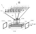
- FIG. 1 is a schematic diagram showing a schematic configuration example of a laser oscillation apparatus according to the first embodiment of the present invention.
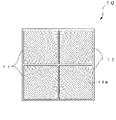
- FIG. 2 is a plan view showing a Fresnel lens used in the laser oscillation device.
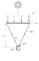
- FIG. 3 is a schematic diagram showing a state of light collection by the Fresnel lens.
- FIG. 4 is a schematic diagram showing a light guide and a laser cavity of the laser oscillation device.
- a solar-excited laser oscillation device 1 includes a Fresnel lens 10 that collects sunlight S, a light guide 20 that guides the collected sunlight Sf as laser excitation light, and a light guide 20. And a laser cavity 30 that resonates the laser beam. Then, the laser oscillation device 1 irradiates the generated laser light to the magnesium oxide (MgO) target 5 to generate magnesium (Mg) vapor, thereby obtaining magnesium from the magnesium oxide.
- MgO magnesium oxide
- the Fresnel lens 10 is a four-split Fresnel lens configured by combining four 1-m square split lenses 11. Since the Fresnel lens condenses sunlight by a refraction method, a groove 11a as shown in FIG. 2 is formed on one surface of the plastic. The groove 11a is formed on the exit surface of the split lens 11 so as to reduce the reflection loss. The entrance / exit surface of the split lens 11 is subjected to surface treatment using an excimer lamp that emits light in the deep ultraviolet wavelength region so that the scattering loss is several percent or less. A dielectric optical thin film is vapor-deposited on the surface of the splitting lens 11 using the patented technology for forming an optical thin film (Patent No.
- the Fresnel lens 10 is surface-modified with deep ultraviolet light.
- the number of divisions of the Fresnel lens 10 is not limited to four, and the shape of the division lens 11 is not limited to a square, and the division lens 11 may be combined to produce the effect of the Fresnel lens 10.
- the light guide 20 is arranged so that the vicinity of the end of the laser cavity 30 is located at the focal position of the Fresnel lens 10 having a focal length f. That is, the laser housing 25 having the light guide 20 therein is disposed.
- the Fresnel lens 10 condenses the sunlight S at the center of the light guide 20 (the center of the laser housing 25). Further, the optical axis of the Fresnel lens 10 is parallel to the optical axis of the laser medium 31.
- the Fresnel lens 10 functions as an example of a condensing unit that condenses the sunlight S and makes it incident on the light guide 20.
- the light guide 20 houses a sunlight incident window 21 that transmits the concentrated sunlight Sf, a reflection surface 22 that reflects the sunlight Sf, and a laser cavity 30.
- a laser housing 25 A laser housing 25.
- the sunlight incident window 21 is disposed perpendicular to the vertically incident light Sf1 incident in parallel to the optical axis of the Fresnel lens 10.
- the surface of the incident window of the light guide 20 that takes in the sunlight Sf is arranged perpendicular to the optical axis of the Fresnel lens 10.
- the reflection surface 22 is formed on the inner surface of the laser housing 25 so as to be a conical surface, which is an example of a conical surface, and the bottom surface of the cone is the sunlight incident window 21 side.
- a highly reflective metal film is corroded by cooling water, and a dielectric multilayer film that does not absorb sunlight is deposited in order to prevent a decrease in reflectance.
- an Al or Ag mirror with a water-resistant thin film or a reflecting mirror in which a dielectric multilayer film is coated on an Al or Ag film is used, and the reflectance is 95% or more.
- the light guide 20 has the reflection surface 22 extending from the output end of the laser medium 31 to the outside of the laser medium, and reflects the sunlight S and guides it to the laser medium.
- the condensing diameter of the sunlight Sf condensed by the Fresnel lens 10 is about 50 mm ⁇ near the focal point, it is indispensable to provide the light guide 20.
- the light guide 20 is installed near the condensing point of the Fresnel lens 10 and serves to guide the sunlight Sf collected by the Fresnel lens 10 to the laser cavity 30 with high efficiency.
- the laser housing (housing) 25 has a space 27 formed by the sunlight incident window 21 and the reflecting surface 22, and the space 27 is filled with the cooling water W.
- the laser housing 25 has a cooling water inlet / outlet 26 and is configured to supply and discharge the cooling water W from the outside to the space 27.
- the cooling water inlet / outlet 26 penetrates the laser housing 25 and reaches the space 27 so as to be connected to the space 27 from the outside.
- the material of the laser housing 25 is metal, plastic, glass, ceramic, or the like.
- the laser cavity 30 is a laser medium 31 that is excited by sunlight and outputs laser light, an end of the laser medium 31, and the sunlight entrance window 21.
- HR highly reflective film
- AR antireflection film
- an output mirror 35 installed.
- the material of the laser medium 31 is YAG (Y 3 Al 5 O 12 ), GSGG (Gd 3 Ac 2 Al 3 O 12 ) co-doped with Nd and Cr, or YAG, GSGG, GGG (doped with high concentration Nd). Solid laser crystal (or ceramic) such as Gd 3 Ga 5 O 12 ).
- the shape of the laser medium 31 is a rod having a circular cross section.
- the highly reflective film 32 is formed by depositing a dielectric multilayer film that highly reflects at the oscillation wavelength of the laser medium. For example, when a YAG crystal is used, a highly reflective film (reflectance: 99% or more) for a wavelength of 1.064 ⁇ m is formed by vapor deposition. The highly reflective film 32 reflects only the light having a wavelength of 1.064 ⁇ m excited in the laser medium 31, and is incident through the other wavelength light, that is, the sunlight incident window 21. Most of the coming sunlight passes through the highly reflective film 32 and enters the laser medium 31.
- the antireflection film 33 is formed by vapor deposition of an antireflection film for a wavelength of 1.064 ⁇ m (reflectance: 0.2% or less).
- the antireflection film 33 prevents reflection loss in the laser cavity 30 and oscillation of other modes.
- the output mirror 35 has a concave surface 35a that faces the output end of the laser medium 31, as shown in FIG.
- the concave surface 35a of the output mirror 35 has an effect of correcting the thermal lens effect of the laser medium 31.
- Laser light grown in the laser cavity 30 is output from the output mirror 35 to the outside. Since the output of the laser greatly depends on the radius of curvature and the reflectance of the concave surface 35a of the output mirror 35, the output mirror 35 is configured to be easily adjusted.
- the laser medium 31 is optically pumped by sunlight Sf.
- the sunlight Sf that has passed through the highly reflective film 32 enters the laser medium 31 to excite the laser medium 31 (axial excitation), and the sunlight Sf reflected by the reflecting surface 22 of the light guide 20
- the laser medium 31 enters the laser medium 31 from the side surface to excite the laser medium 31 (side surface excitation).
- FIG. 5 is a schematic diagram showing a state of light collection in the light guide 20 when (A) the light is reflected in the vicinity of the end face of the reflecting surface and (B) the light is reflected at the back of the reflecting surface.
- FIG. 6 is a schematic diagram showing the mode volume and the intensity distribution of incident light in the laser medium 31.
- FIG. 7 is a schematic diagram showing a pattern of sunlight condensed by the Fresnel lens 10.
- the sunlight S is collected by the Fresnel lens 10 and passes through the sunlight incident window 21 and enters the light guide 20 as sunlight Sf.
- the condensed incident light is reduced in the diameter of sunlight Sf until it is substantially equal to the diameter of the laser medium 31, and is incident from the end of the laser medium 31 where the highly reflective film 32 is formed. Is excited in the axial direction.
- the other sunlight Sf is reflected by the reflection surface 22 of the light guide 20 and enters the laser medium 31 from the side surface of the laser medium 31 to excite the laser medium 31 on the side surface.
- the vertically incident light Sf1 incident perpendicularly to the end face of the sunlight incident window 21 or the laser medium 31 is 1
- Both the reflected light of the second time and the reflected light of the second time are gathered relatively toward the bottom of the light guide 20 (near the output end of the laser medium 31).
- the oblique incident light Sf2 also has its optical path reaching the bottom of the light guide due to the first reflection.
- the oblique incident light Sf2 shown in FIG. 5 is an example of oblique incident light having various angles.
- the mode volume Bv increases from the end of the laser medium 31 where the high reflection film 32 is located toward the end of the laser medium 31 where the antireflection film 33 is located. This is due to the concave surface 35a of the output mirror 35 that corrects the thermal lens effect.
- the laser medium 31 has a peak of intensity Bi at which incident light enters the laser medium 31 toward the output end.
- the sunlight reflected by the reflecting surface 22 is likely to gather near the bottom of the light guide 20 due to the configuration of the light guide 20.
- the Fresnel lens 10 cannot sufficiently squeeze the sunlight S, and the sunlight is on the side of the laser medium 31 and It becomes easier to gather at the output end. Therefore, since the mode volume is larger at the output end of the laser medium 31, the laser oscillation device 1 can improve the conversion efficiency from sunlight to laser light even when the intensity of sunlight is weak due to clouds or the like. It is a configuration that can be achieved.
- the cooling water W flows from the cooling water inlet / outlet 26 toward the output end of the laser medium 31 where sunlight tends to gather,
- the cooling water W flows out of the cooling water inlet / outlet 26 toward the light incident window 21 and takes heat.
- the sunlight Sf incident on the light guide 20 is a component of the region a (parallel light condensing region) collected as parallel light among the components incident on the Fresnel lens 10, And it is divided roughly into two components of the area
- the laser medium 31 that is excited by the sunlight Sf and outputs laser light the output mirror 35 having the concave surface 35 a facing the output end of the laser medium 31, and the laser medium 31
- the output end of the laser medium 31 is provided with a light guide 20 having a reflection surface 22 extending outward from the output end and reflecting the sunlight Sf to the laser medium 31. Since the mode volume increases in the vicinity, and sunlight from the light guide 20 gathers there, the laser oscillation device 1 that can further improve the conversion efficiency from sunlight to laser light can be provided. In particular, even when the intensity of sunlight is weak due to clouds or the like, the laser oscillation device 1 can improve the conversion efficiency from sunlight to laser light. Further, since the laser oscillation device 1 converts sunlight into laser light, the metal is purified by processing metal or plastic, or by heating and reducing an oxide material such as magnesium oxide to a high temperature. Available to:
- the Fresnel lens 10 is further provided as an example of a condensing unit that condenses sunlight and enters the light guide 20, sunlight is easily collected in the laser medium 31, and the conversion efficiency to laser light is improved. I can plan.
- the area of the Fresnel lens 10 is 4 m 2 , 4 kW sunlight power can be used for laser excitation. Therefore, when the groove of the Fresnel lens is formed on the incident surface, the maximum incident angle is about 75 ° and the reflection loss is increased. On the other hand, when a groove is formed on the exit surface, the maximum exit angle is about 45 °, so the reflection loss is somewhat improved.
- At least sunlight passing through the Fresnel lens has a power reduction of about 30% due to reflection loss, scattering loss, and absorption loss.
- the Fresnel lens 10 has a square shape in consideration of lens mounting on the lens holder. Since the maximum size of the single-piece split lens 11 is about 1 m due to manufacturing difficulties and costs, the present invention forms the large-diameter Fresnel lens 10 by the split method. Moreover, since plastic is used as the material, it is lightweight, easy to install, and easy to follow the sun.
- the reflection loss in the sunlight incident window 21 is reduced.
- the Fresnel lens 10 is made of a plastic, such as rhodamine 6G or DOTCI, to which a fluorescent material is added, the plastic as the material of the Fresnel lens is deteriorated by light in the ultraviolet wavelength region contained in sunlight.
- the laser oscillation efficiency can be improved by converting the ultraviolet light into effective excitation light in the visible wavelength region.
- the scattering loss is several percent or less.
- the total loss of sunlight transmitted through the Fresnel lens 10 can be reduced to at least 10% or less.
- a lamp light source such as a Kr arc lamp or a Xe flash lamp, or a semiconductor laser (LD) is used as an excitation light source of the YAG laser.
- the excitation efficiency for obtaining a high output of several hundred W or more with this YAG laser is about 5% at the maximum in the case of using a lamp light source. %. Therefore, in order to generate an output of 1 kW from the YAG laser, an electric input to the lamp of 20 kW is required, and about 3.3 kW is required for the LD.
- the laser oscillation device 1 of the present embodiment can provide a solid-state laser oscillation device that oscillates by sunlight excitation, which is representative of natural energy.
- the energy of sunlight is 1 kW / m2
- the average sunshine duration in Japan is about 4 hours / day, but when looking around the world, the area of sunshine duration is 8 hours / day is wide. For this reason, practical application of a laser using sunlight as an excitation light source is very promising.
- 4 kW of sunlight is required when the excitation efficiency is assumed to be 25%.
- this embodiment has been solved by a split-type Fresnel lens 10 configured by combining split lenses 11 as a technique for manufacturing a large-area Fresnel lens. .
- the spectrum of sunlight covers a wide wavelength range from 300 nm to the near-infrared wavelength range, and the absorption range of Nd ions that are the emission source of the Nd: YAG laser is 500 to 850 nm.
- the intensity is very high, it is excellent as a light source for excitation, but there remains a problem of effectively using light in the wavelength region of 400 to 550 nm that does not contribute much to the absorption of Nd ions.
- the lens material absorbs sunlight in the wavelength region of 400 to 550 nm that is hardly absorbed by trivalent Nd ions that are added to the laser medium and emit laser light.
- the dye Rhodamine 6G that emits light in the Nd ion absorption wavelength range 570 to 600 nm or the dye DOTCI that absorbs sunlight in the wavelength range 400 to 700 nm and emits light in the Nd ion absorption wavelength range 790 to 820 nm is added.
- the laser oscillation efficiency can be doubled.
- the solar-excited laser oscillation device 1 uses a Fresnel lens made of plastic or glass material to collect sunlight.
- the laser oscillation device 1 is configured to oscillate a solid-state laser by collecting sunlight with a Fresnel lens made of plastic or glass material.
- an antireflection film for preventing the reflection of sunlight was deposited on both surfaces of the Fresnel lens 10 to maximize the sunlight incident on the laser medium. That is, the laser oscillation device 1 deposits an antireflection film with little reflection loss against oblique incident light on both surfaces of the sunlight condensing Fresnel lens 10 so that the sunlight incident on the laser medium is maximized. It was configured as follows.
- the processed surface of the Fresnel lens 10 is surface-modified by deep ultraviolet light (wavelength 170 to 210 nm) such as an excimer lamp so that the scattering loss on the processed surface is minimized. That is, the processed surface of the Fresnel lens 10 is surface-treated with deep ultraviolet light to minimize the scattering loss of incident sunlight.
- deep ultraviolet light wavelength 170 to 210 nm
- the laser oscillation device 1 collects sunlight by forming a single Fresnel lens by combining the divided (2 to 6) parts. That is, the laser oscillation device 1 forms a large-diameter lens by a split-type Fresnel lens, and condenses large-output sunlight. Further, the laser oscillation device 1 has a light guide 20 for guiding the sunlight collected by the condensing lens to the laser cavity 30 with high efficiency.
- the structure of the laser cavity 30 is a structure that enables two-way excitation in the axial direction and side surface, or surface direction excitation in accordance with the output of the laser beam.
- FIG. 8A is an example of a conical shape of the light guide 20 that guides sunlight.
- the diameter of the entrance surface is about 50 mm ⁇ , and the size of the exit surface depends on the size and shape of the laser medium.
- the length of the light guide is 4 to 20 cm.
- the reflecting surface 22 is an inner surface light reflecting mirror.
- FIG. 8B is an example of a pyramid light guide 20B.
- the reflecting surface 22B is an inner surface light reflecting mirror.
- FIG. 8C shows a light guide 20C when the laser medium is formed in a plate shape (slab shape).
- the reflecting surface 22C is an inner surface light reflecting mirror.
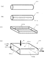
- FIG. 9 is a schematic diagram showing a manufacturing process of the elliptical cone-shaped light guide 20D.
- a cylindrical material for example, quartz glass
- FIG. 9A a cylindrical material (for example, quartz glass) is cut at side OA and side OB. That is, cutting is performed on a plane passing through point O, point O ′, and point A, and cutting is performed on a plane passing through point O, point O ′, and point B.
- FIG. 9 (B) parts such as the fragment OAB are removed.
- FIG. 9C the OA surface and the OB surface are bonded and cut along the CD surface.
- the light guide 20D is manufactured such that the entrance of the sunlight Sf is circular and the exit gradually becomes elliptical.
- this light guide 20D Since the exit (the output end of the laser medium) of this light guide 20D has an elliptical shape, light tends to gather on the plane side of the slab-shaped laser medium, and sunlight Sf incident on the laser medium increases. That is, the light guide structure is made to be an approximate elliptical cone so as to surround the slab-shaped laser medium, thereby increasing the absorption efficiency.
- the sunlight Sf collected by the Fresnel lens 10 has a circular shape at the incident portion. Since the light guide 20D is also substantially circular at the incident portion, the sunlight Sf can enter the light guide 20D smoothly. In the back of the light guide 20D, it becomes an approximate elliptical cone.
- the sunlight Sf is a laser as in the conical light guide 20 even in an elliptical cone shape. Collected toward the output end of the medium 31.
- the light guides 20B, 20C, and 20D have reflection surfaces 22B, 22C, and 22D that extend outward from the laser medium 31 from the output end of the laser medium 31, and reflect the sunlight Sf to the laser. Guide to medium 31.
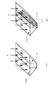
- FIG. 10 is a perspective view showing another modified example (wing-type light guide) of the light guide 20.
- FIG. 10A is a perspective view showing a wing type light guide used when the width of the laser medium is narrow and thick, and FIG. 10B shows the case where the width of the laser medium is wide and thin. It is a perspective view which shows the wing type light guide to be used.
- the prism-type light guide 20E uses a transparent optical material having substantially the same refractive index as that of the laser medium 31B.
- the laser medium 31B is YAG, undoped YAG crystal, ceramic YAG, or glass to which no light emitting element is added is used.
- the light guide 20E and the laser medium 31B are bonded by optical bonding or by an adhesive that has little absorption in the ultraviolet to near infrared wavelength region.
- ⁇ An antireflection film is deposited on the incident surface of the light guide 20E to prevent reflection loss and at the same time prevent corrosion due to guide water.
- excitation is performed from below the laser medium 31C using a reflecting mirror (wedge-shaped folding mirror) 27 as shown in FIG.
- This apparatus is very advantageous for exciting a laser medium using sunlight or a semiconductor laser having poor light collecting properties.
- FIG. 11 is a perspective view showing a modification of the laser medium 31.
- the laser medium 31 is a rod-type laser medium.
- the laser medium 41 is a grooved rod type laser medium.
- the laser medium 42 is a grooved slab type laser medium.
- the laser medium 45 is a wedged slab type laser medium.
- each laser medium has a rod-type laser medium 31, a slab-type laser medium, and a thermal effect (thermal lens, thermal birefringence, etc.) due to the excitation light of the laser medium.
- a grooved rod type laser medium 41, a grooved slab type laser medium 42, a wedged slab type laser medium 45, or the like may be used. These excitation methods are suitable for high-power laser oscillators because they have good cooling efficiency with the cooling water W.
- channel is a through-hole, ie, slit 41a, 42a, as shown in FIG.11 (B) and FIG.11 (C).
- the laser medium 41 has a slit 41a as an example of an opening extending in the optical axis direction of the laser medium.
- the width of the slit 41a of the laser medium 41 is approximately 1 mm.
- the laser medium 42 has a slit 42a as an example of an opening that is formed in a plate shape and extends in the optical axis direction of the laser medium.
- the laser medium 42 has a width of 25 to 30 mm, and the slit 42a has a width of about 1 mm.
- the laser oscillation device uses a grooved rod, a grooved slab, or a wedged slab laser medium to reduce the thermal lens effect or thermal birefringence of the laser medium due to absorption of sunlight. I have.
- the laser medium 41, 42 has an opening extending in the optical axis direction of the laser medium, and the area in contact with the cooling water increases, so that heat is easily radiated from the laser medium.
- thermal destruction, thermal birefringence, thermal lens effect, etc. can be reduced, and parasitic (parasitic) oscillation can be prevented. Therefore, the laser media 41 and 42 are suitable for high output.
- the slits 41a and 42a since the cooling water flows through the slits 41a and 42a, it is possible to efficiently prevent the temperature of the laser medium from rising. Further, since the laser medium 45 has a wedge portion, the surface area increases and heat is easily released.
- the laser medium 42 is formed in a plate shape, when the light guide 20C or the approximate elliptical cone-shaped light guide 20D is installed so as to surround the laser medium 42, it is reflected by the reflection surfaces 22C and 22D once or twice. Approximately 50% or more of the emitted sunlight is incident on the laser medium 42 and contributes to laser oscillation. Therefore, uniform excitation is possible, and the laser medium 42 is suitable for high output.
- the laser medium 42 has a slit 42a as an example of an opening extending in the optical axis direction of the laser medium, it oscillates in a straight optical path instead of zigzag. Therefore, optical axis adjustment (alignment) becomes easy.
- the laser beam is formed in the resonator, mixing of the adjacent laser beams across the slit 42a occurs, and it is considered that coherent oscillation can be obtained. It is also possible to arrange a plurality of laser media and increase the output of the laser, but it is extremely difficult to adjust so as to obtain coherent oscillation.
- FIG. 12 is a schematic diagram showing a schematic configuration example of the light guide and the laser medium in the present embodiment.
- the laser cavity including the light guide 20 shown in FIG. 12 is a laser cavity of the axial direction and side surface excitation device, and sunlight is incident from the axial direction to excite both the axial direction Sa and the side surface excitation Ss.
- This excitation method is suitable for a low-power laser oscillator.
- FIG. 13 is a diagram showing the laser output characteristics of this example.
- FIG. 14 is an explanatory diagram showing a performance comparison between the present embodiment and the prior art.
- the Fresnel lens 10 a plastic lens having a size of 1400 ⁇ 1050 mm and a focal length of 1.2 m was used.
- the laser guide and the laser medium are of a bi-directional excitation method of axial and side excitation.
- the laser medium 31 has a size of 9 ⁇ ⁇ 100 lmm (diameter 9 mm, length 100 mm), uses a YAG rod to which Nd and Cr are added, a high-reflection film on the incident-side rod surface, and an anti-reflection film on the output surface. Vapor deposited.
- the reflectance and the radius of curvature of the reflecting mirror (output mirror) on the output side were variable, and the reflectance and the radius of curvature of the reflecting mirror capable of obtaining the maximum output were obtained through experiments.
- FIG. 13 is a diagram showing laser output characteristics (marked by ⁇ ) when light is condensed by a Fresnel lens of 1400 mm ⁇ 1050 mm.
- a laser output of 24.4 W could be achieved by the sunlight input of 868 W.
- the output side reflecting mirror had a reflectance of 95% and a curvature radius of 38 cm.
- the excitation efficiency (laser output / sunlight input) reached 2.8%, and the best results were obtained as the data published so far.
- the Fresnel lens 10 is made of plastic, and four fan-shaped quarter-divided dimensions 1mx1m are shown in FIG. Experiments were performed using a 2 mx 2 m lens with a focal length of 2 m.
- FIG. 13 is a diagram showing a laser output characteristic (marked by a triangle) when focused by a Fresnel lens of 2000 ⁇ 2000 mm.
- a 79 W laser output was achieved by 1835 W sunlight input.
- the reflectance of the output side reflecting mirror was 95%, and the radius of curvature was 300 cm.
- the excitation efficiency (laser output / sunlight input) reached 4.3%, and the highest efficiency and maximum output were achieved as data published so far.
- the present invention has proven that laser oscillation using sunlight is very promising.
- FIG. 14 shows a comparison of the laser output per solar condensing area of various solar excitation lasers reported so far.
- the larger the laser power output for the area where sunlight is collected the higher the system utilization efficiency, and this index is important.
- the area utilization efficiency of the apparatus is improved by about 3 to 10 times, which shows the effectiveness of the present invention.
- FIG. 15 is a schematic diagram showing a schematic configuration example of a laser oscillation apparatus according to the second embodiment of the present invention.
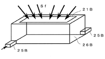
- FIG. 16 is a schematic view showing the laser housing of FIG.
- a solar-excited laser oscillation device (laser oscillator) 2 includes a Fresnel lens 10 that collects sunlight S, a light guide 20B that guides the collected sunlight to a laser cavity with high efficiency, and It is constituted by a laser cavity 30B.
- the laser cavity 30 ⁇ / b> B includes a high-reflection mirror 32 ⁇ / b> B, an output mirror 35 ⁇ / b> B, and a laser medium 42 housed in the laser housing 25.
- FIG. 16 is a schematic view showing a laser housing constituting the laser cavity.
- Sunlight from the light guide 20B is guided to the laser housing 25B through the sunlight incident window 21B, and excites the laser medium in the laser housing 25B.
- the laser medium is cooled with cooled pure water (temperature: 18 to 26 ° C.).
- a high reflector such as an aluminum metal or a metal reflector
- a scatterer with low absorption is used on the inner surface of the laser housing 25B.
- the laser medium attached to the laser housing 25B is excited from the side.
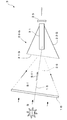
- FIG. 17 is a schematic diagram showing a schematic configuration example of a laser oscillation apparatus according to the third embodiment of the present invention.
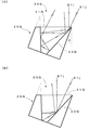
- FIG. 18 is a schematic diagram showing an optical path in the light guide.
- FIG. 18A shows an optical path of sunlight reflected near the end face of the reflecting surface 22G.
- FIG. 18B shows an optical path of sunlight reflected inside the reflecting surface 22G.
- the laser oscillation device 3 is different from the first embodiment in that the light guide 20G and the optical axis 16 of the Fresnel lens 10 are arranged obliquely with respect to the optical axis 36 of the laser medium 31. .
- the light guide 20G has a sunlight incident window 21G perpendicular to the optical axis 16 of the Fresnel lens 10 and a reflection surface 22G, as shown in FIGS.
- the light guide 20G has a shape obtained by cutting the light guide 20 along the plane of the sunlight incident window 21G.
- the reflection surface 22G has a reflection surface 22G with the optical axis 36 of the laser medium 31 at an angle ⁇ , that is, the light guide 20G tilted with respect to the optical axis 16 of the Fresnel lens 10.
- the inclination angle ⁇ is 15 ° to 25 °, and is 19.6 °, for example, in FIG.
- the normal incident light Sf1 incident on the vicinity of the end of the reflecting surface 22G of the light guide 20G is reflected several times on the upper part of the light guide 20G and then returns to the incident direction.
- the obliquely incident light Sf2 incident near the end of the reflecting surface 22G of the light guide 20G once reaches the back of the light guide 20G is reflected several times, and then returns to the incident direction.
- the sunlight Sf1 and Sf2 incident near the center of the entrance of the light guide 20G are reflected by the wall surface (reflection surface 22G) of the light guide 20G and gather in the back of the light guide 20G.
- the light guide By tilting the light guide in this way, sunlight is incident obliquely with respect to the optical axis of the laser medium, so that it is difficult for sunlight to concentrate on the output end of the laser medium, and the laser medium can be excited uniformly.
- the conversion efficiency from sunlight to laser light can be further improved.
- the laser output can be enhanced (increased efficiency) by increasing the number of reflections. Therefore, it is possible to prevent thermal destruction of the laser medium, thermal birefringence, thermal lens, parasitic oscillation, and the like, so that it is possible to generate a high-quality laser beam with good condensing performance.
- the light guide 20D shown in FIG. 19 is a light guide for the laser medium 42 having a slab shape. Also in this case, when the optical axis of the laser medium 42 is tilted by the angle ⁇ with respect to the optical axis of the Fresnel lens, a result similar to FIG. 18 was obtained.
- FIG. 20 is a schematic diagram showing the relationship between the optical path of FIG. 19 and the laser medium. As shown in FIG. 20, the laser medium 42 can be uniformly excited as the sunlight hardly concentrates at the output end of the laser medium 42. It turns out that it is.
- FIG. 21 is a schematic diagram showing an optical path in a modification of the light guide of FIG.
- the light guide 20H is installed in a state where the optical axis 36 of the laser medium 31 is inclined at an angle ⁇ (eg, 19.6 °) with respect to the optical axis 16 of the Fresnel lens 10.
- the angle of the reflecting surface 24a and the reflecting surface 24b is different from 25H. That is, the angle between the outer wall of the laser housing 25H and the reflecting surfaces 24a and 24b is different from the angle ⁇ and angle ⁇ ( ⁇ ⁇ ), respectively, and is asymmetric.
- the sunlight that has entered the vicinity of the center of the entrance of the light guide 20H is reflected by the wall surfaces (reflection surfaces 24a and 24b) of the light guide 20H and gathers in the back of the light guide 20H. .
- the light incident near the end of the reflection surface of the light guide 20H is reflected several times on the light guide 20H and then returns to the incident direction. That is, the laser medium can be uniformly excited by tilting the light guide.
- the number of reflections of the vertical incident light Sf1 and the oblique incident light Sf2 perpendicular to the sunlight incident window 21H is also increased in the light guide 20H. . That is, the absorption of sunlight in the laser medium can be increased.
- the condensing means may be a glass lens or a concave reflecting mirror, and it is sufficient that sunlight is collected on the incident window of the light guide.
- the fluorescent substance added to the Fresnel lens 10 prevents deterioration of the plastic, which is the material of the Fresnel lens, by light in the ultraviolet wavelength region, and makes this ultraviolet light effective in the visible wavelength region. Any substance that can be converted into excitation light may be used.
- the material of the laser medium 31 is not limited to YAG (Y 3 Al 5 O 12 ) or GSGG (Gd 3 Ac 2 Al 3 O 12 ) or the like in which Nd and Cr are added together as an example. Any material that can be absorbed widely can be used.
- the present invention is not limited to the above embodiments.
- Each of the embodiments described above is an exemplification, and any configuration that has substantially the same configuration as the technical idea described in the claims of the present invention and has the same operational effects can be used. It is included in the technical scope of the present invention.
- Laser oscillator 10 Fresnel lens 16: Fresnel lens optical axes 20, 20B, 20C, 20D, 20E: Light guide 21, 21B: Sunlight incident window (incident window) 22, 22B, 22C, 22D: reflecting surface 30: laser cavity 31, 41, 42, 45: laser medium 35: output mirror 36: optical axis 41a, 42a of laser medium: slit (opening) S, Sf: Sunlight
Landscapes
- Physics & Mathematics (AREA)
- Electromagnetism (AREA)
- Engineering & Computer Science (AREA)
- Plasma & Fusion (AREA)
- Optics & Photonics (AREA)
- Lasers (AREA)
Abstract
Description
まず、本発明に係る第1実施形態に係るレーザー発振装置の概要構成および機能について、図1から図4を用いて説明する。
図10は、光ガイド20の他の変形例(ウイング型光ガイド)を示す斜視図である。図10(A)は、レーザー媒質の幅が狭く、厚さが厚い場合に用いるウイング型光ガイドを示す斜視図で図10(B)は、レーザー媒質の幅が広く、厚さが薄い場合に用いるウイング型光ガイドを示す斜視図である。
図11は、レーザー媒質31の変形例を示す斜視図である。図11(A)に示すように、レーザー媒質31は、ロッド型のレーザー媒質である。図11(B)に示すように、レーザー媒質41は、溝付きロッド型のレーザー媒質である。図11(C)に示すように、レーザー媒質42は、溝付きスラブ型のレーザー媒質である。図11(D)に示すように、レーザー媒質45は、楔付きスラブ型のレーザー媒質である。
次に、本発明の第2実施形態に係るレーザー発振装置について説明する。
まず、第2実施形態に係るレーザー発振装置の概要構成について、図に基づき説明する。なお、前記第1実施形態と同一または対応する部分には、同一の符号を用いて異なる構成および作用のみを説明する。その他の実施形態および変形例も同様とする。
次に、本発明の第3実施形態に係るレーザー発振装置について図に説明する。
図17に示すように、レーザー発振装置3は、光ガイド20Gと、フレネルレンズ10の光軸16が、レーザー媒質31の光軸36に対して斜めに配置される点が第1実施形態と異なる。
図19に示した光ガイド20Dは、スラブ形状のレーザー媒質42用の光ガイドである。この場合も、フレネルレンズの光軸に対して、レーザー媒質42の光軸を角度θ傾けると、図18と似たような結果を得られた。図20は、図19の光路とレーザー媒質との関連を示す模式図であり、図20に示すように、レーザー媒質42の出力端部に太陽光が集中しにくくレーザー媒質42を均一に励起可能であることが分かる。
また、レーザー媒質31の材質は、例示したNdとCrを共添加したYAG(Y3Al5O12)やGSGG(Gd3Ac2Al3O12)等に限らず、太陽光のスペクトル成分を幅広く吸収できる材質であればよい。
10:フレネルレンズ
16:フレネルレンズの光軸
20、20B、20C、20D、20E:光ガイド
21、21B:太陽光入射窓(入射窓)
22、22B、22C、22D:反射面
30:レーザーキャビティ
31、41、42,45:レーザー媒質
35:出力ミラー
36:レーザー媒質の光軸
41a、42a:スリット(開口部)
S、Sf:太陽光
Claims (12)
- 太陽光により励起されてレーザー光を出力するレーザー媒質と、
前記レーザー媒質の出力端部に対向する凹面を有する出力ミラーと、
前記レーザー媒質の出力端部から、前記レーザー媒質の外方に延びる反射面を有し、前記太陽光を反射して前記レーザー媒質に導く光ガイドと、
を備えたことを特徴とするレーザー発振装置。 - 請求項1に記載のレーザー発振装置において、
前記光ガイドの反射面が、錐面であることを特徴とするレーザー発振装置。 - 請求項1または請求項2に記載のレーザー発振装置において、
前記レーザー媒質が、前記レーザー媒質の光軸方向に延びる開口部を有することを特徴とするレーザー発振装置。 - 請求項1から請求項3のいずれか1項に記載のレーザー発振装置において、
前記太陽光を集光して前記光ガイドに入射させる集光手段を更に備えたことを特徴とするレーザー発振装置。 - 請求項4項に記載のレーザー発振装置において、
前記集光手段の光軸が、前記レーザー媒質の光軸に対して斜めに配置されることを特徴とするレーザー発振装置。 - 請求項5に記載のレーザー発振装置において、
前記太陽光を取り入れる前記光ガイドの入射窓の面が、前記集光手段の光軸と垂直に配置されることを特徴とするレーザー発振装置。 - 請求項4から請求項6のいずれか1項に記載のレーザー発振装置において、
前記集光手段がフレネルレンズであって、
前記フレネルレンズに蛍光物質が添加されたことを特徴とするレーザー発振装置。 - 請求項7に記載のレーザー発振装置において、
前記フレネルレンズが、深紫外光によって表面改質されたことを特徴とするレーザー発振装置。 - 太陽光により励起されてレーザー光を出力するレーザー媒質を備え、
前記レーザー媒質が、前記レーザー媒質の光軸方向に延びる開口部を有することを特徴とするレーザー発振装置。 - 請求項9に記載のレーザー発振装置において、
前記開口部が、スリットを有することを特徴とするレーザー発振装置。 - 請求項9または請求項10に記載のレーザー発振装置において、
前記レーザー媒質が板状に形成されたことを特徴とするレーザー発振装置。 - 太陽光により励起されてレーザー光を出力するレーザー媒質と、
前記レーザー媒質の出力端部から、前記レーザー媒質の外方に延びる反射面を有し、前記太陽光を反射して前記レーザー媒質に導く光ガイドと、
前記太陽光を集光して前記光ガイドに入射させる集光手段と、
を備え、
前記集光手段の光軸が、前記レーザー媒質の光軸に対して斜めに配置されることを特徴とするレーザー発振装置。
Priority Applications (6)
| Application Number | Priority Date | Filing Date | Title |
|---|---|---|---|
| JP2010508246A JPWO2009128510A1 (ja) | 2008-04-17 | 2009-04-16 | レーザー発振装置 |
| CN2009801234121A CN102067394A (zh) | 2008-04-17 | 2009-04-16 | 激光振荡装置 |
| KR1020107025462A KR101188897B1 (ko) | 2008-04-17 | 2009-04-16 | 레이저 발진장치 |
| EP09733460A EP2273629A1 (en) | 2008-04-17 | 2009-04-16 | Laser oscillator |
| US12/988,495 US20110110389A1 (en) | 2008-04-17 | 2009-04-16 | Laser Oscillator |
| AU2009236901A AU2009236901A1 (en) | 2008-04-17 | 2009-04-16 | Laser oscillator |
Applications Claiming Priority (2)
| Application Number | Priority Date | Filing Date | Title |
|---|---|---|---|
| JP2008107782A JP2011023377A (ja) | 2008-04-17 | 2008-04-17 | 太陽光励起のレーザー発振装置 |
| JP2008-107782 | 2008-04-17 |
Publications (1)
| Publication Number | Publication Date |
|---|---|
| WO2009128510A1 true WO2009128510A1 (ja) | 2009-10-22 |
Family
ID=41199197
Family Applications (1)
| Application Number | Title | Priority Date | Filing Date |
|---|---|---|---|
| PCT/JP2009/057671 Ceased WO2009128510A1 (ja) | 2008-04-17 | 2009-04-16 | レーザー発振装置 |
Country Status (8)
| Country | Link |
|---|---|
| US (1) | US20110110389A1 (ja) |
| EP (1) | EP2273629A1 (ja) |
| JP (2) | JP2011023377A (ja) |
| KR (1) | KR101188897B1 (ja) |
| CN (1) | CN102067394A (ja) |
| AU (1) | AU2009236901A1 (ja) |
| TR (1) | TR201008488T1 (ja) |
| WO (1) | WO2009128510A1 (ja) |
Cited By (7)
| Publication number | Priority date | Publication date | Assignee | Title |
|---|---|---|---|---|
| JP2012072917A (ja) * | 2010-09-27 | 2012-04-12 | Denso Corp | 集光器及び集光装置 |
| KR101142848B1 (ko) | 2010-07-27 | 2012-05-08 | 제주대학교 산학협력단 | 소형 반사경과 광화이버를 이용한 열음향 레이져 장치 |
| JP2012134497A (ja) * | 2010-12-17 | 2012-07-12 | Thales | レーザービームを放射するための軸方向冷却を伴う反横断レーザー発振装置 |
| KR101207380B1 (ko) | 2011-07-27 | 2012-12-04 | 제주대학교 산학협력단 | 태양광을 이용한 고주파 열음향파 발생장치 |
| WO2013051354A1 (ja) * | 2011-10-07 | 2013-04-11 | 旭硝子株式会社 | 太陽光励起レーザー装置、太陽光励起増幅装置および光増幅ガラス |
| JP2013235930A (ja) * | 2012-05-08 | 2013-11-21 | Yabe Science Promotion Llc | 太陽光励起レーザー発振装置 |
| CN119726344A (zh) * | 2024-12-18 | 2025-03-28 | 苏州科技大学 | 激光系统及装置 |
Families Citing this family (7)
| Publication number | Priority date | Publication date | Assignee | Title |
|---|---|---|---|---|
| ES2396109B1 (es) * | 2011-07-05 | 2013-12-27 | Abengoa Solar New Technologies, S.A. | Dispositivo para la transformación de energía solar concentrada. |
| ES2396103B1 (es) * | 2011-07-05 | 2014-01-30 | Abengoa Solar New Technologies, S.A. | Planta solar. |
| CN103633536B (zh) * | 2012-08-20 | 2017-04-19 | 福州高意通讯有限公司 | 一种被动调q激光器 |
| CN103500914A (zh) * | 2013-09-02 | 2014-01-08 | 长春理工大学 | 一种太阳光泵浦激光器 |
| JP6497344B2 (ja) * | 2016-03-16 | 2019-04-10 | トヨタ自動車株式会社 | 太陽光励起レーザー装置 |
| JP6610513B2 (ja) | 2016-11-21 | 2019-11-27 | トヨタ自動車株式会社 | 太陽光励起ファイバーレーザー装置 |
| CN108613412A (zh) * | 2017-02-05 | 2018-10-02 | 鞍钢股份有限公司 | 一种太阳能诱发激光装置及方法 |
Citations (8)
| Publication number | Priority date | Publication date | Assignee | Title |
|---|---|---|---|---|
| JPS62234386A (ja) * | 1985-12-28 | 1987-10-14 | カ−ル・ツワイス・ステイフツング | 固体レ−ザ発振器 |
| JPH02303082A (ja) * | 1989-05-17 | 1990-12-17 | Takashi Mori | 光発振器 |
| JPH0563263A (ja) * | 1991-08-30 | 1993-03-12 | Hoya Corp | 半導体レーザ励起固体レーザ装置 |
| JPH11511592A (ja) * | 1995-08-28 | 1999-10-05 | ミネソタ マイニング アンド マニュファクチャリング カンパニー | 持続性のある蛍光ソーラコレクタ |
| JP2002033537A (ja) * | 2000-07-17 | 2002-01-31 | Laser Gijutsu Sogo Kenkyusho | 太陽光励起固体レーザ発生装置及びこれを用いた太陽光エネルギの輸送システム |
| JP2002088178A (ja) * | 2000-09-18 | 2002-03-27 | Seiko Epson Corp | 透明プラスチック部材の表面改質方法および表面改質装置、透明プラスチック部材の製造方法 |
| JP2003188441A (ja) | 2001-12-13 | 2003-07-04 | Ishikawajima Harima Heavy Ind Co Ltd | 太陽光直接励起レーザー発振装置 |
| JP2008066368A (ja) * | 2006-09-05 | 2008-03-21 | Okamoto Kogaku Kakosho:Kk | 太陽光励起レーザー装置 |
Family Cites Families (5)
| Publication number | Priority date | Publication date | Assignee | Title |
|---|---|---|---|---|
| US3297958A (en) * | 1963-01-23 | 1967-01-10 | Weiner Melvin | Solar pumped laser |
| US3784929A (en) * | 1972-10-30 | 1974-01-08 | Rca Corp | Thermally-controlled crystalline lasers |
| US4424592A (en) * | 1981-12-04 | 1984-01-03 | The United States Of America As Represented By The Administrator Of The National Aeronautics And Space Administration | Solar pumped laser |
| JP2003012569A (ja) * | 2001-06-28 | 2003-01-15 | Laser Gijutsu Sogo Kenkyusho | メタン又はメタノール生成システム |
| JP2009066368A (ja) | 2007-09-11 | 2009-04-02 | Ritsuko Shimoda | 簡単に編めて失敗しないための手作り布草履の芯 |
-
2008
- 2008-04-17 JP JP2008107782A patent/JP2011023377A/ja active Pending
-
2009
- 2009-04-16 JP JP2010508246A patent/JPWO2009128510A1/ja active Pending
- 2009-04-16 CN CN2009801234121A patent/CN102067394A/zh active Pending
- 2009-04-16 EP EP09733460A patent/EP2273629A1/en not_active Withdrawn
- 2009-04-16 AU AU2009236901A patent/AU2009236901A1/en not_active Abandoned
- 2009-04-16 WO PCT/JP2009/057671 patent/WO2009128510A1/ja not_active Ceased
- 2009-04-16 KR KR1020107025462A patent/KR101188897B1/ko not_active Expired - Fee Related
- 2009-04-16 US US12/988,495 patent/US20110110389A1/en not_active Abandoned
- 2009-04-16 TR TR2010/08488T patent/TR201008488T1/xx unknown
Patent Citations (8)
| Publication number | Priority date | Publication date | Assignee | Title |
|---|---|---|---|---|
| JPS62234386A (ja) * | 1985-12-28 | 1987-10-14 | カ−ル・ツワイス・ステイフツング | 固体レ−ザ発振器 |
| JPH02303082A (ja) * | 1989-05-17 | 1990-12-17 | Takashi Mori | 光発振器 |
| JPH0563263A (ja) * | 1991-08-30 | 1993-03-12 | Hoya Corp | 半導体レーザ励起固体レーザ装置 |
| JPH11511592A (ja) * | 1995-08-28 | 1999-10-05 | ミネソタ マイニング アンド マニュファクチャリング カンパニー | 持続性のある蛍光ソーラコレクタ |
| JP2002033537A (ja) * | 2000-07-17 | 2002-01-31 | Laser Gijutsu Sogo Kenkyusho | 太陽光励起固体レーザ発生装置及びこれを用いた太陽光エネルギの輸送システム |
| JP2002088178A (ja) * | 2000-09-18 | 2002-03-27 | Seiko Epson Corp | 透明プラスチック部材の表面改質方法および表面改質装置、透明プラスチック部材の製造方法 |
| JP2003188441A (ja) | 2001-12-13 | 2003-07-04 | Ishikawajima Harima Heavy Ind Co Ltd | 太陽光直接励起レーザー発振装置 |
| JP2008066368A (ja) * | 2006-09-05 | 2008-03-21 | Okamoto Kogaku Kakosho:Kk | 太陽光励起レーザー装置 |
Cited By (8)
| Publication number | Priority date | Publication date | Assignee | Title |
|---|---|---|---|---|
| KR101142848B1 (ko) | 2010-07-27 | 2012-05-08 | 제주대학교 산학협력단 | 소형 반사경과 광화이버를 이용한 열음향 레이져 장치 |
| JP2012072917A (ja) * | 2010-09-27 | 2012-04-12 | Denso Corp | 集光器及び集光装置 |
| JP2012134497A (ja) * | 2010-12-17 | 2012-07-12 | Thales | レーザービームを放射するための軸方向冷却を伴う反横断レーザー発振装置 |
| KR101207380B1 (ko) | 2011-07-27 | 2012-12-04 | 제주대학교 산학협력단 | 태양광을 이용한 고주파 열음향파 발생장치 |
| WO2013051354A1 (ja) * | 2011-10-07 | 2013-04-11 | 旭硝子株式会社 | 太陽光励起レーザー装置、太陽光励起増幅装置および光増幅ガラス |
| JPWO2013051354A1 (ja) * | 2011-10-07 | 2015-03-30 | 旭硝子株式会社 | 太陽光励起レーザー装置、太陽光励起増幅装置および光増幅ガラス |
| JP2013235930A (ja) * | 2012-05-08 | 2013-11-21 | Yabe Science Promotion Llc | 太陽光励起レーザー発振装置 |
| CN119726344A (zh) * | 2024-12-18 | 2025-03-28 | 苏州科技大学 | 激光系统及装置 |
Also Published As
| Publication number | Publication date |
|---|---|
| KR20110009147A (ko) | 2011-01-27 |
| US20110110389A1 (en) | 2011-05-12 |
| EP2273629A1 (en) | 2011-01-12 |
| CN102067394A (zh) | 2011-05-18 |
| AU2009236901A1 (en) | 2009-10-22 |
| TR201008488T1 (tr) | 2011-03-21 |
| KR101188897B1 (ko) | 2012-10-08 |
| JP2011023377A (ja) | 2011-02-03 |
| JPWO2009128510A1 (ja) | 2011-08-04 |
Similar Documents
| Publication | Publication Date | Title |
|---|---|---|
| WO2009128510A1 (ja) | レーザー発振装置 | |
| JP7037731B2 (ja) | フォノンバンド端発光に基づく全固体大出力スラブレーザ | |
| CN114784606B (zh) | 拉盖尔高斯光束产生装置及方法 | |
| US20080273570A1 (en) | Optically Pumped Waveguide Laser With a Tapered Waveguide Section | |
| RU2013146435A (ru) | Дисковый лазер | |
| CN115084982A (zh) | 一种面向高峰值功率激光的板条激光放大增益模块 | |
| CN119050800B (zh) | 一种声子带边线偏振激光器 | |
| CN101442177A (zh) | 一种实现低泵浦功率密度及连续光泵浦激光器的方法 | |
| CN100452572C (zh) | 基于铒镱共掺双包层光纤的中红外高功率激光光源 | |
| JPH06350171A (ja) | 固体レーザ装置および積分球 | |
| Almeida et al. | Design of a high brightness solar-pumped laser by light-guides | |
| CN118899738A (zh) | 一种基于缺陷透镜的涡旋激光产生装置 | |
| CN100505441C (zh) | 激光源的有源元件和包括该有源元件的激光源 | |
| JP4792279B2 (ja) | 太陽光励起レーザー装置 | |
| CN103337787A (zh) | 太阳光泵浦半导体纳米线激光器 | |
| JP2013235930A (ja) | 太陽光励起レーザー発振装置 | |
| JP4867032B2 (ja) | 太陽光励起レーザー装置 | |
| JP2008283189A (ja) | 異方性レーザー結晶を利用したダイオードポンピングされたレーザー装置 | |
| CN201054460Y (zh) | 基于铒镱共掺双包层光纤的中红外高功率激光光源 | |
| JPH09270552A (ja) | 固体レーザ装置 | |
| CN109818252A (zh) | 横向泵浦激光器 | |
| JP2004281595A (ja) | 固体レーザ装置 | |
| Vatnik et al. | High-efficiency lasing and spectroscopy of domestic 1% Nd: YAG and 1% Ho: YAG ceramics | |
| CN121355681A (zh) | 一种太阳光直接泵浦板条激光器 | |
| JP2676920B2 (ja) | 半導体レーザ励起固体レーザ装置 |
Legal Events
| Date | Code | Title | Description |
|---|---|---|---|
| WWE | Wipo information: entry into national phase |
Ref document number: 200980123412.1 Country of ref document: CN |
|
| 121 | Ep: the epo has been informed by wipo that ep was designated in this application |
Ref document number: 09733460 Country of ref document: EP Kind code of ref document: A1 |
|
| WWE | Wipo information: entry into national phase |
Ref document number: 2010508246 Country of ref document: JP Ref document number: 2010/08488 Country of ref document: TR |
|
| NENP | Non-entry into the national phase |
Ref country code: DE |
|
| WWE | Wipo information: entry into national phase |
Ref document number: 2009236901 Country of ref document: AU |
|
| WWE | Wipo information: entry into national phase |
Ref document number: 7583/DELNP/2010 Country of ref document: IN |
|
| REEP | Request for entry into the european phase |
Ref document number: 2009733460 Country of ref document: EP |
|
| WWE | Wipo information: entry into national phase |
Ref document number: 2009733460 Country of ref document: EP |
|
| ENP | Entry into the national phase |
Ref document number: 20107025462 Country of ref document: KR Kind code of ref document: A |
|
| ENP | Entry into the national phase |
Ref document number: 2009236901 Country of ref document: AU Date of ref document: 20090416 Kind code of ref document: A |
|
| WWE | Wipo information: entry into national phase |
Ref document number: 12988495 Country of ref document: US |