WO2009128676A9 - Module d'ossature de cloison en plâtre et terre crue, ossature de cloison en plâtre et terre crue et ossature de sol en terre crue utilisant ledit module, et procédé de construction de cloison en plâtre et terre crue au moyen dudit module - Google Patents
Module d'ossature de cloison en plâtre et terre crue, ossature de cloison en plâtre et terre crue et ossature de sol en terre crue utilisant ledit module, et procédé de construction de cloison en plâtre et terre crue au moyen dudit module Download PDFInfo
- Publication number
- WO2009128676A9 WO2009128676A9 PCT/KR2009/002011 KR2009002011W WO2009128676A9 WO 2009128676 A9 WO2009128676 A9 WO 2009128676A9 KR 2009002011 W KR2009002011 W KR 2009002011W WO 2009128676 A9 WO2009128676 A9 WO 2009128676A9
- Authority
- WO
- WIPO (PCT)
- Prior art keywords
- soil wall
- wall frame
- wire
- soil
- reinforcing
- Prior art date
- Legal status (The legal status is an assumption and is not a legal conclusion. Google has not performed a legal analysis and makes no representation as to the accuracy of the status listed.)
- Ceased
Links
Images


Classifications
-
- E—FIXED CONSTRUCTIONS
- E04—BUILDING
- E04B—GENERAL BUILDING CONSTRUCTIONS; WALLS, e.g. PARTITIONS; ROOFS; FLOORS; CEILINGS; INSULATION OR OTHER PROTECTION OF BUILDINGS
- E04B2/00—Walls, e.g. partitions, for buildings; Wall construction with regard to insulation; Connections specially adapted to walls
- E04B2/84—Walls made by casting, pouring, or tamping in situ
- E04B2/842—Walls made by casting, pouring, or tamping in situ by projecting or otherwise applying hardenable masses to the exterior of a form leaf
- E04B2/845—Walls made by casting, pouring, or tamping in situ by projecting or otherwise applying hardenable masses to the exterior of a form leaf the form leaf comprising a wire netting, lattice or the like
-
- E—FIXED CONSTRUCTIONS
- E02—HYDRAULIC ENGINEERING; FOUNDATIONS; SOIL SHIFTING
- E02D—FOUNDATIONS; EXCAVATIONS; EMBANKMENTS; UNDERGROUND OR UNDERWATER STRUCTURES
- E02D29/00—Independent underground or underwater structures; Retaining walls
- E02D29/02—Retaining or protecting walls
- E02D29/0208—Gabions
Definitions
- the present invention relates to a soil wall frame module used for constructing a soil wall, an earth wall frame formed using the soil wall frame module, and a method of constructing a soil wall.
- Soil construction refers to a construction method in which the main part of the wall of the building is constructed using soil. Soil construction is not only beneficial to the human body because it uses materials as it is, but because of the nature of the soil, the soil structure has excellent temperature and humidity control capabilities, and has the advantage of having proper insulation effect according to the outside temperature. . In addition, it is eco-friendly because it can reduce the carbon dioxide emissions generated in the concrete manufacturing process, and does not pollute the environment during the manufacturing process or disposal, and does not require a separate manufacturing process, it is also excellent in economic efficiency.
- Representative methods for building using soil include compaction and earth bricks.
- the compaction method uses a wooden formwork to fill the formwork with soil, and the ball is compacted with a light to build a wall.
- the wall constructed by this compacting method can exhibit considerable strength and durability if it can be compactly compacted.
- the construction method using the soil brick is a method of constructing walls by stacking soil bricks manufactured in various ways, and in spite of various advantages of the soil brick, a separate step of manufacturing the soil brick is required. to be.
- the present invention overcomes the disadvantages of the conventional soil wall construction method described above, it is possible to easily build a soil wall at a minimum cost, it is an object of the present invention to provide a soil wall frame so that the built wall has a sufficient durability to be.
- a soil wall frame module for constructing a soil wall the plurality of first transverse wires and a plurality of crosses attached to the first transverse wire cross the first transverse wire
- a first grating comprising a first longitudinal wire
- a second grating network comprising a plurality of second longitudinal wires and a plurality of second longitudinal wires attached to the second transverse wires by crossing the second transverse wires and the second transverse wires.
- Two grid nets are spaced apart at predetermined intervals.
- the soil wall frame module according to the present invention, a plurality of widthwise reinforcing steel wires both ends are respectively coupled to the first grid and the second grid; And a plurality of longitudinal reinforcing wires attached to the width reinforcing wires by crossing the widthwise reinforcing wires.
- the reinforcing grating is preferably coupled to the first grating and the second grating so as to be rotatable, respectively.
- a detachable clip having a first slot into which one of a pair of wires to be attached is fitted and a second slot into which the other is inserted are further formed. It may include.
- the soil wall frame according to the present invention is formed by connecting at least one soil wall frame module according to the present invention in the transverse direction, the longitudinal direction and the width direction.
- the first grid network installation step of installing a first grid network formed by crossing a plurality of first transverse wires and a plurality of first longitudinal wires to each other on the base to build the soil wall ;
- a second grating network installation step of installing a second grating network formed by crossing a plurality of second transverse wires and a plurality of second longitudinal wires apart from the first grating network at predetermined intervals;
- a filling step of applying and filling the earth filler between the first grid and the second grid.
- the soil wall frame is configured using the soil wall frame module of the present invention
- the soil is applied in the form of a mixture mixed with water, but it is difficult to discuss the structural strength by itself so that the clay dough can be considered amorphous, but as the clay dough is constrained by the soil wall frame module, the soil wall frame module Interactions with them result in unexpectedly high structural strength.
- the earthen dough to the soil wall frame module according to the present invention can be filled with the earth wall to a height of more than a typical two-story building.
- the soil wall frame of the present invention is manufactured using a thin wire, not only can reduce the production cost, but also minimizes the volume occupied in the soil wall and maximizes the ratio of soil, thereby maximizing the effect of the soil wall. have.
- the earthen dough filled in the soil wall frame module is not supported by the reinforcing grid between the first grid and the second grid, it is possible to build the earth wall more easily.
- the reinforcing grating according to the present invention which is made of thin steel wire, can support the first grating and the second grating with sufficient force, not only in the process of constructing the soil wall but also after the soil wall is constructed.
- the mold can be prevented from being deformed, and can withstand strong vibrations caused by earthquakes.
- the soil wall frame module of the present invention it is possible to easily adjust the height and thickness of the soil wall according to the loading method and the quantity, it is possible to build the soil wall with a plurality of soil by varying the type of soil to be applied. It is easy to insert a heat insulating material between the earth walls.
- the soil wall frame module is manufactured using a wire which is easily deformed in shape, a wall frame for constructing a circular or curved wall in addition to the rectangular wall can be easily manufactured.
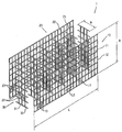
- FIG. 1 is an exploded perspective view showing a soil wall frame module according to the present invention.
- Figure 2 is a perspective view showing a state installed on the soil wall frame module according to FIG.
- FIG. 3 is a perspective view showing a soil wall frame according to the present invention produced using the soil wall frame module of FIG.
- FIG. 4 is a front perspective view showing that the intermediate material is inserted between the soil wall frame of FIG.
- FIG. 5 is a front perspective view illustrating that different earth dough is applied to the divided wall mold by inserting the barrier material between the soil wall mold of FIG. 3.
- Figure 6 is a view showing another embodiment of the soil wall frame module and soil wall frame of the present invention.
- FIG. 7 is a perspective view showing a soil wall frame provided with a panel for plastering according to the present invention.
- FIG. 8 is an explanatory diagram showing the construction of a soil ball frame using the soil wall frame module according to FIG. 1;
- FIG. 9 is a partially enlarged perspective view illustrating a coupling structure of a first grid and a reinforcement grid of the soil wall frame module according to FIG. 1;
- FIG. 10 is a partially enlarged perspective view illustrating another use state of the embodiment of FIG. 9;
- FIG. 11 is an exploded perspective view of another embodiment of a soil wall frame module according to the present invention.
- FIG. 12 is a perspective view of one embodiment of a detachable clip of a soil wall frame module according to the present invention.
- FIG. 13 is a perspective view of a state of use of the removable clip of FIG.
- FIG. 14 is a perspective view of another embodiment of a detachable clip of a soil wall frame module according to the present invention.
- FIG. 15 is a perspective view of a state of use of the removable clip of FIG.
- FIG. 16 is a perspective view of another embodiment of a detachable clip of a soil wall frame module according to the present invention.
- FIG. 17 is a perspective view from another direction of another embodiment of a detachable clip of a soil wall frame module according to the present invention.
- FIG. 18 is a perspective view of a use state of the removable clip of FIG.
- the soil wall frame module 1 is an exploded perspective view showing a soil wall frame module 1 according to the present invention.
- the soil wall frame module 1 has a configuration in which the first grid 10 and the second grid 20 are spaced apart at predetermined intervals, and the first grid 10 and the second grid are arranged. 20 is preferably coupled with the reinforcing grid 30 in between.
- the first grating network 10 includes a plurality of first transverse wires 11 arranged at predetermined intervals L1 and a plurality of first longitudinal wires 12 arranged at predetermined intervals L2. )
- the first transverse iron wire 11 and the first longitudinal iron wire 12 are attached to each other in a state in which they are arranged in a lattice form while crossing each other.
- the distance L1 between the first transverse wire 11 and the distance L2 between the first longitudinal wire 12 vary depending on the viscosity of the soil to be applied, but are generally preferably 40 to 50 mm each. .
- the second grating network 20 is spaced apart from the first grating network 10 at a predetermined interval, and the plurality of second transverse wires 21 and the same as the configuration of the first grating network 10 and The second longitudinal iron wire 22 is comprised.
- the second transverse wires 21 and the second longitudinal wires 22 are attached to each other in a state in which they are arranged in a lattice shape to cross each other, and the spacing between the wires is also equal to that of the first grid network 10. It is formed similarly to the structure.
- the first grating network 10 and the second grating network 20 are arranged at predetermined intervals from each other, and this interval is preferably set to be equal to or greater than the minimum thickness of the wall to be constructed.
- the soil wall frame module 1 preferably includes a reinforcing grid 30 for coupling the first grid 10 and the second grid 20. Since the reinforcing grid 30 serves to hold the soil filled between the first grid 10 and the second grid 20 so as not to flow, the manpower and cost in the application of the soil is significantly reduced Brings the effect.
- the reinforcing grid 30 has a plurality of widthwise reinforcing wires 31 and a plurality of longitudinal reinforcing wires 32. Both ends of the widthwise reinforcing wire 31 are attached to predetermined positions of the first grid 10 and the second grid 20, respectively, the longitudinal reinforcing wire 32 is a plurality of width reinforcing wire 31 ) And extends toward ground (80).
- the widthwise reinforcing wire 31 and the longitudinal reinforcing wire 32 are preferably attached to each other.
- first transverse wire 11 and the first longitudinal wire 12 of the first grid 10 may be attached to each other by electric welding or oxygen welding such as resistance welding or arc welding.
- the soil wall frame module 1 according to the present invention is a welding device In a separate manufacturing place equipped with at least the first grid 10 or the second grid 20 or reinforcement grid 30 separately prepared in advance and transported to the construction site of the earthen building and then bonded to each other The finished product must be transported to the construction site after assembly.
- pre-fabrication after transport is not always advantageous, and in some cases it may be necessary to manufacture the soil wall frame module according to the present invention at the construction site of the soil building.
- the widthwise reinforcing wire 31 and the longitudinal reinforcing wire 32 of 30 may be arranged to cross each other, and then a pair of iron wires intersecting with each other may be fixed to each other by inserting a removable clip at the intersection.
- . 12 and 13 illustrate an example and use state of the detachable clip 510.
- the detachable clip 510 is substantially orthogonal to the first slot 511 and the first slot 511 to which one of the pair of wires intersecting each other, for example, the first transverse wire 11 is fitted, is mutually orthogonal to each other.
- the depth of each slot (511,512) will be determined according to the thickness of the wire, but since the second slot 512 should have a depth corresponding to the thickness of the two wires eventually should be deeper than the first slot (511).
- the detachable clip 510 of this type presses the detachable clip 510 at the intersection point in the state where the first transverse wire 11 and the first longitudinal wire 12 intersect so that the wire is fitted in each slot. It can be combined simply by doing.
- the first slot 511 and the second slot 512 may be formed crosswise on the same side of the detachable clip as shown in FIG.
- the second slot 522 has the side opposite to the one side on which the first slot 521 is formed ( In the figure, the upper surface is formed in an example).
- the second slot 521 and the first slot 521 may be arbitrarily determined depending on the thickness of the iron wire, and may have the same depth.
- a deformable form may be applied at the level of those skilled in the art, but any form of the first grid of the soil wall frame module according to the present invention may be applied to only the plurality of wires at the construction site of the soil building.
- the net 10, the second grating 20 and the reinforcing grating 30 can be manufactured directly.
- both ends of the width direction reinforcing wire 31 is rotatably coupled to the corresponding position of the first grating 10 and the second grating 20, respectively.
- FIG. 9 is an enlarged view of a portion where the reinforcing grating 30 and the first grating 10 contact with each other in the embodiment of FIG. 1, and FIG. 10 shows the reinforcing grating 30 and the first grating in FIG. 9. The state which inserted the fixing clip 25 in the part which 10 touches is illustrated.
- the widthwise reinforcing wire 31 of the reinforcing grid 30 has one end 31a formed in an annular shape so as to be connected to any one of the first longitudinal wires 12 of the first grid 10.
- any other form of coupling It may be a structure.
- one end 31a of the widthwise reinforcing wire 31 is illustrated in FIG. 9 in a simple ring shape, that is, the first longitudinal wire 12 is wound once, the first longitudinal wire 12 is illustrated. It may also be wound several times in order to prevent deviation from.
- the coupling of the reinforcing grating 30 and the second grating 20 is also made in the same way.
- the entire cube-shaped structure consisting of the first grating 10, the second grating 20 and the reinforcing grating 30 can be folded into a thin plate shape. Therefore, after preparing the soil wall frame module according to the present invention in advance, when transported to the construction site, it is possible to simply reduce the volume of the soil wall frame module. In addition, by arriving at the construction site by unfolding the folded soil wall frame module can be returned to the cube shape.
- a fixing clip 25 having a shape in which two sides 25a and 25b adjacent to a right angle are curved in a right-angled triangular plate, respectively. Is inserted into the widthwise reinforcing wire 31 of the reinforcing grating 30 and the first longitudinal wire 12 of the first grating 10, respectively.
- the state illustrated in FIG. 9 is a state in which the widthwise reinforcing wire 31, that is, the reinforcing grating 30 is free to rotate with respect to the first longitudinal wire 12, that is, the first grating 10.
- the state illustrated in FIG. 10 is a state in which such rotation is suppressed by the fixing clip 25.
- the fixing clip 25 is formed of a generally right-angled triangular plate, and the curved two sides 25a and 25b are also curved in the same direction, but the specific shape and the curved direction thereof are It may vary as needed.
- the detachable clips 510 and 520 described above may be modified to form a function of the fixing clip 25 as described above.
- the detachable clip 530 illustrated in FIG. 16 has basically the same characteristics as the detachable clips 510 and 520 illustrated in FIGS. 12 to 15, except that the detachable clip 530 includes a third slot 533. As illustrated in FIGS.
- the third slot 533 is formed in a direction crossing the first slot 531 and the second slot 532, respectively, and is formed to penetrate up and down based on the drawing direction.
- the first slot 531 is a groove formed in a direction parallel to the x axis in the xyz coordinate system
- the second slot 532 is a groove formed in a direction parallel to the y axis
- the third slot 533 is It is a groove formed in a direction parallel to the z axis.
- the depth of the third slot 533 that is, the depth measured while following the third slot 533 from the right open end to the left closed end in the direction of the drawing of FIG.
- the detachable clip 530 of this type has a pair of wires, such as the first transverse wire 11 and the first longitudinal direction, in the second slot 532 and the third slot 533, as shown in FIG. 18.
- the first reinforcing wire 31 of the reinforcing grid 30 in the widthwise reinforcing grid 31 is further inserted in the first slot 531, the first transverse wire 11 and the first longitudinal wire While fixing 12 to each other, it can also function as a fixing clip for fixing the reinforcing grid 30 to the first grid 10.
- the removable clip 530 can be regarded as a modification of the fixed clip.
- a through hole 530a is formed at one side of the detachable clip 530 to cross the third slot 533, and the fixing pin is formed in the through hole 530a.
- 540 may be inserted. As shown in FIG.
- the fixing pin 540 is inserted into and fixed to the through-hole 530a of the detachable clip 530 in a state where iron wires are inserted into each slot of the detachable clip 530.
- the first longitudinal wire 12 can be prevented from escaping from the three slots 533. In this way, it is not only the third slot 533, but also the first slot 531 and the second slot 532 that insert the fixing pin 540 into the open end side of any one slot to prevent the wire from being separated from the slot. The same can be applied to).
- first transverse wire 11 and the second transverse wire 21 are generally parallel to the ground 80, and the first longitudinal wire 12 and the second longitudinal wire ( 22 is shown installed in a direction orthogonal to the transverse wires 11 and 21, but the transverse wires 11 and 21 and the longitudinal wires 12 and 22 depending on the conditions in which the wall is constructed. It may be installed inclined with respect to the ground, or may be manufactured in various other ways.
- the widthwise reinforcing wire 31 and the longitudinal reinforcing wire 32 of the reinforcing grating 30 may also be installed in various ways in relation to the first grating 10 and the second grating 20. It is self-evident.
- the first grating 10 may further include a first oblique wire 13.
- the first oblique wire 13 is disposed in a direction crossing the first transverse wire 11 and the first longitudinal wire 12, respectively, the first transverse wire 11 or the first longitudinal wire ( 12) is attached.
- the first diagonal wire 13 is provided, not only the structural strength of the first grating 10 is increased, but also the soil is filled between the first grating 10 and the second grating 20 in the future In addition, the filled soil may pass through the grid of the first grid 10 to reduce overflow.
- the configuration of the first oblique wire 13 may be applied to the second oblique wire 23 in the second grid 20, the oblique reinforcing wire 33 in the reinforcement grid 30. .
- the thickness of the iron wires (11, 12, 21, 22, 31, 32) used in the soil wall frame module 1 of the present invention is appropriately depending on various conditions such as the thickness of the wall to be built, the viscosity of the soil, the place of construction You can change it and use it.
- the wires 11, 12, 21, 22, 31, The thickness of 32 is preferably about 3 to 10 mm depending on the construction conditions of the soil wall.
- the soil wall frame module (1) has a total height (H) between 500 to 3000 mm, the width (W) should be made of 100 to 1000 mm convenient to form the soil wall frame 100 as will be described later Do.
- the width W of the soil wall frame module itself may be 20 to 50 mm.
- the spacing of the first longitudinal wire and the first transverse wire, the second longitudinal wire and the second transverse wire is 15 to 30 mm, and each cross wire is preferably attached to each other by welding.
- FIG. 2 is a perspective view showing the installation of a single soil wall frame module 1 according to the present invention shown in FIG. 1 on the ground 80.
- a support structure 70 for supporting the soil wall frame module 1.
- Such a support structure 70 is particularly useful for supporting the soil wall frame module 1 in the case where the soil wall is added to the existing wall described above, but the strength of the soil wall frame module 1 alone is sufficient.
- the support structure 70 may be omitted.
- the supporting structure 70 is a pair of lateral supports 71 supporting the soil wall frame module 1 by laterally contacting each side surface of the first grid 10 and the second grid 20. 71 ').
- the transverse supports 71, 71 ' have a pair of transverse rims 72, 72', width rims 73, 73 'and longitudinal rims 74, 74', 74 '' as in FIG. , 74 '' ').
- FIG. 3 is a perspective view showing that the soil wall frame 100 according to the present invention is installed on the ground 80. 3 also shows a support structure 70 for supporting the soil wall frame 100.
- the soil wall frame 100 is formed by constructing one or more soil wall frame modules 1 according to the present invention shown in FIGS. 1 and 2. That is, the plurality of soil wall frame modules 1 are attached in the transverse direction, the longitudinal direction and the width direction, respectively, according to the length, height and width of the wall to be constructed, and the soil wall frame 100 according to a predetermined length, height and width. ). In FIG. 3, two soil wall frame modules 1 are attached to each other in the lateral direction, the longitudinal direction, and the width direction, respectively, to fabricate the soil wall frame 100. Thus, using the soil wall frame module 1 produced in a predetermined standard, it is possible to easily install the soil wall frame 100 for producing a wall having a desired length, height and width.
- a support structure 70 for supporting the outer surface of the soil wall frame 100 As shown in FIG. .
- the structure of the support structure 70 is the same as described above with reference to FIG.
- the soil wall frame 100 of the present invention is manufactured using a relatively thin iron wire (11, 12, 21, 22, 31, 32), it is also possible to cut a part of it using a general cutting device to remove it. It is easy. Therefore, as shown in FIG. 3, when an open area 110 is required in a part of the wall to be constructed, that is, when a window is provided or a door is to be formed, the present invention is not required to use a separate wall frame. After stacking the soil wall frame module (1) to produce a soil wall frame 100 can be easily opened by cutting out the portion of the window or door required.
- an intermediate material 50 may be inserted between the soil wall frame modules 1 forming the soil wall frame 100 according to a predetermined purpose.
- a gap having a width of about 30 to 150 mm, or more, is formed between both soil wall frame modules 1, so that the insulation material of the natural material, which is the intermediate material 50, and compression therebetween. Crests, sawdust, chopped crests, and / or woven reeds.
- each of the divided soil wall frame module (1) Other types of clay pastes 40 and 40 'may be applied or filled.
- a barrier 60 such as a wooden board (a thin thermal insulation material) between both soil wall frame modules 1, the lime wall module 1 on the outer wall side exposed to the external environment is quicklime.
- the clay dough mixed with cement and soil, and applying the ocher clay dough to the inner wall side wall module 1 on the inner wall to form a room the wall filled with different soil according to the function of the outer wall and the inner wall Can be constructed.
- the strength of the wall can be increased compared to the wall using only yellow soil, by the method of applying different clay dough to the soil wall frame 100 divided into a plurality of compartments, the higher-rise building than the existing building You can also build a.
- FIG. 6 illustrates an embodiment in which a circular wall 200 is constructed using the soil wall frame module 1 and the soil wall frame 100 of the present invention. Since the iron wires 11, 12, 21, 22, 31, and 32 forming the soil wall frame module 1 of the present invention are thin, the iron wires are freely deformed, as shown in FIGS. In addition to the wall frame in the long direction can be easily produced circular wall frame as shown in Figure 6, other curved wall frame can also be easily produced.
- FIG. 7 illustrates a configuration in which the present invention installs a separate plastering panel 90 in the soil wall frame 100 so as not to perform separate plastering when constructing the soil wall.
- Plastering panel 90 is attached to the mesh-like mesh 91 with fine particles on the inner surface.
- Plastering panel 90 to which the mesh net 91 is attached is installed in the soil wall frame 100 at intervals of a predetermined plastering thickness l, for example, 10 to 30 mm.
- the soil wall mold 100 is filled with the soil dough 40, and after the soil dough 40 is stabilized to some extent, the plastering panel 90 is used to promote drying of the soil dough. Should be removed.
- the mesh net 91 located between the plastering panel 90 and the soil wall frame 100 remains attached to the soil wall, so the plastering panel 90 is filled with the clay dough 40. It can be easily removed and removed from the soil wall frame (100). After removing the plastering panel 90, the earthen dough 90 is completely dried to remove the mesh-type net 91 to complete the construction of the earthen wall.
- the mesh net 91 may be left unremoved in some cases. For example, if the mesh 91 is of a material having a tensile strength sufficient to be able to function as a reinforcement against the soil wall, it may be advantageous to leave the soil dough 90 even after it has dried.
- the surface of the wall of the earth wall completed using the panel for plastering 90 is formed evenly, there is no need for separate plastering.
- a plurality of bolts 93 are fixed to the soil wall frame 100 and correspondingly bolted to the plastering panel 90
- the through hole 92 can be provided.
- the nut may be fixed to the soil wall frame 100 and the bolt may be inserted from the outside of the panel for plastering 90 to fix the panel for plastering 90, using a separate support structure 70 to plaster the plastering.
- the panel 90 may be fixed.
- By forming so that both ends of the widthwise reinforcing wire 31 of the reinforcing grid 30 to serve as the above-described bolt 93 may be fixed to the plastering panel 90 to the soil wall frame (100).
- Plastering panel 90 may be installed in the soil wall frame 100 using other methods.
- the earthen dough 40 is filled and then earthen dough 40 If this is stable to some extent, it may include the step of compressing the earthen dough 40 filled in the soil wall frame 100 by tightening the nut or bolt of the panel for plastering (90). According to this method, it is possible to increase the density of the constructed soil wall to prevent the cracking of the wall and to make the plaster more solid.
- the soil wall frame module 1 is installed on the ground 80, and the other soil wall frame module 1 is attached to the soil wall frame module 1 installed on the ground 80.
- the soil wall mold 100 is manufactured by repeating the process of attaching in the lateral direction, the longitudinal direction and / or the width direction, the soil dough 40 may be applied to the soil wall mold 100 to construct the soil wall.
- the support structure 70 may be installed to support and fix the soil wall frame 100.
- the soil wall according to the invention grounds the first grating network 10 formed by the plurality of first transverse wires 11 and the plurality of first longitudinal wires 12 intersecting and attached to each other.
- the second grid 20 is spaced apart from the first grid 10 at a predetermined interval in the same manner, and then the widthwise reinforcing wire 31 is installed.
- the reinforcing lattice network 30 having the longitudinal reinforcing steel wires 32 formed to cross each other between the first lattice network 10 and the second lattice network 20 to fabricate the soil wall frame 100.
- the earth dough 40 may be constructed by applying and filling the earth wall mold 100 between the first grid 10 and the second grid 20. In this case, while installing the support structure 70 to support and fix the soil wall frame 100, it is possible to manufacture the soil wall frame 100 and apply the soil dough (40).
- the soil wall frame 100 After manufacturing the soil wall frame 100, according to the design of the building to be built, if there is an open portion such as a window or a door in a part of the building cut the portion of the soil wall frame 100 corresponding thereto It can be pulled out to form the open area 110.
- an open portion such as a window or a door in a part of the building cut the portion of the soil wall frame 100 corresponding thereto It can be pulled out to form the open area 110.
- Plastering panel 90 is installed in the position, after removing the plastering panel 90 after filling the earthen dough 40 can be built without the need for a separate plastering soil wall.
- the mesh net 91 is attached to the inner side of the plaster panel 90, that is, the soil wall frame side, the mesh net 91 is used to remove the plaster panel 90 in the process of removing the plaster panel 90. It is separated from the 90 and remains on the soil wall.
- the step of removing the mesh-type mesh 91 remaining in the soil wall should be further included.
- this step can be omitted.
- the iron wire used in the present invention is more preferably used for the application of the earthen dough 40 using a deformed iron wire.
- a soil wall frame by combining a variety of iron wires of different thicknesses.
- the soil dough 40 used in the present invention can be used at the same time a variety of color of the earth dough, it is possible to build a soil wall of various colors and patterns.
- the soil wall frame module and the soil wall frame according to the present invention can be used not only to construct soil walls, but also to construct soil fences, soil signs, soil fireplaces and the like. In addition, it can be used to build not only walls but also floors (spheres) in earthen structures, and can be used to build ceilings. On the other hand, it is possible to produce a large earth brick having a thickness of 100mm ⁇ 1000mm using the soil wall frame module of the present invention, it is also possible to produce a 20mm ⁇ 90mm thick earth panel.
- the soil spheres in order to build the soil spheres 300, according to the size and shape of the spheres to be built the soil wall frame module 1 according to the present invention in the transverse direction, longitudinal direction And / or connected in the width direction to form a saddle frame 310, by filling the earthen dough into the saddle frame 310 can be built in the soil sphere (300).
- the built earthen spheres 300 may be laid with a boiler line 311 or the like, and after finishing the boiler line 311 may be finished by plastering.
Landscapes
- Engineering & Computer Science (AREA)
- Civil Engineering (AREA)
- Architecture (AREA)
- Structural Engineering (AREA)
- General Life Sciences & Earth Sciences (AREA)
- Paleontology (AREA)
- Mining & Mineral Resources (AREA)
- General Engineering & Computer Science (AREA)
- Life Sciences & Earth Sciences (AREA)
- Physics & Mathematics (AREA)
- Environmental & Geological Engineering (AREA)
- Electromagnetism (AREA)
- Pit Excavations, Shoring, Fill Or Stabilisation Of Slopes (AREA)
- Panels For Use In Building Construction (AREA)
Abstract
La présente invention concerne un module d'ossature de cloison en plâtre et terre crue permettant de construire une cloison en plâtre et terre crue. Le module présente un treillis primaire comprenant plusieurs fils d'acier horizontaux primaires et plusieurs fils d'acier verticaux qui croisent les fils d'acier horizontaux primaires et sont attachés à ceux-ci, ainsi qu'un treillis secondaire comprenant plusieurs fils d'acier horizontaux secondaires et plusieurs fils d'acier verticaux secondaires qui croisent les fils d'acier horizontaux secondaires et sont attachés à ceux-ci. Le treillis primaire et le treillis secondaire se trouvent à distance l'un de l'autre selon un certain intervalle. De plus, le module d'ossature de cloison en plâtre et terre crue comprend plusieurs fils d'acier de renfort transversal dont les deux extrémités sont respectivement reliées au treillis primaire et au treillis secondaire, ainsi que plusieurs fils d'acier de renfort vertical qui croisent les fils d'acier de renfort transversal et sont attachés à ceux-ci.
Applications Claiming Priority (4)
| Application Number | Priority Date | Filing Date | Title |
|---|---|---|---|
| KR10-2008-0036343 | 2008-04-18 | ||
| KR20080036343 | 2008-04-18 | ||
| KR10-2009-0031420 | 2009-04-10 | ||
| KR1020090031420A KR101003371B1 (ko) | 2008-04-18 | 2009-04-10 | 흙 벽체 틀 모듈 및 이를 이용한 흙 벽체 틀과 흙 구들 틀 그리고 이를 이용한 흙 벽체 축조 방법 |
Publications (3)
| Publication Number | Publication Date |
|---|---|
| WO2009128676A2 WO2009128676A2 (fr) | 2009-10-22 |
| WO2009128676A9 true WO2009128676A9 (fr) | 2009-12-17 |
| WO2009128676A3 WO2009128676A3 (fr) | 2010-02-04 |
Family
ID=41199592
Family Applications (1)
| Application Number | Title | Priority Date | Filing Date |
|---|---|---|---|
| PCT/KR2009/002011 Ceased WO2009128676A2 (fr) | 2008-04-18 | 2009-04-17 | Module d'ossature de cloison en plâtre et terre crue, ossature de cloison en plâtre et terre crue et ossature de sol en terre crue utilisant ledit module, et procédé de construction de cloison en plâtre et terre crue au moyen dudit module |
Country Status (1)
| Country | Link |
|---|---|
| WO (1) | WO2009128676A2 (fr) |
Families Citing this family (2)
| Publication number | Priority date | Publication date | Assignee | Title |
|---|---|---|---|---|
| CN103046665B (zh) * | 2012-12-14 | 2015-06-17 | 北京工业大学 | 设马牙构造柱带钢丝网保温砂浆强化层空斗墙及作法 |
| CN103485453B (zh) * | 2013-07-11 | 2015-07-15 | 刘洪元 | 一种现浇石膏墙施工方法 |
Family Cites Families (6)
| Publication number | Priority date | Publication date | Assignee | Title |
|---|---|---|---|---|
| KR830002608Y1 (ko) * | 1982-01-05 | 1983-12-07 | 전주한 | 거푸집 없는 콘트리트 벽체 |
| KR19990014402A (ko) * | 1998-11-05 | 1999-02-25 | 김용호 | 건축용 황토패널의 구조 |
| KR200275111Y1 (ko) * | 1999-05-19 | 2002-05-10 | 조홍준 | 철근간격유지용 월 스페이서 |
| KR20050007837A (ko) * | 2003-07-11 | 2005-01-21 | 두산중공업 주식회사 | 와이어메시를 이용한 콘크리트 문양벽체 및 콘크리트문양벽체 시공방법 |
| US6871471B1 (en) * | 2003-08-15 | 2005-03-29 | Tommy Davidson | Apparatus, and associated method, for securing rebar together |
| KR100831690B1 (ko) * | 2007-06-22 | 2008-05-22 | 박정진 | 철근 배근구조 |
-
2009
- 2009-04-17 WO PCT/KR2009/002011 patent/WO2009128676A2/fr not_active Ceased
Also Published As
| Publication number | Publication date |
|---|---|
| WO2009128676A2 (fr) | 2009-10-22 |
| WO2009128676A3 (fr) | 2010-02-04 |
Similar Documents
| Publication | Publication Date | Title |
|---|---|---|
| US7073306B1 (en) | Method of building | |
| KR101003371B1 (ko) | 흙 벽체 틀 모듈 및 이를 이용한 흙 벽체 틀과 흙 구들 틀 그리고 이를 이용한 흙 벽체 축조 방법 | |
| CN105971166A (zh) | 一种型钢骨架石膏板、新型免拆模板 | |
| CN201952966U (zh) | 承重结构和房屋结构 | |
| CN105672562A (zh) | 蒸压加气混凝土整体保温墙板及其生产工艺 | |
| KR100304861B1 (ko) | 건축용단열프리캐스트콘크리트판넬 | |
| CN201495626U (zh) | 一种柱网连锁框架建筑结构 | |
| CN112695950A (zh) | 一种新型装配式墙板、墙体结构及加工方法 | |
| CN106193389A (zh) | 一种免拆建筑模板组件 | |
| WO2009128676A9 (fr) | Module d'ossature de cloison en plâtre et terre crue, ossature de cloison en plâtre et terre crue et ossature de sol en terre crue utilisant ledit module, et procédé de construction de cloison en plâtre et terre crue au moyen dudit module | |
| CN109629732B (zh) | 一种管线分离的现浇混凝土隐形梁楼板及施工方法 | |
| CN109779033B (zh) | 一种装配式房屋及其施工方法 | |
| CN104533012B (zh) | 一种可承重轻质板材及其制作方法、组合墙板和房屋 | |
| CN113216678A (zh) | 既有建筑砌体承重墙加固结构及其施工方法 | |
| CN107299718A (zh) | 质轻节能环保的预制楼板及其安装工艺 | |
| CN216713563U (zh) | 一种新型装配式墙板及墙体结构 | |
| CN214941262U (zh) | 一种装配式内隔墙体 | |
| CN210529916U (zh) | 低层装配式钢砼结构建筑 | |
| CN209011374U (zh) | 一种快拆式轻型空心砌砖以及快拆式墙体结构 | |
| CN108560797A (zh) | 装配模块式混凝土叠合板 | |
| CN210562822U (zh) | 一种水泥陶粒轻质隔断墙结构 | |
| WO2010018971A2 (fr) | Encadrement de toit d’argile, toit d’argile utilisant un tel encadrement, procédé de construction d’un mur d’argile, plancher d’argile, brique d’argile, ou panneau d’argile | |
| CN215759825U (zh) | 一种被动式建筑免拆保温墙体结构 | |
| CN207177095U (zh) | 建筑用预制模板及建筑物 | |
| CN205875402U (zh) | 基于大空间结构体和独立式外围护结构的建筑 |
Legal Events
| Date | Code | Title | Description |
|---|---|---|---|
| 121 | Ep: the epo has been informed by wipo that ep was designated in this application |
Ref document number: 09731729 Country of ref document: EP Kind code of ref document: A2 |
|
| NENP | Non-entry into the national phase |
Ref country code: DE |
|
| 122 | Ep: pct application non-entry in european phase |
Ref document number: 09731729 Country of ref document: EP Kind code of ref document: A2 |