WO2009131214A1 - Machine de fabrication de sac - Google Patents
Machine de fabrication de sac Download PDFInfo
- Publication number
- WO2009131214A1 WO2009131214A1 PCT/JP2009/058169 JP2009058169W WO2009131214A1 WO 2009131214 A1 WO2009131214 A1 WO 2009131214A1 JP 2009058169 W JP2009058169 W JP 2009058169W WO 2009131214 A1 WO2009131214 A1 WO 2009131214A1
- Authority
- WO
- WIPO (PCT)
- Prior art keywords
- bottom gusset
- layer
- gusset material
- making machine
- bag making
- Prior art date
- Legal status (The legal status is an assumption and is not a legal conclusion. Google has not performed a legal analysis and makes no representation as to the accuracy of the status listed.)
- Ceased
Links
Images








Classifications
-
- B—PERFORMING OPERATIONS; TRANSPORTING
- B31—MAKING ARTICLES OF PAPER, CARDBOARD OR MATERIAL WORKED IN A MANNER ANALOGOUS TO PAPER; WORKING PAPER, CARDBOARD OR MATERIAL WORKED IN A MANNER ANALOGOUS TO PAPER
- B31B—MAKING CONTAINERS OF PAPER, CARDBOARD OR MATERIAL WORKED IN A MANNER ANALOGOUS TO PAPER
- B31B70/00—Making flexible containers, e.g. envelopes or bags
- B31B70/14—Cutting, e.g. perforating, punching, slitting or trimming
- B31B70/16—Cutting webs
- B31B70/18—Cutting webs longitudinally
-
- B—PERFORMING OPERATIONS; TRANSPORTING
- B31—MAKING ARTICLES OF PAPER, CARDBOARD OR MATERIAL WORKED IN A MANNER ANALOGOUS TO PAPER; WORKING PAPER, CARDBOARD OR MATERIAL WORKED IN A MANNER ANALOGOUS TO PAPER
- B31B—MAKING CONTAINERS OF PAPER, CARDBOARD OR MATERIAL WORKED IN A MANNER ANALOGOUS TO PAPER
- B31B70/00—Making flexible containers, e.g. envelopes or bags
- B31B70/26—Folding sheets, blanks or webs
- B31B70/262—Folding sheets, blanks or webs involving longitudinally folding, i.e. along a line parallel to the direction of movement
-
- B—PERFORMING OPERATIONS; TRANSPORTING
- B31—MAKING ARTICLES OF PAPER, CARDBOARD OR MATERIAL WORKED IN A MANNER ANALOGOUS TO PAPER; WORKING PAPER, CARDBOARD OR MATERIAL WORKED IN A MANNER ANALOGOUS TO PAPER
- B31B—MAKING CONTAINERS OF PAPER, CARDBOARD OR MATERIAL WORKED IN A MANNER ANALOGOUS TO PAPER
- B31B70/00—Making flexible containers, e.g. envelopes or bags
- B31B70/26—Folding sheets, blanks or webs
- B31B70/262—Folding sheets, blanks or webs involving longitudinally folding, i.e. along a line parallel to the direction of movement
- B31B70/266—Folding sheets, blanks or webs involving longitudinally folding, i.e. along a line parallel to the direction of movement involving gusset-forming
-
- B—PERFORMING OPERATIONS; TRANSPORTING
- B31—MAKING ARTICLES OF PAPER, CARDBOARD OR MATERIAL WORKED IN A MANNER ANALOGOUS TO PAPER; WORKING PAPER, CARDBOARD OR MATERIAL WORKED IN A MANNER ANALOGOUS TO PAPER
- B31B—MAKING CONTAINERS OF PAPER, CARDBOARD OR MATERIAL WORKED IN A MANNER ANALOGOUS TO PAPER
- B31B70/00—Making flexible containers, e.g. envelopes or bags
- B31B70/60—Uniting opposed surfaces or edges; Taping
- B31B70/64—Uniting opposed surfaces or edges; Taping by applying heat or pressure
-
- B—PERFORMING OPERATIONS; TRANSPORTING
- B31—MAKING ARTICLES OF PAPER, CARDBOARD OR MATERIAL WORKED IN A MANNER ANALOGOUS TO PAPER; WORKING PAPER, CARDBOARD OR MATERIAL WORKED IN A MANNER ANALOGOUS TO PAPER
- B31B—MAKING CONTAINERS OF PAPER, CARDBOARD OR MATERIAL WORKED IN A MANNER ANALOGOUS TO PAPER
- B31B70/00—Making flexible containers, e.g. envelopes or bags
- B31B70/60—Uniting opposed surfaces or edges; Taping
- B31B70/64—Uniting opposed surfaces or edges; Taping by applying heat or pressure
- B31B70/644—Making seals parallel to the direction of movement, i.e. longitudinal sealing
-
- B—PERFORMING OPERATIONS; TRANSPORTING
- B31—MAKING ARTICLES OF PAPER, CARDBOARD OR MATERIAL WORKED IN A MANNER ANALOGOUS TO PAPER; WORKING PAPER, CARDBOARD OR MATERIAL WORKED IN A MANNER ANALOGOUS TO PAPER
- B31B—MAKING CONTAINERS OF PAPER, CARDBOARD OR MATERIAL WORKED IN A MANNER ANALOGOUS TO PAPER
- B31B70/00—Making flexible containers, e.g. envelopes or bags
- B31B70/60—Uniting opposed surfaces or edges; Taping
- B31B70/64—Uniting opposed surfaces or edges; Taping by applying heat or pressure
- B31B70/645—Making seals transversally to the direction of movement
-
- B—PERFORMING OPERATIONS; TRANSPORTING
- B31—MAKING ARTICLES OF PAPER, CARDBOARD OR MATERIAL WORKED IN A MANNER ANALOGOUS TO PAPER; WORKING PAPER, CARDBOARD OR MATERIAL WORKED IN A MANNER ANALOGOUS TO PAPER
- B31B—MAKING CONTAINERS OF PAPER, CARDBOARD OR MATERIAL WORKED IN A MANNER ANALOGOUS TO PAPER
- B31B2155/00—Flexible containers made from webs
-
- B—PERFORMING OPERATIONS; TRANSPORTING
- B31—MAKING ARTICLES OF PAPER, CARDBOARD OR MATERIAL WORKED IN A MANNER ANALOGOUS TO PAPER; WORKING PAPER, CARDBOARD OR MATERIAL WORKED IN A MANNER ANALOGOUS TO PAPER
- B31B—MAKING CONTAINERS OF PAPER, CARDBOARD OR MATERIAL WORKED IN A MANNER ANALOGOUS TO PAPER
- B31B2155/00—Flexible containers made from webs
- B31B2155/001—Flexible containers made from webs by folding webs longitudinally
- B31B2155/0014—Flexible containers made from webs by folding webs longitudinally having their openings facing transversally to the direction of movement
-
- B—PERFORMING OPERATIONS; TRANSPORTING
- B31—MAKING ARTICLES OF PAPER, CARDBOARD OR MATERIAL WORKED IN A MANNER ANALOGOUS TO PAPER; WORKING PAPER, CARDBOARD OR MATERIAL WORKED IN A MANNER ANALOGOUS TO PAPER
- B31B—MAKING CONTAINERS OF PAPER, CARDBOARD OR MATERIAL WORKED IN A MANNER ANALOGOUS TO PAPER
- B31B2155/00—Flexible containers made from webs
- B31B2155/002—Flexible containers made from webs by joining superimposed webs, e.g. with separate bottom webs
-
- B—PERFORMING OPERATIONS; TRANSPORTING
- B31—MAKING ARTICLES OF PAPER, CARDBOARD OR MATERIAL WORKED IN A MANNER ANALOGOUS TO PAPER; WORKING PAPER, CARDBOARD OR MATERIAL WORKED IN A MANNER ANALOGOUS TO PAPER
- B31B—MAKING CONTAINERS OF PAPER, CARDBOARD OR MATERIAL WORKED IN A MANNER ANALOGOUS TO PAPER
- B31B2160/00—Shape of flexible containers
- B31B2160/20—Shape of flexible containers with structural provision for thickness of contents
-
- B—PERFORMING OPERATIONS; TRANSPORTING
- B31—MAKING ARTICLES OF PAPER, CARDBOARD OR MATERIAL WORKED IN A MANNER ANALOGOUS TO PAPER; WORKING PAPER, CARDBOARD OR MATERIAL WORKED IN A MANNER ANALOGOUS TO PAPER
- B31B—MAKING CONTAINERS OF PAPER, CARDBOARD OR MATERIAL WORKED IN A MANNER ANALOGOUS TO PAPER
- B31B2170/00—Construction of flexible containers
- B31B2170/30—Construction of flexible containers having corrugated or pleated walls
Definitions
- This invention relates to a bag making machine for producing plastic bags.
- Patent Document 1 Japanese Patent No. 3655627
- the upper and lower body members are overlapped with each other and sent in the length direction. Further, as the body material is fed, the upper body material is guided and bent by the body material guide mechanism. Further, the lower body material is guided and bent by the body material guide mechanism, the folded portion is folded back, thereby forming a bifold portion of the body material, and the upper body material is folded back.
- the body part of the plastic bag is formed by the body material of both layers, and the bottom gusset part of the plastic bag is formed by the half-folded part of the body material.
- an object of the present invention is to provide a bag making machine for manufacturing a square bottom bag by a method different from the conventional one.
- Another object is to fold and fold the upper layer and lower layer of the body, and to fold the other layer of the body so that the folded portion does not need to be folded. is there.
- the upper and lower body members are overlapped with each other and fed in the length direction.
- the bottom gusset material is supplied to the body of one layer and overlapped with the outer surface thereof, and one side edge of the bottom gusset material is arranged along one side edge of the body material.
- the bottom gusset material and the other layer body material are attached at one side edge and temporarily fixed.
- the body and bottom gusset material guide mechanism guides the body and bottom gusset material near one side edge of the body, and the body of the one or other layer is guided.
- the material is folded, and the bottom gusset material and the two layers of body are combined.
- the body portion of the plastic bag is formed by the body material of both layers, and the bottom gusset portion of the plastic bag is formed by the bottom gusset material.
- the side gusset material is supplied by the side gusset material supply mechanism, and the side gusset material is arranged in the width direction of the body material and inserted between the body materials of both layers. Further, after the side gusset material is inserted, the body material of one or the other layer is guided and bent by the body material and bottom gusset material guide mechanism, and the bottom gusset material and the side gusset material are combined. And the side gusset part of a plastic bag is formed with a side gusset material.
- the body material of both layers and the bottom gusset material are heat sealed along one side edge thereof, and the body material of both layers and the side gusset material are heat sealed in the width direction of the body material.
- the body material of one or the other layer is bent, the body material of one or the other layer is folded back by the body material and the bottom gusset material guide mechanism, and the bottom gusset material is folded between the material materials of both layers. Then, the bottom gusset material and the side gusset material are combined by folding and folding the body material of one or the other layer.
- the bottom gusset material is supplied to the upper-layer body, overlap the upper surface, and then temporarily fix the bottom gusset material and the lower-layer body at one side edge. Further, after the temporary fixing, the upper body material may be guided and bent by the body material and the bottom gusset material guide mechanism.
- the bottom gusset material may be supplied to the one body layer.
- the bottom gusset material may be supplied to the body of one layer before the upper layer and the lower layer are overlapped.
- the body member of one layer may be divided in the width direction, and a pair of divided side edges may be formed on the body member of one layer. Further, the bottom gusset material is supplied to the body material of one layer and overlapped with the outer surface so that the central portion in the width direction of the bottom gusset material is arranged along the divided side edge of the body material of one layer. . Further, after the bottom gusset material is supplied, the bottom gusset material and the body material of the other layer are attached at the center portion in the width direction of the bottom gusset material between the divided side edges and temporarily fixed.
- the body and bottom gusset material is guided by the body and bottom gusset material guide mechanism in the vicinity of the split side edge of the body material of one layer, and the body of the one layer is guided. Fold the material and combine the bottom gusset material and the body of both layers.
- the body portion of the plastic bag may be formed by the body material of both layers, and the bottom gusset portion of the plastic bag may be formed by the bottom gusset material.
- the side gusset material is supplied by the side gusset material supply mechanism, the side gusset material is arranged in the width direction of the body material, inserted between the body materials of both layers, and the width of the split side edge of the material material of one layer Side gusset materials may be positioned on both sides in the direction.
- both layers of the body and bottom gusset material are heat sealed along the split side edge of one layer of body material, and both layers of the body material and side gusset material are You may make it heat-seal in a direction.
- a pair of slit blades are used for the dividing mechanism, and the slit blades are arranged at intervals in the width direction of the body. And by each slit blade, the body of one layer is slit along its longitudinal slit line, whereby the body of one layer is divided, and a pair of divided side edges are in the width direction of the body. You may make it oppose at intervals.
- a pair of perforation forming blades are used for the dividing mechanism, and the perforation forming blades are arranged at intervals in the width direction of the body.
- Each perforation forming blade forms a perforation extending in the length direction on the body of one layer, whereby the body of one layer is divided, and a pair of divided side edges are the width of the body. You may make it oppose at intervals in a direction.
- the portion between the divided side edges may be separated from the body material of one layer, the bottom gusset material and the body material of the other layer may be directly adhered, and temporarily fixed.
- the bottom gusset material and the one-layer body are attached at the center of the bottom gusset material and temporarily fixed. Then, when temporarily fixing the bottom gusset material and the body of the other layer at the center portion of the bottom gusset material, the part between each divided side edge is separated from the body of one layer, and the part between each divided side edge And the other layer body may be directly attached and temporarily fixed, and the bottom gusset material and the other layer body may be indirectly attached and temporarily fixed.
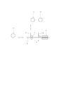
- FIG. 2 is a cross-sectional view showing a folded state (A to D) of the trunk and the bottom gusset material of FIG. It is explanatory drawing which shows the supply state of the trunk
- FIG. 10 is an exploded view of the plastic bag of FIG. 9.
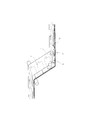
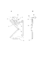
- FIG. 9 is explanatory drawing of the side gusset material of FIG. It is a perspective view which shows another Example. It is sectional drawing which shows the bending state (A, B) of another Example. It is sectional drawing which shows the bending state (AD) of a reference example. It is sectional drawing which shows the bending state (AC) of another Example. It is sectional drawing which shows the bending state (AD) of the conventional one. It is a top view which shows another Example.
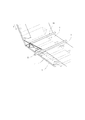
- FIG. 1 shows a bag making machine according to the present invention.
- This bag making machine is for producing the plastic bag shown in FIG.
- the plastic bag of FIG. 9 has barrel portions 1, 2, side gusset portion 3 and bottom gusset portion 4, and as shown in FIG.
- the parts 1 and 2 are overlapped with each other, and the side gusset part 4 extends along the side edges 5 of the body parts 1 and 2, is folded between the body parts 1 and 2 of both layers, and is folded in two.
- the body parts 1 and 2 and the side gusset part 3 are heat-sealed along both side edges 5 of the body parts 1 and 2, and the heat seal line 6 is formed along both side edges 5 of the body parts 1 and 2.
- one end portion of the side gusset portion 3 is bent at an angle of 45 °, folded between the side gusset portions 3 of both layers, and folded in two, whereby the auxiliary gusset portion 7 is formed.
- the bottom gusset portion 4 extends along the bottom edge 8 of the body portions 1 and 2 and is folded between the body portions 1 and 2 and the auxiliary gusset portion 7 of both layers and folded in two.
- the auxiliary gusset portion 7 and the bottom gusset portion 4 are heat-sealed along the side edges 5 of the body portions 1 and 2, and the heat seal line 6 is formed along the side edges 5 of the body portions 1 and 2.
- the parts 1 and 2 and the bottom gusset part 4 are heat-sealed along the bottom edge 8 of the body part 2, and the heat seal line 6 is formed along the bottom edge 8 of the body part 2. Therefore, a plastic bag can be expanded by the side gusset part 3 and the capacity
- the upper and lower body materials 1, 2 are overlapped with each other and sent in the length direction.
- the body materials 1 and 2 are for forming the body portions 1 and 2 of FIG. 10 and are made of a plastic film.
- feed rollers 9 and 10 are used in the body feeding mechanism, and the upper body material 1 is supplied from the raw fabric 11 and guided to the feed roller 9.
- the lower-layer body 2 is supplied from the raw fabric 12 and guided to the feed roller 9 so that the two-layer bodies 1 and 2 are overlapped with each other.
- the body materials 1 and 2 of both layers are guided to the feed roller 10, and the feed rollers 9 and 10 are driven and rotated by the drive motor, so that the continuous body materials 1 and 2 are fed in the length direction.
- the feed rollers 9 and 10 rotate intermittently, and in the feed direction X, the continuous body materials 1 and 2 are fed intermittently.
- the side gusset material 3 is supplied by the side gusset material supply mechanism, the side gusset material 3 is arranged in the width direction of the body materials 1 and 2, and is inserted between the body materials 1 and 2 of both layers. Is done. For example, before the side gusset material 3 is folded in advance and the upper and lower body materials 1 and 2 are overlapped with each other, the side gusset material 3 is formed in the lower layer every time the upper and lower body materials 1 and 2 are intermittently fed. It is supplied to the body 1, placed on the upper surface thereof, and arranged in the width direction.
- the side gusset material 3 is for forming the side gusset portion 3 of FIG. 10 and is made of a plastic film.
- a side gusset material 3 having a double width is used, and the side gusset material 3 is folded in two on both sides of the center line in the longitudinal direction and is overlapped in two layers. Further, one end portion thereof is bent at an angle of 45 °, is folded between the side gusset members 3 of both layers, is folded in two, and is superimposed on the two layers.
- the auxiliary gusset portion 7 shown in FIG. 10 is formed. And every time the two-layer body materials 1 and 2 are intermittently fed, it is supplied to the lower-layer body material 2, placed on the upper surface, and arranged in the width direction.
- the side gusset member 3 is inserted between the two body members 1 and 2.
- the side gusset material supply mechanism is the same as that of Japanese Patent Laid-Open No. 2000-254984, and the description of its configuration is omitted.
- the bottom gusset material 4 is supplied to the body material of one layer and is superimposed on the outer surface thereof, and the bottom gusset material 4 is arranged along one side edge 8 of the body materials 1 and 2. .
- One side edge 8 forms the bottom edge 8 of FIG.
- the bottom gusset material 4 and the body material of the other layer are attached at one side edge 8 of the body materials 1 and 2 and temporarily fixed.
- the bottom gusset material 4 is supplied from the raw fabric 13, supplied to the upper body material 1, and superposed on the upper surface thereof. Thereafter, the bottom gusset material 4 and the lower body 2 are temporarily fixed at one side edge 8 thereof.
- the ultrasonic sealing device 14 is used for the temporary fixing mechanism, and the bottom gusset material 4 and the lower body material 2 are ultrasonically sealed and adhered by the ultrasonic sealing device 14 every time the body materials 1 and 2 are intermittently fed. , Temporarily fixed. Therefore, the temporary fixing line 15 is formed along one side edge 8 of the body materials 1 and 2.
- the cylinder of one or the other layer is formed by the body material and the bottom gusset material guide mechanism.
- the material and the bottom gusset material 4 are guided, and the body material of one or the other layer is bent.
- the body of the one or other layer is folded back by the body and the bottom gusset material guide mechanism, and the bottom gusset material 4 is placed between the body materials 1 and 2 of both layers. Folded into.
- guide rods 16, 17 or plates are used for the body and bottom gusset material guide mechanism as in the body guide mechanism of Japanese Patent No. 3655627.
- the body members 1 and 2 in both layers pass through the guide rod 16 and are guided to the guide rod 17, and the upper body member 1 is guided by the guide rods 16 and 17 in the vicinity of one side edge 8 of the body members 1 and 2. Stand up and bend. When the guide rod 17 is reached, the upper-layer body 1 is completely bent.
- the side gusset material 3 has its two fold lines 18. Further, in this bag making machine, as in the case of Japanese Patent No. 3655627, the upper body 1 and the upper layer are formed by an ultrasonic sealing device at one end of the side gusset 3 at every intermittent feed of the bodies 1 and 2.
- the side gusset material 3 is ultrasonically sealed, adhered, and temporarily fixed, and the temporary fixing portion 20 is formed.
- the temporary fixing portion 20 is formed at the center position in the width direction of the side gusset material 3. Further, the lower body member 2 is ultrasonically sealed to the lower side gusset material 3 by an ultrasonic sealing device, and is attached and temporarily fixed to form the temporary fixing portion 21.
- the temporary fixing portion 21 is located on the center line in the length direction of the side gusset material 3.
- the upper-layer body 1 is guided by the guide rods 16 and 17 to stand, bend, and bend completely. Therefore, when the upper-layer body 1 stands and is bent, the bottom gusset material 4 is held by the lower-layer body 2, and the bottom gusset material 4 is pushed up by the upper-layer body 1 and stands. At the same time, the upper side gusset material 3 and the auxiliary gusset portion 7 are pulled up by the upper body material 1, and are raised and bent. Furthermore, the lower side gusset material 3 and the auxiliary gusset portion 7 are held by the lower body material 2, thereby opening both side gusset materials 3 and the auxiliary gusset portion 7, and covering them with the bottom gusset material 4.
- the side gusset material 3 and the auxiliary gusset material 7 of both layers are completely opened, thereby forming an opening surface thereof, and the bottom gusset material 4 is used as the side gusset material.
- the opening surface of the auxiliary gusset portion 7 are overlapped with each other, and the opening surface of the side gusset material 3 and the auxiliary gusset portion 7 is covered with the bottom gusset material 4.
- FIG. 1 As shown, the upper body 1 and the bottom gusset 4 are guided by other rods or plates, folded back, and the bottom gusset 4 is folded between the bodies 1 and 2 of both layers.
- the upper body 1 and the bottom gusset 4 are guided by the body and bottom gusset material guide mechanism, the upper body 1 is bent, and the bottom gusset 4 and both layers of the body are guided. 1 and 2 are combined, and the bottom gusset material 4 and the side gusset material 3 are combined. Thereafter, the upper body material 1 is folded back by the body material and bottom gusset material guide mechanism, and the bottom gusset material 4 is folded between the body materials 1 and 2 of both layers, and the upper body material 1 is folded and folded back. Thus, the bottom gusset material 4 and the side gusset material 3 are combined.
- the upper and lower body materials 1 and 2 pass through the slit blade 22, the horizontal seal device 23 and the vertical seal device 24, and are guided to the feed roller 10.
- the materials 1 and 2 are slit.
- the body materials 1 and 2 are slit along the slit line 25 of FIG.
- the body materials 1 and 2 and the side gusset material 3 of both layers are heat-sealed in the width direction of the body materials 1 and 2 by the lateral sealing device 23.
- the auxiliary gusset portion 7 and the bottom gusset material 4 are also heat-sealed by the lateral sealing device 23.
- the heat seal line 6 of FIG. 9 is formed.
- the longitudinal sealing device 24 heat-seal the body materials 1 and 2 and the bottom gusset material 4 of both layers along one side edge 8 thereof. Thereafter, for every intermittent feed of the body materials 1 and 2, the body materials 1 and 2 in both layers are cut by the cutter 26 in the width direction.
- the cutting position is the position of the side gusset material 3.
- the body materials 1, 2 and the side gusset material 3 of both layers are cut along the longitudinal center line of the side gusset material 3. As a result, both side edges 5 of FIG. 9 are formed.
- the materials of the two-layer body materials 1 and 2 the side gusset material 3 and the bottom gusset material 4 a laminate film obtained by laminating a sealant on the base material is used as the two-layer body materials 1 and 2 and the side gusset material 3.
- the inner surfaces of the two-layer body materials 1 and 2 are formed by a sealant such as polyethylene and polypropylene, and the outer surfaces of the two-layer body materials 1 and 2 are formed by a base material such as nylon.
- the outer surface of the side gusset material 3 is formed by a sealant such as polyethylene or polypropylene, and the inner surface of the side gusset material 3 is formed by a base material such as nylon.
- a sealant such as polyethylene or polypropylene
- a base material such as nylon.
- the plastic bag of FIG. 9 can be manufactured by this bag making machine, but the chuck 27 can be incorporated in the plastic bag as in the case of Japanese Patent No. 3655627.
- the side gusset material 3 can be bent at its tip to form a triangular flap 28 on the side gusset material 3.
- the upper body member 1 when manufacturing the plastic bag having the side gusset portion 3 and the bottom gusset portion 4, the upper body member 1 may be folded and folded, and the lower body member 2 is folded and bent. There is no need to wrap the part. Even if the lower body 2 is folded and the folded portion is not folded back, a plastic bag can be manufactured without any trouble, and the body guide mechanism can be simplified.
- the bottom gusset portion 4 is formed by folding the one-layer body as shown in the bag making machine of the publication, the upper-layer body 1 is previously folded, as shown in FIG.
- the bottom gusset portion 4 is formed by the bent portion.
- the bottom gusset portion 4 is folded back by the guide mechanism, the upper body material 1 is folded, the side gusset material 3 is lifted and opened, an opening surface is formed, and the bottom gusset portion 4 is overlaid on the opening surface of the side gusset material 3. Match. Thereafter, it is also conceivable that the upper body member 1 is folded back by the body member guide mechanism and the bottom gusset portion 4 is folded between the two body members 1 and 2.
- the bottom gusset material 4 and the lower body 2 are temporarily fixed at one side edge 8
- the bottom gusset material 4 is slit at the center line of each side gusset material 3, and the bottom in this state.
- the gusset material 4 and the lower body 2 may be temporarily fixed.
- the bottom gusset material 4 is easily pushed up by the upper-layer body 1, which is preferable.
- each side gusset material 3 a perforation or a micro joint is formed in the bottom gusset material 4, and when the bottom gusset material 4 is pushed up by the upper body 1, the bottom gusset material 4 is a perforation or a micro joint. You may make it tear off.
- the bottom gusset material 4 is supplied to the lower body 2 and overlapped with the lower surface, and then the bottom gusset 4 and the upper body 1 are temporarily fixed at one side edge. . Further, after temporary fixing, the upper body 1 may be guided by the body and bottom material guide mechanism, and may be folded and folded back.
- Japanese Patent No. 3655627 two plastic bags can be manufactured, but two square bottom bags can be manufactured in the method shown in FIG.
- the body 1 of one layer is divided in the width direction, and a pair of divided side edges are formed on the body 1 of one layer.
- the bottom gusset material 4 is supplied to the body 1 of one layer and overlapped with the outer surface thereof, and the center portion in the width direction of the bottom gusset material 4 is arranged along the divided side edge of the body 1 of one layer.
- the bottom gusset material 4 and the body material 2 of the other layer are attached at the center in the width direction of the bottom gusset material 4 and temporarily fixed between the respective divided side edges.
- the body materials 1 and 2 are fed, the body material 1 and the bottom gusset material 4 of one layer are guided by the body material and bottom gusset material guide mechanism in the vicinity of the split side edge of the material material 1 of the one layer.
- the body material 1 of one layer may be bent and the bottom gusset material 4 and the body materials 1 and 2 of both layers may be combined.
- the side gusset material 4 is supplied by the side gusset material supply mechanism, and the side gusset material 4 is arranged in the width direction of the body materials 1 and 2 and inserted between the body materials 1 and 2 of both layers. You may make it the side gusset material 4 be located in the width direction both sides of 1 division
- the body 1 of one layer is folded back by the body and bottom gusset material guide mechanism, and the bottom gusset material 4 is folded between the bodies 1 and 2 of both layers.
- the bottom gusset material 4 and the side gusset material 3 are combined by folding and folding back the body material 1 of one layer.
- the two-layer body materials 1 and 2 and the bottom gusset material 4 are heat-sealed along the divided side edge of the one-layer body material 1, so The side gusset material 3 is heat-sealed in the width direction of the body materials 1 and 2. Furthermore, if the two-layer body materials 1 and 2 and the bottom gusset material 4 are slit at the center portion in the width direction of the bottom gusset material 4 by the slit blade, two plastic bags can be manufactured.
- the body part of the plastic bag can be formed by 1, 2, the bottom gusset part of the plastic bag can be formed by the bottom gusset material 4, and the side gusset part of the plastic bag can be formed by the side gusset material 3.
- each slit blade 29 slits the body 1 of one layer along the longitudinal slit line 30, thereby dividing the body 1 of one layer, and the pair of divided side edges is the body. You may make it oppose at intervals in the width direction of 1 and 2.
- each divided side edge is guided to the guide roller 31, and a portion between each divided side edge is wound up by a hoisting machine, and this is separated from the body 1 of one layer. Then, the bottom gusset material 4 and the body 2 of the other layer may be directly attached and temporarily fixed.
- a pair of perforation forming blades are used for the dividing mechanism, and the perforation forming blades are arranged at intervals in the width direction of the barrels 1 and 2.
- Each perforation forming blade forms a perforation extending in the length direction of the body 1 of one layer, whereby the body 1 of one layer is divided, and a pair of divided side edges are formed of the body. You may make it oppose at intervals in the width direction of 1 and 2.
- each divided side edge is guided to the guide roller 31, and a portion between each divided side edge is wound up by a hoisting machine, torn off, and separated from the body material 1 of one layer. Then, the bottom gusset material 4 and the body 2 of the other layer may be directly attached and temporarily fixed.
- the bottom gusset material 4 may be supplied to the body material 1 of one layer before the upper and lower body materials 1 and 2 are overlapped. Then, after the body materials 1 and 2 are overlapped, the bottom gusset material 4 and the body material 2 of the other layer may be temporarily fixed by the ultrasonic sealing device 14.
- the bottom gusset material 4 and the one-layer body 1 are adhered to the center portion of the bottom gusset material 4 by a temporary fixing mechanism such as an ultrasonic sealing device 32. Temporarily fix. Then, when the bottom gusset material 4 and the body 2 of the other layer are temporarily fixed at the center portion of the bottom gusset material 4, the portion between each divided side edge is separated from the body 1 of one layer, and each divided side The portion between the edges and the body 2 of the other layer may be directly attached and temporarily fixed, and the bottom gusset material 4 and the body 2 of the other layer may be indirectly attached and temporarily fixed.
- a temporary fixing mechanism such as an ultrasonic sealing device 32.
- bottom gusset material 4 After the bottom gusset material 4 is supplied, when the bottom gusset material 4 and the one-layer body 1 are attached and temporarily fixed, the bottom gusset material 4 and the one-layer body 1 are fed together, thereby The positional relationship can be maintained, which is preferable.
- the plastic film supplied from the raw fabric is slit along the longitudinal slit line by the slit blade 33, and the body 1 and the bottom gusset material 4 of one layer are slit.
- the bottom gusset material 4 may be guided by a bottom gusset material guide mechanism such as a guide roller 34, the direction thereof may be changed, and the bottom gusset material 4 may be supplied to the body material of one or the other layer.
- the printed material when the printed material is provided on the body material 1 and the bottom gusset material 4 of one layer, the printed material does not shift between the body material 1 and the bottom gusset material 4, which is preferable. It is also possible to apply tension to the bottom gusset material 4 by engaging the dancer roller 35 with the bottom gusset material 4.
- a plastic film is supplied from an original fabric, slit with a slit blade 36, and divided into a bottom gusset material 4 and a side gusset material 3. Further, the side gusset material 3 is guided by the guide mechanism and is bent from both sides. Thereafter, the side gusset material 3 may be supplied to the lower body 2 and the bottom gusset 4 may be guided to the upper body 1 and overlapped.
- the bottom gusset material 4 is clamped or clamped by the vacuum pad.
- the side gusset material 4 can have a certain length A, and the bottom gusset material 4 can have a shorter length B.
- a mark is formed on the bottom gusset material 4, detected by the mark sensor 38, air is ejected from the air dancer 39 based on the detection signal, and the bottom gusset material 4 is pushed down by the air. Thereafter, the bottom gusset material 4 may be melted by the heater 40 to form a fusing line 41, and the bottom gusset material 4 may have a shorter length B than the side gusset material 3.
- air can be blown from the air dancer 39 and the bottom gusset material 4 can be melted by the heater 40.
- a plastic film is supplied from a raw fabric and stored in an accumulator, and then the plastic film is slit with a slit blade 42 and divided into a body 1 and a body 2 as shown in FIG. Further, the slit blade 43 may be slit to divide the body material 1 and the bottom gusset material 4. Further, when the bottom gusset material 4 is guided to the turn bar 44, the direction of the bottom gusset material 4 is changed by the turn bar 44, and the turn bar 44 is moved in the plastic film supply direction Y, the bottom gusset material 4 is moved by the turn bar 44, Can be adjusted so that the bottom gusset material 4 is positioned in the right direction in the width direction of the body 1.
- the bottom gusset material 4 is guided to the guide rollers 45, 46, the body 1 is guided to the guide roller 47, the body 2 is guided to the guide roller 48, and the bottom gusset material 4 and the guide rollers 45, 46, 47, 48 are guided.
- the direction of the body materials 1 and 2 is changed.
- the bottom gusset material 4 is moved by the guide roller 45 so that the printed pattern does not shift between the body 1 and the bottom gusset material 4. . It is also possible to temporarily fix the bottom gusset material 4 and the body material 1 with an ultrasonic sealing device 49 or hot melt.
- the bottom gusset material 4 is continuously fed, passed through the dancer rollers 50 and 51, and superimposed on the body material 1.
- the bottom material 40 and the body material 1 are temporarily fixed.
- the body 1 is intermittently sent, and the bottom gusset material 4 is stored in the dancer rollers 50 and 51 and supplied from the dancer rollers 50 and 51.
- the drive mechanism is connected to the dancer roller 51, the dancer roller 51 is pushed down by the drive mechanism, and tension is applied to the bottom material 4.
- a mark is attached to the body 1 and the bottom gusset material 4, and the mark is detected by the mark sensor 38.
- the drive mechanism In response to the detection signal, the drive mechanism is controlled by the control device, and the tension is adjusted. As a result, the printed pattern does not deviate between the bottom gusset material 4 and the body material 1.
- a braking force is applied to the dancer roller 51 to cause friction between the bottom gusset material 4 and the dancer roller 51.
- the brake force can be adjusted by the control device so that the printed pattern does not shift between the bottom gusset material 4 and the body 1.
Landscapes
- Making Paper Articles (AREA)
- Bag Frames (AREA)
Abstract
Priority Applications (11)
| Application Number | Priority Date | Filing Date | Title |
|---|---|---|---|
| CA2722353A CA2722353C (fr) | 2008-04-24 | 2009-04-24 | Appareil de fabrication de sacs en plastique |
| AU2009238907A AU2009238907B2 (en) | 2008-04-24 | 2009-04-24 | Plastic bag making apparatus |
| EP09736053.1A EP2279857B1 (fr) | 2008-04-24 | 2009-04-24 | Machine de fabrication de sac |
| CN2009801242490A CN102076491B (zh) | 2008-04-24 | 2009-04-24 | 制袋机 |
| US12/988,879 US20110039676A1 (en) | 2008-04-24 | 2009-04-24 | Plastic bag making apparatus |
| DK09736053.1T DK2279857T3 (da) | 2008-04-24 | 2009-04-24 | Indretning til fremstilling af poser |
| JP2009542277A JP4612740B2 (ja) | 2008-04-24 | 2009-04-24 | 製袋機 |
| US15/473,673 US20170203532A1 (en) | 2008-04-24 | 2017-03-30 | Plastic Bag Making Apparatus |
| US15/597,327 US20170266905A1 (en) | 2008-04-24 | 2017-05-17 | Plastic Bag Making Apparatus |
| US15/597,441 US20170266906A1 (en) | 2008-04-24 | 2017-05-17 | Plastic Bag Making Apparatus |
| US15/597,387 US20170259518A1 (en) | 2008-04-24 | 2017-05-17 | Plastic Bag Making Apparatus |
Applications Claiming Priority (2)
| Application Number | Priority Date | Filing Date | Title |
|---|---|---|---|
| JP2008114658 | 2008-04-24 | ||
| JP2008-114658 | 2008-04-24 |
Related Child Applications (5)
| Application Number | Title | Priority Date | Filing Date |
|---|---|---|---|
| US12/988,879 A-371-Of-International US20110039676A1 (en) | 2008-04-24 | 2009-04-24 | Plastic bag making apparatus |
| US15/473,673 Division US20170203532A1 (en) | 2008-04-24 | 2017-03-30 | Plastic Bag Making Apparatus |
| US15/597,327 Division US20170266905A1 (en) | 2008-04-24 | 2017-05-17 | Plastic Bag Making Apparatus |
| US15/597,387 Division US20170259518A1 (en) | 2008-04-24 | 2017-05-17 | Plastic Bag Making Apparatus |
| US15/597,441 Division US20170266906A1 (en) | 2008-04-24 | 2017-05-17 | Plastic Bag Making Apparatus |
Publications (1)
| Publication Number | Publication Date |
|---|---|
| WO2009131214A1 true WO2009131214A1 (fr) | 2009-10-29 |
Family
ID=41216940
Family Applications (1)
| Application Number | Title | Priority Date | Filing Date |
|---|---|---|---|
| PCT/JP2009/058169 Ceased WO2009131214A1 (fr) | 2008-04-24 | 2009-04-24 | Machine de fabrication de sac |
Country Status (9)
| Country | Link |
|---|---|
| US (5) | US20110039676A1 (fr) |
| EP (3) | EP3292996A1 (fr) |
| JP (4) | JP4612740B2 (fr) |
| CN (1) | CN102076491B (fr) |
| AU (1) | AU2009238907B2 (fr) |
| CA (1) | CA2722353C (fr) |
| DK (1) | DK2279857T3 (fr) |
| RU (1) | RU2446052C1 (fr) |
| WO (1) | WO2009131214A1 (fr) |
Cited By (5)
| Publication number | Priority date | Publication date | Assignee | Title |
|---|---|---|---|---|
| JPWO2009131214A1 (ja) * | 2008-04-24 | 2011-08-25 | トタニ技研工業株式会社 | 製袋機 |
| JP2017128017A (ja) * | 2016-01-19 | 2017-07-27 | 西部機械株式会社 | 底ガゼットを有する袋を製袋する製袋機 |
| JPWO2016199863A1 (ja) * | 2015-06-11 | 2017-09-28 | トタニ技研工業株式会社 | プラスチック袋を製造する製袋機及び方法 |
| WO2020235188A1 (fr) * | 2019-05-21 | 2020-11-26 | トタニ技研工業株式会社 | Procédé de fabrication de sacs et dispositif de fabrication de sacs |
| WO2021210253A1 (fr) | 2020-04-17 | 2021-10-21 | トタニ技研工業株式会社 | Machine de fabrication de sac et procédé de fabrication de sac |
Families Citing this family (15)
| Publication number | Priority date | Publication date | Assignee | Title |
|---|---|---|---|---|
| JP4499832B1 (ja) | 2010-02-05 | 2010-07-07 | トタニ技研工業株式会社 | 製袋機 |
| JP6025338B2 (ja) * | 2012-02-08 | 2016-11-16 | 株式会社フジシールインターナショナル | 製袋機 |
| JP5957752B2 (ja) * | 2012-03-23 | 2016-07-27 | 株式会社フジシール | 角底パウチ |
| JP5323249B1 (ja) | 2012-12-28 | 2013-10-23 | トタニ技研工業株式会社 | 製袋機 |
| CN103171170B (zh) * | 2013-04-09 | 2015-08-26 | 上海西毕尔包装机械有限公司 | 用在塑料制袋机上同时形成两个菱形翻角的机构及方法 |
| EP3046754B1 (fr) * | 2013-09-18 | 2019-01-16 | Mamata Machinery Pvt. Ltd. | Machine et procédé de fabrication de poches en plastique |
| AU2014334749B2 (en) * | 2013-10-16 | 2017-08-31 | Innoflex Incorporated | Bottom and side gusseted package and method |
| JP5965509B1 (ja) * | 2015-03-24 | 2016-08-03 | トタニ技研工業株式会社 | 製袋機 |
| ES2600166B1 (es) * | 2015-07-24 | 2017-11-17 | Pfm Ibérica Packaging Machinery, S.A. | Un procedimiento para la fabricación de contenedores flexibles que comprenden una base inferior de configuración esencialmente rectangular |
| RU2706442C1 (ru) * | 2016-07-14 | 2019-11-19 | Тотани Корпорейшн | Установка для изготовления пластикового пакета и способ изготовления пластикового пакета |
| AU2017359068B2 (en) * | 2016-11-08 | 2020-02-20 | Totani Corporation | Plastic bag and method for manufacturing plastic bag |
| EA033916B1 (ru) * | 2017-01-23 | 2019-12-10 | Общество С Ограниченной Ответственностью "Производственная Компания Авм" (Ооо "Авм") | Способ изготовления сумки |
| CN107097461A (zh) * | 2017-06-26 | 2017-08-29 | 东莞市鑫鸣机械科技有限公司 | 一种八边封五面袋的全自动生产设备 |
| JP7279931B2 (ja) * | 2019-03-28 | 2023-05-23 | 株式会社タキガワ・コーポレーション・ジャパン | ガゼット袋の製造方法 |
| WO2022004102A1 (fr) * | 2020-06-30 | 2022-01-06 | トタニ技研工業株式会社 | Dispositif de détection de défaut et machine de fabrication de sacs |
Citations (8)
| Publication number | Priority date | Publication date | Assignee | Title |
|---|---|---|---|---|
| JPH0254984A (ja) | 1988-08-19 | 1990-02-23 | Fujitsu General Ltd | マザーボード |
| JPH0439031A (ja) * | 1990-06-04 | 1992-02-10 | Horie Honten:Kk | フィルムシート材熱溶断・溶着装置 |
| JP2000062795A (ja) * | 1998-08-14 | 2000-02-29 | Totani Giken Kogyo Kk | プラスチック袋およびその製造方法 |
| JP2000334861A (ja) * | 1999-05-26 | 2000-12-05 | Sanwa Kogyo Kk | 自立袋連続製造方法 |
| JP3455627B2 (ja) | 1996-03-22 | 2003-10-14 | 日産ディーゼル工業株式会社 | 車両における覚醒度低下検出装置 |
| JP2004338417A (ja) * | 2004-09-07 | 2004-12-02 | Totani Corp | 製袋機 |
| JP3655627B2 (ja) | 2002-07-24 | 2005-06-02 | トタニ技研工業株式会社 | 製袋機 |
| JP2005231204A (ja) * | 2004-02-19 | 2005-09-02 | Totani Corp | 製袋機 |
Family Cites Families (6)
| Publication number | Priority date | Publication date | Assignee | Title |
|---|---|---|---|---|
| US5938337A (en) * | 1998-10-13 | 1999-08-17 | Tenneco Packaging Inc. | Bottom filled, bottom-gusseted bag and method of making the same |
| DE19910264A1 (de) * | 1999-03-08 | 2000-09-14 | Reinhold Klaus Masch & Geraete | Verfahren zum Herstellen eines Packmittels aus Kunststoffolie oder dergleichen verschweißbarem Material |
| US6517660B2 (en) * | 2000-11-30 | 2003-02-11 | Illinois Tool Works Inc. | Method of forming gusseted reclosable bags |
| US7104942B2 (en) * | 2003-05-21 | 2006-09-12 | Greg Tan | Side seamed plastic produce bag, method of making and dispenser for same |
| DE102004040624B3 (de) * | 2004-08-21 | 2006-02-16 | Hdg Verpackungsmaschinen Gmbh | Verfahren zur Herstellung eines geschlossenen Verpackungsbeutels |
| WO2009131214A1 (fr) * | 2008-04-24 | 2009-10-29 | トタニ技研工業株式会社 | Machine de fabrication de sac |
-
2009
- 2009-04-24 WO PCT/JP2009/058169 patent/WO2009131214A1/fr not_active Ceased
- 2009-04-24 EP EP17194632.0A patent/EP3292996A1/fr not_active Withdrawn
- 2009-04-24 CA CA2722353A patent/CA2722353C/fr not_active Expired - Fee Related
- 2009-04-24 US US12/988,879 patent/US20110039676A1/en not_active Abandoned
- 2009-04-24 AU AU2009238907A patent/AU2009238907B2/en not_active Ceased
- 2009-04-24 CN CN2009801242490A patent/CN102076491B/zh not_active Expired - Fee Related
- 2009-04-24 EP EP17194637.9A patent/EP3292997A1/fr not_active Withdrawn
- 2009-04-24 RU RU2010147824/12A patent/RU2446052C1/ru not_active IP Right Cessation
- 2009-04-24 JP JP2009542277A patent/JP4612740B2/ja not_active Expired - Fee Related
- 2009-04-24 DK DK09736053.1T patent/DK2279857T3/da active
- 2009-04-24 EP EP09736053.1A patent/EP2279857B1/fr not_active Not-in-force
- 2009-10-16 JP JP2009239209A patent/JP4469412B2/ja not_active Expired - Fee Related
- 2009-10-16 JP JP2009239208A patent/JP4429379B2/ja not_active Expired - Fee Related
- 2009-10-16 JP JP2009239210A patent/JP2010036587A/ja active Pending
-
2017
- 2017-03-30 US US15/473,673 patent/US20170203532A1/en not_active Abandoned
- 2017-05-17 US US15/597,387 patent/US20170259518A1/en not_active Abandoned
- 2017-05-17 US US15/597,441 patent/US20170266906A1/en not_active Abandoned
- 2017-05-17 US US15/597,327 patent/US20170266905A1/en not_active Abandoned
Patent Citations (8)
| Publication number | Priority date | Publication date | Assignee | Title |
|---|---|---|---|---|
| JPH0254984A (ja) | 1988-08-19 | 1990-02-23 | Fujitsu General Ltd | マザーボード |
| JPH0439031A (ja) * | 1990-06-04 | 1992-02-10 | Horie Honten:Kk | フィルムシート材熱溶断・溶着装置 |
| JP3455627B2 (ja) | 1996-03-22 | 2003-10-14 | 日産ディーゼル工業株式会社 | 車両における覚醒度低下検出装置 |
| JP2000062795A (ja) * | 1998-08-14 | 2000-02-29 | Totani Giken Kogyo Kk | プラスチック袋およびその製造方法 |
| JP2000334861A (ja) * | 1999-05-26 | 2000-12-05 | Sanwa Kogyo Kk | 自立袋連続製造方法 |
| JP3655627B2 (ja) | 2002-07-24 | 2005-06-02 | トタニ技研工業株式会社 | 製袋機 |
| JP2005231204A (ja) * | 2004-02-19 | 2005-09-02 | Totani Corp | 製袋機 |
| JP2004338417A (ja) * | 2004-09-07 | 2004-12-02 | Totani Corp | 製袋機 |
Non-Patent Citations (1)
| Title |
|---|
| See also references of EP2279857A4 |
Cited By (12)
| Publication number | Priority date | Publication date | Assignee | Title |
|---|---|---|---|---|
| JPWO2009131214A1 (ja) * | 2008-04-24 | 2011-08-25 | トタニ技研工業株式会社 | 製袋機 |
| JPWO2016199863A1 (ja) * | 2015-06-11 | 2017-09-28 | トタニ技研工業株式会社 | プラスチック袋を製造する製袋機及び方法 |
| RU2670862C1 (ru) * | 2015-06-11 | 2018-10-25 | Тотани Корпорейшн | Установка и способ для изготовления пластиковых пакетов |
| RU2670862C9 (ru) * | 2015-06-11 | 2018-11-30 | Тотани Корпорейшн | Установка и способ для изготовления пластиковых пакетов |
| JP2017128017A (ja) * | 2016-01-19 | 2017-07-27 | 西部機械株式会社 | 底ガゼットを有する袋を製袋する製袋機 |
| WO2020235188A1 (fr) * | 2019-05-21 | 2020-11-26 | トタニ技研工業株式会社 | Procédé de fabrication de sacs et dispositif de fabrication de sacs |
| JPWO2020235188A1 (ja) * | 2019-05-21 | 2021-10-14 | トタニ技研工業株式会社 | 製袋方法および製袋機 |
| JP7122044B2 (ja) | 2019-05-21 | 2022-08-19 | トタニ技研工業株式会社 | 製袋方法および製袋機 |
| US11926118B2 (en) | 2019-05-21 | 2024-03-12 | Totani Corporation | Bag making method and bag making apparatus |
| US12350902B2 (en) | 2019-05-21 | 2025-07-08 | Totani Corporation | Bag making method and bag making apparatus |
| WO2021210253A1 (fr) | 2020-04-17 | 2021-10-21 | トタニ技研工業株式会社 | Machine de fabrication de sac et procédé de fabrication de sac |
| US12454113B2 (en) | 2020-04-17 | 2025-10-28 | Totani Corporation | Bag making apparatus and bag making method |
Also Published As
| Publication number | Publication date |
|---|---|
| CN102076491B (zh) | 2013-01-09 |
| US20170259518A1 (en) | 2017-09-14 |
| JP4429379B2 (ja) | 2010-03-10 |
| US20110039676A1 (en) | 2011-02-17 |
| EP3292997A1 (fr) | 2018-03-14 |
| EP2279857B1 (fr) | 2017-11-22 |
| JP2010036586A (ja) | 2010-02-18 |
| US20170266906A1 (en) | 2017-09-21 |
| JP4469412B2 (ja) | 2010-05-26 |
| JP2010036585A (ja) | 2010-02-18 |
| AU2009238907B2 (en) | 2012-04-19 |
| US20170203532A1 (en) | 2017-07-20 |
| CN102076491A (zh) | 2011-05-25 |
| CA2722353C (fr) | 2014-07-08 |
| AU2009238907A1 (en) | 2009-10-29 |
| US20170266905A1 (en) | 2017-09-21 |
| CA2722353A1 (fr) | 2009-10-29 |
| EP3292996A1 (fr) | 2018-03-14 |
| DK2279857T3 (da) | 2018-01-29 |
| EP2279857A4 (fr) | 2015-09-30 |
| JPWO2009131214A1 (ja) | 2011-08-25 |
| EP2279857A1 (fr) | 2011-02-02 |
| JP4612740B2 (ja) | 2011-01-12 |
| JP2010036587A (ja) | 2010-02-18 |
| RU2446052C1 (ru) | 2012-03-27 |
Similar Documents
| Publication | Publication Date | Title |
|---|---|---|
| JP4429379B2 (ja) | 製袋機 | |
| US8241194B2 (en) | Process for producing web sections from a flexible web material as well as for producing packing containers | |
| JP3655627B2 (ja) | 製袋機 | |
| WO2010055571A1 (fr) | Machine à fabriquer des sacs | |
| WO2011037021A1 (fr) | Sachet pour emballage de médicaments et feuille destinée à celui-ci | |
| JP2005529773A (ja) | フィルム・ウェブから薄壁容器を製造する方法および製造設備 | |
| US9802378B2 (en) | Appartus for, and method of, producing a bag from paper, and paper bag | |
| JP4320353B2 (ja) | 製袋機 | |
| CN105555493A (zh) | 用于由织物生成袋的方法和装置 | |
| JP2025516900A (ja) | 強化パッケージを製造するための包装機 | |
| JP4688949B2 (ja) | 製袋機 | |
| JP4499468B2 (ja) | 製袋機 | |
| HK1151262B (en) | Bag-making machine | |
| GB2483437A (en) | Method of producing a bag with an outer jacket |
Legal Events
| Date | Code | Title | Description |
|---|---|---|---|
| WWE | Wipo information: entry into national phase |
Ref document number: 200980124249.0 Country of ref document: CN |
|
| WWE | Wipo information: entry into national phase |
Ref document number: 2009542277 Country of ref document: JP |
|
| 121 | Ep: the epo has been informed by wipo that ep was designated in this application |
Ref document number: 09736053 Country of ref document: EP Kind code of ref document: A1 |
|
| WWE | Wipo information: entry into national phase |
Ref document number: 2722353 Country of ref document: CA |
|
| NENP | Non-entry into the national phase |
Ref country code: DE |
|
| WWE | Wipo information: entry into national phase |
Ref document number: 4031/KOLNP/2010 Country of ref document: IN |
|
| WWE | Wipo information: entry into national phase |
Ref document number: 2009238907 Country of ref document: AU |
|
| REEP | Request for entry into the european phase |
Ref document number: 2009736053 Country of ref document: EP |
|
| WWE | Wipo information: entry into national phase |
Ref document number: 12988879 Country of ref document: US Ref document number: 2009736053 Country of ref document: EP |
|
| WWE | Wipo information: entry into national phase |
Ref document number: 2010147824 Country of ref document: RU |
|
| ENP | Entry into the national phase |
Ref document number: 2009238907 Country of ref document: AU Date of ref document: 20090424 Kind code of ref document: A |