WO2009133785A1 - 試料低温保存容器および生体輸送支援システム - Google Patents
試料低温保存容器および生体輸送支援システム Download PDFInfo
- Publication number
- WO2009133785A1 WO2009133785A1 PCT/JP2009/057880 JP2009057880W WO2009133785A1 WO 2009133785 A1 WO2009133785 A1 WO 2009133785A1 JP 2009057880 W JP2009057880 W JP 2009057880W WO 2009133785 A1 WO2009133785 A1 WO 2009133785A1
- Authority
- WO
- WIPO (PCT)
- Prior art keywords
- container
- sample
- information
- storage container
- storage
- Prior art date
- Legal status (The legal status is an assumption and is not a legal conclusion. Google has not performed a legal analysis and makes no representation as to the accuracy of the status listed.)
- Ceased
Links
Images







Classifications
-
- A—HUMAN NECESSITIES
- A01—AGRICULTURE; FORESTRY; ANIMAL HUSBANDRY; HUNTING; TRAPPING; FISHING
- A01N—PRESERVATION OF BODIES OF HUMANS OR ANIMALS OR PLANTS OR PARTS THEREOF; BIOCIDES, e.g. AS DISINFECTANTS, AS PESTICIDES OR AS HERBICIDES; PEST REPELLANTS OR ATTRACTANTS; PLANT GROWTH REGULATORS
- A01N1/00—Preservation of bodies of humans or animals, or parts thereof
- A01N1/10—Preservation of living parts
- A01N1/14—Mechanical aspects of preservation; Apparatus or containers therefor
- A01N1/142—Apparatus
- A01N1/144—Apparatus for temperature control, e.g. refrigerators or freeze-drying apparatus
- A01N1/145—Stationary or portable vessels generating cryogenic temperatures, e.g. liquid nitrogen baths
-
- B—PERFORMING OPERATIONS; TRANSPORTING
- B01—PHYSICAL OR CHEMICAL PROCESSES OR APPARATUS IN GENERAL
- B01L—CHEMICAL OR PHYSICAL LABORATORY APPARATUS FOR GENERAL USE
- B01L7/00—Heating or cooling apparatus; Heat insulating devices
- B01L7/50—Cryostats
-
- B—PERFORMING OPERATIONS; TRANSPORTING
- B01—PHYSICAL OR CHEMICAL PROCESSES OR APPARATUS IN GENERAL
- B01L—CHEMICAL OR PHYSICAL LABORATORY APPARATUS FOR GENERAL USE
- B01L2200/00—Solutions for specific problems relating to chemical or physical laboratory apparatus
- B01L2200/14—Process control and prevention of errors
- B01L2200/143—Quality control, feedback systems
-
- B—PERFORMING OPERATIONS; TRANSPORTING
- B01—PHYSICAL OR CHEMICAL PROCESSES OR APPARATUS IN GENERAL
- B01L—CHEMICAL OR PHYSICAL LABORATORY APPARATUS FOR GENERAL USE
- B01L2200/00—Solutions for specific problems relating to chemical or physical laboratory apparatus
- B01L2200/18—Transport of container or devices
-
- B—PERFORMING OPERATIONS; TRANSPORTING
- B01—PHYSICAL OR CHEMICAL PROCESSES OR APPARATUS IN GENERAL
- B01L—CHEMICAL OR PHYSICAL LABORATORY APPARATUS FOR GENERAL USE
- B01L2300/00—Additional constructional details
- B01L2300/02—Identification, exchange or storage of information
- B01L2300/024—Storing results with means integrated into the container
-
- B—PERFORMING OPERATIONS; TRANSPORTING
- B01—PHYSICAL OR CHEMICAL PROCESSES OR APPARATUS IN GENERAL
- B01L—CHEMICAL OR PHYSICAL LABORATORY APPARATUS FOR GENERAL USE
- B01L3/00—Containers or dishes for laboratory use, e.g. laboratory glassware; Droppers
- B01L3/50—Containers for the purpose of retaining a material to be analysed, e.g. test tubes
- B01L3/508—Rigid containers without fluid transport within
-
- G—PHYSICS
- G01—MEASURING; TESTING
- G01N—INVESTIGATING OR ANALYSING MATERIALS BY DETERMINING THEIR CHEMICAL OR PHYSICAL PROPERTIES
- G01N1/00—Sampling; Preparing specimens for investigation
- G01N1/28—Preparing specimens for investigation including physical details of (bio-)chemical methods covered elsewhere, e.g. G01N33/50, C12Q
- G01N1/42—Low-temperature sample treatment, e.g. cryofixation
Definitions
- the present invention relates to a sample cryopreservation container used for low-temperature transport and storage of a sample, and a biological transport support system using the same.
- sample organic substances such as cells, microorganisms, and proteins
- a point a predetermined storage location
- B point another use location
- the sample is transported while being kept at a low temperature.
- a sample low-temperature storage container used for such an application, a container having a structure in which liquid nitrogen as a refrigerant is filled in a vacuum heat insulating container and the sample is kept cold by this liquid nitrogen is known.
- the shipper injects liquid nitrogen into the container and then stores the sample.
- the sample is transported to point B by a vehicle or the like while being kept at around ⁇ 196 ° C.
- the sample is picked up by the recipient and then stored, for example, in a freezer maintained at ⁇ 140 ° C. or lower.
- the inside of the container has a positive pressure higher than the external pressure due to the evaporating gas of the refrigerant constantly generated. Therefore, on the contrary, in order to prevent the container from bursting, the sample low-temperature storage container has a structure in which the evaporated gas leaks to the outside so that the internal pressure is constant. Thus, the evaporative gas continues to leak from the inside of the sample cryopreservation container to the outside, so that contaminants such as bacteria are prevented from entering the inside of the sample cryopreservation container, and the quality of the sample can be maintained. In this way, it is guaranteed that the quality of the sample is not deteriorated or contaminated during transportation, that is, the state at the time of shipment at point A is also maintained at point B. Guarantee is extremely important for the recipient.
- sample low-temperature storage containers that use refrigerants that sublimate or evaporate, such as dry ice and liquid nitrogen
- refrigerants that sublimate or evaporate such as dry ice and liquid nitrogen
- there is a risk of oxygen deficiency due to evaporative gas and there is a risk of refrigerant outflow or abnormal evaporation due to container overturning or breaking.
- it is generally not possible to carry such a sample cryopreservation container by bringing it into a cabin of a highly airtight aircraft or the like in a passenger car and transporting it in a special manner (for example, transport for tailoring to prevent falling).
- transport for tailoring to prevent falling For example, it is necessary to store the cargo in a transport room separate from the passengers using a cargo.
- Such a method has a problem that transportation costs increase.
- the sample can be cooled and held at ⁇ 140 ° C. or lower using a refrigerator.
- Proposal of a storage device with a structure that can easily carry in / out the (microplate) to the cold insulation chamber without the outside air flowing into the cold insulation chamber or the cold air inside the cold insulation chamber flowing out to the outside. (For example, refer to Patent Document 1). More specifically, when the sample container is accommodated in the storage device from the outside, the sample container is first accommodated in a front chamber provided in the storage device. At this time, the front chamber and the cold insulation chamber are isolated.
- the inner door provided between the front chamber and the cool chamber After shutting off the front chamber and the outside, the inner door provided between the front chamber and the cool chamber is opened, the sample container is mechanically transferred from the front chamber to the cool chamber, and then the inner door is closed.
- the reverse operation is performed.
- the present invention has been made in view of such circumstances, and does not use a refrigerant that evaporates or evaporates, such as liquid nitrogen, and allows a sample recipient to easily check the integrity of the sample at the time of receipt.
- the purpose is to provide.
- the patient's own skin cells for example, from the hospital at point A are transported to the culture center at point B, and the artificial multifunctional stem (iPS) cells made at the culture center are transported again to the hospital at point A, where the patient
- iPS artificial multifunctional stem
- the sample is sent again from the hospital at point A without performing the culture. Processing can be performed.
- the present invention has been made in view of such circumstances, and an object thereof is to provide a living body transportation support system that can guarantee that a sample (living body) is not contaminated (soundness).
- the sample cryopreservation container according to the present invention has a structure in which the sample stored in the containment container is cooled and held by a refrigerator, and has chemical or physical characteristics due to the adhesion of contaminants to the room temperature region in the sample cryopreservation container. It is possible to inspect the presence or absence of contaminants into the inside of the sample cryopreservation container by arranging a sensing element that changes and inspecting the sensing element from the outside of the sample cryopreservation container in a non-contact manner. is there.
- the living body transportation support system includes a storage means for storing an inspection result of the presence / absence of intrusion of contaminants into the sample cryopreservation container, and a first transportable source of the sample.
- the inspection result is transmitted by connecting to at least two terminals among a terminal, a second terminal operable by the sample transporter, and a third terminal operable by the sample transport destination. And a communication means.
- the recipient of a sample can provide the sample cryopreservation container which can confirm the soundness of a sample easily at the time of receipt. Moreover, according to the present invention, it is possible to provide a living body transportation support system that can guarantee that the sample (living body) is not contaminated (soundness).
- the display screen for assisting to display a list of culture matching information and to register (provisional) order approval. It is an example of the display screen for assisting to display a list of transportation request information and register (provisional) order approval. It is an example of the display screen for assisting to display a list of culture request information and register (provisional) order approval. It is an example of the display screen for assisting to display a list of culture request information and register (provisional) order approval. It is an example of the display screen for assisting to display a list of quality information and consignment information at the time of receipt of goods and to accept (main) order approval registration. It is an example of the display screen which displays the list of transportation environment information.
- a display screen for assisting in displaying a list of quality information and unacknowledgment information (conditions) at the time of unloading (main) and receiving approval registration. It is an example of the display screen for assisting to display culture environment information as a list and to input culture environment information. It is an example of the display screen for assisting to display a list of culture completion information and quality information at the time of culture completion and to (register) culture completion approval registration. It is an example of the display screen for assisting to display a list of return (transportation) request information and register (provisional) order approval. It is an example of a display screen for assisting in displaying a list of quality information at the time of receiving goods and returning (transportation) consignment information (main) order approval registration.
- the display screen which displays the list of the transportation environment information at the time of return. It is an example of a display screen for assisting in displaying a list of quality information and unacknowledgment information (conditions) at the time of unloading (main) and receiving approval registration.
- FIG. 1 is a sectional view showing a schematic structure of a sample cryogenic storage container (hereinafter referred to as “storage container”) 100 according to an embodiment of the present invention.
- the storage container 100 is roughly attached to a storage container 11 (storage means) for storing a sample container S in which an object to be cooled (sample) is stored, and the storage container 11, and the sample container S is attached to the storage container 11.
- the introduction container 13 (sample introduction means) having the opening 12 for taking in and out, the lid member 14 (closure means) for closing the opening 12 of the introduction container 13, and the sample container S stored in the storage container 11 are cooled.
- a heat insulating container 16 (heat insulating means) that accommodates the Stirling refrigerator 15 (cooling generation means), the storage container 11 and the Stirling refrigerator 15 and suppresses heat transfer from the outside to the storage container 11 and the Stirling refrigerator 15. ) And.
- a detection element holding member 17 (detection means) that holds a detection element 18 for detecting a contaminant that has entered the storage container 11 is provided in the vicinity of the opening 12 of the introduction container 13,
- the lid member 14 has a window portion so that the presence or absence of a reaction with the contaminant on the detection element 18 can be inspected from the outside of the lid member 14 in a state where the lid member 14 closes the opening 12 of the introduction container 13. 19 is provided.
- the order of description does not necessarily correspond with the order of the above-mentioned code
- the containment vessel 11 is made of a material having a high thermal conductivity, and for example, aluminum or copper is preferably used.
- the storage container 11 is provided with a plurality of holes 61 opened on the upper surface thereof, and the sample containers S can be accommodated in the holes 61.
- the storage container 11 includes a screw portion 62 on the lower surface thereof.
- a support base 63 for fixing the storage container 11 in the heat insulating container 16 is attached to an upper portion of a substantially cylindrical support cylinder 64, and this support cylinder 64 is erected on the lower lid 65 of the heat insulation container 16. ing.
- the support base 63 is provided with a screw hole to be screwed with the screw portion 62 included in the storage container 11.
- the screw container 62 is screwed into the screw hole so that the storage container 11 is placed in the heat insulating container 16. Fixed.
- the support base 63 is made of a material having excellent thermal conductivity, such as aluminum, so that the storage container 11 and the support base 63 are structurally integrated and thermally integrated. Note that “the storage container 11 and the support base 63 are thermally integrated” means that the storage container 11 and the support base 63 have substantially the same temperature.
- the Stirling refrigerator 15 cools the storage container 11 via a support base 63 that is thermally integrated with the storage container 11, and thereby the sample container S stored in the storage container 11 is cooled. As will be described later, the Stirling refrigerator 15 can generate a low temperature of ⁇ 140 ° C. or lower, and the sample container S is maintained at such a low temperature.
- the support cylinder 64 is made of a material having a low thermal conductivity and a mechanical strength capable of mechanically and stably supporting the storage container 11 and the support base 63, and includes, for example, various hard plastics (including FRP). ) Is preferably used. This is because the support base 63 held by the support cylinder 64 is cooled to a low temperature by the Stirling refrigerator 15, but the lower lid 65 is in contact with the outside air and, as will be described later, the compression heat generated in the compression section 73 of the Stirling refrigerator 15. This is because heat transfer between the lower lid 65 and the support base 63 needs to be prevented because it is used for heat dissipation. A hole (not shown) is formed on the side surface of the support cylinder 64, and the inside and the outside of the support cylinder 64 are maintained in the same atmosphere (which is a vacuum atmosphere as will be described later).
- a temperature measuring element 67 is attached to the containment vessel 11.
- the temperature measuring element 67 is operated by a battery power source (not shown), and for example, the temperature history of the storage container 11 (the temperature history of the sample container S) during transportation of the storage container 100 is recorded in the temperature recording device 68. It is like that.
- the temperature recording device 68 includes a data processing unit (not shown) that converts the temperature measured by the temperature measuring element 67 into data, and a data storage unit (not shown) that stores temperature data created by the data processing unit. I have.
- the data processing unit is a so-called microcomputer.
- a memory device for example, an SD card
- PC personal computer
- the temperature recording device 68 may be configured to be attached to the heat insulating container 16.
- the temperature measurement of the storage container 11 by the temperature measuring element 67 and the storage of the temperature data by the temperature recording device 68 can be manually started and ended.
- the temperature recording device 68 has a built-in clock capable of confirming the date and time and the hour, minute, second, and the temperature data is measured and stored automatically when the Stirling refrigerator 15 is started. May be.
- the operation of the temperature recording device 68 is stopped so that the temperature measurement is performed even if the Stirling refrigerator 15 is stopped due to an accident or the power supply from the power source 76 (described later) for driving the Stirling refrigerator 15 is stopped. It is preferable that it can be performed manually.
- the Stirling refrigerator 15 can generate cold by compressing helium (He) gas, which is a working medium, and adiabatically expanding the high-pressure He gas, and can generate a low temperature of about ⁇ 140 ° C. or less.
- the Stirling refrigerator 15 is disposed in the support cylinder 64.
- the Stirling refrigerator 15 includes a compression unit 73 that compresses He gas, a heat transfer plate 74 that releases the compression heat generated in the compression unit 73, and a high-pressure He gas generated in the compression unit 73 by adiabatic expansion. And a cylindrical ring 75 that conducts the cooling of the cooling unit 72 to the support base 63 (the storage container 11).
- the heat transfer plate 74 is attached to the lower lid 65 of the heat insulating container 16, and the heat transmitted from the heat transfer plate 74 to the lower lid 65 is radiated from the surface of the lower lid 65 to the outside. Therefore, aluminum that is inexpensive and has excellent thermal conductivity is suitably used for the heat transfer plate 74 and the lower lid 65.
- the ring 75 is preferably made of copper (Cu) that is particularly excellent in thermal conductivity.
- the cooling unit 72 is fixed to the lower lid 65 via the compression unit 73 and the heat transfer plate 74, while the storage container 11 is supported by the support base 63 and the support cylinder 64.
- the ring 75 is compressed in the radial direction with a constant force by the cooling unit 72 and the support base 63, so that when the storage container 100 is subjected to vibration or the like from the outside, the ring 75 is compressed. Is deformed (bend deformation), and the contact between the ring 75 and the storage container 11 and the contact between the ring 75 and the cooling unit 72 are ensured, and the heat conduction between the cooling unit 72 and the support base 63 is ensured.
- a power source 76 is attached to the compression unit 73.
- the power source 76 is shown outside the heat insulating container 16.
- a control unit is provided on the lower side of the lower lid 65 so as not to prevent heat dissipation from the lower lid 65, and It can be set as the structure which arranged.
- a battery is used as the power source 76, whereby the storage container 100 can be transported in an operating state.
- a secondary battery such as a nickel metal hydride battery or a lithium ion battery is preferably used.
- the power source 76 has a structure in which the secondary battery can be easily attached and detached, and can be charged from a household power source or the like using an AC adapter.
- the compression unit 73 can be directly connected by the AC adapter. The structure can also be driven.
- sample introduction means The sample container S is taken in and out of the storage container 11 through the opening 12 and the internal space of the introduction container 13. For example, the sample container S that has been cooled to ⁇ 196 ° C. with liquid nitrogen in a sterile room is inserted into the storage container 11 that is maintained at ⁇ 140 ° C. or lower.
- the introduction container 13 In order to prevent air from entering the heat insulating container 16 through a gap between the inner peripheral surface of the upper surface lid portion 81 of the heat insulating container 16 and the outer peripheral surface of the introduction container 13, the introduction container 13 is provided with the introduction container 13.
- the outer peripheral surface is fixed with a flange 83 and a bolt 84 so that the O-ring 82 is tightened.
- the O-ring 82 is usually used in a temperature environment near normal temperature. Therefore, as the O-ring 82, for example, a material made of a resin such as fluorine rubber or silicone rubber is preferably used.
- the vicinity (upper part) of the opening 12 of the introduction container 13 is substantially the same temperature as the outside air temperature, but on the storage container 11 side (lower part) of the introduction container 13, the storage container 11 is kept at a low temperature around ⁇ 140 ° C. as described above. Since it is held, the temperature is equal to that of the storage container 11. For this reason, a material having a low thermal conductivity is used for the introduction container 13, and for example, plastic is preferably used. Further, in order to prevent convection of gas in the internal space of the introduction container 13 and to prevent heat transfer from the upper part to the lower part of the introduction container 13, a convection prevention body 85 made of a heat insulating material such as polystyrene foam is provided in the storage container 11.
- a laminated heat insulating material 86 for blocking radiant heat from the upper part to the lower part in the introduction container 13 is arranged on the convection preventing body 85.
- the laminated heat insulating material 86 one having a structure in which aluminum foil is bundled is preferably used.
- the convection prevention body 85 and the laminated heat insulating material 86 are also components of heat insulating means.
- the lid member 14 can be made of metal or plastic.
- a groove for accommodating the upper portion of the O-ring 91 is formed in the outer peripheral portion of the lid member 14 (see FIG. 2 to be described later).
- a ring portion 87 that supports the O-ring 91 is formed.
- the lid member 14 is fixed to the introduction container 13 by tightening the outer peripheral portion of the lid member 14 and the ring portion 87 of the introduction container 13 using a clamp-type attachment jig 92. Since the O-ring 91 is used in a temperature environment near room temperature, for example, a material made of a resin such as fluorine rubber or silicone rubber is preferably used for the O-ring 91.
- the window portion 19 provided in the lid member 14 is made of a translucent material such as quartz glass so that a change in optical characteristics of the detection element 18 can be measured as described later.
- the lid member 14 is provided with a safety valve 93 that vents gas when the pressure in the introduction container 13 becomes high.
- the inside of the heat insulating container 16 is maintained in a vacuum atmosphere including the inside of the support cylinder 64.
- the heat insulation container 16 includes a piping part (not shown) for connecting to a vacuum pump (not shown) and an opening / closing valve (not shown).
- the heat insulating container 16 has a mechanical strength capable of withstanding the pressure difference from the external pressure and maintaining the shape when the inside is in a reduced pressure atmosphere, and can be made of metal or plastic.
- a cylindrical laminated heat insulating material 88 is disposed inside the heat insulating container 16 and inside the support cylinder 64, respectively.
- the laminated heat insulating material 88 as in the laminated heat insulating material 86, a material having a structure in which aluminum foils are bundled is preferably used.
- the moisture remaining in the heat insulating container 16 and the gas having a boiling point higher than that of the cooling unit 72 are attached to the cooling unit 72 as a liquid or solid when the Stirling refrigerator 15 is driven. High vacuum is maintained.
- FIG. 2 shows an enlarged structure of the upper portion of the storage container 100 and also shows a schematic configuration of an inspection apparatus 30 for inspecting the detection element 18.
- the detection element holding member 17 has a structure in which a concave portion 22 (detection element arrangement portion) for arranging the detection element 18 is formed in a disc-shaped guide tray 21 (atmospheric induction guide portion).
- FIG. 3 shows an enlarged cross-sectional view of the floor surface of the detection element 18 and the recess 22. As shown in FIG. 3, a hole 23 is formed in the floor surface of the recess 22.
- the guide tray 21 is placed on the upper surface (ring portion 87) of the introduction container 13, and is designed in a shape that does not fall into the introduction container 13.
- one or a plurality of protrusions having a thickness equal to or less than that of the guide tray 21 are provided on the surface of the ring portion 87, and a notch or a hole that engages with such a protrusion is provided in the guide tray 21. You may provide in the outer peripheral part.
- the convection prevention body 85 and the laminated heat insulating material 86 are disposed inside the introduction container 13. However, since the average temperature inside the introduction container 13 is lower than the external temperature, the inside of the introduction container 13 is not connected to the outside. Negative pressure. Therefore, as shown in FIG. 2, when there is air (air) flowing into the introduction container 13 through a seal portion (a seal portion by the O-ring 91) between the opening 12 of the introduction container 13 and the lid member 14. The atmosphere is guided from the space formed between the guide tray 21 and the lid member 14 in the direction of the concave portion 22, passes through the hole portion 23, flows into the introduction container 13, and is further introduced into the introduction container 13. It diffuses to the lower temperature part (container 11 side).
- the detection element 18 can easily come into contact with the atmosphere, and when the atmosphere contains contaminants such as bacteria, the detection element 18 is contaminated.
- the probability that the substance reacts can be increased.
- the detection accuracy and detection probability when a contaminant enters the storage container 100 can be increased, and the inspection reliability by the detection element 18 can be increased.
- the temperature of the part where the detection element 18 is arranged is substantially equal to the outside air temperature. In this way, by arranging the detection element 18 in a temperature range where the activity of bacteria and the like that have entered the introduction container 13 is not suppressed, bacteria and the like can be reliably reacted with the detection element 18 to detect the intrusion. become able to.
- the detection element 18 when the detection of the detection element 18 is performed by an optical method, the detection element 18 may be fixed within a range that can be observed through the window portion 19 as a result.
- the detection element 18 when the inspection of the detection element 18 is performed from the outside by a magnetic (electromagnetic) method without contact, the detection element 18 may be fixed within a detectable range of the magnetic sensor.
- the detection element 18 for example, a noble metal fine particle sensor that is used as an immunosensor in a conventional biomolecule interaction measurement device and capable of measurement using an optical system can be used. That is, a metal fine particle sensor such as gold (Au), silver (Ag), copper (Cu), platinum (Pt) or the like is fixed on the floor surface of the recess 22. For example, by preparing a plurality of guide trays 21 in which the detection elements 18 in an unreacted state are fixed to the recesses 22, the detection elements 18 can be easily replaced with new ones by replacing the guide trays 21. Can be replaced.
- a metal fine particle sensor such as gold (Au), silver (Ag), copper (Cu), platinum (Pt) or the like is fixed on the floor surface of the recess 22.
- the noble metal fine particle sensor as the detection element 18 has a specific adsorption ability with respect to antibodies, DNA and the like on the upper surface of the metal particle 25, and interacts with bacteria and the like to be measured. It has a structure in which an acting chemical substance or biomolecule (ligand) 26 (hereinafter referred to as “biomolecule etc. 26”) is fixed.
- biomolecule etc. 26 an acting chemical substance or biomolecule (ligand) 26
- biomolecule etc. 26 an acting chemical substance or biomolecule (ligand) 26
- biomolecule etc. 26 an acting chemical substance or biomolecule
- the detection element 18 it is preferable to use an element having a structure in which the surface modified with the biomolecules 26 is further covered with a water-retaining polymer (polymer) 27 having moisture. Thereby, the adhesion performance of bacteria etc. to biomolecule etc. 26 is improved.
- bacteria and the like easily reach the biomolecules and the like 26 through moisture, and the efficiency of chemically bonding with the biomolecules and the like 26 is increased, so that the detection probability of the bacteria and the like is improved. In this way, the reliability for determining whether the sample is contaminated is improved.
- the humidity in the introduction container 13 is lower than that of the atmosphere. Therefore, even if water is directly included in the biomolecule 26 or the like, it may evaporate in a short time. Therefore, by suppressing the evaporation of moisture by the water-retaining polymer 27, it is possible to retain the moisture in the biomolecules 26 for a long time and maintain the adhesion performance of bacteria.
- an optical inspection device for inspecting whether or not the detection element 18 has reacted with bacteria or the like from the outside of the storage container 100
- an optical inspection device is taken up.
- the inspection device 30 includes an optical fiber head 33 disposed so as to face the window portion 19.
- the optical fiber head 33 has a structure capable of irradiating measurement light and receiving reflected light.
- the inspection device 30 includes a light source 31 that transmits measurement light to the optical fiber head 33 through an optical fiber, and a data processing device 32 that receives and analyzes the reflected light from the detection element 18 received by the optical fiber head 33 through the optical fiber. It is equipped with.
- the data processing device 32 is obtained by a spectrophotometer that obtains an absorption spectrum of the detection element 18 based on a reflection spectrum from the detection element 18 and a spectrophotometer.
- An A / D converter for A / D converting the absorption spectrum a storage device for storing digital data converted by the A / D converter, and a display device for displaying the absorption spectrum.
- the A / D converter may be an interface provided in a personal computer (PC), the created digital data is stored in a storage device such as a hard disk attached to the PC, and the obtained absorption spectrum is personal. It can be configured to display on a computer monitor.
- the inspection by the inspection apparatus 30 first, the light generated by the light source 31 reaches the optical fiber head 33 through the optical fiber, and then is irradiated to the detection element 18 through the window portion 19. Then, the reflected light from the sensing element 18 is received by the optical fiber head 33 through the window portion 19 and reaches the spectrophotometer in the data processing device 32 through the optical fiber, and after the absorption spectrum is measured there, The obtained analog data is sent to an A / D converter and converted into digital data, the digital data is stored in a storage device, and the spectrum is displayed on a display device.
- Fig. 4 schematically shows an absorption spectrum measured by the inspection apparatus.
- the absorption spectrum of the detection element 18 changes depending on the degree of binding of bacteria or the like to the biomolecule 26 or the like 26 included in the detection element 18. For this reason, the absorption spectrum of the detection element 18 that is not bound to bacteria and is in a healthy state that is not contaminated becomes a spectrum indicated by a broken line in FIG.
- the absorption spectrum of the sensing element 18 in the above state becomes a spectral spectrum indicated by a solid line in FIG. 4, and a peak shift of the spectral spectrum occurs.
- the ratio of the bacteria bound to the biomolecules 26 can be determined, and the bacteria are in the storage container 100 (introduction container 13). The presence or absence of contamination can be determined.
- the sample shipper accommodates the sample (sample container S) in the storage container 100 in the aseptic room of the ship source.
- sample container S sample container
- the sample is stored in the storage container 11 while the Stirling refrigerator 15 is driven to lower the storage container 11 to a constant temperature.
- the Stirling refrigerator 15 is driven after being stored in the storage container 11.
- the convection prevention body 85 and the laminated heat insulating material 86 are set, and the guide tray 21 to which the uncontaminated detection element 18 is fixed is set in the opening 12 of the introduction container 13.
- the opening 12 of the introduction container 13 is closed by the lid member 14.
- temperature measurement of the storage container 11 by the temperature measuring element 67 is started from the time when the sample is stored in the storage container 11, and temperature data is recorded in the temperature recording device 68.
- the sender measures the absorption spectrum of the detection element 18 using the inspection device 30.
- the measurer transmits the obtained digital data of the absorption spectrum to the recipient of the sample using a communication means such as the Internet. This proves that the shipper has shipped a sample that is not contaminated with contaminants such as bacteria, and ensures the shipper's trust.
- the storage container 100 when the storage container 11 is cooled by the Stirling refrigerator 15, the internal space of the introduction container 13 is also cooled to a negative pressure with respect to the external pressure. Therefore, until the lid member 14 is opened by the recipient, the atmosphere may enter the introduction container 13 through the seal portion between the opening 12 of the introduction container 13 and the lid member 14. In addition, air may enter the introduction container 13 from the sealing portion of the window 19 or the safety valve 93.
- the air when air enters the introduction container 13, the air is guided by the guide tray 21 to the recess 22 where the detection element 18 is fixed, and flows into the introduction container 13 from the hole 23. At this time, if contaminants such as bacteria are mixed in the atmosphere, the bacteria react with the detection element 18 and the optical characteristic (light absorption characteristic) of the detection element 18 changes. On the other hand, when there is no entry of bacteria or the like into the introduction container 13, the optical characteristics of the detection element 18 do not change.
- the shipper who ships the sample issues a certificate indicating that the quality is satisfied, and further transports the storage container 100 storing the sample that satisfies the quality and is not contaminated with bacteria or the like.
- the transporter confirm that the quality is satisfied by the detection element 18 when handing it over to the transporter requesting the transport.
- the recipient who receives the transported storage container 100 measures the absorption spectrum of the sensing element 18 using the inspection device 30 at the time of receipt, and the result is the absorption previously sent from the shipper. The peak shift amount is examined in comparison with the spectrum.
- the recipient can take out the temperature data from the temperature recording device 68 and confirm whether or not the sample has been kept at a constant low temperature during the transportation period. Thereby, the recipient can confirm the presence or absence of damage to the sample due to an increase in holding temperature during transportation.
- Such a test result can be quickly performed using a personal computer or the like, and the recipient can determine whether to receive or reject the storage container 100 based on these test results.
- the recipient of the sample can quickly inspect the detection element 18 without taking out the sample at the time of receipt. If there is no abnormality in the test results, it is guaranteed that the sample stored in the low temperature area where the bacteria under the introduction container 13 cannot propagate is not contaminated with bacteria. 100 can be received and the sample stored therein can be used, or transferred to another sample cryopreservation container using liquid nitrogen or the like in a sterile room for long-term storage. On the other hand, if there is an abnormality in the inspection result, the receipt of the storage container 100 is rejected and the inspection result is notified to the shipper so that the validity of the receipt refusal can be shown to the shipper.
- the recipient checks the temperature data stored in the temperature recording device 68 to determine whether or not the sample temperature has been maintained at a normal temperature during transportation, so that the sample is damaged due to the temperature rise. Can be confirmed before receipt.
- the recipient can receive the sample more safely.
- the inspection of the detection element 18 can be performed using an optical method that is one of non-contact means without removing the sample from the storage container 100. Is not exposed to the atmosphere.
- the storage container 100 is received, it is possible to avoid a risk that bacteria or the like enter the storage container 100 and the sample is contaminated. Therefore, the sample is later contaminated as in the past. If found, the shipper, shipper and recipient will no longer have a dispute about where the responsibility for sample contamination is.
- FIG. 5 is a sectional view showing a schematic structure of a storage container according to the second embodiment of the present invention. 5 is shown in the same manner as FIG. 2, and the parts not shown are the same as those shown in FIG.
- the storage container 100a is different from the storage container 100 of the first embodiment in that the detection element holding member 17 includes a catalyst film containing titanium oxide (TiO 2 ) or the like serving as a sterilizing unit on the surface (upper surface) of the guide tray 21.
- the window 19 made of quartz glass or the like is opened so that the catalyst film 35 is irradiated with a large amount of ultraviolet light (either natural light or illumination light).
- the lid member 14 is provided in a wide area.
- the active oxygen is generated in the space between the lid member 14 and the guide tray 21 by irradiating the catalyst film 35 with ultraviolet rays, the opening of the introduction container 13 and the lid member 14 Even if air containing bacteria and the like leaks through the seal portion, the bacteria and the like can be killed by active oxygen to prevent contamination of the sample.
- the catalyst film 35 may contain a sterilizing substance such as silver (Ag) to kill bacteria and the like attached to the catalyst film 35.
- FIG. 6 is a sectional view showing a schematic structure of a storage container according to the third embodiment of the present invention. 6 is shown in the same manner as FIG. 2, and the parts not shown are the same as those shown in FIG.
- the storage container 100b is different from the storage container 100 of the first embodiment in that the detection element holding member 17 is a catalyst film containing titanium oxide (TiO 2 ) or the like as sterilizing means on the surface (upper surface) of the guide tray 21.
- the detection element holding member 17 is a catalyst film containing titanium oxide (TiO 2 ) or the like as sterilizing means on the surface (upper surface) of the guide tray 21.
- an ultraviolet lamp 37 for irradiating the catalyst film 35 with ultraviolet rays is provided on the lower surface of the lid member 14.
- the power source 38 for operating the ultraviolet lamp 37 can be fixed to the upper surface of the lid member 14 or the like.
- the ultraviolet lamp 37 When the ultraviolet lamp 37 is turned on and the catalyst film 35 is irradiated with ultraviolet rays, active oxygen is generated in the space between the lid member 14 and the guide tray 21. Thereby, even if the atmosphere containing bacteria etc. leaks through the seal portion between the opening of the introduction container 13 and the lid member 14, the bacteria etc. can be killed by active oxygen to prevent contamination of the sample. it can. Since the storage container 100b forcibly irradiates the catalyst film 35 with ultraviolet rays, a new sterilization ability higher than that of the storage container 100a described above can be obtained, and a new effect that a sample that is not contaminated with bacteria can be provided to the recipient. Is obtained.
- the ultraviolet lamp 37 may be lit constantly or intermittently. Further, the ultraviolet lamp 37 may be turned on only at night when ultraviolet rays cannot be taken in from the outside environment. In that case, it is preferable to widen the opening area of the window portion 19 as in the case of the storage container 100a.
- the storage container 100 has a structure in which the sample container S is accommodated in the storage container 11, but the sample may be directly accommodated in the hole 61 of the storage container 11. In this case, by coating the inner peripheral surface of the hole 61 with a fluororesin or the like, cleaning after taking out the sample can be easily performed.
- the detection element 18 Although the case where a biomolecule 26 that detects bacteria or the like is used as the detection element 18 and the method of measuring the change in the absorption spectrum of the detection element 18 is used as the detection method of the detection element 18 has been described, the detection element and the detection element However, the inspection method is not limited to this.
- a detection element that emits fluorescence by reaction with a biomolecule 26 or the like can be used, and a method of measuring the emission intensity in a non-contact manner can be used.
- a method of measuring the emission intensity in a non-contact manner can be used.
- the surface active agent in the water of the water-retaining polymer 27 (see FIG. 3)
- the cell membrane such as bacteria attached to the polymer 27 is decomposed, and the substance inside the cell and It is possible to more efficiently perform chemical reaction and bonding with the biomolecule 26 and the like.
- luminous efficiency can be increased.
- the detection element a magnetic marker in which magnetic particles are held on the biomolecule 26 can be used, and a method of measuring a change in the residual magnetic flux of the magnetic particles in a non-contact manner can also be used.
- the window portion 19 may be made of a magnetic flux permeable material.
- a mechanical refrigerator using He gas as a working fluid is used.
- the present invention is not limited to this, and an electronic refrigeration means such as a Peltier element can be used.
- FIG. 7 shows an example of biological transportation used in the biological transportation support system according to the fourth embodiment of the present invention.
- the hospital 1 is a living body delivery source, and the patient's own skin cells (living body) are requested to the transporter 2 and transported to the culture center 3 as the living body delivery destination.
- the living body is stored in the sample cryopreservation container 100 and is transported together with the sample cryopreservation container 100 by a transporter of the transporter 2.
- the presence or absence of a reaction with the contaminant in the detection element 18 stored in the sample cryopreservation container 100 is inspected while the living body is stored in the sample cryopreservation container 100.
- the sensing element 18 is already contaminated and the living body is also contaminated before the transportation by the transporter 2, and the transportation is stopped. If there is no reaction with the pollutant in the inspection, it is considered that there is no contamination of the living body due to the storage of the living body in the sample cryopreservation container 100, and the hospital 1 and the transporter have confirmed that the living body has been successfully stored. 2 can be confirmed. After this confirmation, the transporter 2 transports the sample cryopreservation container 100 in which the living body is stored to the culture center 3 as the living body delivery destination.
- the inspection device 30 checks whether or not there is a reaction with the contaminant in the detection element 18 housed in the sample cryopreservation container 100 while the living body is housed in the sample cryopreservation container 100. ). If there is a reaction with a contaminant in the inspection, it is considered that the detection element 18 is contaminated during transportation, and further, the living body is also contaminated. For example, an artificial multifunctional stem (iPS) of skin cells by the culture center 3 Incubation on the cells is discontinued. If there is no reaction with the contaminant in the inspection, it is considered that there is no contamination of the living body during transportation, and the transporter 2 and the culture center 3 can confirm that the transportation has been performed well. After this confirmation, the culture center 3 takes out a living body, for example, skin cells from the sample cryopreservation container 100, and cultures the skin cells into artificial multifunctional stem (iPS) cells.
- iPS artificial multifunctional stem
- the inspection is performed twice before and after transportation, in some cases, the inspection before transportation may be omitted. In this case, in the inspection after transportation, not only the presence / absence of contamination during transportation but also the presence / absence of contamination due to the storage of the living body in the storage container 100 before transportation will be inspected. And if the test result of the inspection after transportation indicates that there is no reaction with the pollutant, it can be determined that the culture by the culture center 3 may be performed.
- the culture center 3 becomes a living body delivery source, and the artificial multifunctional stem (iPS) cell (living body) obtained by culturing the patient's own skin cell, for example, is transferred to the transporter 2.
- artificial multifunctional stem (iPS) cells living body
- the hospital 1 was the living body delivery source and the culture center 3 was the living body delivery destination.
- the culture center 3 was the living body delivery source and the hospital 1 was the living body delivery destination.
- the hospital 1 and the culture center 3 can be either a living body delivery source or a living body delivery destination. And how to perform transportation, inspection, etc. is performed in the same manner as the previous transportation from the living body delivery source to the living body delivery destination except that the hospital 1 and the culture center 3 are switched.
- FIG. 8 shows a configuration diagram of the biological transport support system 9 according to the fourth embodiment of the present invention.
- the living body transportation support system 9 matches the transactions of the shipping source 4, the transporter 2, and the shipping destination 5 in transporting the living body (sample), and requests the transporting of the living body with the server 7 that provides and receives the living body satisfactorily.
- a plurality of destination terminals 5a used by a plurality of destinations 5, and the server 7 and the terminals 2a, 4a, 5a include the Internet and telephone lines (including both fixed and mobile phone lines). ) And the like via a communication line 6 provided for public use.
- the biological transport support system 9 includes a plurality of sample cryopreservation containers 100, a dedicated terminal 8 provided for each sample cryopreservation container 100, and an inspection apparatus 30 that performs the inspection on the sample cryopreservation container 100.
- the storage container 100 is provided with an acceleration sensor capable of detecting an impact or a drop during transportation, and acceleration data measured by the acceleration sensor is recorded in the temperature recording device 68 together with the temperature data.
- a GPS is attached to at least one of the storage container 100 and the dedicated terminal 8, and position data measured by the GPS is recorded in the temperature recording device 68 together with the temperature data.
- the dedicated terminal 8 has receiving means 8a for receiving identification information, temperature data, acceleration data and position data of the storage container 100 from the storage container 100 (temperature recording device 68) by a short-range wireless system. Furthermore, the dedicated terminal 8 includes a transmission unit 8b and a storage unit 8c. The storage unit 8c stores the received identification information, temperature data, acceleration data, and position data of the storage container 100, and the transmission unit 8b The server 7 is connected to the server 7 through the communication line 6, and the stored identification information, temperature data, acceleration data, and position data of the storage container 100 are transmitted to the server 7 through the communication line 6.
- the inspection apparatus 30 performs the inspection on the storage container 100, a plurality of inspection apparatuses 30 are placed near the plurality of storage containers 100. However, since the storage container 100 moves with transportation, the inspection apparatus 30a It may be placed at the shipping source 4 as described above, or may be carried by the carrier 2 like the inspection device 30b, or may be placed at the shipping destination 5 like the inspection device 30c.
- the inspection devices 30, 30 a, 30 b, and 30 c are connected to the server 7 via the communication line 6 and transmit the inspection result acquired by the inspection to the server 7 via the communication line 6.
- the server 7 includes a communication unit 106 having a reception unit 113 and a transmission unit 114, and a storage unit 115, details of which will be described later.
- the receiving unit 113 receives the inspection result, the identification information of the storage container 100, the temperature data, the acceleration data, and the position data, and the storage unit 115 stores them.
- the transmission means 114 is connected to at least two of the shipping source terminal 4a, the carrier terminal 2a, and the shipping destination terminal 5a via the communication line 6, and the inspection result, the identification information of the storage container 100, The temperature data, acceleration data, and position data are transmitted to the connected terminals 4a, 2a, and 5a.
- the inspection result, the identification information of the storage container 100, the temperature data, the acceleration data, and the position data are stored in the server 7 (memory) without passing through the shipping source terminal 4a, the carrier terminal 2a, and the shipping destination terminal 5a. Since it is stored in the means 115), it is difficult for the transporter 2 or the like to tamper with the inspection results.
- the inspection results are transmitted to at least two terminals 4a, 2a, 5a and can be acquired by at least two of the shipping source 4, the carrier 2, and the shipping destination 5, there is no contamination based on the inspection results.
- Consensus building on opinions (soundness) can be easily performed between two or more parties. And the soundness is mutually guaranteed by the agreement between the two parties of soundness that there is no pollution, and further the agreement between the three parties.
- the server 7 is sent from the transporter terminal 2a and the shipping destination terminal 5a, as well as transport / culture information related to biological processing conditions such as transport of the living body and culture of the living body sent from the shipping source terminal 4a.
- the contract information relating to the transport / processing contract is received using the receiving means 113 via the communication line 6, and the transport / culture information and the contract information are matched, and the shipping source terminal 4a and the transporter terminal 2a are shipped.
- the result of the matching is transmitted to the destination terminal 5a using the transmission means 114.
- FIG. 9 shows a block diagram of the server 7.
- the server 7 controls the control means 101 that controls the server 7 in an integrated manner, the matching means 102 that executes a matching process between transport / culture information and contract information, and information sent from the terminals 4a, 2a, and 5a.
- Registration means 103 for registering in each DB (database) 108 to 112, various information input screens to be transmitted to the terminals 4a, 2a, 5a, and the like, and display creation means 104 for outputting, for example, as an HTML file , Correction means 105 for correcting the transport / culture information and contract information for which matching has been established and adjusting detailed conditions such as delivery date and time, each terminal 4a, 2a, 5a, dedicated terminal 8, and inspection apparatus 30, 30a , 30b, 30c, and communication means 106 which is an interface for communicating via the communication line 6.
- the storage means 115 in the server 7 is sent from the user information DB 108 in which user information that is information related to the hospital 1, the transporter 2 and the culture center 3 participating in the biological transport support system 9 is registered, and the shipping source terminal 4a.
- Shipment source information DB 109 in which transport / culture information related to biological processing conditions such as transport of living bodies and culture of living bodies are registered, and contract information in which contract information related to transport / processing contracts sent from the transporter terminal 2a and the destination terminal 5a are registered.
- DB 110 matching information DB 111 in which matching information as a result of the matching processing of matching means 102 is registered, inspection results (quality information) sent from inspection devices 30, 30 a, 30 b, and 30 c, and sent from dedicated terminal 8
- Transportation environment information such as temperature (data), acceleration (data), position (data) during transportation Configured to include a dispatch source terminal 4a registered quality information (shipping destination terminal 5a) from the ship immediately before biological sent situations and machining end member such quality information DB 112.
- These various means 101 to 106 and DBs 108 to 112 are connected to each other by an internal bus 107.
- the server 7 is realized by a server computer including a CPU (Central Processing Unit), a RAM (Random Access Memory), a hard disk drive, a network card, and the like.
- the control means 101, matching means 102, registration means 103, display creation means 104, and correction means 105 are realized by developing a program registered in the hard disk drive on the RAM and executing it by the CPU.
- the communication unit 106 corresponds to a network card.
- the user information DB 108, the shipping source information DB 109, the contract information DB 110, the matching information DB 111, and the quality information DB 112 are assigned correspondingly partitioned storage areas on the hard disk drive.
- the shipping source terminal 4a, the carrier terminal 2a, and the shipping destination terminal 5a are terminal devices that can communicate with the server 7 via the communication line 6, and are a Web browser that can view HTML format files, a network card, and the like.
- it is realized by a personal computer.
- the transporter terminal 2a can be mounted on a transport vehicle, and can be transmitted and received while being mounted. Further, the transporter 2 is portable and can be transmitted and received while being carried.
- the transporter terminal 2a may also serve as the dedicated terminal 8 (see FIG. 8).
- the communication line 6 can use, for example, the Internet or a network such as a VPN (Virtual Private Network) or a dedicated line in consideration of security.
- a VPN Virtual Private Network
- the communication line 6 has the Internet, it is desirable that communication is performed securely using a known encryption technique.
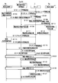
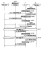
- FIG. 10 and FIG. 11 are sequence diagrams showing the procedure of biological transportation using the biological transportation support system 9.
- the root side of the arrow represents the subject of the implementation content
- the tip side of the arrow represents the object of the implementation content.
- the administrator of the server 7 examines those who wish to use and, if there is no problem, registers each user information in the user information DB 108 of the server 7 (S104).
- User information includes a user name, location, telephone number, FAX number, person in charge, etc., and is registered in correspondence with the user ID (login user name) uniquely assigned to each user by the control means 101.
- the Furthermore, each user information is set with an arbitrary user password.
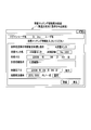
- the shipping source 4 such as the hospital 1 displays the transport / culture instruction information input screen as shown in FIG. 12 created by the display creating unit 104 from the shipping source terminal 4a. Through the communication line 6 and the communication means 106.
- the shipping terminal 4a displays a transportation / culture instruction information input screen as shown in FIG. 12, and the shipping source 4 is prompted by the message “Please enter transportation / culture instruction information” to transport In the text box corresponding to “Sample Low Temperature Storage Container Transport Delivery Location” displayed in the culture instruction information input area, “A Hospital Internal Medicine” or the like can be accurately input as the delivery location.
- the “delivery date” that can be prepared by the shipping source 4 the “number of containers” of the containers containing living organisms, the “sample details” that is the ID of the container containing living organisms, and the “transportation destination” indicating the shipping destination ⁇ Returning source ”,“ Preferred arrival date ”when the container containing the living body arrives at the transportation destination,“ Sample culture condition ”,“ Preferred date for receiving completed culture ”requested by the hospital to the culture center.
- a list box is listed.
- the desired transportation consignment price, culture consignment price, etc. may be entered and input as transport / culture instruction information.
- the shipping source terminal 4a provides support that the shipping source 4 can easily create the transportation / culture instruction information (S105) by filling in the instruction contents in the text box and the list box.
- the shipping source terminal 4a transmits the transport / culture instruction information to the receiving means 113 of the server 7 via the communication line 6 (S106).
- the registration means 103 of the server 7 registers the received transportation / culture instruction information in the shipping source information DB 109 (S107).
- the shipping source 4 clicks the “Register” button. If you want to cancel the creation of the shipping / culture instruction information, click the “Back” button.
- the control means 101 of the server 7 reads the transportation / culture instruction information from the shipping source information DB 109 and uses the transmission means 114 to transmit the transportation / culture instruction information via the communication line 6 to a plurality of registered transportation / culture instruction information.
- the information is transmitted to the trader terminal 2a and the shipping destination terminal 5a of the A culture center (shipping destination) designated as the transport destination in the transport / culture instruction information (S108).
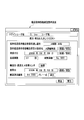
- the transporter terminal 2a Upon receipt of the transportation / culture instruction information, the transporter terminal 2a sends the communication line 6 and the communication means to the control means 101 so as to display the transportation commission information input screen as shown in FIG. Request via 106.
- the transportation contractor information input screen as shown in FIG. 13 is displayed on the transporter terminal 2a, and the transporter 2 is urged to display “Please enter transport consignment information” to display the transport consignment information input area.
- “A transportation logistics” or the like can be accurately input as the trader name.
- the “receivable date” that can be changed with respect to the date designated by the sender 4 based on the transportation / culture instruction information, the “number of containers” based on the transportation / culture instruction information, and the transportation / culture instruction information.
- “delivery destination” based on the transport destination / return source of transport / culture instruction information
- "delivery date” that can be changed with respect to the date based on the desired arrival date of transport / culture instruction information
- “Transportation cost price” which is an estimated amount of the carrier 2, a text box and a list box corresponding to each are described.
- the transporter terminal 2a provides support (S109) that the transport contractor 2 can easily create transport consignment information by allowing the transporter 2 to fill the consignment contents in the text box and the list box.
- the transporter terminal 2a transmits transport consignment information to the receiving means 113 of the server 7 via the communication line 6 (S111).
- the registration means 103 of the server 7 registers the received transportation consignment information in the contract information DB 110.
- the transporter 2 clicks the “Register” button.
- the “return” button is clicked.
- the shipping destination terminal 5a Upon receipt of the transport / culture instruction information, the shipping destination terminal 5a sends the communication line 6 and the communication line to the control means 101 so as to display the culture acceptance information input screen as shown in FIG. Request via means 106. As shown in FIG. 14, a culture commission information input screen as shown in FIG. 14 is displayed on the shipping destination terminal 5 a, and the shipping destination 5 is prompted by the message “Please enter culture commission information”. In the text box corresponding to “Culture Center Name” displayed in the box, “A Culture Center” or the like can be accurately input as the culture center name.
- the “receivable date” that can be changed with respect to the date designated by the sender 4 based on the transportation / culture instruction information
- “Culture completion body delivery date” that can be changed with respect to the date based on the desired date of receipt of the culture completion body in the transportation / culture instruction information
- “Culture business price” that is the estimated amount of the culture center 3
- texts corresponding to each Boxes and list boxes are listed.
- the shipping destination terminal 5a provides support (S110) that the culture destination information can be easily created by causing the shipping destination 5 to fill the culture contents in the text box and the list box.
- the shipping destination terminal 5a transmits the culture consignment information to the receiving means 113 of the server 7 via the communication line 6 (S112).
- the registration means 103 of the server 7 registers the received culture commission information in the contract information DB 110.
- the shipping destination 5 clicks the “Register” button. If you want to cancel the creation of the contracted culture information, click the “Back” button.
- the matching means 102 of the server 7 includes the shipping / culture instruction information, the transportation contract information, and the like, for example, various schedules of the registered shipping / culture instruction information, transport contract information, and culture contract information are matched.
- the culture contract information is extracted, matching information (including transport matching information and culture matching information) is created using various matched schedules, and registered in the matching information DB 111.
- the display creation means 104 composes and creates a transport matching information display screen as shown in FIG. 15 based on the transport matching information, and the control means 101 transmits to the shipping source terminal 4a using the transmission means 114 ( S113).
- a shipping matching information display screen as shown in FIG. 15 is displayed on the shipping source terminal 4a, and the shipping source 4 is prompted to display “Please enter shipping matching information” and needs to be changed.
- the transport matching information is confirmed, and the contract instruction information is created (S114) at the shipping source terminal 4a and transmitted to the server 7. (S115).
- the content of the transport matching information becomes the content of the transport contract between the shipping source 4 and the transporter 2.
- step S116 the display creation means 104 configures and creates a culture matching information display screen as shown in FIG. 16 based on the culture matching information, and the control means 101 uses the transmission means 114 to send it out. It transmits to the former terminal 4a.
- a culture matching information display screen as shown in FIG. 16 is displayed on the shipping source terminal 4 a, and the shipping source 4 is prompted to enter “culture matching information” and needs to be changed. In this case, by clicking the “presentation” button, it is possible to input “culture completion date” and “culture order price” by changing the descriptions in the corresponding text boxes.
- the culture matching information is confirmed (S116), and the contract instruction information is created and transmitted to the server 7 at the shipping source terminal 4a.
- the content of the culture matching information is the content of the culture contract between the shipping source 4 and the shipping destination 5.
- the correction means 105 of the server 7 determines the appropriateness of the change content. If the change content is appropriate, the change content is used as matching information. If not, the change content is deleted / changed. The matching information is corrected so as to be within an appropriate range, and the corrected matching information is registered in the matching information DB 111, thereby confirming the contract contents (matching information).
- step S116 the display creating unit 104 configures and creates a transport request information confirmation display screen as shown in FIG. 17 based on the transport matching information of the matching information determined.
- the control unit 101 uses the transmission unit 114. Then, the information is transmitted to the shipping source terminal 4a and the transporter terminal 2a, and support for concluding a so-called transport culture contract is performed (S117). As a result of the transmission, a shipping request information confirmation display screen as shown in FIG. 17 is displayed on the shipping source terminal 4a, and the shipping source 4 is prompted to display “Please enter an order / order”. By clicking the “Order” button, an order signal is transmitted from the shipping source terminal 4a to the server 7, and an order can be placed as a contract.
- a transport request information confirmation display screen as shown in FIG. 17 is also displayed on the transporter terminal 2a, and the transporter 2 is prompted by the message “Please enter order / order received”.
- an order signal is transmitted from the carrier terminal 2a to the server 7 (S118), and an order as a contract can be made.
- the server 7 receives the order signal and the order signal, it can be considered that the transportation contract has been established.
- the display creation means 104 configures and creates a culture request information confirmation display screen as shown in FIG. 18 based on the culture matching information of the confirmed matching information, and the control means 101 uses the transmission means 114 to The data is transmitted to the shipping source terminal 4a and the shipping destination terminal 5a.
- a culture request information confirmation display screen as shown in FIG. 18 is displayed on the shipping source terminal 4a, and the shipping source 4 is prompted to display “Please enter order / order”.
- an order signal is transmitted from the shipping source terminal 4a to the server 7 (S119), and an order as a contract can be placed.
- a culture request information confirmation display screen as shown in FIG.
- the display creating means 104 composes and creates a quality information upon receipt of goods and transport consignment information display screen as shown in FIG. 19 based on the transport matching information of the matching information for which the contract has been established on the day of transport, and the control means 101 Transmits to the shipping source terminal 4a, the carrier terminal 2a, and the shipping destination terminal 5a using the transmitting means 114.
- the shipping source terminal 4a, the transporter terminal 2a, and the shipping destination terminal 5a display the quality information upon receipt of goods and the transport consignment information display screen.
- the shipping element 4 and the transporter 2 are prompted by the message “Please enter the quality information at the time of receipt (please carry out the inspection)”, and the detection element 18 for detecting contaminants such as bacteria that have entered.
- step S121 it is checked whether or not the site is contaminated with bacteria.
- the inspection is performed by the transporter 2 or the shipping source 4 using the inspection devices 30, 30a, 30b.
- the inspection result is transmitted from the inspection devices 30, 30 a and 30 b to the server 7 via the communication line 6.
- the inspection result is stored in the quality information DB 112 of the storage unit 115.
- the inspection result is transmitted by the control means 101 to the shipping source terminal 4a, the carrier terminal 2a, and the shipping destination terminal 5a by using the transmission means 114.
- the shipping source terminal 4a, the transporter terminal 2a, and the shipping destination terminal 5a display the inspection result as the quality grade and the bacterial mass in the “sample quality” on the quality information at the time of receipt of goods and the transport consignment information display screen.
- the “confirm” button corresponding to each of the quality grade and the mass of bacteria is clicked by the shipping source 4, the transporter 2, and the shipping destination 5 on each of the shipping source terminal 4a, the transporter terminal 2a, and the shipping destination terminal 5a.
- the quality assurance signal is transmitted to the server 7.
- the control means 101 of the server 7 displays “guaranteed” on the quality information at the time of receipt of goods and the transportation consignment information display screen.
- the carrier 2 can transport the storage container 100, click the “consignment” button, receive the storage container 100 from the shipping source 4, and start transporting. (S121).
- the sample low-temperature storage transport container ID is input from the shipping source terminal 4a or the transporter terminal 2a, transmitted to the server 7, and registered in the matching information DB 111 in association with the sample details that are the ID of the living body.
- the dedicated terminal 8 of the storage container 100 measures the date and time (month / day / hour / minute) with a built-in timer, measures the moving point (position) with the built-in GPS, and is built in.
- the temperature at the time of transportation is measured with a thermometer, the container temperature measured by the temperature measuring element 67 of the storage container 100 is received using the receiving means 8a, and the acceleration measured by the accelerometer of the storage container 100 is received by the receiving means 8a.
- the ID of the storage container 100 is received from the storage container 100.
- the dedicated terminal 8 stores the date and time (month / day / hour / minute), moving point (position), air temperature, container temperature, acceleration, and ID of the storage container 100 as transport environment information in the storage unit 8c. It transmits to the server 7 using the transmission means 8b (S122). Measurement, reception, and transmission are repeatedly performed at predetermined time intervals. Moreover, when measured values, such as container temperature, exceed a predetermined threshold value, you may receive and transmit the measured value with the date and time measured simultaneously.
- the server 7 receives the transport environment information using the receiving unit 113.
- the registration unit 103 of the server 7 registers the transportation environment information in the quality information DB 112 (S123).
- the display creation means 104 of the server 7 configures and creates a transportation environment information display screen as shown in FIG. 20 based on the transportation environment information.
- the control unit 101 uses the transmission unit 114 to display the transport environment information display screen, the shipping source terminal 4a, the transporter terminal 2a, It transmits to the shipping destination terminal 5a. As a result of the transmission, a shipping environment information display screen as shown in FIG.
- the control means 101 of the server 7 extracts the ID of the storage container 100 actually associated with the received sample details using the matching information DB 111 and associates it with the extracted ID of the storage container 100.
- the transport environment information (date (month / day / hour / minute), moving point (position), air temperature, container temperature, acceleration) is extracted, and the shipping terminal 4a with the input of sample details (ID), transport The information is transmitted to the trader terminal 2a and the shipping destination terminal 5a (S124).
- the shipping source terminal 4a, the transporter terminal 2a, and the shipping destination terminal 5a receive the transport environment information and display it on the transport environment information display screen as shown in FIG.
- the shipping source 4, the transporter 2 and the shipping destination 5 can view the transport environment information on the respective terminals 4a, 2a and 5a, so-called information can be shared, and the living body from the transporter 2 to the shipping destination 5 described later can be shared.
- FIG. 20 has been described as the PUSH type, a PULL type display corresponding to a request from the shipping source terminal 4a, the carrier terminal 2a, and the shipping destination terminal 5a may be used.
- the display creation means 104 configures the unloading quality information and receipt / acceptance screen as shown in FIG. 21 on the day of the delivery date to the shipping destination 5 based on the transport matching information of the matching information for which the contract has been established.
- the control unit 101 uses the transmission unit 114 to transmit to the shipping source terminal 4a, the carrier terminal 2a, and the shipping destination terminal 5a.
- the quality grade of the sample quality is stored in the storage means 115 of the server 7 via the shipping source terminal 4a by the shipping source 4 such as the A culture center before the delivery date.
- the shipping source terminal 4a, the carrier terminal 2a, and the shipping destination terminal 5a display unloading quality information and a receipt inspection screen.
- the carrier 2 and the shipping destination 5 are prompted by the message “Please enter quality information at the time of shipment (please carry out the inspection)”, so that the invading bacteria etc.
- the detection element 18 for detecting the pollutant checks whether or not it is contaminated with bacteria on site (S125).
- the inspection is performed by the carrier 2 or the shipping destination 5 using the inspection devices 30, 30b, 30c.
- the inspection results are transmitted from the inspection devices 30, 30 b and 30 c to the server 7 via the communication line 6.
- the inspection result is stored in the quality information DB 112 of the storage unit 115.
- the inspection result is transmitted by the control means 101 to the shipping source terminal 4a, the carrier terminal 2a, and the shipping destination terminal 5a by using the transmission means 114.
- the shipping source terminal 4a, the transporter terminal 2a, and the shipping destination terminal 5a display the inspection result as the quality grade and the bacterial mass in the “sample quality” on the quality information at the time of unloading and the receipt inspection screen.
- the “confirm” button corresponding to each of the quality grade and the mass of bacteria is clicked by the shipping source 4, the transporter 2, and the shipping destination 5 on each of the shipping source terminal 4a, the transporter terminal 2a, and the shipping destination terminal 5a.
- the quality assurance signal is transmitted to the server 7.
- the sample cryopreservation container receipt / inspector belonging to the shipping destination 5 inputs the name in the corresponding text box, and clicks the “confirm” button to indicate that the inspection has been completed.
- the inputted name is transmitted from the destination terminal 5a to the server 7 (S126) and registered in the quality information DB 112 of the server 7 (S127). Further, the name is transmitted from the server 7 to the shipping source terminal 4a and the carrier terminal 2a (S130), and is displayed as a sample cryopreservation container receiving inspector on the unloading quality information and the receiving inspection screen.
- the control means 101 of the server 7 displays “guaranteed” on the quality information at the time of unloading and the receipt / acceptance screen based on the reception record of the quality assurance signal.
- the shipping destination 5 can accept the storage container 100, click the “consignment” button, receive the storage container 100 from the carrier 2, and perform the culture operation. Start (S125).
- the transportation business of the transportation company 2 ends.
- the display creation means 104 of the server 7 configures and creates a culture environment information display screen as shown in FIG.
- the control means 101 transmits the culture environment information display screen to the shipping destination terminal 5a using the transmission means 114.
- a culture environment information display screen as shown in FIG. 22 is displayed on the shipping destination terminal 5a, and the shipping destination 5 (the culture center 3) displays “Enter culture environment information / Enter sample details (ID)”. Please enter the biological sample details (ID) in the sample details text box, and the date and time (month / day / hour / minute) in the tabular text box of the culture environment information.
- Sample No. Culture condition no.
- the shipping destination terminal 5a provides support that the culture environment information can be easily created by causing the shipping destination 5 (the culture center 3) to write the state of the culture in the text box.
- the shipping destination 5 (culture center 3) clicks the “Register” button the culture environment information is determined and transmitted from the shipping destination terminal 5a to the server 7 together with the sample details (S201 in FIG. 11).
- the registration means 103 of the server 7 registers the culture environment information and the sample details in the quality information DB 112 (S202).
- the control unit 101 of the server 7 transmits the culture environment information display screen, the culture environment information, and the sample details as shown in FIG. 22 to the shipping source terminal 4a and the carrier terminal 2a using the transmission unit 114. (S203).
- a culture environment information display screen as shown in FIG. 22 is displayed on the shipping source terminal 4a and the carrier terminal 2a. Further, the shipping source terminal 4a and the transporter terminal 2a display the received culture environment information and sample details on the culture environment information display screen.
- the shipping source 4 and the transporter 2 can browse the culture environment information at the shipping source terminal 4a and the transporter terminal 2a, and can share so-called information with the shipping destination 5.
- the display creation means 104 composes and creates a culture completion information screen as shown in FIG. 23 based on the matching information registered in the matching information DB 111 on the day of the scheduled culture completion date (culture completion date).
- the control means 101 uses the transmission means 114 to transmit to the shipping destination terminal 5a.
- the shipping destination terminal 5a displays a culture completion information screen.
- the shipping destination 5 (the culture center 3) is prompted by the message “Please input culture completion information” and checks whether the cultured organism is contaminated with bacteria. Do. This inspection is performed before being stored in the storage container 100. The result of the inspection is input by the delivery destination 5 (culture center 3) into the text box for the quality grade and the mass of bacteria in “Sample culture quality” on the culture completion information screen.
- the result of the inspection is transmitted from the shipping destination terminal 5a to the server 7 via the communication line 6.
- the inspection result is stored in the quality information DB 112 of the storage unit 115.
- inspection is transmitted to the shipping origin terminal 4a, the carrier terminal 2a, and the shipping destination terminal 5a by the control means 101 using the transmission means 114 with the culture completion information screen as shown in FIG.
- the shipping source terminal 4a, the transporter terminal 2a, and the shipping destination terminal 5a display the result of the inspection as the quality grade and the bacterial mass in the “sample culture body quality” on the culture completion information screen.
- the “confirm” button corresponding to each of the quality grade and the mass of bacteria is clicked by the shipping source 4, the transporter 2, and the shipping destination 5 on each of the shipping source terminal 4a, the transporter terminal 2a, and the shipping destination terminal 5a.
- the quality assurance signal is transmitted to the server 7.
- the shipping source 4, the carrier 2, and the shipping destination 5 can mutually guarantee the quality of the living body. Ensuring the quality of living organisms is very important when receiving and receiving a sample of biological samples that are prone to deterioration.
- a sample culture body quality inspection confirmer belonging to the shipping destination 5 inputs a name in a corresponding text box, and clicks a “confirm” button to indicate that the inspection has passed.
- the inputted name is transmitted from the destination terminal 5a to the server 7 (S204) and registered in the quality information DB 112 of the server 7 (S205). Further, the name is transmitted from the server 7 to the shipping source terminal 4a and the carrier terminal 2a (S206), and is displayed as a sample culture body quality inspection confirmer on the culture completion information screen.
- the display creation means 104 uses the matching information registered in the matching information DB 111 to construct a return (transport) request information confirmation display screen as shown in FIG. create. Since the current transport is to be sent back to the previous shipping destination, the sample low temperature storage transport container delivery location can be specified to the A culture center which is the shipping destination 5 of the previous transport. Further, the transportation destination can be specified in the internal medicine of hospital A that is the shipping source 4 of the previous transportation. The name of the sample low-temperature storage container transport consignee can be specified as the A transport logistics of the transporter 2 who has a proven record in the previous transport.
- the receiving date can be set to the scheduled date of completion of culture (culture completion date) stored in the quality information DB.
- the unloading date can be the date when the number of days required for the previous transportation is added to the receiving date.
- the transportation order price can be set equal to the transportation cost price of the previous transportation.
- the sample details can be set the same as the sample details of the previous transport.
- the return (transportation) request information (so-called matching information) on the return (transportation) request information confirmation display screen thus created by the display creation means 104 is registered in the matching information DB 111 (S207).
- the return (transportation) request information confirmation display screen is transmitted from the server 7 to the shipping source terminal 4a, the transporter terminal 2a, and the shipping destination terminal 5a (S208).
- the shipping source terminal 4a, the transporter terminal 2a, and the shipping destination terminal 5a display a return (transport) request information confirmation display screen.
- the shipping source 4, the transporter 2 and the shipping destination 5 (culture center 3) are prompted by the message “Please enter the change of the return (transport) request information”, and the return (transport) request information is defective. In this case, the delivery date, transport order price, etc. can be changed from the text box. Even if there is no change, by clicking the “Register” button, return (transportation) request information (matching information) is transmitted to the server 7 (S209).
- the correction means 105 of the server 7 determines the appropriateness of the change content. If the change content is appropriate, the change content is used as matching information. If not, the change content is deleted / changed. The matching information is corrected so as to be within an appropriate range, and the corrected matching information is registered in the matching information DB 111, thereby confirming the contract contents (matching information). The order of the carrier 2 is confirmed.
- the display creation means 104 configures and creates a display screen for quality information upon receipt of goods and transportation consignment information as shown in FIG. 25 based on the matching information determined on the day of the receipt date, and the control means 101 transmits the transmission means 114.
- the control means 101 transmits the transmission means 114.
- the shipping source terminal 4a, the transporter terminal 2a, and the shipping destination terminal 5a display the quality information upon receipt of goods and the transport consignment information display screen.
- step S121 it is checked whether or not the site is contaminated with bacteria.
- the inspection can be performed in the same manner as the inspection (S121) described with reference to FIG. 19 of the previous transportation (inspection / transport processing).
- the current transportation environment information processing can also be performed in the same manner as the processing described in the previous transportation (transportation environment information processing).
- transportation environment information is transmitted from the dedicated terminal 8 to the server 7 (S122), and the registration means 103 of the server 7 registers the transportation environment information in the quality information DB 112 (S123).
- the display creation means 104 of the server 7 configures and creates a transport environment information display screen as shown in FIG. 26 based on the transport environment information.
- the control unit 101 uses the transmission unit 114 to display the transport environment information display screen, the shipping source terminal 4a, the transporter terminal 2a, It transmits to the shipping destination terminal 5a.
- a transportation environment information display screen as shown in FIG. 26 is displayed on the shipping source terminal 4a, the transporter terminal 2a, and the shipping destination terminal 5a.
- the following transportation environment information processing (S124 and the like) can be performed in the same manner as the processing described with reference to FIG. 20 of the previous transportation (transportation environment information processing).
- the display creation means 104 configures and creates the unloading quality information and receipt acceptance screen as shown in FIG. 27 based on the matching information on the day of the delivery date to the shipping source 4 which is the return destination, and performs control.
- the means 101 uses the transmission means 114 to transmit to the shipping source terminal 4a, the carrier terminal 2a and the shipping destination terminal 5a.
- the shipping source terminal 4a, the carrier terminal 2a, and the shipping destination terminal 5a display unloading quality information and a receipt inspection screen.
- the reception / acceptance process (S125 to S127, S130) at the return shipping destination can be performed in the same manner as the process described with reference to FIG. 21 of the previous transport ((reception / acceptance process at the transport destination)). . Then, the transportation service of the carrier 2 ends.
- the living body transportation support system 9 has a structure in which the sample stored in the storage container 100 is cooled and held by the refrigerator, and is chemically treated, for example, by the attachment of contaminants to the room temperature region in the storage container 100.
- the detection element 18 whose characteristics or physical characteristics change and inspecting the detection element 18 from the outside of the storage container 100 in a non-contact manner, the presence or absence of contaminants entering the storage container 100 is determined. Since the inspection is performed in a short time at the time of delivery and the data can be shared by at least the sample shipping source 4, the transporter 2 and the shipping destination 5, these three parties are responsible for the health of the sample when the sample is received and delivered. Sex can be accepted. Therefore, there is an effect that it is possible to carry out a commercial transaction using the biological transportation based on the soundness of the sample as a service (service).
- the present invention is a sample cryopreservation container for transporting or storing samples such as cells, microorganisms and proteins used in regenerative medicine, biochemical research, drug development, medical diagnosis, food inspection, etc. Is preferred.
- the present invention is also suitable as a transportation transaction support system using the sample cryogenic storage container.
- Biological transportation support system 11 Storage Container (container) 12 Opening 13 Introduction container (introduction means) 14 Lid member (blocking means) 15 Stirling refrigerator (cooling means) 16 Insulated container (insulation means) 17 Detection element holding member (detection means) 18 sensing element 19 window 21 guide tray (atmospheric induction guide) 22 Concavity (detection element placement part) 25 Metal particles 26 Biomolecules, etc.
Landscapes
- Health & Medical Sciences (AREA)
- Life Sciences & Earth Sciences (AREA)
- Clinical Laboratory Science (AREA)
- Chemical & Material Sciences (AREA)
- General Health & Medical Sciences (AREA)
- Wood Science & Technology (AREA)
- Zoology (AREA)
- Environmental Sciences (AREA)
- Engineering & Computer Science (AREA)
- Dentistry (AREA)
- Chemical Kinetics & Catalysis (AREA)
- Sampling And Sample Adjustment (AREA)
- Automatic Analysis And Handling Materials Therefor (AREA)
- Warehouses Or Storage Devices (AREA)
- Devices That Are Associated With Refrigeration Equipment (AREA)
- Devices For Use In Laboratory Experiments (AREA)
- Apparatus Associated With Microorganisms And Enzymes (AREA)
- Packages (AREA)
Abstract
液体窒素等の昇華または蒸発する冷媒を用いず、試料の受領者が試料の健全性を受領時に容易に確認することができる試料低温保存容器と、それを使用した輸送取引支援システムを提供する。保存容器100は、格納容器11に格納された試料容器Sをスターリング冷凍機15によって冷却保持する構造を有する。保存容器100内の室温域に汚染物質の付着によって化学的特性または物理的特性が変化する検知素子18を配置し、保存容器100の外部から非接触的に検知素子18を検査することにより、保存容器100の内部への汚染物質の侵入の有無を検査することを可能とした。さらに、その検査結果を検査装置30から受信して記憶し、輸送元が操作可能な端末、輸送業者が操作可能な端末および、輸送先が操作可能な端末のうちの少なくとも2つの端末に通信回線を介して接続して検査結果を送信するサーバを有する。
Description
本発明は、試料の低温輸送や低温貯蔵に用いられる試料低温保存容器、および、これを用いた生体輸送支援システムに関する。
一般に細胞や微生物、蛋白質等の有機物質(以下「試料」という)を、所定の保管場所(以下「A地点」とする)から他の利用場所(以下「B地点」とする)に輸送する場合には、輸送中の試料の品質の劣化を防ぐために、試料は低温に維持された状態で輸送される。このような用途に用いられる試料低温保存容器としては、真空断熱容器内に冷媒としての液体窒素を充填し、この液体窒素によって試料を保冷する構造のものが知られている。
このような試料低温保存容器を用いる場合、A地点において、発送者は、容器内部に液体窒素を注入した後、試料を収容する。こうして試料は-196℃近傍に保持された状態で車両等によりB地点へ輸送される。B地点において、試料は、受領者に引き取られた後、例えば、-140℃以下に保持された冷凍庫に貯蔵される。
冷媒として液体窒素を用いる場合、容器内は絶えず発生する冷媒の蒸発ガスによって、外気圧よりも高い正圧となる。そのため、逆に容器の破裂を防止するために、試料低温保存容器は、その内圧が一定となるように、蒸発ガスが外部に漏れる構造となっている。こうして、試料低温保存容器の内部から外部に蒸発ガスが漏洩し続けることで、細菌等の汚染物質が試料低温保存容器の内部に侵入することが防止され、試料の品質の保持が可能となる。このように、試料の品質が輸送中に劣化したり、汚染されたりしていないことが保証されていること、つまり、A地点での出荷時の状態がB地点においても維持されていることが保証されていることは、受領者にとっては極めて重要である。
しかし、ドライアイスや液体窒素等の昇華または蒸発する冷媒を使用する試料低温保存容器では、蒸発ガスによって酸欠状態が生じるおそれがあり、また、容器転倒や破損による冷媒流出や異常蒸発のおそれがある。そのため、このような試料低温保存容器を気密性の高い航空機の客室等や乗用車の車内に持ち込んで輸送することは一般的には行うことができず、特別な措置(例えば、転倒防止仕立ての輸送カーゴを用いて乗客と別室の輸送室に格納して輸送する等)が必要となる。このような方法には輸送コストが嵩むという問題がある。
そこで、液体窒素等の昇華または蒸発する冷媒を用いずに試料を冷凍保存することができる試料低温保存容器として、冷凍機を用いて試料を-140℃以下に冷却保持することができ、試料容器(マイクロプレート)の保冷チャンバに対する搬入出を、保冷チャンバ内に外気が流入したり、保冷チャンバ内の冷気が外部に流出したりすることなく、容易に行うことができる構造を有する保管装置が提案されている(例えば、特許文献1参照)。より具体的には、外部から試料容器を保管装置へ収容する場合には、まず、試料容器を保管装置内に設けられた前室に収容する。このとき、前室と保冷チャンバとは隔離されている。前室と外部とを遮断した後に、前室と保冷チャンバとの間に設けられている内扉を開いて、前室から保冷チャンバへ試料容器を機械搬送し、その後、内扉を閉める。試料容器を保冷チャンバから外部に搬出する場合には、これと逆の操作が行われる。
しかしながら、特許文献1に開示された保管装置では、マイクロプレートを前室に対して搬入出する際に、前室に大気中の汚染物質である細菌が入り込み、試料たる微生物や細胞等の生体に細菌が付着して、試料が汚染されたり変質したりするおそれがある。そのため、この保管装置を用いて試料を輸送する場合、受領者は試料の健全性を受領時に確認できないという問題がある。
本発明はかかる事情に鑑みてなされたものであり、液体窒素等の昇華または蒸発する冷媒を用いず、試料の受領者が試料の健全性を受領時に容易に確認することができる試料低温保存容器を提供することを目的とする。
また、本発明に係る試料低温保存容器を用いても、試料(生体)をA地点からB地点へ輸送する際、試料の品質が輸送中に劣化したり、汚染されたりしていないこと(健全性)が保証されていること、つまり、A地点での出荷時の状態がB地点においても維持されていることが保証されていることは、B地点の受領者にとっては極めて重要である。
特に、A地点の病院の患者自身の例えば皮膚細胞を、B地点の培養センタに輸送し、培養センタで作った人工多機能性幹(iPS)細胞を、再びA地点の病院に輸送し、患者の治療に使用する場合、往路、復路、それぞれの輸送完了時において、皮膚細胞やiPS細胞等の細胞の、汚染、特に細菌の混入による汚染が無いこと(健全性)を保証することは極めて重要である。
例えば、往路においては、培養前の輸送完了時に、万が一、汚染無しの保証がされず、汚染されていることがわかれば、培養を行うことなく、例えば、再度A地点の病院から試料を発送する処理を行うことができる。
本発明はかかる事情に鑑みてなされたものであり、試料(生体)に汚染が無いこと(健全性)を保証可能な生体輸送支援システムを提供することを目的とする。
本発明はかかる事情に鑑みてなされたものであり、試料(生体)に汚染が無いこと(健全性)を保証可能な生体輸送支援システムを提供することを目的とする。
本発明に係る試料低温保存容器は、格納容器に格納された試料を冷凍機によって冷却保持する構造を有し、試料低温保存容器内の室温域に汚染物質の付着によって化学的特性または物理的特性が変化する検知素子を配置し、試料低温保存容器の外部から非接触的に検知素子を検査することにより、試料低温保存容器の内部への汚染物質の侵入の有無を検査することができるものである。
また、本発明に係る生体輸送支援システムは、前記試料低温保存容器の内部への汚染物質の侵入の有無の検査の検査結果を記憶する記憶手段と、前記試料の輸送元が操作可能な第1端末、前記試料の輸送業者が操作可能な第2端末および、前記試料の輸送先が操作可能な第3端末のうちの少なくとも2つの端末に、通信回線を介して接続して前記検査結果を送信する通信手段とを有することを特徴とするものである。
本発明によれば、試料の受領者は、試料の健全性を受領時に容易に確認することができる試料低温保存容器を提供できる。
また、本発明によれば、試料(生体)に汚染が無いこと(健全性)を保証可能な生体輸送支援システムを提供できる。
また、本発明によれば、試料(生体)に汚染が無いこと(健全性)を保証可能な生体輸送支援システムを提供できる。
以下、図面を参照しながら本発明の実施の形態について詳細に説明する。
《第1実施形態》
<試料低温保存容器の全体構造>
図1に本発明の一実施形態に係る試料低温保存容器(以下「保存容器」という)100の概略構造を表した断面図を示す。この保存容器100は、概略、被冷却体(試料)が収納された試料容器Sを格納する格納容器11(格納手段)と、格納容器11に取り付けられ、試料容器Sを格納容器11に対して出し入れするための開口12を備えた導入容器13(試料導入手段)と、導入容器13の開口12を閉塞する蓋部材14(閉塞手段)と、格納容器11に格納された試料容器Sを冷却するスターリング冷凍機15(寒冷発生手段)と、格納容器11とスターリング冷凍機15とを収容すると共に、格納容器11とスターリング冷凍機15への外部からの熱の伝達を抑制する断熱容器16(断熱手段)と、を備えている。
《第1実施形態》
<試料低温保存容器の全体構造>
図1に本発明の一実施形態に係る試料低温保存容器(以下「保存容器」という)100の概略構造を表した断面図を示す。この保存容器100は、概略、被冷却体(試料)が収納された試料容器Sを格納する格納容器11(格納手段)と、格納容器11に取り付けられ、試料容器Sを格納容器11に対して出し入れするための開口12を備えた導入容器13(試料導入手段)と、導入容器13の開口12を閉塞する蓋部材14(閉塞手段)と、格納容器11に格納された試料容器Sを冷却するスターリング冷凍機15(寒冷発生手段)と、格納容器11とスターリング冷凍機15とを収容すると共に、格納容器11とスターリング冷凍機15への外部からの熱の伝達を抑制する断熱容器16(断熱手段)と、を備えている。
また、保存容器100では、格納容器11へ侵入した汚染物質を検知するための検知素子18を保持する検知素子保持部材17(検知手段)が、導入容器13の開口12近傍に設けられており、検知素子18の汚染物質との反応の有無を、蓋部材14が導入容器13の開口12を閉塞している状態において蓋部材14の外側から検査することができるように、蓋部材14に窓部19が設けられている。以下、各構成要素について説明するが、説明の順番は前記した符号の順番とは必ずしも一致しない。
<格納手段>
格納容器11は熱伝導率の大きな材料からなり、例えば、アルミニウムや銅が好適に用いられる。格納容器11は、その上面で開口している複数の穴部61を備えており、各穴部61に試料容器Sを収容することができるようになっている。格納容器11は、その下面にネジ部62を備えている。
格納容器11は熱伝導率の大きな材料からなり、例えば、アルミニウムや銅が好適に用いられる。格納容器11は、その上面で開口している複数の穴部61を備えており、各穴部61に試料容器Sを収容することができるようになっている。格納容器11は、その下面にネジ部62を備えている。
格納容器11を断熱容器16内において固定するための支持台63が、略円筒形状の支持筒64の上部に取り付けられており、この支持筒64は、断熱容器16の下蓋65に立設されている。支持台63には、格納容器11が具備するネジ部62と螺合するネジ穴が設けられており、ネジ部62をこのネジ穴に螺合することにより、格納容器11が断熱容器16内において固定される。
支持台63はアルミニウム等の熱伝導性に優れる材料で構成されており、これにより、格納容器11と支持台63とが構造的に一体化されると共に、熱的に一体化される。なお、「格納容器11と支持台63とが熱的に一体化される」とは、格納容器11と支持台63とが実質的に同じ温度となることをいう。スターリング冷凍機15は、格納容器11と熱的に一体化された支持台63を介して格納容器11を冷却し、これにより格納容器11に格納された試料容器Sが冷却される。後記するように、スターリング冷凍機15は-140℃以下の低温を発生させることができ、試料容器Sはこのような低温に保持される。
支持筒64は、熱伝導率が小さく、格納容器11と支持台63とを機械的に安定して支持することができる機械的強度を有する材料からなり、例えば、各種の硬質プラスチック(FRPを含む)が好適に用いられる。これは、支持筒64が保持する支持台63はスターリング冷凍機15により低温とされるが、下蓋65は外気に接すると共に後記するようにスターリング冷凍機15の圧縮部73で発生する圧縮熱の放熱に用いられているために、下蓋65と支持台63との間での熱の移動が起こらないようにする必要があるためである。支持筒64の側面には、図示しない孔部が形成されており、支持筒64の内側と外側とは、同じ雰囲気(後記するように、真空雰囲気とされる)に維持される。
格納容器11には温度計測素子67が取り付けられている。この温度計測素子67はバッテリ電源(図示せず)により動作し、例えば、保存容器100の輸送中における格納容器11の温度履歴(試料容器Sの温度履歴)が、温度記録装置68に記録されるようになっている。温度記録装置68は、温度計測素子67により計測された温度をデータ化するデータ処理部(図示せず)と、データ処理部によって作成された温度データを記憶するデータ記憶部(図示せず)を備えている。
データ処理部は、所謂、マイクロコンピュータである。データ記憶部としては、例えば、温度記録装置68に対して着脱可能であると共に、パーソナルコンピュータ(PC)に対して着脱可能なメモリデバイス(例えば、SDカード等)が好適に用いられる。このようなメモリデバイスをPCに装着してこれに記憶された温度データを読み出すことにより、試料容器Sの温度履歴を容易に確認することができる。
なお、図1では温度記録装置68を断熱容器16外に示しているが、温度記録装置68は、断熱容器16に装着された構成とすることができる。温度計測素子67による格納容器11の温度計測と温度記録装置68による温度データの記憶は、手動で開始し、終了させる構成とすることができる。また、温度記録装置68に年月日及び時分秒を確認することができる時計を内蔵させ、かつ、温度データの測定と記憶がスターリング冷凍機15の駆動を開始した時に自動的に始まるようにしてもよい。不慮の事故によるスターリング冷凍機15の停止やスターリング冷凍機15を駆動する電源76(後記する)からの電力供給停止が生じても温度計測が実行されるように、温度記録装置68の動作停止は、手動で行うことができるようになっていることが好ましい。
<寒冷発生手段>
スターリング冷凍機15は、作業媒体であるヘリウム(He)ガスを圧縮し、高圧となったHeガスを断熱膨張させることで寒冷を発生し、約-140℃以下の低温を発生させることができる。スターリング冷凍機15は支持筒64内に配置されている。スターリング冷凍機15は、Heガスを圧縮する圧縮部73と、圧縮部73で発生する圧縮熱を逃がすための伝熱板74と、圧縮部73で発生させた高圧Heガスを断熱膨張させて寒冷を発生させる冷却部72と、冷却部72の寒冷を支持台63(格納容器11)に伝導する円筒状のリング75と、を備えている。
スターリング冷凍機15は、作業媒体であるヘリウム(He)ガスを圧縮し、高圧となったHeガスを断熱膨張させることで寒冷を発生し、約-140℃以下の低温を発生させることができる。スターリング冷凍機15は支持筒64内に配置されている。スターリング冷凍機15は、Heガスを圧縮する圧縮部73と、圧縮部73で発生する圧縮熱を逃がすための伝熱板74と、圧縮部73で発生させた高圧Heガスを断熱膨張させて寒冷を発生させる冷却部72と、冷却部72の寒冷を支持台63(格納容器11)に伝導する円筒状のリング75と、を備えている。
伝熱板74は断熱容器16の下蓋65に取り付けられており、伝熱板74から下蓋65に伝えられた熱は、下蓋65の表面から外部に放熱される構造となっている。そのため、伝熱板74と下蓋65には、安価で熱伝導性に優れるアルミニウムが好適に用いられる。
リング75には、熱伝導性に特に優れる銅(Cu)が好適に用いられる。冷却部72は、圧縮部73と伝熱板74とを介して下蓋65に固定されており、一方、格納容器11は、支持台63及び支持筒64によって支持されている。しかし、保存容器100に外部から振動等が加えられた際には、格納容器11と冷却部72のそれぞれの振動に振幅差と位相差が生じることが予想される。そこで、リング75を、冷却部72と支持台63とによって一定の力でその径方向に圧縮された状態とすることにより、保存容器100に外部から振動等が加えられた際には、リング75が変形(撓み変形)してリング75と格納容器11との接触及びリング75と冷却部72との接触が確保され、冷却部72と支持台63との間の熱伝導が確保される。
圧縮部73には電源76が取り付けられている。図1では電源76を断熱容器16外に示しているが、例えば、制御ユニットを、下蓋65からの放熱が妨げられないように下蓋65の下側に設け、この制御ユニット内に電源76を配置した構成とすることができる。電源76には電池が用いられ、これにより保存容器100を稼働状態で搬送することができる。電池には、例えば、ニッケル水素電池やリチウムイオン電池等の二次電池が好適に用いられる。電源76は、二次電池を容易に着脱交換できる構造となっていると共に、家庭用電源等からACアダプタを用いて充電可能な構造となっており、しかも、ACアダプタによりダイレクトに圧縮部73を駆動することも可能な構造となっている。
<試料導入手段>
導入容器13の開口12及び内部空間を通して、試料容器Sが格納容器11に対して出し入れされる。例えば、無菌室内において、液体窒素により-196℃に冷却された状態の試料容器Sが、-140℃以下に保持された格納容器11に挿入される。
導入容器13の開口12及び内部空間を通して、試料容器Sが格納容器11に対して出し入れされる。例えば、無菌室内において、液体窒素により-196℃に冷却された状態の試料容器Sが、-140℃以下に保持された格納容器11に挿入される。
断熱容器16の上面蓋部81の内周面と導入容器13の外周面との間の隙間を介して空気が断熱容器16内に侵入することがないように、導入容器13は、導入容器13の外周面がOリング82で締め付けられるようにして、フランジ83とボルト84を用いて固定されている。Oリング82は、後記するように、通常、常温近傍の温度環境で用いられる。そのため、Oリング82としては、例えば、フッ素ゴムやシリコーンゴム等の樹脂からなるものが好適に用いられる。
導入容器13の開口12近傍(上部)は、外気温とほぼ同じ温度となるが、導入容器13の格納容器11側(下部)では、前記した通りに格納容器11が-140℃近傍の低温に保持されるため、格納容器11と同等の温度となる。そのため、導入容器13には熱伝導率の小さな材料が用いられ、例えば、プラスチックが好適に用いられる。また、導入容器13の内部空間における気体の対流を防止して、導入容器13の上部から下部への熱の伝達を防止するために、発泡スチロール等の断熱材からなる対流防止体85が格納容器11側に配置されており、対流防止体85上に、導入容器13内の上部から下部への輻射熱を遮断するための積層断熱材86が配置されている。例えば、積層断熱材86としては、アルミニウム箔を束ねた構造を有するもの等が好適に用いられる。なお、対流防止体85と積層断熱材86は、断熱手段の構成要素でもある。
<閉塞手段>
導入容器13の開口12を蓋部材14により閉塞することにより、格納容器11の内部空間が大気と隔離される。蓋部材14には、金属またはプラスチックからなるものを用いることができる。蓋部材14を導入容器13に取り付けるために、蓋部材14の外周部にはOリング91の上部を収容する溝が形成されており(後記図2参照)、導入容器13の上面には、このOリング91を支持するリング部87が形成されている。そして、クランプ型の取り付け冶具92を用いて、蓋部材14の外周部と導入容器13のリング部87とを締め付けることにより、蓋部材14が導入容器13に固定される。なお、Oリング91は常温近傍の温度環境で用いられるため、Oリング91には、例えば、フッ素ゴムやシリコーンゴム等の樹脂からなるものが好適に用いられる。
導入容器13の開口12を蓋部材14により閉塞することにより、格納容器11の内部空間が大気と隔離される。蓋部材14には、金属またはプラスチックからなるものを用いることができる。蓋部材14を導入容器13に取り付けるために、蓋部材14の外周部にはOリング91の上部を収容する溝が形成されており(後記図2参照)、導入容器13の上面には、このOリング91を支持するリング部87が形成されている。そして、クランプ型の取り付け冶具92を用いて、蓋部材14の外周部と導入容器13のリング部87とを締め付けることにより、蓋部材14が導入容器13に固定される。なお、Oリング91は常温近傍の温度環境で用いられるため、Oリング91には、例えば、フッ素ゴムやシリコーンゴム等の樹脂からなるものが好適に用いられる。
蓋部材14に設けられている窓部19は、ここでは、後記するように検知素子18の光学的特性の変化を測定することができるように、石英ガラス等の透光性材料からなる。蓋部材14には、導入容器13内の圧力が高くなった場合にガス抜きを行う安全弁93が設けられている。
<断熱手段>
断熱容器16の内部は、支持筒64の内部をも含めて、真空雰囲気に保持される。断熱容器16内を真空雰囲気とするために、断熱容器16は、図示しない真空ポンプと接続するための配管部(図示せず)と開閉バルブ(図示せず)とを備えている。断熱容器16は、その内部を減圧雰囲気とした際に外圧との圧力差に耐えて形状を保持することができる機械的強度を有しており、金属またはプラスチックからなるものを用いることができる。
断熱容器16の内部は、支持筒64の内部をも含めて、真空雰囲気に保持される。断熱容器16内を真空雰囲気とするために、断熱容器16は、図示しない真空ポンプと接続するための配管部(図示せず)と開閉バルブ(図示せず)とを備えている。断熱容器16は、その内部を減圧雰囲気とした際に外圧との圧力差に耐えて形状を保持することができる機械的強度を有しており、金属またはプラスチックからなるものを用いることができる。
断熱容器16の外周は外気温度と同等となるため、断熱容器16内に設けられた低温部(冷却部72、リング75、支持台63、格納容器11)への断熱容器16の外周からの輻射熱を遮断するために、断熱容器16の内側と支持筒64の内側にそれぞれ、円筒状の積層断熱材88が配置されている。積層断熱材88は、積層断熱材86と同様に、アルミニウム箔を束ねた構造を有するもの等が好適に用いられる。
なお、断熱容器16内に残った水分や冷却部72よりも沸点の高いガスは、スターリング冷凍機15を駆動した際に、冷却部72に液体または固体として付着することで、断熱容器16内は高い真空度に保持される。
<検知手段>
図2に保存容器100の上部の構造を拡大して示すと共に、検知素子18を検査するための検査装置30の概略構成を併記する。検知素子保持部材17は、円板状のガイドトレイ21(大気誘導ガイド部)に、検知素子18を配置するための凹部22(検知素子配置部)が形成された構造を有している。図3に検知素子18及び凹部22の床面を拡大して表した断面図を示す。図3に示すように、凹部22の床面には孔部23が形成されている。
図2に保存容器100の上部の構造を拡大して示すと共に、検知素子18を検査するための検査装置30の概略構成を併記する。検知素子保持部材17は、円板状のガイドトレイ21(大気誘導ガイド部)に、検知素子18を配置するための凹部22(検知素子配置部)が形成された構造を有している。図3に検知素子18及び凹部22の床面を拡大して表した断面図を示す。図3に示すように、凹部22の床面には孔部23が形成されている。
ガイドトレイ21は導入容器13の上面(リング部87)に載置されており、導入容器13内に落下することはない形状に設計されている。ガイドトレイ21を位置決めするために、ガイドトレイ21の厚さ以下の突起部を、リング部87表面に1または複数箇所設け、このような突起部と係合する切り欠きまたは穴部をガイドトレイ21の外周部に設けてもよい。
導入容器13の内部には対流防止体85と積層断熱材86が配置されているが、導入容器13の内部の平均温度は、外部温度よりも低いために、導入容器13内は外部に対して負圧となっている。そのため、図2に示されるように、導入容器13の開口12と蓋部材14とのシール部(Oリング91によるシール部分)を介して導入容器13内へ流入する大気(空気)がある場合に、この大気は、ガイドトレイ21と蓋部材14との間に形成された空間から凹部22の方向へ誘導されて、孔部23を通過して導入容器13内へと流れ、さらに、導入容器13下部の低温部(格納容器11側)へと拡散する。
そこで、凹部22の床面上に検知素子18を配置しておけば、検知素子18は大気と接触しやすくなり、大気に細菌等の汚染物質が含まれている場合に、検知素子18と汚染物質とが反応する確率を高めることができる。これにより、汚染物質が保存容器100内に侵入した場合の検出精度、検出確率を高めて、検知素子18による検査の信頼性を高めることができるようになる。
なお、検知素子18が配置される部位の温度は、外気温とほぼ等しくなっている。このように、導入容器13内に侵入した細菌等の活動が抑制されない温度域に検知素子18を配置することで、細菌等を確実に検知素子18と反応させて、その侵入を検知することができるようになる。
また、後記するように、検知素子18の検査を光学的方法により行う場合には、結果的に、窓部19を通して観察することができる範囲に検知素子18を固定すればよい。一方、検知素子18の検査を磁気的(電磁気的)方法により外部から非接触で行う場合には、磁気センサの検出可能な範囲内に検知素子18を固定すればよい。
[検知素子]
検知素子18としては、例えば、従来の生体分子相互作用測定装置で免疫センサとして用いられており、光学系を利用した計測が可能な貴金属微粒子センサを用いることができる。すなわち、金(Au)や銀(Ag),銅(Cu),白金(Pt)等の金属微粒子センサが凹部22の床面上に固定される。なお、例えば、未反応な状態にある検知素子18が凹部22に固定された複数のガイドトレイ21を準備しておくことにより、ガイドトレイ21を交換することで、検知素子18を新しいものに容易に交換することができる。
検知素子18としては、例えば、従来の生体分子相互作用測定装置で免疫センサとして用いられており、光学系を利用した計測が可能な貴金属微粒子センサを用いることができる。すなわち、金(Au)や銀(Ag),銅(Cu),白金(Pt)等の金属微粒子センサが凹部22の床面上に固定される。なお、例えば、未反応な状態にある検知素子18が凹部22に固定された複数のガイドトレイ21を準備しておくことにより、ガイドトレイ21を交換することで、検知素子18を新しいものに容易に交換することができる。
図3に示されるように、検知素子18としての貴金属微粒子センサは、金属粒子25の上部表面に、抗体やDNA等に対して特異的な吸着能を有し、測定対象である細菌等と相互作用する化学物質または生体分子(リガンド)26(以下「生体分子等26」と記す)が固定された構造を有している。検知素子18としては、こうして生体分子等26で修飾された表面がさらに水分を有した保水性のポリマ(高分子)27で覆われた構造を有するものを用いることが好ましい。これにより、生体分子等26への細菌等の付着性能が高められる。すなわち、細菌等が水分を介して生体分子等26に容易に到達し、生体分子等26と化学結合する効率が高められて、細菌等の検出確率が向上する。こうして、試料の汚染の有無の判断に対する信頼性が向上する。
なお、導入容器13の下部にはスターリング冷凍機15により低温に保持される格納容器11が配置されているため、導入容器13内の湿度は大気に比べ低い。そのため、生体分子等26に直接に水分を含ませても、短時間で蒸発してしまうおそれがある。そこで、保水性のポリマ27によって水分の蒸発を抑制することにより、長時間にわたって生体分子等26に水分を保有させて、細菌の付着性能を維持することが可能となる。
[検査装置]
検知素子18が細菌等と反応したか否かを、保存容器100の外部から非接触で検査するための検査装置30として、ここでは、光学式の検査装置を取り上げる。図2に示されるように、検査装置30は、窓部19と対向するように配置される光ファイバヘッド33を備えている。この光ファイバヘッド33は、測定光の照射と反射光の受光とを行うことができる構造となっている。検査装置30は、光ファイバを通して光ファイバヘッド33へ測定光を送る光源31と、光ファイバヘッド33が受光した検知素子18からの反射光を、光ファイバを通して受光して分析するデータ処理装置32と、を備えている。
検知素子18が細菌等と反応したか否かを、保存容器100の外部から非接触で検査するための検査装置30として、ここでは、光学式の検査装置を取り上げる。図2に示されるように、検査装置30は、窓部19と対向するように配置される光ファイバヘッド33を備えている。この光ファイバヘッド33は、測定光の照射と反射光の受光とを行うことができる構造となっている。検査装置30は、光ファイバを通して光ファイバヘッド33へ測定光を送る光源31と、光ファイバヘッド33が受光した検知素子18からの反射光を、光ファイバを通して受光して分析するデータ処理装置32と、を備えている。
データ処理装置32の構造の詳細な図示は省略するが、データ処理装置32は、検知素子18からの反射スペクトルに基づいて検知素子18の吸収スペクトルを求める分光光度計と、分光光度計で得られた吸収スペクトルをA/D変換するA/D変換器と、A/D変換器により変換されたデジタルデータを記憶する記憶デバイスと、吸収スペクトルを表示する表示装置とを備えている。なお、A/D変換器はパーソナルコンピュータ(PC)に設けられたインターフェイスであってもよく、作成されたデジタルデータはPCに付随するハードディスク等の記憶デバイスに記憶され、得られた吸収スペクトルはパーソナルコンピュータのモニタに表示させる構成とすることができる。
このような構成により、検査装置30による検査では、まず、光源31で発生させた光が、光ファイバを通って光ファイバヘッド33に到達した後、窓部19を通して検知素子18に照射される。そして、検知素子18からの反射光は、窓部19を通して光ファイバヘッド33に受光され、光ファイバを通してデータ処理装置32内の分光光度計に到達し、そこで吸収スペクトルの計測が行われた後、得られたアナログデータがA/D変換器に送られてデジタルデータに変換され、このデジタルデータが記憶デバイスに記憶され、また、スペクトルが表示装置に表示される。
図4に検査装置により測定される吸収スペクトルを模式的に示す。検知素子18の吸収スペクトルは、検知素子18が具備する生体分子等26への細菌等の結合の度合いによって変化する。そのため、細菌等と結合しておらず、汚染されていない健全な状態にある検知素子18の吸収スペクトルは、図4中に破線で示される分光スペクトルになるが、細菌等と結合して汚染された状態にある検知素子18の吸収スペクトルは、図4中に実線で示される分光スペクトルとなり、分光スペクトルのピークシフトが生じる。こうしてデータ処理装置32で得られる吸収スペクトルのピークのずれ幅を計測することにより、細菌が生体分子等26に結合した割合を求めることができ、保存容器100(導入容器13)内の細菌等による汚染の有無を判断することができる。
《保存容器の使用形態》
試料の発送者は、発送元の無菌室で保存容器100に試料(試料容器S)を収容する。例えば、液体窒素で冷却された試料の場合には、スターリング冷凍機15を駆動して格納容器11を一定温度に下げた状態で、その試料を格納容器11に格納する。一方、常温の試料の場合には、格納容器11に格納した後にスターリング冷凍機15を駆動する。試料を格納容器11に格納した後には、対流防止体85と積層断熱材86とがセットされ、さらに汚染されていない検知素子18が固定されたガイドトレイ21が導入容器13の開口12にセットされて、蓋部材14により導入容器13の開口12が閉塞される。なお、試料が格納容器11に格納された時点から、温度計測素子67による格納容器11の温度計測を開始し、温度データを温度記録装置68に記録させる。
試料の発送者は、発送元の無菌室で保存容器100に試料(試料容器S)を収容する。例えば、液体窒素で冷却された試料の場合には、スターリング冷凍機15を駆動して格納容器11を一定温度に下げた状態で、その試料を格納容器11に格納する。一方、常温の試料の場合には、格納容器11に格納した後にスターリング冷凍機15を駆動する。試料を格納容器11に格納した後には、対流防止体85と積層断熱材86とがセットされ、さらに汚染されていない検知素子18が固定されたガイドトレイ21が導入容器13の開口12にセットされて、蓋部材14により導入容器13の開口12が閉塞される。なお、試料が格納容器11に格納された時点から、温度計測素子67による格納容器11の温度計測を開始し、温度データを温度記録装置68に記録させる。
続いて、発送者は、検査装置30を用いて検知素子18の吸収スペクトルを測定する。測定者は、得られた吸収スペクトルのデジタルデータを、例えば、インターネット等の通信手段を利用して、試料の受領者に送信する。これにより、発送者が細菌等の汚染物質に汚染されていない試料を発送したことが証明され、発送者の信頼が確保される。
保存容器100では、スターリング冷凍機15によって格納容器11が冷却されることによって、導入容器13の内部空間も冷却されて外気圧に対して負圧となる。そのため、受領者によって蓋部材14が開けられるまでの間は、導入容器13の開口12と蓋部材14との間のシール部を介して大気が導入容器13内に侵入するおそれがある。また、窓部19や安全弁93のシール部からも、大気が導入容器13内に侵入するおそれがある。
こうして、導入容器13内に大気が侵入した場合、大気はガイドトレイ21によって検知素子18が固定された凹部22へ導かれて、孔部23から導入容器13内に流れ込む。このとき、この大気内に細菌等の汚染物質が混入していれば、細菌等が検知素子18と反応して、検知素子18の光学的特性(光吸収特性)が変化する。一方、導入容器13内への細菌等の侵入がない場合には、検知素子18の光学的特性は変化しない。
ここで、試料を発送する発送元の発送者が、品質を満足し細菌等に汚染されていない試料を格納した保存容器100を、品質を満足している旨の証明書を発行し、更に輸送業者の要請により、輸送を依頼する輸送業者に渡す際に、輸送業者に検知素子18で品質を満足している旨を確認させることも可能である。また、輸送された保存容器100を受け取る受領者は、受け取りの際に、検査装置30を用いて、検知素子18の吸収スペクトルを測定し、その結果を、先に発送者から送られてきた吸収スペクトルと対比して、そのピークシフト量を調べる。その結果、ピークシフト量が、予め定められた所定値以下であれば、保存容器100に収容された試料は汚染されていないものと判断する。また、受領者は、温度記録装置68から温度データを取り出して、輸送期間中に試料が一定の低温に保持されていたか否かを確認することができる。これにより、受領者は、試料に、輸送中に保持温度が上昇することによるダメージの有無を確認することができる。このような検査結果は、パーソナルコンピュータ等を用いて迅速に行うことができ、受領者は、これらの検査結果に基づいて、保存容器100を受領するか拒否するかを決定することができる。
このように、保存容器100を用いると、試料の受領者は受領時に試料を取り出すことなく、検知素子18を迅速に検査することができる。その検査結果に異常がなければ、導入容器13の下部の細菌等が繁殖できない低温域に格納されている試料は細菌等に汚染されてないことが保証されるため、受領者は安心して保存容器100を受領し、その内部に保存された試料を使用したり、無菌室内において液体窒素等を用いた別の試料低温保存容器に移して長期保存したりすることができる。一方、検査結果に異常があれば、保存容器100の受領を拒否すると共に、検査結果を発送者へ連絡することにより、受領拒否の正当性を発送者に示すことができる。
また、受領者は、試料温度が輸送中に正規の温度に維持されていたか否かを温度記録装置68に記憶された温度データをチェックすることにより、試料が温度上昇により変質等のダメージを受けているか否かを受領前に確認することができる。この結果を試料を受領するか否かの判断基準として、検知素子18の検査結果と合わせて用いることにより、受領者は、さらに安心して試料を受領することができる。
さらに、保存容器100を用いれば、検知素子18の検査を、試料を保存容器100から取り出すことなく、非接触手段の1つである光学的方法を用いて行うことができるために、保存容器100の内部が大気に暴露されることがない。こうして、保存容器100を受領する際に保存容器100の内部に細菌等が侵入して試料が汚染される危険を回避することができるため、従来のように、後になって試料が汚染されていたことが判明した場合に、試料汚染の責任の所在がどこにあるのかを、発送者、輸送者及び受領者の間で争うことがなくなる。
《第2実施形態》
図5に本発明の第2実施形態に係る保存容器の概略構造を表した断面図を示す。図5は図2と同じ態様で示されており、図示していない部分は、図1に示した部分と同じである。この保存容器100aが第1実施形態の保存容器100と異なる点は、検知素子保持部材17として、ガイドトレイ21の表面(上面)に、殺菌手段となる酸化チタン(TiO2)等を含む触媒膜35が成膜されたものを用い、この触媒膜35に多くの紫外線(自然光または照明光のいずれであってもよい)が照射されるように、石英ガラス等からなる窓部19をその開口面積を広くして蓋部材14に設けた点にある。
図5に本発明の第2実施形態に係る保存容器の概略構造を表した断面図を示す。図5は図2と同じ態様で示されており、図示していない部分は、図1に示した部分と同じである。この保存容器100aが第1実施形態の保存容器100と異なる点は、検知素子保持部材17として、ガイドトレイ21の表面(上面)に、殺菌手段となる酸化チタン(TiO2)等を含む触媒膜35が成膜されたものを用い、この触媒膜35に多くの紫外線(自然光または照明光のいずれであってもよい)が照射されるように、石英ガラス等からなる窓部19をその開口面積を広くして蓋部材14に設けた点にある。
この保存容器100aによれば、触媒膜35に紫外線が照射されることによって、蓋部材14とガイドトレイ21との間の空間に活性酸素が発生するため、導入容器13の開口と蓋部材14とのシール部を介して細菌等を含む大気が漏洩してきても、その細菌等を活性酸素により死滅させて、試料の汚染を未然に防ぐことができる。その結果、検知素子18と反応する細菌等が減少するため、細菌等に汚染されない試料を受領者に提供できるという新たな効果が得られる。なお、触媒膜35として、銀(Ag)等の殺菌作用のある物質を含有させて、触媒膜35に付着した細菌等を死滅させる構成としてもよい。
《第3実施形態》
図6に本発明の第3実施形態に係る保存容器の概略構造を表した断面図を示す。図6は図2と同じ態様で示されており、図示していない部分は、図1に示した部分と同じである。この保存容器100bが第1実施形態の保存容器100と異なる点は、検知素子保持部材17として、ガイドトレイ21の表面(上面)に、殺菌手段として、酸化チタン(TiO2)等を含む触媒膜35が成膜されたものを用い、この触媒膜35に紫外線を照射するための紫外線ランプ37を蓋部材14の下面に設けた点である。なお、紫外線ランプ37を動作させるための電源38は、蓋部材14の上面等に固定することができる。
図6に本発明の第3実施形態に係る保存容器の概略構造を表した断面図を示す。図6は図2と同じ態様で示されており、図示していない部分は、図1に示した部分と同じである。この保存容器100bが第1実施形態の保存容器100と異なる点は、検知素子保持部材17として、ガイドトレイ21の表面(上面)に、殺菌手段として、酸化チタン(TiO2)等を含む触媒膜35が成膜されたものを用い、この触媒膜35に紫外線を照射するための紫外線ランプ37を蓋部材14の下面に設けた点である。なお、紫外線ランプ37を動作させるための電源38は、蓋部材14の上面等に固定することができる。
紫外線ランプ37を点灯させて触媒膜35に紫外線を照射すると、蓋部材14とガイドトレイ21との間の空間に活性酸素が発生する。これにより、導入容器13の開口と蓋部材14とのシール部を介して細菌等を含む大気が漏洩してきても、その細菌等を活性酸素により死滅させて、試料の汚染を未然に防ぐことができる。保存容器100bでは、強制的に紫外線を触媒膜35に照射するため、前記した保存容器100aよりも高い殺菌能力を得ることができ、細菌等に汚染されない試料を受領者に提供できるという新たな効果が得られる。
なお、紫外線ランプ37は、常時点灯してもよいし、間欠的に点灯させてもよい。また、紫外線を外部環境から取り込めない夜間等にのみ紫外線ランプ37を点灯させてもよく、その場合には、前記した保存容器100aと同様に、窓部19の開口面積を広くすることが好ましい。
以上、本発明の実施の形態について詳細に説明したが、本発明はこのような形態に限定されるものではない。例えば、保存容器100では、格納容器11に試料容器Sを収容する構造としたが、試料を直接に格納容器11の穴部61に収容して用いてもよい。この場合、穴部61の内周面をフッ素樹脂等でコーティングしておくことで、試料を取り出した後の洗浄等を容易に行うことができる。
検知素子18として細菌等を検知する生体分子等26を用い、検知素子18の検査方法として、検知素子18の吸収スペクトルの変化を計測する方法を用いた場合について説明したが、検知素子及び検知素子の検査方法はこれに限定されるものではない。
例えば、生体分子等26との反応により蛍光発光する検知素子を使用し、その発光強度を非接触に計測する方法を用いることができる。この場合、保水性のポリマ27(図3参照)の水分中に表面活性剤を溶解させて含有させておくことにより、ポリマ27に付着した細菌等の細胞膜を分解し、その細胞内部の物質と生体分子等26とをより効率よく化学反応、結合させることができる。こうして、発光効率を高めることができる。
また、検知素子としては、生体分子等26に磁性粒子を保持させた磁気マーカを用いることができ、その磁性粒子の残留磁束の変化を非接触に計測する方法を用いることもできる。このように磁気的方法を用いる場合には、例えば、窓部19は磁束透過性の材料で構成すればよい。
さらに、前記実施の形態では、Heガスを作動流体とする機械式冷凍機を使用したが、これに限られず、ペルチェ素子等の電子式冷凍手段を用いることができる。
《第4実施形態》
《生体輸送取引支援システムの使用形態》
図7に、本発明の第4実施形態に係る生体輸送支援システムの用いられる生体輸送の例を示す。
《生体輸送取引支援システムの使用形態》
図7に、本発明の第4実施形態に係る生体輸送支援システムの用いられる生体輸送の例を示す。
まず、図7の上段の図の流れでは、病院1が、生体発送元となり、患者自身の例えば皮膚細胞(生体)を、輸送業者2に依頼して、生体発送先となる培養センタ3へ輸送する。生体は、試料低温保存容器100に収納され、試料低温保存容器100ごと輸送業者2の輸送車で輸送される。輸送業者2による輸送の前には、試料低温保存容器100に生体を収納した状態で、試料低温保存容器100に収められた検知素子18の汚染物質との反応の有無を検査する。検査において汚染物質との反応があれば、輸送業者2による輸送の前に、既に、検知素子18が汚染され、さらに、生体も汚染されているとみなされ、輸送は中止される。検査において汚染物質との反応が無ければ、試料低温保存容器100への生体の収納に伴う生体への汚染は無かったとみなされ、良好に生体の収納が行われたことを、病院1と輸送業者2は確認することができる。この確認後に、輸送業者2は、生体の収納された試料低温保存容器100を生体発送先となる培養センタ3へ輸送する。
輸送業者2による輸送の後には、試料低温保存容器100に生体を収納した状態で、試料低温保存容器100に収められた検知素子18の汚染物質との反応の有無を検査装置30(図8参照)で検査する。検査において汚染物質との反応があれば、輸送中に、検知素子18が汚染され、さらに、生体も汚染されているとみなされ、培養センタ3による例えば皮膚細胞の人工多機能性幹(iPS)細胞への培養は中止される。検査において汚染物質との反応が無ければ、輸送中の生体への汚染は無かったとみなされ、良好に輸送が行われたことを、輸送業者2と培養センタ3は確認することができる。この確認後に、培養センタ3は、試料低温保存容器100から生体、例えば、皮膚細胞を取り出し、この皮膚細胞を人工多機能性幹(iPS)細胞へ培養する。
なお、検査は、輸送の前と後の2回行っているが、場合によっては、輸送前の検査を省いてもよい。この場合、輸送後の検査において、輸送中の汚染の有無だけでなく、輸送前の保存容器100への生体の収納に伴う汚染の有無も含めて検査されることになる。そして、輸送後の検査の検査結果が、汚染物質との反応が無いというものであれば、培養センタ3による培養は実施してもよいと判断できる。
次に、図7の下段の図の流れでは、培養センタ3が、生体発送元となり、患者自身の例えば皮膚細胞を培養した人工多機能性幹(iPS)細胞(生体)を、輸送業者2に依頼して、生体発送先となる病院1へ輸送する。そして、病院1において、人工多機能性幹(iPS)細胞(生体)を患者の治療に使用する。先の輸送では、病院1が生体発送元となり、培養センタ3が生体発送先となっていたが、今回の輸送では、培養センタ3が生体発送元となり、病院1が生体発送先となっている。このように、病院1及び培養センタ3は、生体発送元と生体発送先のどちらにもなりうる。そして、輸送や検査等の行われ方は、病院1と培養センタ3とが入れ替わった点を除いて、生体発送元から生体発送先先への先の輸送と同様に行われる。
図8に、本発明の第4実施形態に係る生体輸送支援システム9の構成図を示す。生体輸送支援システム9は、生体(試料)の輸送において、発送元4、輸送業者2、発送先5の取引のマッチングを行い、良好に生体の授受を行うサーバ7と、生体の輸送を依頼する病院等の複数の発送元4で使用される複数の発送元端末4aと、生体を輸送する複数の輸送業者2が使用する複数の輸送業者端末2aと、生体を例えば加工する培養センタ3等の複数の発送先5で使用される複数の発送先端末5aとを有し、それらのサーバ7と端末2a、4a、5aが、インターネットや電話回線(固定電話と携帯電話の両方の電話回線を含む)等の公衆の用に供されている通信回線6を介して、相互に通信可能に接続されて構成されている。また、生体輸送支援システム9は、複数の試料低温保存容器100と、試料低温保存容器100毎に設けられる専用端末8と、試料低温保存容器100に対して前記検査を行う検査装置30を有している。なお、保存容器100には、運送中の衝撃や落下を検出可能な加速度センサが取り付けられ、加速度センサで計測された加速度データが前記温度記録装置68に前記温度データと共に記録されるようになっている。また、保存容器100と専用端末8の少なくともどちらか一方には、GPSが取り付けられ、GPSで計測される位置データが前記温度記録装置68に前記温度データと共に記録されるようになっている。
専用端末8は、保存容器100(温度記録装置68)から、保存容器100の識別情報と温度データと加速度データと位置データを短距離間の無線方式により受信する受信手段8aを有している。さらに、専用端末8は、送信手段8bと記憶手段8cとを有し、記憶手段8cは、受信した保存容器100の識別情報と温度データと加速度データと位置データを記憶し、送信手段8bは、通信回線6を介してサーバ7に接続し、記憶されている保存容器100の識別情報と温度データと加速度データと位置データを、通信回線6を介してサーバ7に送信する。
検査装置30は、保存容器100に対して前記検査を行うので、複数の保存容器100の近くに複数置かれることになるが、保存容器100は、輸送に伴って移動するので、検査装置30aのように発送元4に置かれてもよいし、検査装置30bのように輸送業者2に携帯させてもよいし、検査装置30cのように発送先5に置かれてもよい。検査装置30、30a、30b、30cは、通信回線6を介してサーバ7に接続し、前記検査によって取得した検査結果を、通信回線6を介してサーバ7に送信する。
サーバ7は、詳細は後記するが、受信手段113と送信手段114とを有する通信手段106と、記憶手段115とを有している。受信手段113は、前記検査結果と、保存容器100の識別情報と、温度データと、加速度データと、位置データとを受信し、記憶手段115はこれらを記憶する。送信手段114は、通信回線6を介して、発送元端末4a、輸送業者端末2a、発送先端末5aの内の少なくとも2つの端末に接続し、前記検査結果と、保存容器100の識別情報と、温度データと、加速度データと、位置データとを、接続している端末4a、2a、5aに送信する。前記検査結果と、保存容器100の識別情報と、温度データと、加速度データと、位置データとは、発送元端末4a、輸送業者端末2a、発送先端末5aを経由することなく、サーバ7(記憶手段115)に記憶されるので、輸送業者2等によって、検査結果等が改ざんされ難い。また、検査結果等が、少なくとも2つの端末4a、2a、5aへ送信されて、発送元4、輸送業者2、発送先5の少なくとも2者が取得できるので、検査結果等に基づいた汚染が無いこと(健全性)に対する意見の合意形成を2者間以上で容易に行うことができる。そして、汚染が無いという健全性の2者間、さらには、3者間の合意により、健全性を相互に保証し合うことになる。
また、サーバ7は、詳細は後記するが、発送元端末4aから送られる生体の輸送、生体の培養等の生体加工条件に関する輸送・培養情報と、輸送業者端末2aと発送先端末5aから送られる輸送・加工請負に関する請負情報とを、通信回線6を介し受信手段113を用いて受信し、この輸送・培養情報と請負情報とのマッチングを行って、発送元端末4aと輸送業者端末2aと発送先端末5aとに、そのマッチングの結果を、送信手段114を用いて送信する。
図9に、サーバ7のブロック図を示す。サーバ7は、サーバ7を統括して制御する制御手段101と、輸送・培養情報と請負情報とのマッチング処理を実行するマッチング手段102と、各端末4a、2a、5aから送られてくる情報をそれぞれのDB(データベース)108~112に登録する登録手段103と、各端末4a、2a、5aに送信する各種の情報入力画面等を作成し、例えばHTML形式のファイルとして出力する表示作成手段104と、マッチングが成立した輸送・培養情報と請負情報とを補正し詳細な条件例えば受け渡し日時等の条件を調整する補正手段105と、各端末4a、2a、5a、専用端末8、検査装置30、30a、30b、30cと通信回線6を介して通信するインターフェイスである通信手段106とを有している。
さらに、サーバ7内の記憶手段115は、生体輸送支援システム9に参加する病院1、輸送業者2および培養センタ3に関する情報であるユーザ情報を登録したユーザ情報DB108と、発送元端末4aから送られる生体の輸送、生体の培養等の生体加工条件に関する輸送・培養情報を登録した発送元情報DB109と、輸送業者端末2aと発送先端末5aから送られる輸送・加工請負に関する請負情報を登録した請負情報DB110と、マッチング手段102のマッチング処理の結果であるマッチング情報を登録したマッチング情報DB111と、検査装置30、30a、30b、30cから送られる検査結果(品質情報)や、専用端末8から送られてくる輸送中の温度(データ)、加速度(データ)、位置(データ)等の輸送環境情報や、発送元端末4a(発送先端末5a)から送られる生体の発送直前の状況や加工終了体の品質情報等を登録し品質情報DB112を含んで構成される。これらの各種手段101~106と各DB108~112とは内部バス107により相互に接続されている。
また、サーバ7は、CPU(Central Processing Unit)、RAM(Random Access Memory)、ハードディスクドライブ、ネットワークカードなどから構成されるサーバ用コンピュータにより実現される。制御手段101、マッチング手段102、登録手段103、表示作成手段104および補正手段105は、ハードディスクドライブに登録されたプログラムをRAM上に展開してCPUが実行することで実現される。また、通信手段106は、ネットワークカードに相当する。さらに、ユーザ情報DB108、発送元情報DB109、請負情報DB110、マッチング情報DB111および品質情報DB112は、ハードディスクドライブ上に、それぞれ対応し区画された記憶領域を割当てられている。
なお、発送元端末4a、輸送業者端末2aおよび発送先端末5aは、通信回線6を介してサーバ7と相互に通信可能な端末装置であり、HTML形式のファイルを閲覧できるWebプラウザと、ネットワークカードとを介した、例えば、パーソナルコンピュータにより実現される。また、輸送業者端末2aは、搬送車に搭載可能であり、搭載したまま送受信でき、さらに、輸送業者2が携帯可能であり、携帯したまま送受信可能である。輸送業者端末2aは、専用端末8(図8参照)を兼ねてもよい。
さらに、通信回線6は、例えばインターネットを用いることや、セキュリティーを考えてVPN(Virtual Private Network)や専用回線等によるネットワークを用いることができる。なお、通信回線6にインターネットを持ちいる場合には、公知の暗号化技術を用いてセキュアに通信が行われることが望ましい。
(生体輸送の手順)
図10と図11に、前記生体輸送支援システム9を用いた生体輸送の手順を表したシーケンス図を示す。なお、図10と図11における、矢印の根元側が実施内容の主体を表し、矢印の矢先側が実施内容の客体を表している。
図10と図11に、前記生体輸送支援システム9を用いた生体輸送の手順を表したシーケンス図を示す。なお、図10と図11における、矢印の根元側が実施内容の主体を表し、矢印の矢先側が実施内容の客体を表している。
(情報登録)
前記生体輸送支援システム9を用いた生体輸送のはじめに、発送元4の病院1、輸送業者2および発送先5の培養センタ3は、発送元端末4a、輸送業者端末2a、発送先端末5aを用いて、サーバ7の管理者に、ユーザ名、住所、電話番号等の所定の項目を有するユーザ情報を送信し(S101~S103)、生体輸送支援システム9の利用申請を行う。各端末4a、2a、5aか通信回線6を介してユーザ情報を送信することで、電子的にユーザ登録の申請を行なう。なお、ユーザ情報の送信は、ユーザ情報を記入した申請用紙を前記管理者へ送付することに替えてもよい。サーバ7の管理者は、これらの利用希望者の審査を行い、問題がない場合には、それぞれのユーザ情報を、サーバ7のユーザ情報DB108に登録する(S104)。ユーザ情報としては、ユーザ名、所在地、電話番号、FAX番号、担当者名等があげられ、各ユーザに一意的に制御手段101によって付されたユーザID(ログインユーザ名)に対応させて登録される。さらに、各ユーザ情報には、それぞれ任意のユーザパスワードが設定されており、各ユーザが生体輸送支援システム9にアクセスする場合に、前記ユーザIDとユーザパスワードとを用いた認証を行なってから、生体輸送支援システム9にログインして利用することになる。
前記生体輸送支援システム9を用いた生体輸送のはじめに、発送元4の病院1、輸送業者2および発送先5の培養センタ3は、発送元端末4a、輸送業者端末2a、発送先端末5aを用いて、サーバ7の管理者に、ユーザ名、住所、電話番号等の所定の項目を有するユーザ情報を送信し(S101~S103)、生体輸送支援システム9の利用申請を行う。各端末4a、2a、5aか通信回線6を介してユーザ情報を送信することで、電子的にユーザ登録の申請を行なう。なお、ユーザ情報の送信は、ユーザ情報を記入した申請用紙を前記管理者へ送付することに替えてもよい。サーバ7の管理者は、これらの利用希望者の審査を行い、問題がない場合には、それぞれのユーザ情報を、サーバ7のユーザ情報DB108に登録する(S104)。ユーザ情報としては、ユーザ名、所在地、電話番号、FAX番号、担当者名等があげられ、各ユーザに一意的に制御手段101によって付されたユーザID(ログインユーザ名)に対応させて登録される。さらに、各ユーザ情報には、それぞれ任意のユーザパスワードが設定されており、各ユーザが生体輸送支援システム9にアクセスする場合に、前記ユーザIDとユーザパスワードとを用いた認証を行なってから、生体輸送支援システム9にログインして利用することになる。
ユーザ登録が終了すると、病院1等の発送元4は、発送元端末4aから、表示作成手段104によって作成された図12に示すような輸送・培養指示情報入力画面を表示するように制御手段101へ、通信回線6および通信手段106を介して要求する。発送元端末4aには、図12に示すような、輸送・培養指示情報入力画面が表示され、発送元4は、「輸送・培養指示情報を入力してください」の表示に促されて、輸送培養指示情報入力領域内に表示された、「試料低温保存容器輸送荷渡し場所」に対応するテキストボックスには、その荷渡し場所として「A病院 内科」等を的確に入力することができる。以下同様に、発送元4の準備可能な「荷渡し可能日」、生体の入った容器の「容器個数」、生体の入った容器のIDとなる「試料詳細」、発送先を表す「輸送先・返送元」、輸送先へ生体の入った容器が到着する「着荷希望日」、病院が培養センタに依頼する「試料培養条件」、「培養完了体受取希望日」、それぞれに対応するテキストボックス、リストボックスが記載されている。さらに、希望する輸送委託価格、培養委託価格等を記載し、輸送・培養指示情報として入力させてもよい。発送元端末4aは、発送元4に、テキストボックス、リストボックスに指示内容を記入させることで、輸送・培養指示情報を容易に作成(S105)することができるという支援を、提供する。
次に、発送元端末4aは、輸送・培養指示情報をサーバ7の受信手段113へ、通信回線6を介して送信する(S106)。サーバ7の登録手段103は、受信した輸送・培養指示情報を発送元情報DB109に登録する(S107)。入力した輸送・培養指示情報を確定し、送信をスタートさせるために、発送元4は「登録」ボタンとクリックする。なお、発送・培養指示情報の作成の作業を中止する場合は、「戻る」ボタンをクリックする。
サーバ7の制御手段101は、発送元情報DB109から、輸送・培養指示情報を読み出して、送信手段114を用い、通信回線6を介して、輸送・培養指示情報を、登録されている複数の輸送業者端末2aと、輸送・培養指示情報内で輸送先として指定されているA培養センタ(発送先)の発送先端末5aとへ、送信する(S108)。
輸送業者端末2aは、輸送・培養指示情報を受信すると、表示作成手段104によって作成された図13に示すような輸送受託情報入力画面を表示するように制御手段101へ、通信回線6および通信手段106を介して要求する。輸送業者端末2aには、図13に示すような、輸送受託情報入力画面が表示され、輸送業者2は、「輸送受託情報を入力してください」の表示に促されて、輸送受託情報入力領域内に表示された、「試料低温保存容器輸送荷受け業者名」に対応するテキストボックスに、その業者名として「A運輸物流」等を的確に入力することができる。以下同様に、輸送・培養指示情報に基づいて発送元4の指定した日に対して変更可能な「荷受け可能日」、輸送・培養指示情報に基づいた「容器個数」、輸送・培養指示情報に基づいた「試料詳細」、輸送・培養指示情報の輸送先・返送元に基づいた「配達先」、輸送・培養指示情報の着荷希望日に基づいた日に対して変更可能な「配達日」、輸送業者2の見積もり金額である「輸送費価格」、それぞれに対応するテキストボックス、リストボックスが記載されている。輸送業者端末2aは、輸送業者2に、テキストボックス、リストボックスに受託内容を記入させることで、輸送受託情報を容易に作成することができるという支援(S109)を、提供する。
次に、輸送業者端末2aは、輸送受託情報をサーバ7の受信手段113へ、通信回線6を介して送信する(S111)。サーバ7の登録手段103は、受信した輸送受託情報を請負情報DB110に登録する。入力した輸送受託情報を確定し、送信をスタートさせるために、輸送業者2は「登録」ボタンとクリックする。なお、輸送受託情報の作成の作業を中止する場合は、「戻る」ボタンをクリックする。
発送先端末5aは、前記輸送・培養指示情報を受信すると、表示作成手段104によって作成された図14に示すような培養受託情報入力画面を表示するように制御手段101へ、通信回線6および通信手段106を介して要求する。発送先端末5aには、図14に示すような、培養受託情報入力画面が表示され、発送先5は、「培養受託情報を入力してください」の表示に促されて、培養受託情報入力領域内に表示された、「培養センタ名」に対応するテキストボックスには、その培養センタ名として「A培養センタ」等を的確に入力することができる。以下同様に、輸送・培養指示情報に基づいて発送元4の指定した日に対して変更可能な「荷受け可能日」、輸送・培養指示情報に基づいた「試料詳細」、「引受培養条件」、輸送・培養指示情報の培養完了体受取希望日に基づいた日に対して変更可能な「培養完了体渡可能日」、培養センタ3の見積もり金額である「培養業務価格」、それぞれに対応するテキストボックス、リストボックスが記載されている。発送先端末5aは、発送先5に、テキストボックス、リストボックスに培養内容を記入させることで、培養受託情報を容易に作成することができるという支援(S110)を、提供する。
次に、発送先端末5aは、培養受託情報をサーバ7の受信手段113へ、通信回線6を介して送信する(S112)。サーバ7の登録手段103は、受信した培養受託情報を請負情報DB110に登録する。入力した培養受託情報を確定し、送信をスターとさせる際には、発送先5は「登録」ボタンとクリックする。なお、培養受託情報の作成の作業を中止する場合は、「戻る」ボタンをクリックする。
(マッチング処理)
次に、サーバ7のマッチング手段102は、登録された発送・培養指示情報と、輸送受託情報と、培養受託情報との、例えば各種日程がマッチングする、発送・培養指示情報と、輸送受託情報と、培養受託情報とを抽出し、マッチングした各種日程等を用いてマッチング情報(輸送マッチング情報と培養マッチング情報とを含む)を作成し、マッチング情報DB111に登録する。
次に、サーバ7のマッチング手段102は、登録された発送・培養指示情報と、輸送受託情報と、培養受託情報との、例えば各種日程がマッチングする、発送・培養指示情報と、輸送受託情報と、培養受託情報とを抽出し、マッチングした各種日程等を用いてマッチング情報(輸送マッチング情報と培養マッチング情報とを含む)を作成し、マッチング情報DB111に登録する。
表示作成手段104は、輸送マッチング情報に基づいて、図15に示すような輸送マッチング情報表示画面を構成・作成し、制御手段101は、送信手段114を用いて、発送元端末4aへ送信する(S113)。発送元端末4aには、図15に示すような、輸送マッチング情報表示画面が表示され、発送元4は、「輸送マッチング情報を入力してください」の表示に促されて、変更が必要であると考えた場合は、「提示」ボタンをクリックすることにより、「試料低温保存容器輸送荷受け業者名」と「輸送発注価格」を、対応するテキストボックス内の記載を変更して入力することができる。変更の有無にかかわらず、発送先5が「登録」ボタンをクリックすることにより、輸送マッチング情報は確定し、発送元端末4aにおいて、契約指示情報が作成(S114)され、サーバ7へ送信される(S115)。変更が無い場合は輸送マッチング情報の内容が、発送元4と輸送業者2との輸送契約の内容になる。
また、表示作成手段104は、ステップS116において、前記培養マッチング情報に基づいて、図16に示すような培養マッチング情報表示画面を構成・作成し、制御手段101は、送信手段114を用いて、発送元端末4aへ送信する。発送元端末4aには、図16に示すような、培養マッチング情報表示画面が表示され、発送元4は、「培養マッチング情報を入力してください」の表示に促されて、変更が必要であると考えた場合は、「提示」ボタンをクリックすることにより、「培養完了日」と「培養発注価格」を、対応するテキストボックス内の記載を変更して入力することができる。変更の有無にかかわらず、発送先5が「登録」ボタンをクリックすることにより、培養マッチング情報は確定し(S116)、発送元端末4aにおいて、契約指示情報が作成され、サーバ7へ送信される。変更が無い場合は培養マッチング情報の内容が、発送元4と発送先5とは培養契約の内容になる。
(発注・受注処理)
前記変更があった場合は、サーバ7の補正手段105で、変更内容の適正を判断し、適正であれば変更内容をマッチング情報とし、適正でなければ変更内容を削除・変更し、変更内容が適正の範囲になるようにマッチング情報を修正し、修正したマッチング情報をマッチング情報DB111に登録し、これにより、契約内容(マッチング情報)が確定する。
前記変更があった場合は、サーバ7の補正手段105で、変更内容の適正を判断し、適正であれば変更内容をマッチング情報とし、適正でなければ変更内容を削除・変更し、変更内容が適正の範囲になるようにマッチング情報を修正し、修正したマッチング情報をマッチング情報DB111に登録し、これにより、契約内容(マッチング情報)が確定する。
表示作成手段104は、ステップS116で、確定したマッチング情報の搬送マッチング情報に基づいて、図17に示すような搬送依頼情報確認表示画面を構成・作成し、制御手段101は、送信手段114を用いて、発送元端末4aと輸送業者端末2aへ送信し、いわゆる、輸送培養契約を締結するための支援を行う(S117)。送信の結果、発送元端末4aには、図17に示すような、輸送依頼情報確認表示画面が表示され、発送元4は、「発注・受注を入力してください」の表示に促されて、「発注」ボタンをクリックすることにより、発注信号が発送元端末4aからサーバ7へ送信され、契約としての発注を行うことができる。また、輸送業者端末2aにも、図17に示すような、輸送依頼情報確認表示画面が表示され、輸送業者2は、「発注・受注を入力してください」の表示に促されて、「受注」ボタンをクリックすることにより、受注信号が輸送業者端末2aからサーバ7へ送信され(S118)、契約としての受注を行うことができる。サーバ7が、発注信号と受注信号とを受信することにより輸送契約が成立したとみなすことができる。
また、表示作成手段104は、確定したマッチング情報の培養マッチング情報に基づいて、図18に示すような培養依頼情報確認表示画面を構成・作成し、制御手段101は、送信手段114を用いて、発送元端末4aと発送先端末5aへ送信する。送信の結果、発送元端末4aには、図18に示すような、培養依頼情報確認表示画面が表示され、発送元4は、「発注・受注を入力してください」の表示に促されて、「発注」ボタンをクリックすることにより、発注信号が発送元端末4aからサーバ7へ送信され(S119)、契約としての発注を行うことができる。また、発送先端末5aにも、図18に示すような、培養依頼情報確認表示画面が表示され、発送先5は、「発注・受注を入力してください」の表示に促されて、「受注」ボタンをクリックすることにより、受注信号が発送先端末5aからサーバ7へ送信され(S120)、契約としての受注を行うことができる。サーバ7が、発注信号と受注信号とを受信することにより培養契約が成立したとみなすことができる。前記で、発注・受注処理が終了する。
(検査・輸送処理)
表示作成手段104は、搬送の当日に、契約の成立したマッチング情報の搬送マッチング情報に基づいて、図19に示すような荷受時品質情報及び輸送受託情報表示画面を構成・作成し、制御手段101は、送信手段114を用いて、発送元端末4aと輸送業者端末2aと発送先端末5aへ送信する。発送元端末4aと輸送業者端末2aと発送先端末5aは、荷受時品質情報及び輸送受託情報表示画面を表示する。発送元4と輸送業者2は、「荷受時品質情報を入力してください(検査を実施してください)」の表示に促されて、侵入した細菌等の汚染物質を検知するための検知素子18により現場にて細菌で汚染されているか否かの検査を行う(S121)。検査は、輸送業者2か発送元4が、検査装置30、30a、30bを用いて行う。検査結果は、検査装置30、30a、30bから、通信回線6を介して、サーバ7へ送信される。検査結果は、記憶手段115の品質情報DB112に記憶される。
表示作成手段104は、搬送の当日に、契約の成立したマッチング情報の搬送マッチング情報に基づいて、図19に示すような荷受時品質情報及び輸送受託情報表示画面を構成・作成し、制御手段101は、送信手段114を用いて、発送元端末4aと輸送業者端末2aと発送先端末5aへ送信する。発送元端末4aと輸送業者端末2aと発送先端末5aは、荷受時品質情報及び輸送受託情報表示画面を表示する。発送元4と輸送業者2は、「荷受時品質情報を入力してください(検査を実施してください)」の表示に促されて、侵入した細菌等の汚染物質を検知するための検知素子18により現場にて細菌で汚染されているか否かの検査を行う(S121)。検査は、輸送業者2か発送元4が、検査装置30、30a、30bを用いて行う。検査結果は、検査装置30、30a、30bから、通信回線6を介して、サーバ7へ送信される。検査結果は、記憶手段115の品質情報DB112に記憶される。
そして、検査結果は、制御手段101によって、送信手段114を用いて、発送元端末4aと輸送業者端末2aと発送先端末5aへ送信する。発送元端末4aと輸送業者端末2aと発送先端末5aは、検査結果を、荷受時品質情報及び輸送受託情報表示画面上の「試料品質」において、品質グレードと細菌の質量として表示する。品質グレードと細菌の質量のそれぞれに対応する「確認」ボタンを、発送元4、輸送業者2、発送先5が、発送元端末4a、輸送業者端末2a、発送先端末5aのそれぞれにおいてクリックすることによって、品質保証信号がサーバ7に送信される。サーバ7における品質保証信号の受信記録によって、発送元4、輸送業者2、発送先5は相互に、生体の品質を保証しあうことができる。サーバ7の制御手段101は、前記品質保証信号の受信記録に基づいて、荷受時品質情報及び輸送受託情報表示画面に、「保証済」の表示をする。「保証済」の表示がされると、輸送業者2は、保存容器100を輸送することが可能になり、「受託」ボタンをクリックし、保存容器100を、発送元4から受け取り、輸送をスタート(S121)させる。なお、「受託」ボタンのクリックの前後で、試料低温保存輸送容器IDの入力が可能になる。入力は、テキストボックスへの入力や、バーコードリーダによる入力を行うことができる。試料低温保存輸送容器IDは、発送元端末4a又は輸送業者端末2aから入力され、サーバ7に送信され、マッチング情報DB111に、生体のIDである試料詳細と対応付けて登録される。
(輸送環境情報処理)
輸送がスタート(S121)すると、保存容器100の専用端末8は、内蔵するタイマで日時(月・日・時・分)を計測し、内蔵するGPSで移動地点(位置)を計測し、内蔵する温度計で輸送時の気温を計測し、保存容器100の温度計測素子67で計測された容器温度を受信手段8aを用いて受信し、保存容器100の加速度計で計測された加速度を受信手段8aを用いて受信し、保存容器100のIDを保存容器100から受信する。そして、日時(月・日・時・分)、移動地点(位置)、気温、容器温度、加速度、保存容器100のIDを、輸送環境情報として、専用端末8は、記憶手段8cに記憶し、送信手段8bを用いてサーバ7へ送信する(S122)。計測、受信、送信は、所定の時間間隔で繰り返し実施される。また、容器温度等の計測値が所定の閾値を超えた場合に、同時に計測した日時と共にその計測値を受信、送信してもよい。
輸送がスタート(S121)すると、保存容器100の専用端末8は、内蔵するタイマで日時(月・日・時・分)を計測し、内蔵するGPSで移動地点(位置)を計測し、内蔵する温度計で輸送時の気温を計測し、保存容器100の温度計測素子67で計測された容器温度を受信手段8aを用いて受信し、保存容器100の加速度計で計測された加速度を受信手段8aを用いて受信し、保存容器100のIDを保存容器100から受信する。そして、日時(月・日・時・分)、移動地点(位置)、気温、容器温度、加速度、保存容器100のIDを、輸送環境情報として、専用端末8は、記憶手段8cに記憶し、送信手段8bを用いてサーバ7へ送信する(S122)。計測、受信、送信は、所定の時間間隔で繰り返し実施される。また、容器温度等の計測値が所定の閾値を超えた場合に、同時に計測した日時と共にその計測値を受信、送信してもよい。
サーバ7は、輸送環境情報を、受信手段113を用いて受信する。サーバ7の登録手段103は、輸送環境情報を、品質情報DB112に登録する(S123)。
サーバ7の表示作成手段104は、輸送環境情報に基づいて、図20に示すような輸送環境情報表示画面を構成・作成する。発送元端末4aと輸送業者端末2aと発送先端末5aからの求めに応じて、制御手段101は、送信手段114を用いて、輸送環境情報表示画面を、発送元端末4aと輸送業者端末2aと発送先端末5aへ送信する。送信の結果、発送元端末4aと輸送業者端末2aと発送先端末5aには、図20に示すような、輸送環境情報表示画面が表示され、発送元4、輸送業者2、発送先5は、「輸送環境情報を表示します。試料詳細(ID)を入力してください」の表示に促されて、試料詳細のテキストボックスに、見たい生体の試料詳細(ID)を入力することにより、試料詳細は、発送元端末4aと輸送業者端末2aと発送先端末5aから、サーバ7へ送信される。サーバ7の制御手段101は、受信した試料詳細に対応付けられ、実際に生体の収められた保存容器100のIDを、マッチング情報DB111を用いて抽出し、抽出した保存容器100のIDに対応付けられた輸送環境情報(日時(月・日・時・分)、移動地点(位置)、気温、容器温度、加速度)を抽出し、試料詳細(ID)の入力のあった発送元端末4a、輸送業者端末2a、発送先端末5aへ送信する(S124)。発送元端末4a、輸送業者端末2a、発送先端末5aは、輸送環境情報を受信し、図20に示すような輸送環境情報表示画面上に表示する。発送元4、輸送業者2、発送先5は、それぞれの端末4a、2a、5aで輸送環境情報を閲覧でき、いわゆる情報の共有化ができ、後記する輸送業者2から発送先5への生体の引渡しに際の、生体の品質の保証の合意形成をスムーズに行うことができる。なお、図20の表示はPUSH型として説明したが、発送元端末4a、輸送業者端末2a、発送先端末5aからの要求に応じたPULL型での表示でもよい。
サーバ7の表示作成手段104は、輸送環境情報に基づいて、図20に示すような輸送環境情報表示画面を構成・作成する。発送元端末4aと輸送業者端末2aと発送先端末5aからの求めに応じて、制御手段101は、送信手段114を用いて、輸送環境情報表示画面を、発送元端末4aと輸送業者端末2aと発送先端末5aへ送信する。送信の結果、発送元端末4aと輸送業者端末2aと発送先端末5aには、図20に示すような、輸送環境情報表示画面が表示され、発送元4、輸送業者2、発送先5は、「輸送環境情報を表示します。試料詳細(ID)を入力してください」の表示に促されて、試料詳細のテキストボックスに、見たい生体の試料詳細(ID)を入力することにより、試料詳細は、発送元端末4aと輸送業者端末2aと発送先端末5aから、サーバ7へ送信される。サーバ7の制御手段101は、受信した試料詳細に対応付けられ、実際に生体の収められた保存容器100のIDを、マッチング情報DB111を用いて抽出し、抽出した保存容器100のIDに対応付けられた輸送環境情報(日時(月・日・時・分)、移動地点(位置)、気温、容器温度、加速度)を抽出し、試料詳細(ID)の入力のあった発送元端末4a、輸送業者端末2a、発送先端末5aへ送信する(S124)。発送元端末4a、輸送業者端末2a、発送先端末5aは、輸送環境情報を受信し、図20に示すような輸送環境情報表示画面上に表示する。発送元4、輸送業者2、発送先5は、それぞれの端末4a、2a、5aで輸送環境情報を閲覧でき、いわゆる情報の共有化ができ、後記する輸送業者2から発送先5への生体の引渡しに際の、生体の品質の保証の合意形成をスムーズに行うことができる。なお、図20の表示はPUSH型として説明したが、発送元端末4a、輸送業者端末2a、発送先端末5aからの要求に応じたPULL型での表示でもよい。
(輸送先での受領・検収処理)
表示作成手段104は、発送先5への荷渡し日の当日に、契約の成立したマッチング情報の搬送マッチング情報に基づいて、図21に示すような荷渡時品質情報及び受領検収画面を構成・作成し、制御手段101は、送信手段114を用いて、発送元端末4aと輸送業者端末2aと発送先端末5aへ送信する。なお、試料品質の品質グレード等は、荷渡し日前にA培養センタ等の発送元4によって、発送元端末4aを介してサーバ7の記憶手段115に記憶されている。発送元端末4aと輸送業者端末2aと発送先端末5aは、荷渡時品質情報及び受領検収画面を表示する。輸送業者2と発送先5は、保存容器100の受け渡しの際に、「荷渡時品質情報を入力してください(検査を実施してください)」の表示に促されて、侵入した細菌等の汚染物質を検知するための検知素子18により現場にて細菌で汚染されているか否かの検査(S125)を行う。検査は、輸送業者2か発送先5が、検査装置30、30b、30cを用いて行う。検査結果は、検査装置30、30b、30cから、通信回線6を介して、サーバ7へ送信される。検査結果は、記憶手段115の品質情報DB112に記憶される。
表示作成手段104は、発送先5への荷渡し日の当日に、契約の成立したマッチング情報の搬送マッチング情報に基づいて、図21に示すような荷渡時品質情報及び受領検収画面を構成・作成し、制御手段101は、送信手段114を用いて、発送元端末4aと輸送業者端末2aと発送先端末5aへ送信する。なお、試料品質の品質グレード等は、荷渡し日前にA培養センタ等の発送元4によって、発送元端末4aを介してサーバ7の記憶手段115に記憶されている。発送元端末4aと輸送業者端末2aと発送先端末5aは、荷渡時品質情報及び受領検収画面を表示する。輸送業者2と発送先5は、保存容器100の受け渡しの際に、「荷渡時品質情報を入力してください(検査を実施してください)」の表示に促されて、侵入した細菌等の汚染物質を検知するための検知素子18により現場にて細菌で汚染されているか否かの検査(S125)を行う。検査は、輸送業者2か発送先5が、検査装置30、30b、30cを用いて行う。検査結果は、検査装置30、30b、30cから、通信回線6を介して、サーバ7へ送信される。検査結果は、記憶手段115の品質情報DB112に記憶される。
そして、検査結果は、制御手段101によって、送信手段114を用いて、発送元端末4aと輸送業者端末2aと発送先端末5aへ送信する。発送元端末4aと輸送業者端末2aと発送先端末5aは、検査結果を、荷渡時品質情報及び受領検収画面上の「試料品質」において、品質グレードと細菌の質量として表示する。品質グレードと細菌の質量のそれぞれに対応する「確認」ボタンを、発送元4、輸送業者2、発送先5が、発送元端末4a、輸送業者端末2a、発送先端末5aのそれぞれにおいてクリックすることによって、品質保証信号がサーバ7に送信される。サーバ7における品質保証信号の受信記録によって、発送元4、輸送業者2、発送先5は相互に、生体の品質を保証しあうことができる。生体の品質を保証しあうことは、劣化しやすい生体の試料の受領・検収業務を行う際に非常に重要である。特に、発送先5に属する試料低温保存容器受領検収者は、対応するテキストボックスに氏名を入力し、検収済みの意を示すために、「確認」ボタンをクリックする。入力された氏名は、発送先端末5aからサーバ7へ送信され(S126)、サーバ7の品質情報DB112に登録される(S127)。さらに、氏名は、サーバ7から発送元端末4aと輸送業者端末2aへ送信され(S130)、荷渡時品質情報及び受領検収画面上に試料低温保存容器受領検収者として表示される。
サーバ7の制御手段101は、前記品質保証信号の受信記録に基づいて、荷渡時品質情報及び受領検収画面に、「保証済」の表示をする。「保証済」の表示がされると、発送先5は、保存容器100を受託することが可能になり、「受託」ボタンをクリックし、保存容器100を、輸送業者2から受け取り、培養業務をスタートさせる(S125)。一方、輸送業者2の輸送業務は終了する。
(培養環境情報処理)
培養がスタート(S125)すると、サーバ7の表示作成手段104は、図22に示すような培養環境情報表示画面を構成・作成する。制御手段101は、送信手段114を用いて、培養環境情報表示画面を、発送先端末5aへ送信する。発送先端末5aには、図22に示すような、培養環境情報表示画面が表示され、発送先5(培養センタ3)は、「培養環境情報を入力してください/試料詳細(ID)を入力してください」の表示に促されて、試料詳細のテキストボックスに、生体の試料詳細(ID)を入力し、培養環境情報の表形式のテキストボックスに、日時(月・日・時・分)、試料No.、培養条件No.、培養段階レベル、予定する完成日(月・日・時・分)等を入力する。発送先端末5aは、発送先5(培養センタ3)に、テキストボックスに培養の様子を記入させることで、培養環境情報を容易に作成することができるという支援を、提供する。発送先5(培養センタ3)が、「登録」ボタンをクリックすることで、培養環境情報は確定し、試料詳細とともに発送先端末5aからサーバ7へ送信される(図11のS201)。サーバ7の登録手段103は、培養環境情報と試料詳細を、品質情報DB112に登録する(S202)。
培養がスタート(S125)すると、サーバ7の表示作成手段104は、図22に示すような培養環境情報表示画面を構成・作成する。制御手段101は、送信手段114を用いて、培養環境情報表示画面を、発送先端末5aへ送信する。発送先端末5aには、図22に示すような、培養環境情報表示画面が表示され、発送先5(培養センタ3)は、「培養環境情報を入力してください/試料詳細(ID)を入力してください」の表示に促されて、試料詳細のテキストボックスに、生体の試料詳細(ID)を入力し、培養環境情報の表形式のテキストボックスに、日時(月・日・時・分)、試料No.、培養条件No.、培養段階レベル、予定する完成日(月・日・時・分)等を入力する。発送先端末5aは、発送先5(培養センタ3)に、テキストボックスに培養の様子を記入させることで、培養環境情報を容易に作成することができるという支援を、提供する。発送先5(培養センタ3)が、「登録」ボタンをクリックすることで、培養環境情報は確定し、試料詳細とともに発送先端末5aからサーバ7へ送信される(図11のS201)。サーバ7の登録手段103は、培養環境情報と試料詳細を、品質情報DB112に登録する(S202)。
サーバ7の制御手段101は、送信手段114を用いて、図22に示すような培養環境情報表示画面と、培養環境情報と、試料詳細とを、発送元端末4aと輸送業者端末2aへ送信する(S203)。発送元端末4aと輸送業者端末2aには、図22に示すような、培養環境情報表示画面が表示される。また、発送元端末4aと輸送業者端末2aは、受信した培養環境情報と試料詳細を、培養環境情報表示画面上に表示する。発送元4と輸送業者2は、発送元端末4aと輸送業者端末2aで培養環境情報を閲覧でき、発送先5といわゆる情報の共有化ができる。後記する返送のための発送先5から輸送業者2への生体の引渡しに際の、生体の品質の保証の合意形成をスムーズに行うことができる。なお、輸送業者2には、培養環境情報の全てを閲覧させる必要はなく、培養の完成日(完了の予定日)等を閲覧できるように閲覧の制限を行ってもよい。
表示作成手段104は、培養の完了の予定日(培養完了日)の当日に、マッチング情報DB111に登録されているマッチング情報に基づいて、図23に示すような培養完了情報画面を構成・作成し、制御手段101は、送信手段114を用いて、発送先端末5aへ送信する。発送先端末5aは、培養完了情報画面を表示する。発送先5(培養センタ3)は、培養完了の際に、「培養完了情報を入力してください」の表示に促されて、培養された生体が、細菌で汚染されているか否かの検査を行う。この検査は、保存容器100に収納する前に行われる。検査の結果は、発送先5(培養センタ3)によって、培養完了情報画面上の「試料培養体品質」において、品質グレードと細菌の質量のテキストボックスに入力される。そして、検査の結果は、発送先端末5aから、通信回線6を介して、サーバ7へ送信される。検査の結果は、記憶手段115の品質情報DB112に記憶される。そして、検査の結果は、図23に示すような培養完了情報画面とともに、制御手段101によって、送信手段114を用いて、発送元端末4aと輸送業者端末2aと発送先端末5aへ送信される。発送元端末4aと輸送業者端末2aと発送先端末5aは、検査の結果を、培養完了情報画面上の「試料培養体品質」において、品質グレードと細菌の質量として表示する。品質グレードと細菌の質量のそれぞれに対応する「確認」ボタンを、発送元4、輸送業者2、発送先5が、発送元端末4a、輸送業者端末2a、発送先端末5aのそれぞれにおいてクリックすることによって、品質保証信号がサーバ7に送信される。サーバ7における品質保証信号の受信記録によって、発送元4、輸送業者2、発送先5は相互に、生体の品質を保証しあうことができる。生体の品質を保証しあうことは、劣化しやすい生体の試料の受領・検収業務を行う際に非常に重要である。特に、発送先5に属する試料培養体品質検査確認者は、対応するテキストボックスに氏名を入力し、検査合格の意を示すために、「確認」ボタンをクリックする。入力された氏名は、発送先端末5aからサーバ7へ送信され(S204)、サーバ7の品質情報DB112に登録される(S205)。さらに、氏名は、サーバ7から発送元端末4aと輸送業者端末2aへ送信され(S206)、培養完了情報画面上に試料培養体品質検査確認者として表示される。
(完成体試料輸送情報処理)
サーバ7において品質保証信号が受信されると、表示作成手段104は、マッチング情報DB111に登録されているマッチング情報を用いて、図24に示すような返送(輸送)依頼情報確認表示画面を構成・作成する。今回の輸送は、先の発送先へ送り返すことなので、試料低温保存輸送容器荷渡し場所は、先の輸送の発送先5であるA培養センタに特定できる。また、輸送先は先の輸送の発送元4であるA病院内科に特定できる。試料低温保存容器輸送荷受け業者名は、先の輸送で実績のある輸送業者2のA運輸物流に特定することができる。荷受け日は、品質情報DBに記憶されている培養の完了の予定日(培養完了日)にとくていすることができる。荷渡し日は、先の輸送に要した日数を、荷受け日に加えた日とすることができる。輸送発注価格は、先の輸送の輸送費価格と同じに設定することができる。試料詳細は、先の輸送の試料詳細と同じに設定することができる。
サーバ7において品質保証信号が受信されると、表示作成手段104は、マッチング情報DB111に登録されているマッチング情報を用いて、図24に示すような返送(輸送)依頼情報確認表示画面を構成・作成する。今回の輸送は、先の発送先へ送り返すことなので、試料低温保存輸送容器荷渡し場所は、先の輸送の発送先5であるA培養センタに特定できる。また、輸送先は先の輸送の発送元4であるA病院内科に特定できる。試料低温保存容器輸送荷受け業者名は、先の輸送で実績のある輸送業者2のA運輸物流に特定することができる。荷受け日は、品質情報DBに記憶されている培養の完了の予定日(培養完了日)にとくていすることができる。荷渡し日は、先の輸送に要した日数を、荷受け日に加えた日とすることができる。輸送発注価格は、先の輸送の輸送費価格と同じに設定することができる。試料詳細は、先の輸送の試料詳細と同じに設定することができる。
こうして表示作成手段104によって作成された返送(輸送)依頼情報確認表示画面における返送(輸送)依頼情報(いわゆるマッチング情報)は、マッチング情報DB111に登録される(S207)。また、返送(輸送)依頼情報確認表示画面は、サーバ7から、発送元端末4aと輸送業者端末2aと発送先端末5aとに送信される(S208)。発送元端末4aと輸送業者端末2aと発送先端末5aとは、返送(輸送)依頼情報確認表示画面を表示する。発送元4と輸送業者2と発送先5(培養センタ3)は、「返送(輸送)依頼情報の変更を入力してください」の表示に促されて、返送(輸送)依頼情報に不具合がある場合は、テキストボックスから荷渡し日や輸送発注価格等を変更することができる。変更が無い場合もある場合も、「登録」ボタンをクリックすることで、返送(輸送)依頼情報(マッチング情報)が、サーバ7へ送信される(S209)。
前記変更があった場合は、サーバ7の補正手段105で、変更内容の適正を判断し、適正であれば変更内容をマッチング情報とし、適正でなければ変更内容を削除・変更し、変更内容が適正の範囲になるようにマッチング情報を修正し、修正したマッチング情報をマッチング情報DB111に登録し、これにより、契約内容(マッチング情報)が確定する。輸送業者2の受注が確定したことになる。
(検査・返送処理)
表示作成手段104は、荷受け日の当日に、確定したマッチング情報に基づいて、図25に示すような荷受時品質情報及び輸送受託情報表示画面を構成・作成し、制御手段101は、送信手段114を用いて、返送先の病院1にある発送元端末4aと輸送業者端末2aと返送元の培養センタ3にある発送先端末5aへ送信する。発送元端末4aと輸送業者端末2aと発送先端末5aは、荷受時品質情報及び輸送受託情報表示画面を表示する。発送元4と輸送業者2は、「荷受時品質情報を入力してください(検査を実施してください)」の表示に促されて、侵入した細菌等の汚染物質を検知するための検知素子18により現場にて細菌で汚染されているか否かの検査を行う(S121)。検査は、先の輸送の(検査・輸送処理)の図19を用いて説明した検査(S121)と同様に行うことができる。
表示作成手段104は、荷受け日の当日に、確定したマッチング情報に基づいて、図25に示すような荷受時品質情報及び輸送受託情報表示画面を構成・作成し、制御手段101は、送信手段114を用いて、返送先の病院1にある発送元端末4aと輸送業者端末2aと返送元の培養センタ3にある発送先端末5aへ送信する。発送元端末4aと輸送業者端末2aと発送先端末5aは、荷受時品質情報及び輸送受託情報表示画面を表示する。発送元4と輸送業者2は、「荷受時品質情報を入力してください(検査を実施してください)」の表示に促されて、侵入した細菌等の汚染物質を検知するための検知素子18により現場にて細菌で汚染されているか否かの検査を行う(S121)。検査は、先の輸送の(検査・輸送処理)の図19を用いて説明した検査(S121)と同様に行うことができる。
(輸送環境情報処理)
今回の輸送環境情報処理も、先の輸送の際に(輸送環境情報処理)において説明した処理と同様に実施することができる。輸送がスタート(S121)すると、輸送環境情報が、専用端末8から、サーバ7へ送信され(S122)、サーバ7の登録手段103は、輸送環境情報を、品質情報DB112に登録する(S123)。サーバ7の表示作成手段104は、輸送環境情報に基づいて、図26に示すような輸送環境情報表示画面を構成・作成する。発送元端末4aと輸送業者端末2aと発送先端末5aからの求めに応じて、制御手段101は、送信手段114を用いて、輸送環境情報表示画面を、発送元端末4aと輸送業者端末2aと発送先端末5aへ送信する。送信の結果、発送元端末4aと輸送業者端末2aと発送先端末5aには、図26に示すような、輸送環境情報表示画面が表示される。以下の輸送環境情報処理(S124等)も、先の輸送の(輸送環境情報処理)の図20を用いて説明した処理と同様に行うことができる。
今回の輸送環境情報処理も、先の輸送の際に(輸送環境情報処理)において説明した処理と同様に実施することができる。輸送がスタート(S121)すると、輸送環境情報が、専用端末8から、サーバ7へ送信され(S122)、サーバ7の登録手段103は、輸送環境情報を、品質情報DB112に登録する(S123)。サーバ7の表示作成手段104は、輸送環境情報に基づいて、図26に示すような輸送環境情報表示画面を構成・作成する。発送元端末4aと輸送業者端末2aと発送先端末5aからの求めに応じて、制御手段101は、送信手段114を用いて、輸送環境情報表示画面を、発送元端末4aと輸送業者端末2aと発送先端末5aへ送信する。送信の結果、発送元端末4aと輸送業者端末2aと発送先端末5aには、図26に示すような、輸送環境情報表示画面が表示される。以下の輸送環境情報処理(S124等)も、先の輸送の(輸送環境情報処理)の図20を用いて説明した処理と同様に行うことができる。
(返送輸送先での受領・検収処理)
表示作成手段104は、返送先である発送元4への荷渡し日の当日に、マッチング情報に基づいて、図27に示すような荷渡時品質情報及び受領検収画面を構成・作成し、制御手段101は、送信手段114を用いて、発送元端末4aと輸送業者端末2aと発送先端末5aへ送信する。発送元端末4aと輸送業者端末2aと発送先端末5aは、荷渡時品質情報及び受領検収画面を表示する。返送輸送先での受領・検収処理(S125~S127、S130)は、先の輸送の((輸送先での受領・検収処理))の図21を用いて説明した処理と同様に行うことができる。そして、輸送業者2の輸送業務は終了する。
表示作成手段104は、返送先である発送元4への荷渡し日の当日に、マッチング情報に基づいて、図27に示すような荷渡時品質情報及び受領検収画面を構成・作成し、制御手段101は、送信手段114を用いて、発送元端末4aと輸送業者端末2aと発送先端末5aへ送信する。発送元端末4aと輸送業者端末2aと発送先端末5aは、荷渡時品質情報及び受領検収画面を表示する。返送輸送先での受領・検収処理(S125~S127、S130)は、先の輸送の((輸送先での受領・検収処理))の図21を用いて説明した処理と同様に行うことができる。そして、輸送業者2の輸送業務は終了する。
以上、第4実施形態の生体輸送支援システム9では、保存容器100に格納された試料を冷凍機によって冷却保持する構造を有し、保存容器100内の室温域に例えば汚染物質の付着によって化学的特性または物理的特性が変化する検知素子18を配置し、保存容器100の外部から非接触的に検知素子18を検査することにより、保存容器100の内部への汚染物質の侵入の有無を試料の受け渡し時の短時間に検査し、そのデータを少なくとも試料の発送元4、輸送業者2および発送先5が共有できるので、これらの3者は、試料の受荷時、荷渡し時に、試料の健全性を検収できる。したがって、試料の健全性を基にした生体輸送をサービス(役務)とする商取引をすることができる効果がある。
本発明は、例えば、再生医療や生化学研究、医薬品開発、医療診断、食品検査等で使用される細胞、微生物や蛋白質等の試料を低温保存して輸送し、または貯蔵する試料低温保存容器として好適である。また、本発明は、その試料低温保存容器を使用した輸送取引支援システムとしても好適である。
1 病院
2 輸送業者
2a 輸送業者端末
3 培養センタ
4 発送元
4a 発送元端末
5 発送先
5a 発送先端末
6 通信回線
7 サーバ
8 専用端末
8a 受信手段
8b 送信手段
8c 記憶手段
9 生体輸送支援システム
11 格納容器(格納手段)
12 開口
13 導入容器(導入手段)
14 蓋部材(閉塞手段)
15 スターリング冷凍機(寒冷発生手段)
16 断熱容器(断熱手段)
17 検知素子保持部材(検知手段)
18 検知素子
19 窓部
21 ガイドトレイ(大気誘導ガイド部)
22 凹部(検知素子配置部)
25 金属粒子
26 生体分子等
27 ポリマ(保水性)
30、30a、30b、30c 検査装置
31 光源
32 データ処理装置
33 光ファイバヘッド
67 温度計測素子
S 試料容器
100、100a、100b 試料低温保存容器
101 制御手段
102 マッチング手段
103 登録手段
104 表示作成手段
105 補正手段
106 通信手段
107 内部バス
108 ユーザ情報DB
109 発送元情報DB
110 請負情報DB
111 マッチング情報DB
112 授受・試料品質情報DB
113 受信手段
114 送信手段
115 記憶手段
2 輸送業者
2a 輸送業者端末
3 培養センタ
4 発送元
4a 発送元端末
5 発送先
5a 発送先端末
6 通信回線
7 サーバ
8 専用端末
8a 受信手段
8b 送信手段
8c 記憶手段
9 生体輸送支援システム
11 格納容器(格納手段)
12 開口
13 導入容器(導入手段)
14 蓋部材(閉塞手段)
15 スターリング冷凍機(寒冷発生手段)
16 断熱容器(断熱手段)
17 検知素子保持部材(検知手段)
18 検知素子
19 窓部
21 ガイドトレイ(大気誘導ガイド部)
22 凹部(検知素子配置部)
25 金属粒子
26 生体分子等
27 ポリマ(保水性)
30、30a、30b、30c 検査装置
31 光源
32 データ処理装置
33 光ファイバヘッド
67 温度計測素子
S 試料容器
100、100a、100b 試料低温保存容器
101 制御手段
102 マッチング手段
103 登録手段
104 表示作成手段
105 補正手段
106 通信手段
107 内部バス
108 ユーザ情報DB
109 発送元情報DB
110 請負情報DB
111 マッチング情報DB
112 授受・試料品質情報DB
113 受信手段
114 送信手段
115 記憶手段
Claims (12)
- 被冷却体が収納された試料容器を格納する格納容器と、
前記格納容器に取り付けられ、前記試料容器を前記格納容器に対して出し入れするための開口を備えた導入容器と、
前記開口を閉塞する蓋部材と、
前記格納容器に格納された前記試料容器を、前記格納容器を介して冷却する冷凍機と、
前記格納容器と前記冷凍機とを収容すると共に、前記格納容器と前記冷凍機への外部からの熱の伝達を抑制する断熱容器と、を具備し、
前記格納容器へ侵入する汚染物質を検知するための検知素子を保持する検知素子保持部材が前記開口近傍に設けられると共に、前記蓋部材が前記開口を閉塞している状態において、前記検知素子の前記汚染物質との反応の有無を前記蓋部材の外側から検査するための窓部が前記蓋部材に設けられていることを特徴とする試料低温保存容器。 - 前記検知素子保持部材は、前記開口と前記蓋部材とのシール部を介して前記導入容器の内部へ流入する大気を所定の方向へ誘導する大気誘導ガイド部と、
前記大気誘導ガイド部によって誘導される大気の流路に前記検知素子を配置するための検知素子配置部と、を有することを特徴とする請求の範囲第1項に記載の試料低温保存容器。 - 前記窓部は、前記検知素子保持部材に保持された検知素子の汚染物質との反応の有無を光学的方法により検知することができるように、透光性材料からなることを特徴とする請求の範囲第1項または第2項に記載の試料低温保存容器。
- 前記窓部は、前記検知素子保持部材に保持された検知素子の汚染物質との反応の有無を磁気的方法により検知することができるように、磁束透過性材料からなることを特徴とする請求の範囲第1項または第2項に記載の試料低温保存容器。
- 前記格納容器に格納された前記試料容器の温度を測定する温度計測素子と、
前記温度計測素子により計測された温度をデータ化するデータ処理部と、
前記データ処理部によって作成された温度データを保存するデータ記憶部と、をさらに具備し、
前記データ記憶部に記憶された温度データが電子的に取り出し可能となっていることを特徴とする請求の範囲第1項から第4項のいずれか1項に記載の試料低温保存容器。 - 被冷却体が収納された試料容器を格納する格納手段と、
前記格納手段に取り付けられ、前記試料容器を前記格納手段に対して出し入れするための開口部を備えた試料導入手段と、
前記開口部を閉塞する閉塞手段と、
前記格納手段に格納された前記試料容器を、前記格納手段を介して冷却する寒冷発生手段と、
前記格納手段と前記寒冷発生手段とを収容し、前記格納手段と前記寒冷発生手段への外部からの熱の伝達を抑制する断熱手段と、を具備し、
前記格納手段へ侵入する汚染物質を検知するための検知手段が前記開口部の近傍に設けられていると共に、前記閉塞手段が前記開口部を閉塞している状態において、前記検知手段が前記汚染物質と反応したか否かを前記閉塞手段の外側から検査するための窓部が前記閉塞手段に設けられていることを特徴とする試料低温保存容器。 - 被冷却体が収納された試料容器を格納する格納容器と、前記格納容器に取り付けられ、前記試料容器を前記格納容器に対して出し入れするための開口を備えた導入容器と、前記開口を閉塞する蓋部材と、前記格納容器に格納された前記試料容器を、前記格納容器を介して冷却する冷凍機と、前記格納容器と前記冷凍機とを収容すると共に、前記格納容器と前記冷凍機への外部からの熱の伝達を抑制する断熱容器と、を具備し、前記格納容器へ侵入する汚染物質を検知するための検知素子を保持する検知素子保持部材が前記開口近傍に設けられると共に、前記蓋部材が前記開口を閉塞している状態において、前記検知素子の前記汚染物質との反応の有無を前記蓋部材の外側から検査するための窓部が前記蓋部材に設けられている試料低温保存容器に、
生体を前記被冷却体として収納して輸送する生体輸送支援システムにおいて、
前記窓部を介して前記反応の有無の検査を行う検査装置と、
前記反応の有無の検査結果を前記検査装置から受信する受信手段と、
前記検査結果を記憶する記憶手段と、
輸送元が操作可能な第1端末、輸送業者が操作可能な第2端末および、輸送先が操作可能な第3端末のうちの少なくとも2つの端末に、通信回線を介して接続して前記検査結果を送信する送信手段とを有することを特徴とする生体輸送支援システム。 - 前記検査装置で行われる検査は、前記試料低温保存容器に生体を収納しての輸送の後に行われることを特徴とする請求の範囲第7項に記載の生体輸送支援システム。
- 前記検査装置で行われる検査は、前記輸送の前にも行われることを特徴とする請求の範囲第8項に記載の生体輸送支援システム。
- 前記通信回線は、公衆の用に供されていることを特徴とする請求の範囲第7項乃至第9項のいずれか1項に記載の生体輸送支援システム。
- 前記受信手段による前記検査装置からの受信は、公衆の用に供されている通信回線を介して行われることを特徴とする請求の範囲第7項乃至第10項のいずれか1項に記載の生体輸送支援システム。
- 前記試料低温保存容器は、
前記格納容器に格納された前記試料容器の温度を測定する温度計測素子と、
前記温度計測素子により計測された温度をデータ化するデータ処理部と、
前記データ処理部によって作成された温度データを保存するデータ記憶部と、をさらに具備し、
前記受信手段は、前記温度データを受信し、
前記記憶手段は、前記温度データを記憶し、
前記送信手段は、前記端末に、前記通信回線を介して接続して前記温度データを送信することを特徴とする請求の範囲第7項乃至第11項のいずれか1項に記載の生体輸送支援システム。
Priority Applications (2)
| Application Number | Priority Date | Filing Date | Title |
|---|---|---|---|
| US12/989,985 US20110073603A1 (en) | 2008-04-28 | 2009-04-20 | Sample low-temperature storage case and organism transportation supporting system |
| EP09738722.9A EP2273250A4 (en) | 2008-04-28 | 2009-04-20 | CONTAINER FOR SAMPLE STORAGE AT LOW TEMPERATURE AND ASSISTANCE SYSTEM FOR ORGANIZATIONAL TRANSPORT |
Applications Claiming Priority (4)
| Application Number | Priority Date | Filing Date | Title |
|---|---|---|---|
| JP2008116764 | 2008-04-28 | ||
| JP2008-116764 | 2008-04-28 | ||
| JP2008295110A JP5033772B2 (ja) | 2008-04-28 | 2008-11-19 | 試料低温保存容器および生体輸送支援システム |
| JP2008-295110 | 2008-11-19 |
Publications (1)
| Publication Number | Publication Date |
|---|---|
| WO2009133785A1 true WO2009133785A1 (ja) | 2009-11-05 |
Family
ID=41255002
Family Applications (1)
| Application Number | Title | Priority Date | Filing Date |
|---|---|---|---|
| PCT/JP2009/057880 Ceased WO2009133785A1 (ja) | 2008-04-28 | 2009-04-20 | 試料低温保存容器および生体輸送支援システム |
Country Status (4)
| Country | Link |
|---|---|
| US (1) | US20110073603A1 (ja) |
| EP (1) | EP2273250A4 (ja) |
| JP (1) | JP5033772B2 (ja) |
| WO (1) | WO2009133785A1 (ja) |
Cited By (2)
| Publication number | Priority date | Publication date | Assignee | Title |
|---|---|---|---|---|
| WO2018016238A1 (ja) * | 2016-07-19 | 2018-01-25 | セルラー・ダイナミクス・インターナショナル・ジャパン株式会社 | 搬送装置 |
| JP2023504559A (ja) * | 2019-12-03 | 2023-02-03 | アシンプトート リミテッド | 容器を断熱するための栓、および冷却方法 |
Families Citing this family (15)
| Publication number | Priority date | Publication date | Assignee | Title |
|---|---|---|---|---|
| ITMI20122051A1 (it) * | 2012-11-30 | 2014-05-31 | N G C Medical Spa | Dispositivo per il trasporto isotermico di organi e/o tessuti umani, e metodo ed apparato di controllo del trasporto stesso |
| JP2017508984A (ja) * | 2014-01-20 | 2017-03-30 | ブルックス オートメーション インコーポレイテッド | 持ち運び可能な低温ワークステーション |
| CN104549597B (zh) * | 2015-01-21 | 2016-05-18 | 中国科学院上海技术物理研究所 | 一种用于集成式杜瓦组件变温测试的制冷结构 |
| EP3278040B1 (en) | 2015-03-30 | 2023-08-02 | Azenta, Inc. | Cryogenic freezer |
| ES2926698T3 (es) | 2015-03-30 | 2022-10-27 | Azenta Inc | Sistema de almacenamiento criogénico automatizado |
| ITUB20161187A1 (it) * | 2016-03-01 | 2017-09-01 | D P Medical S R L | Sistema e procedimento per l’associazione dei risultati di analisi eseguite su campioni biologici, in particolare campioni biologici sottoposti ad indagini cliniche, con variabili pre-analitiche a cui detti campioni sono esposti. |
| JP7022193B2 (ja) * | 2018-02-26 | 2022-02-17 | 富士フイルム株式会社 | 細胞培養デバイスの管理方法、及び細胞培養デバイスの管理システム |
| CN118935853A (zh) * | 2018-04-19 | 2024-11-12 | 恩伯技术公司 | 具有主动温度控制的便携式冷却器 |
| JP7430728B2 (ja) * | 2019-01-11 | 2024-02-13 | エンバー テクノロジーズ, インコーポレイテッド | 能動的温度制御を備える可搬式冷却器 |
| US11668508B2 (en) | 2019-06-25 | 2023-06-06 | Ember Technologies, Inc. | Portable cooler |
| CA3143365A1 (en) | 2019-06-25 | 2020-12-30 | Ember Technologies, Inc. | Portable cooler |
| CN111071605B (zh) * | 2020-03-03 | 2021-07-06 | 上蔡县状元红食品质量检测服务有限公司 | 一种食品检测样品保存装置 |
| AU2021246654A1 (en) | 2020-04-03 | 2022-10-27 | Ember Lifesciences, Inc. | Portable cooler with active temperature control |
| CN111731677B (zh) * | 2020-06-30 | 2024-07-09 | 深圳市速普仪器有限公司 | 自驱动型样品真空转移系统及方法 |
| US20220174943A1 (en) * | 2020-12-07 | 2022-06-09 | Desert Valley Tech Inc. | Organ and fluid preservation and transportation container and docking system |
Citations (7)
| Publication number | Priority date | Publication date | Assignee | Title |
|---|---|---|---|---|
| JPS6456153A (en) * | 1987-08-27 | 1989-03-03 | Yoshikage Oda | Low-temperature cold reserving device |
| JPS6456151A (en) * | 1987-08-27 | 1989-03-03 | Yoshikage Oda | Medium circulation type temperature control device of thermostatic chamber |
| JPH07137761A (ja) * | 1993-11-19 | 1995-05-30 | Mitsubishi Gas Chem Co Inc | 蓋用パッキング |
| JP2002344037A (ja) * | 2001-05-16 | 2002-11-29 | Hitachi Ltd | 極低温格納容器及びそれを用いた生体磁気計測装置 |
| JP2004535336A (ja) * | 2001-05-18 | 2004-11-25 | アルコア クロージャー システムズ インターナショナル インコーポレイテッド | 一体型トランスポンダを有する包装 |
| JP2005349182A (ja) * | 2004-05-10 | 2005-12-22 | Otsuka Pharmaceut Factory Inc | 薬剤容器 |
| JP2008050101A (ja) * | 2006-08-24 | 2008-03-06 | Sanden Corp | 輸送管理システム |
Family Cites Families (8)
| Publication number | Priority date | Publication date | Assignee | Title |
|---|---|---|---|---|
| US5327733A (en) * | 1993-03-08 | 1994-07-12 | University Of Cincinnati | Substantially vibration-free shroud and mounting system for sample cooling and low temperature spectroscopy |
| DE69411860T2 (de) * | 1993-11-19 | 1999-02-18 | Mitsubishi Gas Chemical Co., Inc., Tokio/Tokyo | Sauerstoffabsorber-Einsatz für Behälterdeckel |
| GB2284254A (en) * | 1993-11-30 | 1995-05-31 | Colin Campbell | Thermally-insulated cooling arrangement with removable refrigerant gel cassette |
| US5598711A (en) * | 1995-12-20 | 1997-02-04 | Lockheed Martin Corporation | Fluid deflection method using a skirt |
| DE10202304A1 (de) * | 2002-01-22 | 2003-07-31 | Fraunhofer Ges Forschung | Kryospeichereinrichtung mit Transponder |
| US7430449B2 (en) * | 2003-03-14 | 2008-09-30 | Endovx, Inc. | Methods and apparatus for testing disruption of a vagal nerve |
| DE202006004344U1 (de) * | 2006-03-20 | 2006-06-08 | Kerspe, Jobst H., Dr.-Ing. | Selbstkühlender Transportbehälter für den Versand von tiefgefrorenen Gewebeproben und anderen temperaturempfindlichen Gütern |
| DE102006032435A1 (de) * | 2006-07-13 | 2008-01-17 | Sixt, Bernhard, Dr. | Transportbehälter zur Kühlhaltung von gefrorenem Gut |
-
2008
- 2008-11-19 JP JP2008295110A patent/JP5033772B2/ja not_active Expired - Fee Related
-
2009
- 2009-04-20 US US12/989,985 patent/US20110073603A1/en not_active Abandoned
- 2009-04-20 EP EP09738722.9A patent/EP2273250A4/en not_active Withdrawn
- 2009-04-20 WO PCT/JP2009/057880 patent/WO2009133785A1/ja not_active Ceased
Patent Citations (7)
| Publication number | Priority date | Publication date | Assignee | Title |
|---|---|---|---|---|
| JPS6456153A (en) * | 1987-08-27 | 1989-03-03 | Yoshikage Oda | Low-temperature cold reserving device |
| JPS6456151A (en) * | 1987-08-27 | 1989-03-03 | Yoshikage Oda | Medium circulation type temperature control device of thermostatic chamber |
| JPH07137761A (ja) * | 1993-11-19 | 1995-05-30 | Mitsubishi Gas Chem Co Inc | 蓋用パッキング |
| JP2002344037A (ja) * | 2001-05-16 | 2002-11-29 | Hitachi Ltd | 極低温格納容器及びそれを用いた生体磁気計測装置 |
| JP2004535336A (ja) * | 2001-05-18 | 2004-11-25 | アルコア クロージャー システムズ インターナショナル インコーポレイテッド | 一体型トランスポンダを有する包装 |
| JP2005349182A (ja) * | 2004-05-10 | 2005-12-22 | Otsuka Pharmaceut Factory Inc | 薬剤容器 |
| JP2008050101A (ja) * | 2006-08-24 | 2008-03-06 | Sanden Corp | 輸送管理システム |
Non-Patent Citations (1)
| Title |
|---|
| See also references of EP2273250A4 * |
Cited By (4)
| Publication number | Priority date | Publication date | Assignee | Title |
|---|---|---|---|---|
| WO2018016238A1 (ja) * | 2016-07-19 | 2018-01-25 | セルラー・ダイナミクス・インターナショナル・ジャパン株式会社 | 搬送装置 |
| US11143448B2 (en) | 2016-07-19 | 2021-10-12 | Fujifilm Toyama Chemical Co., Ltd. | Transport device |
| JP2023504559A (ja) * | 2019-12-03 | 2023-02-03 | アシンプトート リミテッド | 容器を断熱するための栓、および冷却方法 |
| JP7754567B2 (ja) | 2019-12-03 | 2025-10-15 | ビオセフ エス・アー | 容器を断熱するための栓、および冷却方法 |
Also Published As
| Publication number | Publication date |
|---|---|
| EP2273250A4 (en) | 2014-09-24 |
| JP5033772B2 (ja) | 2012-09-26 |
| JP2009288234A (ja) | 2009-12-10 |
| EP2273250A1 (en) | 2011-01-12 |
| US20110073603A1 (en) | 2011-03-31 |
Similar Documents
| Publication | Publication Date | Title |
|---|---|---|
| JP5033772B2 (ja) | 試料低温保存容器および生体輸送支援システム | |
| US9721226B2 (en) | Method and system for specialized handling of packages | |
| JP6927890B2 (ja) | 患者および生物学的試料の識別ならびに追跡のための方法およびシステム | |
| CN102109528B (zh) | 用于分析生物样品的分析系统和分析方法 | |
| JP2021100427A (ja) | 細胞輸送設備 | |
| US20200253193A1 (en) | Healthcare transport tote and condition tracking thereof | |
| CN113177619B (zh) | 一种智能移动标本转运箱及其管理方法 | |
| JP2019512437A (ja) | 物品輸送のためのシステムおよび方法 | |
| US11666047B2 (en) | Container for cryopreserved samples | |
| US12486527B2 (en) | System and method for analyte detection and decontamination certification | |
| US10014079B2 (en) | Business method for collection, processing, cryogenic storage and distribution of a biologic sample material | |
| WO2019158733A1 (en) | Smart method for feedback generation during sample control and surveillance | |
| US20210298651A1 (en) | System and Method for Analyte Monitoring and Predictive Modeling | |
| Carrier et al. | Science and curation considerations for the design of a Mars Sample Return (MSR) Sample Receiving Facility (SRF) | |
| World Health Organization | How to monitor temperatures in the vaccine supply chain | |
| CN214649870U (zh) | 一种智能移动标本转运箱 | |
| Lee et al. | Guidelines for packaging, transport, and storage of source cells for organoids | |
| US20250252795A1 (en) | Secure container and method of operation same | |
| Olmedo et al. | ASEBIR Quality Special Interest Group guidance for quality in assisted reproduction technology | |
| Benhamza et al. | The importance of the cold chain in the medical biology laboratory: Experience of the central laboratory of CHU Mohammed VI of Oujda | |
| US20220292456A1 (en) | Business method for collection, processing, cryogenic storage and distribution of biological sample material | |
| Chanpuypetch et al. | IOT-Based Business Process Management For Temperature-Controlled Logistics System Of Laboratory Specimens. | |
| Cooke | Low-risk laboratory management | |
| Nagy et al. | Predictive Repair of Vehicle R1234yf Refrigerant Systems Based on Monitoring of Micro-Leakages | |
| De Blasio et al. | Biobank Design and Infrastructure: Biobank Engineering |
Legal Events
| Date | Code | Title | Description |
|---|---|---|---|
| 121 | Ep: the epo has been informed by wipo that ep was designated in this application |
Ref document number: 09738722 Country of ref document: EP Kind code of ref document: A1 |
|
| WWE | Wipo information: entry into national phase |
Ref document number: 2009738722 Country of ref document: EP |
|
| NENP | Non-entry into the national phase |
Ref country code: DE |
|
| WWE | Wipo information: entry into national phase |
Ref document number: 12989985 Country of ref document: US |