WO2009139068A1 - Rouleau de transporteur à rouleaux à moteur intégré et dispositif transporteur à rouleaux utilisant ce dernier - Google Patents
Rouleau de transporteur à rouleaux à moteur intégré et dispositif transporteur à rouleaux utilisant ce dernier Download PDFInfo
- Publication number
- WO2009139068A1 WO2009139068A1 PCT/JP2008/059060 JP2008059060W WO2009139068A1 WO 2009139068 A1 WO2009139068 A1 WO 2009139068A1 JP 2008059060 W JP2008059060 W JP 2008059060W WO 2009139068 A1 WO2009139068 A1 WO 2009139068A1
- Authority
- WO
- WIPO (PCT)
- Prior art keywords
- roller
- motor
- roller tube
- outer peripheral
- peripheral surface
- Prior art date
- Legal status (The legal status is an assumption and is not a legal conclusion. Google has not performed a legal analysis and makes no representation as to the accuracy of the status listed.)
- Ceased
Links
Images


Classifications
-
- B—PERFORMING OPERATIONS; TRANSPORTING
- B65—CONVEYING; PACKING; STORING; HANDLING THIN OR FILAMENTARY MATERIAL
- B65G—TRANSPORT OR STORAGE DEVICES, e.g. CONVEYORS FOR LOADING OR TIPPING, SHOP CONVEYOR SYSTEMS OR PNEUMATIC TUBE CONVEYORS
- B65G23/00—Driving gear for endless conveyors; Belt- or chain-tensioning arrangements
- B65G23/02—Belt- or chain-engaging elements
- B65G23/04—Drums, rollers, or wheels
- B65G23/08—Drums, rollers, or wheels with self-contained driving mechanisms, e.g. motors and associated gearing
-
- B—PERFORMING OPERATIONS; TRANSPORTING
- B65—CONVEYING; PACKING; STORING; HANDLING THIN OR FILAMENTARY MATERIAL
- B65G—TRANSPORT OR STORAGE DEVICES, e.g. CONVEYORS FOR LOADING OR TIPPING, SHOP CONVEYOR SYSTEMS OR PNEUMATIC TUBE CONVEYORS
- B65G13/00—Roller-ways
- B65G13/02—Roller-ways having driven rollers
- B65G13/06—Roller driving means
- B65G13/07—Roller driving means having endless driving elements
Definitions
- the present invention relates to a so-called motorized conveyor roller that is used in a roller conveyor apparatus and includes a motor and a reduction gear therein, and the roller conveyor apparatus using the so-called motorized conveyor roller.
- Patent Document 1 A typical prior art of the roller conveyor motor built-in roller as described above is disclosed in Patent Document 1.
- both ends of the hollow roller tube are pivotally supported by bearings on a pair of support shafts standing opposite to each other from a pair of conveyor frames.
- the roller tube is rotatable.
- a power transmission mechanism such as a motor and a gear reducer is fixed to one support shaft.
- the output of the power transmission mechanism is transmitted to the roller tube from a drive plate fitted on the inner peripheral surface of the roller tube.
- the drive plate is composed of two disks having flanges, and a groove is formed in the outer peripheral portion by combining the two disks with each other.
- An elastic ring is fitted in the groove, and by tightening the two disks, the elastic ring having an enlarged diameter comes into frictional contact with the inner peripheral surface of the roller tube, and torque is transmitted.
- An object of the present invention is to provide a roller conveyor built-in roller for a roller conveyor that can prevent a shift between a power transmission mechanism and a roller tube, and a roller conveyor device using the roller.
- the power transmission mechanism is formed in a bottomed cylindrical shape with each other, and the first and second members into which the other is fitted, A screwing member that presses the second member in the axial direction with respect to the first member that receives torque from the output shaft of the motor, and a first and a second member in which the other is fitted into the one
- the pressure-sensitive adhesive layer is formed in a tapered shape so that the peripheral wall on which the pressure-sensitive adhesive layer is laid can be expanded in diameter, and the peripheral wall pressed by the taper surface by the pressing by the screwing member is expanded in diameter.
- Adhesive strength of agent layer To demonstrate, characterized by bonding the inner peripheral surface of the outer peripheral surface and the roller tube of the first or second member.
- the outer peripheral surface of the first or second member on which the pressure-sensitive adhesive layer is laid can be formed to fill the inner diameter of the roller tube, thereby reliably preventing the deviation (slip).
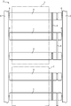
- FIG. 1 It is sectional drawing for demonstrating the structure of the roller with a built-in motor which concerns on one Embodiment of this invention. It is a top view of the roller conveyor apparatus using the roller with a built-in motor of FIG. It is a figure which shows the structure of a bearing cover, (a) is an axial sectional drawing, (b) And (c) is a side view orthogonal to an axial line. It is a figure which shows the structure of a side plate, (a) is an axial sectional view, (b) is a side view orthogonal to an axis. It is a disassembled perspective view near a power transmission mechanism.
- FIG. 1 is a cross-sectional view for explaining the structure of a motor built-in roller 1 according to an embodiment of the present invention
- FIG. 2 is a plan view of a roller conveyor device 2 using the motor built-in roller 1.
- this motor built-in roller 1 is a driving roller that is used every predetermined number (three in FIG. 2) in the conveying direction in the roller conveyor device 2, and the remaining rollers 3 to be driven rollers Are connected by a belt 4 wound around one end thereof.
- These rollers 1 and 3 are pivotally supported by a pair of support shafts 6 (6a and 6b) which are provided upright from a pair of conveyor frames 5 so as to face each other.
- the rotational torque of the motor built-in roller 1 is transmitted to the remaining rollers 3 so that the work 7 mounted on these rollers 1 and 3 can be conveyed.
- the roller 1 with a built-in motor can be rotated with respect to the conveyor frame 5 by having both ends pivotally supported on the pair of support shafts 6 by bearings 11 and 12.
- a roller tube 13, an inner frame 14 fixed to one support shaft 6 a in the roller tube 13, a motor 15 and a speed reduction mechanism 16 mounted on the inner frame 14, and the roller tube 13 are provided.
- a power transmission mechanism 17 that transmits the torque of the motor 15 to the roller tube 13.
- FIG. 3 is a view showing the structure of the bearing cover 21,
- FIG. 3 (a) is an axial sectional view similar to FIG. 1, and FIGS. 3 (b) and 3 (c) are orthogonal to the axis. It is a side view of a direction.
- the bearing cover 21 is made of a material such as resin, and has a cylindrical portion 21b having a hexagonal columnar hole 21a corresponding to the support shafts 6a and 6b formed in a hexagonal columnar shape, and an outer portion of the roller tube 13 in the cylindrical portion 21b. And a flange portion 21c extending outward in the radial direction from the end portion on the side. The flange portion 21 c prevents dust from entering the bearings 11 and 12.
- the cylindrical portion 21b has slits 21d formed at equal intervals in the circumferential direction from the end portion on the inner side of the roller tube 13, and the outer peripheral surface of the end portion on the inner side of the roller tube 13. Is formed with a locking claw 21e. For this reason, when the cylindrical portion 21b is fitted in the inner peripheral portion of the bearing 11, the cylindrical portion 21b separated by the slit 21d is bent inward, and when the cylindrical portion 21b is completely fitted, the locking claw 21e is engaged with the bearing 11. The cylindrical portion 21b is restored and the support shafts 6a and 6b can be inserted.
- FIG. 4 is a view showing the structure of the side plate 22, FIG. 4 (a) is an axial sectional view similar to FIG. 1, and FIG. 4 (b) is a side view perpendicular to the axis. It is.
- the side plate 22 is also made of a material such as resin, and extends from the cylindrical portion 22a into which the bearing 11 is fitted and the end portion which is the inner side of the roller tube 13 in the cylindrical portion 22a to the radially inner side.
- a latching claw 22c extending radially outward from an end portion on the outer side of the roller tube 13 in the cylindrical portion 22a.
- the locking claw 22c is formed in a flange shape.
- a gentle V-groove 22d is carved at the base end of the locking claw 22c, and the inner end is chamfered and guided.
- a slope 22e is formed.
- a step 22f into which the outer peripheral edge of the flange portion 21c of the bearing cover 21 is fitted is formed on the inner side in the radial direction from the end portion on the outer side of the roller tube 13 in the cylindrical portion 22a. Therefore, when the roller tube 13 is fitted, it is easily fitted by the guide slope 22e, and the end of the roller tube 13 is in contact with the locking claw 22c, and the V groove 22d The above-described caulking is stopped.
- the bearing 11 provided on the inner peripheral side of the cylindrical portion 22a is also prevented from coming off with the locking claw 22b.
- the side plate on the side of the support shaft 6 b where the load increases is provided with another bearing 12 shown below, whereas the support shaft 6 a with a small load is provided. Only the bearing 11 is provided on the side plate on the side, and a cylindrical spacer 23 is interposed in a gap corresponding to the bearing 12 in the cylindrical portion 22a.
- the support shaft 6b is a hexagonal columnar slide shaft that is slidable in the axial direction in the hole 21a of the cylindrical portion 21b, and a spring 24 that pushes back the support shaft 6b is provided on the inner end thereof.
- the spring 24 is covered with a spring cover 25, and the spring 24 is supported by the bearing 12 from the spring cover 25. Therefore, in the roller 1 with a built-in motor assembled as described later, with the support shaft 6b pushed in, the opposite support shaft 6a is inserted into the hexagonal hole of the conveyor frame 5, and the support shaft 6b Furthermore, the motor-equipped roller 1 is attached to the conveyor frame 5 by facing the hexagonal hole of the corresponding conveyor frame 5 and projecting into the hole.
- the support shaft 6a is formed hollow, and an electric wire 27 is drawn into the support shaft 6 via a protective tube 26.
- the electric wire 27 includes one or a plurality of power supply lines that supply power to the motor 15 and, if necessary, signal lines.
- the power supply lines are two, + and ⁇ , and when the conveyor frame 5 is used as the GND line from the support shaft 6a and the roller tube 13, it is one +.
- phase alternating current it consists of three.
- the signal line a control signal line, a sensor signal line, or the like is used.
- the inner frame 14 is fixed to the support shaft 6a by screws 28. As described above, the motor 15 and the speed reduction mechanism 16 are mounted on the internal frame 14.
- the speed reduction mechanism 16 includes a two-stage planetary gear, and the output thereof is output from a bearing 29 fixed to the internal frame 14 and input to the power transmission mechanism 17.
- the power transmission mechanism 17 includes a first member 33 that receives torque from the motor 15, a second member 34 that is fitted into the first member 33, and the axis of the roller tube 13.
- the bolt 35 is configured to fasten and press the second member 34 against the first member 33, and the double-sided tape 37 laid on the outer peripheral surface of the first member 33.
- a spline hub 31 is fitted into the first member 33 on a spline shaft 30 that is an output shaft of the bearing 29, and the torque is transmitted from an interposition member 32 placed on the spline hub 31.
- the double-sided tape 37 is attached to the outer peripheral surface of the rubber damper 36 after the rubber damper 36 is put on the outer peripheral surface of the first member 33.
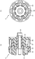
- FIG. 5 is an exploded perspective view of the vicinity of the power transmission mechanism 17, and FIG. 6 is an enlarged cross-sectional view of the power transmission mechanism 17.
- FIG. 7 is a view showing the structure of the spline hub 31. 6 (a) and 7 (a) are axial sectional views similar to FIG. 1, and FIGS. 6 (b), 7 (b) and 7 (c) are side views perpendicular to the axis. It is.
- FIG. 7 and the drawings to be described later in addition to FIG. 1, in order to clarify more parts, there is a figure in which the section line is not a straight line, and the cross-sectional part of FIG. This is indicated by the section line.
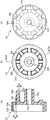
- the spline hub 31 has a groove 31a into which the spline shaft 30 is fitted on the inner periphery, and a cylindrical body having grooves 31b and therefore protrusions 31d at equal intervals in the outer periphery (eight in FIG. 6).
- a sintered alloy SMF5040 for example, a sintered alloy SMF5040.
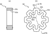
- FIG. 8 is a view showing the structure of the interposition member 32 into which the spline hub 31 is fitted.
- FIG. 8A is an axial sectional view similar to FIG. 1, and FIG. 8B is orthogonal to the axis. It is a side view of a direction.
- the interposed member 32 is made of, for example, a rubber molded NBR (nitrile rubber), and is covered with the spline hub 31 for buffering. .
- the inner circumferential groove 32a and the projection 32d correspond to the projection 31d and the groove 31b of the spline hub 31, and the outer circumferential groove 32b and the projection 32e are in phase with the inner circumferential projection 32d and the groove 32a.
- the spline hub 31 and the interposition member 32 it is possible to flexibly center the shaft of the roller tube 13 caused by a load and absorb the impact. Gear breakage can be prevented and noise can be reduced.
- the third cylindrical portion 33f is disposed concentrically and is made of a resin molded product.
- the second cylindrical portion 33e has tapered surfaces 33g and 33h having an inclination angle ⁇ , for example, 5 ° on the inner peripheral side and the outer peripheral side (the axial cross section is wedge-shaped), and positions at equal intervals in the circumferential direction.
- a slit 33i extending in the axial direction is formed.
- FIG. 10 is a view showing the structure of the second member 34
- FIG. 10 (a) is an axial sectional view similar to FIG. 1, and FIG. 10 (b) and FIG. 10 (c) It is a side view in the direction orthogonal to the axis.
- the second member 34 includes an end plate 34b in a cylindrical portion 34a fitted between the second cylindrical portion 33e and the third cylindrical portion 33f of the first member 33, and the cylindrical portion 34a.
- the outer peripheral surface is provided with protrusions 34c fitted into every other slit 33i, and is made of a resin molded product.
- the end plate 34b has a hole 34d through which the bolt 35 is inserted.
- the outer peripheral surface of the cylindrical portion 34a has a tapered surface 34e having an inclination angle ⁇ , for example, 5 °.
- FIG. 11 is a view showing the structure of the rubber damper 36
- FIG. 11 (a) is an axial sectional view similar to FIG. 1
- FIG. 11 (b) is a side view perpendicular to the axis.
- the rubber damper 36 includes protrusions 36b that are fitted into every other slit 33i on the inner circumferential surface of a cylindrical portion 36a that is fitted into the outer circumferential surface of the third cylindrical portion 33f of the first member 33.
- NBR nonitrile rubber
- a double-sided tape 37 is affixed to the outer peripheral surface of the rubber damper 36, and the adhesive layer of the double-sided tape 37 is composed of a pressure-sensitive adhesive layer. Therefore, the power consisting of the spline hub 31, the interposition member 32, the first member 33, the second member 34, the rubber damper 36 and the double-sided tape 37 is mounted on the inner frame 14 on which the motor 15, the speed reduction mechanism 16 and the bearing are mounted. After the transmission mechanism 17 is temporarily fixed by the bolt 35, the cylindrical roller tube 13 is covered, and after the bolt 35 is finally tightened, both ends of the roller tube 13 are directed toward the V groove 22 d of the side plate 22. Anti-caulking is performed. Thus, the motor built-in roller 1 is completed.
- the length of the roller tube 13 is appropriately selected according to the width of the roller conveyor device 2.
- another bearing 29 is provided on the inner frame 34 fixed to the conveyor frame 5. Therefore, as described above, there are two bearings 29 on the support shaft 6b side. Bearings 11 and 12 are provided.
- the power transmission mechanism 17 includes the speed reduction mechanism 16 between the motor 15 and the first member 33. Therefore, by using a planetary gear or the like for the reduction mechanism 16, a large reduction ratio can be obtained and a large torque can be transmitted.
- the double-sided tape 37 is laid. It is to be done.
- the rubber damper layer 36 By interposing the rubber damper layer 36, it is possible to compensate for the axial deviation between the roller tube 13 and the motor 15 and the power transmission mechanism 17 and the lack of roundness of the roller tube 13, as well as shock absorption and Vibration can be reduced.
- the rubber damper layer 36 even if a plurality of slits 33 i are formed in the third cylindrical portion 33 f (peripheral wall) of the first member 33 whose diameter is increased, the rubber damper layer 36 is a roller. Since the inner peripheral surface of the pipe 13 is pressed uniformly, the formation of the slit 33i can make the first member 33 made of a resin molded product easier to expand in diameter.
- first member 33 and the second member 34 to be fitted to each other may be on the outer side to press the rubber damper layer 36, and the tapered surfaces 33g and 34e are also formed on at least one of them. It only has to be.
- the roller built-in motor for roller conveyors includes a roller tube pivotally supported by a pair of support shafts standing upright from each other from a pair of conveyor frames, and one support shaft in the roller tube.
- a roller-conveyor motor-equipped roller provided in the roller tube and configured to include a power transmission mechanism that transmits torque of the motor to the roller tube.
- the first and second members which are formed in a bottomed cylindrical shape and the other is fitted into one, and the first member that receives torque from the output shaft of the motor, the second member in the axial direction.
- the peripheral walls of the first and second members at least one of the mutually facing surfaces is formed in a tapered shape (wedge in cross section), and the peripheral wall on which the pressure-sensitive adhesive layer is laid.
- the outer wall of the first or second member is formed so that its diameter can be increased, and the peripheral wall pressed by the taper surface by the pressing by the screwing member expands, and the pressure-sensitive adhesive layer exhibits an adhesive force.
- the surface and the inner peripheral surface of the roller tube are bonded together.
- the roller built-in motor for a roller conveyor includes a rubber damper layer on the outer peripheral surface of the first or second member on which the pressure-sensitive adhesive layer is laid in the power transmission mechanism. After being laminated, the pressure-sensitive adhesive layer is laid.
- the rubber damper layer by interposing the rubber damper layer, it is possible to compensate for an axial misalignment between the roller tube and the motor and the power transmission mechanism and a lack of roundness of the roller tube, and the expansion. Even if a plurality of slits are formed on the peripheral wall of the first or second member having a diameter, the rubber damper layer uniformly presses the inner peripheral surface of the roller tube. In the first and second members, the diameter can be more easily increased.
- the present invention uses a glue layer to bond a power transmission mechanism in a roller tube and the roller tube, thereby preventing slippage due to aging and the like. It is suitable as.
Landscapes
- Engineering & Computer Science (AREA)
- Mechanical Engineering (AREA)
- Rollers For Roller Conveyors For Transfer (AREA)
Abstract
Priority Applications (4)
| Application Number | Priority Date | Filing Date | Title |
|---|---|---|---|
| US12/992,914 US8381901B2 (en) | 2008-05-16 | 2008-05-16 | Roller conveyor motorized roller and roller conveyor device using the same |
| JP2010511828A JP5314678B2 (ja) | 2008-05-16 | 2008-05-16 | ローラコンベヤー用モータ内蔵ローラおよびそれを用いるローラコンベヤー装置 |
| CN200880129236.8A CN102026894B (zh) | 2008-05-16 | 2008-05-16 | 辊式输送机用电动机内置辊及使用其的辊式输送机装置 |
| PCT/JP2008/059060 WO2009139068A1 (fr) | 2008-05-16 | 2008-05-16 | Rouleau de transporteur à rouleaux à moteur intégré et dispositif transporteur à rouleaux utilisant ce dernier |
Applications Claiming Priority (1)
| Application Number | Priority Date | Filing Date | Title |
|---|---|---|---|
| PCT/JP2008/059060 WO2009139068A1 (fr) | 2008-05-16 | 2008-05-16 | Rouleau de transporteur à rouleaux à moteur intégré et dispositif transporteur à rouleaux utilisant ce dernier |
Publications (1)
| Publication Number | Publication Date |
|---|---|
| WO2009139068A1 true WO2009139068A1 (fr) | 2009-11-19 |
Family
ID=41318450
Family Applications (1)
| Application Number | Title | Priority Date | Filing Date |
|---|---|---|---|
| PCT/JP2008/059060 Ceased WO2009139068A1 (fr) | 2008-05-16 | 2008-05-16 | Rouleau de transporteur à rouleaux à moteur intégré et dispositif transporteur à rouleaux utilisant ce dernier |
Country Status (4)
| Country | Link |
|---|---|
| US (1) | US8381901B2 (fr) |
| JP (1) | JP5314678B2 (fr) |
| CN (1) | CN102026894B (fr) |
| WO (1) | WO2009139068A1 (fr) |
Cited By (9)
| Publication number | Priority date | Publication date | Assignee | Title |
|---|---|---|---|---|
| JP2014024645A (ja) * | 2012-07-27 | 2014-02-06 | Ito Denki Kk | 動力伝達部材、並びに、モータ内蔵ローラ |
| DE202013002290U1 (de) * | 2013-03-11 | 2014-06-12 | Interroll-Holding Ag | Förderrolle mit Versteifungselement |
| JP2015214379A (ja) * | 2014-05-07 | 2015-12-03 | 伊東電機株式会社 | モータ内蔵ローラ、動力伝達部材及びモータ内蔵ローラの製造方法 |
| JP2016204136A (ja) * | 2015-04-24 | 2016-12-08 | 伊東電機株式会社 | モータ内蔵ローラ、及び動力伝達部材 |
| WO2018002070A1 (fr) * | 2016-06-30 | 2018-01-04 | Interroll Holding Ag | Unité d'entraînement pour un tambour moteur, tambour moteur, flasque arrière et procédés de production |
| JP2020502007A (ja) * | 2016-12-16 | 2020-01-23 | インターロール・ホールディング・アーゲー | 摩擦嵌合および/または一体型カップリングブッシュを備える搬送ローラ |
| CN111674930A (zh) * | 2020-06-12 | 2020-09-18 | 徐州鑫路达配送服务有限公司 | 一种用于利用水利管道的新型地下物流系统的物流胶囊 |
| EP3715285A1 (fr) * | 2019-03-08 | 2020-09-30 | Intelligrated Headquarters LLC | Rouleau de convoyeur motorisé comportant un ensemble d'entraînement |
| WO2023119355A1 (fr) | 2021-12-20 | 2023-06-29 | 株式会社協和製作所 | Butoir, transporteur à rouleaux et transporteur à courroie |
Families Citing this family (43)
| Publication number | Priority date | Publication date | Assignee | Title |
|---|---|---|---|---|
| US9399556B2 (en) | 2011-08-11 | 2016-07-26 | Mol Belting Systems, Inc. | End lid design and removal tool |
| WO2013143550A1 (fr) | 2012-03-30 | 2013-10-03 | P. Ellegaard A/S | Moteur-tambour hygiénique |
| DE202012005380U1 (de) * | 2012-06-01 | 2013-09-03 | Interroll-Holding Ag | Motorbetriebene Förderrolle für Förderanlagen zum Fördern von Behältern, Paletten und dergleichen |
| DE202012008919U1 (de) | 2012-09-18 | 2014-01-22 | Interroll-Holding Ag | Förderrolle mit Kopfelement |
| JP6295451B2 (ja) * | 2012-10-10 | 2018-03-20 | 伊東電機株式会社 | 動力伝達部材、並びに、モータ内蔵ローラ |
| US9382070B2 (en) | 2012-10-24 | 2016-07-05 | Big Dutchman International Gmbh | Conveyor and method to convey animal products in an agricultural business |
| DE102013002754A1 (de) * | 2013-02-19 | 2014-08-21 | Heidelberger Druckmaschinen Ag | Vorrichtung zum Auslegen von in einem Produktstrom zugeführten Druckereiprodukten in zwei voneinander getrennten Stapeln |
| US9926140B2 (en) * | 2013-04-30 | 2018-03-27 | Itoh Denki Co., Ltd. | Roller conveyor device, controller, and mechanical device abnormality detection method |
| AT514981B1 (de) * | 2013-10-11 | 2016-01-15 | Tgw Mechanics Gmbh | Förderrolle und Förderanlage mit Feuchtigkeitsschutz |
| ITBG20130031A1 (it) * | 2013-10-11 | 2015-04-12 | Rulli Rulmeca S P A | Rullo di trasporto motorizzato |
| AT514980B1 (de) | 2013-10-11 | 2015-12-15 | Tgw Mechanics Gmbh | Schwenklager und Förderrolle für einen schrägen Einbau derselben in eine Förderanlage |
| AT514999B1 (de) | 2013-11-06 | 2015-11-15 | Tgw Mechanics Gmbh | Verfahren zum Adressieren/Reihen linear verketteter Steuerkomponenten einer Förderanlage |
| DE202014000757U1 (de) * | 2014-01-30 | 2015-05-04 | Interroll Holding Ag | Trommelmotor für lärmempfindliche Umgebung |
| DE202014007282U1 (de) | 2014-09-12 | 2015-12-16 | Big Dutchman International Gmbh | Dosiervorrichtung |
| DE102014222171A1 (de) * | 2014-10-30 | 2016-05-04 | Interroll Holding Ag | Fördereinrichtung für Förderanlagen, modulares System und Verfahren zum Herstellen einer solchen Fördereinrichtung |
| AT516925B1 (de) | 2015-03-12 | 2021-08-15 | Tgw Mechanics Gmbh | Fördereinrichtung mit verbesserter Verdrahtung von Antriebsmotor und Bremse einer Förderrolle sowie Betriebsverfahren dafür |
| DE102015106034A1 (de) | 2015-04-20 | 2016-10-20 | Interroll Holding Ag | Installationsverfahren zum Einrichten von Fördervorrichtungen |
| DE102015106026B3 (de) | 2015-04-20 | 2016-08-25 | Interroll Holding Ag | Verfahren zum Austausch einer Steuerungseinheit in einer Fördervorrichtung |
| DE102015107167A1 (de) | 2015-05-07 | 2016-11-10 | Interroll Holding Ag | Steuerungseinheit für eine Fördervorrichtung mit Hardware-Erkennung |
| KR101690943B1 (ko) * | 2015-09-08 | 2017-01-09 | 주식회사 보우시스템 | 컨베이어용 전동 롤러의 동력전달 조인트 |
| WO2017205288A1 (fr) * | 2016-05-23 | 2017-11-30 | Hilmot LLC | Système de rouleau comportant un moteur de rotor externe espacé |
| DE102016112051B4 (de) | 2016-06-30 | 2024-01-04 | Interroll Holding Ag | Modulsystem für motorbetriebene Förderrollen |
| DE102016112054B4 (de) | 2016-06-30 | 2021-08-12 | Interroll Holding Ag | Trommelmotor mit alternativer Getriebeaufnahme |
| DE102016114524B4 (de) | 2016-08-05 | 2020-09-03 | Interroll Holding Ag | Trommelmotor mit Frequenzumrichter und optionalem Bandspannungssensor |
| DE102016114672A1 (de) | 2016-08-08 | 2018-02-08 | Interroll Holding Ag | Elektrische Steckverbindung für Motorrollen |
| US9994398B1 (en) * | 2016-08-16 | 2018-06-12 | Tech-Roll Inc. | Powered roller systems and methods |
| DE202016105370U1 (de) | 2016-09-27 | 2018-01-02 | Big Dutchman International Gmbh | Fütterungsvorrichtung für Geflügeltiere |
| EP3373232B1 (fr) | 2017-03-09 | 2020-12-09 | Interroll Holding AG | Agencement intralogistique |
| DE102017118817B4 (de) | 2017-08-17 | 2019-05-23 | Interroll Holding Ag | Hybriddeckel |
| CN108545398A (zh) * | 2018-05-31 | 2018-09-18 | 深圳市艾励美特科技有限公司 | 一种滚筒和滚筒传送装置 |
| US11034524B2 (en) * | 2019-03-12 | 2021-06-15 | Fetch Robotics, Inc. | Robotic payload transport system |
| WO2021030479A1 (fr) | 2019-08-13 | 2021-02-18 | Kamran Ramezani | Transporteur à configuration de moteur étendue |
| CN112173584B (zh) | 2020-09-03 | 2024-06-11 | 上海宝羽自动化系统设备有限公司 | 一种单件分离系统 |
| US11795005B2 (en) | 2020-11-19 | 2023-10-24 | Laitram, L.L.C. | Hygienic conveyor roller |
| EP4080302B1 (fr) * | 2021-04-20 | 2023-09-06 | Kyowa Europe GmbH | Système de convoyeur, contrôleur à rouleaux motorisé et procédé de fonctionnement d'un système de convoyeur |
| US11603269B2 (en) * | 2021-08-05 | 2023-03-14 | Dorner Mfg. Corp. | Mounting assembly for gearmotor of a conveyor assembly |
| CN114229344B (zh) * | 2022-01-06 | 2024-02-02 | 青岛大牧人机械股份有限公司 | 一种抓鸡输送机用双层辊 |
| CN218440534U (zh) * | 2022-08-03 | 2023-02-03 | 厦门华尔达智能科技股份有限公司 | 管状电机的降噪减震结构 |
| JP7795204B2 (ja) * | 2022-10-25 | 2026-01-07 | 株式会社協和製作所 | コンベア用モータ内蔵ローラおよびコンベア装置 |
| CN116054478A (zh) * | 2023-02-15 | 2023-05-02 | 深圳市兆威机电股份有限公司 | 张紧结构及滚筒电机 |
| WO2025065537A1 (fr) * | 2023-09-28 | 2025-04-03 | 德昌电机(江门)有限公司 | Rouleau à entraînement direct et dispositif transporteur du type rouleau |
| CN117361055A (zh) * | 2023-11-28 | 2024-01-09 | 东莞怡合达自动化股份有限公司 | 电动滚筒及输送机 |
| CN223015543U (zh) * | 2024-08-16 | 2025-06-24 | 兰剑智能科技股份有限公司 | 一种挤压式电辊筒及输送系统 |
Citations (5)
| Publication number | Priority date | Publication date | Assignee | Title |
|---|---|---|---|---|
| JPH05212363A (ja) * | 1992-02-04 | 1993-08-24 | Fujitsu Ltd | シリコンゴムローラ及びその表面洗浄方法 |
| JPH05306009A (ja) * | 1992-04-28 | 1993-11-19 | Shiyoudenshiya:Kk | 外筒固定装置付き駆動ホイール |
| JPH10122252A (ja) * | 1996-10-16 | 1998-05-12 | Kyowa Seisakusho:Kk | 軸継手 |
| JPH1179358A (ja) * | 1997-09-11 | 1999-03-23 | Ito Denki Kk | モータ内蔵ローラ |
| JP2001194954A (ja) * | 2000-01-11 | 2001-07-19 | Fuji Xerox Co Ltd | 電子写真感光体に内在させる充填部材の固定方法、並びに、電子写真感光体および電子写真用プロセスカートリッジ |
Family Cites Families (7)
| Publication number | Priority date | Publication date | Assignee | Title |
|---|---|---|---|---|
| US4028086A (en) * | 1976-02-25 | 1977-06-07 | Libbey-Owens-Ford Company | Apparatus for bending and tempering glass sheets by differential cooling |
| US4167997A (en) * | 1978-03-15 | 1979-09-18 | Libbey-Owens-Ford Company | Conveyor roll construction |
| US5088596A (en) | 1990-12-17 | 1992-02-18 | Interroll Holding A. G. | Motorized conveyor roller |
| CN2565780Y (zh) | 2002-08-02 | 2003-08-13 | 李文亮 | 摆线针轮减速机电动滚筒 |
| CN2619911Y (zh) | 2003-05-21 | 2004-06-09 | 徐其国 | 摆线针轮电动滚筒 |
| DE10336304B4 (de) * | 2003-07-31 | 2020-08-27 | Interroll Holding Ag | Motorbetriebene Förderrolle, Steuervorrichtung für eine motorbetriebene Förderrolle, Rollenförderanlage und Steuerverfahren für eine Rollenförderanlage |
| JP4243720B2 (ja) | 2004-04-20 | 2009-03-25 | 株式会社ササクラ | 消音ルーバー |
-
2008
- 2008-05-16 US US12/992,914 patent/US8381901B2/en active Active
- 2008-05-16 JP JP2010511828A patent/JP5314678B2/ja active Active
- 2008-05-16 WO PCT/JP2008/059060 patent/WO2009139068A1/fr not_active Ceased
- 2008-05-16 CN CN200880129236.8A patent/CN102026894B/zh active Active
Patent Citations (5)
| Publication number | Priority date | Publication date | Assignee | Title |
|---|---|---|---|---|
| JPH05212363A (ja) * | 1992-02-04 | 1993-08-24 | Fujitsu Ltd | シリコンゴムローラ及びその表面洗浄方法 |
| JPH05306009A (ja) * | 1992-04-28 | 1993-11-19 | Shiyoudenshiya:Kk | 外筒固定装置付き駆動ホイール |
| JPH10122252A (ja) * | 1996-10-16 | 1998-05-12 | Kyowa Seisakusho:Kk | 軸継手 |
| JPH1179358A (ja) * | 1997-09-11 | 1999-03-23 | Ito Denki Kk | モータ内蔵ローラ |
| JP2001194954A (ja) * | 2000-01-11 | 2001-07-19 | Fuji Xerox Co Ltd | 電子写真感光体に内在させる充填部材の固定方法、並びに、電子写真感光体および電子写真用プロセスカートリッジ |
Cited By (14)
| Publication number | Priority date | Publication date | Assignee | Title |
|---|---|---|---|---|
| JP2014024645A (ja) * | 2012-07-27 | 2014-02-06 | Ito Denki Kk | 動力伝達部材、並びに、モータ内蔵ローラ |
| DE202013002290U1 (de) * | 2013-03-11 | 2014-06-12 | Interroll-Holding Ag | Förderrolle mit Versteifungselement |
| US9493305B2 (en) | 2013-03-11 | 2016-11-15 | Interroll Holding Ag | Conveyor roller with reinforcement element |
| JP2015214379A (ja) * | 2014-05-07 | 2015-12-03 | 伊東電機株式会社 | モータ内蔵ローラ、動力伝達部材及びモータ内蔵ローラの製造方法 |
| JP2016204136A (ja) * | 2015-04-24 | 2016-12-08 | 伊東電機株式会社 | モータ内蔵ローラ、及び動力伝達部材 |
| US11309767B2 (en) | 2016-06-30 | 2022-04-19 | Interroll Holding Ag | Drive unit for a drum motor, drum motor, rear flange and production method |
| WO2018002070A1 (fr) * | 2016-06-30 | 2018-01-04 | Interroll Holding Ag | Unité d'entraînement pour un tambour moteur, tambour moteur, flasque arrière et procédés de production |
| JP2020502007A (ja) * | 2016-12-16 | 2020-01-23 | インターロール・ホールディング・アーゲー | 摩擦嵌合および/または一体型カップリングブッシュを備える搬送ローラ |
| US10926959B2 (en) | 2016-12-16 | 2021-02-23 | Interroll Holding Ag | Conveying roller with frictionally fitting and/or integral coupling bushing |
| EP3715285A1 (fr) * | 2019-03-08 | 2020-09-30 | Intelligrated Headquarters LLC | Rouleau de convoyeur motorisé comportant un ensemble d'entraînement |
| US11136194B2 (en) | 2019-03-08 | 2021-10-05 | Intelligrated Headquarters, Llc | Motorized conveyor roller with drive assembly |
| CN111674930A (zh) * | 2020-06-12 | 2020-09-18 | 徐州鑫路达配送服务有限公司 | 一种用于利用水利管道的新型地下物流系统的物流胶囊 |
| WO2023119355A1 (fr) | 2021-12-20 | 2023-06-29 | 株式会社協和製作所 | Butoir, transporteur à rouleaux et transporteur à courroie |
| US12479669B2 (en) | 2021-12-20 | 2025-11-25 | Kyowa Manufacturing Co., Ltd. | Stopper, roller conveyor, and belt conveyor |
Also Published As
| Publication number | Publication date |
|---|---|
| CN102026894A (zh) | 2011-04-20 |
| JP5314678B2 (ja) | 2013-10-16 |
| US20110062000A1 (en) | 2011-03-17 |
| CN102026894B (zh) | 2014-04-02 |
| JPWO2009139068A1 (ja) | 2011-09-15 |
| US8381901B2 (en) | 2013-02-26 |
Similar Documents
| Publication | Publication Date | Title |
|---|---|---|
| JP5314678B2 (ja) | ローラコンベヤー用モータ内蔵ローラおよびそれを用いるローラコンベヤー装置 | |
| JP5351377B2 (ja) | 力制限アセンブリ | |
| US8764574B2 (en) | Coupling | |
| US6413164B1 (en) | Torsionally rigid, play-free, flexible metal bellows-type coupling for the torque-transmissive connection of two shafts | |
| WO2012017917A1 (fr) | Dispositif amortisseur | |
| US6955252B2 (en) | Device for isolating torque fluctuations | |
| US20130180818A1 (en) | Coupling apparatus with two couplings | |
| JP2003074580A (ja) | 動力伝達装置 | |
| CN1241810C (zh) | 用于从底带传送膜的手持装置的滑动离合器 | |
| CN102725555B (zh) | 离心式离合器设备 | |
| JP2001065588A (ja) | 回転弾性クラッチ | |
| CN110662909A (zh) | 扭振减振器 | |
| US20110319176A1 (en) | Device for the vibration-reducing transmission of torques | |
| JP2005330991A (ja) | 圧縮機の動力伝達装置 | |
| JP2001346387A (ja) | 振動波駆動装置 | |
| CN116648368A (zh) | 具有扭矩限制特征以保护其部件的解耦器 | |
| KR20120129184A (ko) | 기어드 모터의 부하 테스트 장치 | |
| US7731005B2 (en) | Lock-up clutch mechanism for torque converter | |
| JP2004116574A (ja) | クラッチディスク及びクラッチディスク組立体 | |
| JP2002276777A (ja) | 動力伝達装置 | |
| EP2963311A2 (fr) | Dispositif d'amortisseur | |
| JP2003090359A (ja) | 一方向クラッチ | |
| JPH1026182A (ja) | コイルスプリング組立体及びダンパー機構 | |
| CN110617298A (zh) | 用于扭振减振器的毂 | |
| CN119554373A (zh) | 限扭减振器 |
Legal Events
| Date | Code | Title | Description |
|---|---|---|---|
| WWE | Wipo information: entry into national phase |
Ref document number: 200880129236.8 Country of ref document: CN |
|
| 121 | Ep: the epo has been informed by wipo that ep was designated in this application |
Ref document number: 08752893 Country of ref document: EP Kind code of ref document: A1 |
|
| WWE | Wipo information: entry into national phase |
Ref document number: 2010511828 Country of ref document: JP |
|
| WWE | Wipo information: entry into national phase |
Ref document number: 12992914 Country of ref document: US |
|
| NENP | Non-entry into the national phase |
Ref country code: DE |
|
| 122 | Ep: pct application non-entry in european phase |
Ref document number: 08752893 Country of ref document: EP Kind code of ref document: A1 |