WO2009142111A1 - Procédé et dispositif de détection de fil câblé dépassant d’une partie talon - Google Patents
Procédé et dispositif de détection de fil câblé dépassant d’une partie talon Download PDFInfo
- Publication number
- WO2009142111A1 WO2009142111A1 PCT/JP2009/058613 JP2009058613W WO2009142111A1 WO 2009142111 A1 WO2009142111 A1 WO 2009142111A1 JP 2009058613 W JP2009058613 W JP 2009058613W WO 2009142111 A1 WO2009142111 A1 WO 2009142111A1
- Authority
- WO
- WIPO (PCT)
- Prior art keywords
- tire
- protruding
- bead portion
- displacement
- cord
- Prior art date
- Legal status (The legal status is an assumption and is not a legal conclusion. Google has not performed a legal analysis and makes no representation as to the accuracy of the status listed.)
- Ceased
Links
Images


Classifications
-
- B—PERFORMING OPERATIONS; TRANSPORTING
- B29—WORKING OF PLASTICS; WORKING OF SUBSTANCES IN A PLASTIC STATE IN GENERAL
- B29D—PRODUCING PARTICULAR ARTICLES FROM PLASTICS OR FROM SUBSTANCES IN A PLASTIC STATE
- B29D30/00—Producing pneumatic or solid tyres or parts thereof
- B29D30/06—Pneumatic tyres or parts thereof (e.g. produced by casting, moulding, compression moulding, injection moulding, centrifugal casting)
- B29D30/0601—Vulcanising tyres; Vulcanising presses for tyres
- B29D30/0633—After-treatment specially adapted for vulcanising tyres
-
- G—PHYSICS
- G01—MEASURING; TESTING
- G01M—TESTING STATIC OR DYNAMIC BALANCE OF MACHINES OR STRUCTURES; TESTING OF STRUCTURES OR APPARATUS, NOT OTHERWISE PROVIDED FOR
- G01M17/00—Testing of vehicles
- G01M17/007—Wheeled or endless-tracked vehicles
- G01M17/02—Tyres
-
- B—PERFORMING OPERATIONS; TRANSPORTING
- B29—WORKING OF PLASTICS; WORKING OF SUBSTANCES IN A PLASTIC STATE IN GENERAL
- B29D—PRODUCING PARTICULAR ARTICLES FROM PLASTICS OR FROM SUBSTANCES IN A PLASTIC STATE
- B29D30/00—Producing pneumatic or solid tyres or parts thereof
- B29D30/0061—Accessories, details or auxiliary operations not otherwise provided for
- B29D2030/0066—Tyre quality control during manufacturing
Definitions
- the present invention relates to a method and an apparatus for detecting a cord protruding from a tire bead portion.
- the cord of the internal component member sometimes protrudes from the surface to the bead portion of the tire, and conventionally, there are many parts that depend on human hands to inspect the protruding cord. That is, the operator touches the bead portion with his hand to detect the protruding code by touch, or detects the protruding code visually.
- the present invention has been made in view of the above points, and the object of the present invention is to reduce the labor and to detect the protruding code of the tire bead part quickly and reliably. And in providing a device.
- the bead portion in the state adjacent to the bead portion of the tire is provided with the hooking means that is hooked to the protruding cord that may protrude from the bead portion of the tire.
- the displacement of the hooking means in the rotational movement direction due to the hooking cord being caught by the hooking means is detected, and the protruding cord is detected by the displacement of the hooking means.
- a protruding code detection method for a tire bead portion is provided.
- the catching means is disposed adjacent to the bead portion of the tire and the tire is rotated.
- a displacement member having a surface fastener curved along the surface shape of the bead portion of the tire is used as the catching means.
- a hooking means for hooking on a protruding cord that may protrude from a bead portion of a tire, and rotating the tire around a tire central axis
- Rotating means supporting means for supporting the catching means adjacent to the bead portion of the tire and allowing some displacement in the rotational direction
- displacement detecting means for detecting displacement of the catching means in the rotational direction
- a protruding code detection device for a tire bead portion.
- the displacement detecting means includes a limit switch that is operated by a displacement of the hooking means in a rotation direction.
- the hooking means has a surface fastener having a shape along the surface shape of the bead portion of the tire.
- the support means includes a spring that supports the hooking means.
- the support means includes a support member that can move relative to a tire, and the displacement detection means includes a swing member that is swingably supported by the support member, and the hook from the swing member. A pair of rods projecting so as to be able to be engaged with the holding means, and means for detecting the swinging of the swinging member.
- the hooking means for hooking the protruding cord that may protrude from the tire bead portion is rotated relative to the tire in a state adjacent to the tire bead portion. Since the displacement of the hooking means in the rotational direction is detected by the movement, if the protruding cord protrudes from the tire bead portion, the hooking means that rotates relatively adjacent to the tire bead portion The protruding cord comes into contact and gets caught, and the hooking means is pulled and displaced. By detecting the displacement of the hooking means, the labor can be reduced and the protruding cord can be detected easily and quickly. it can.
- the apparatus By arranging the hooking means adjacent to the bead portion of the tire and rotating the tire, the apparatus can be simplified and the equipment cost can be reduced rather than rotating the hooking means.
- the hooking means is provided with a surface fastener that is curved along the surface shape of the bead portion of the tire, so that the hook with the protruding cord does not pull the surface fastener firmly, but to the extent that the surface fastener is displaced to some extent.
- a plurality of protruding cords can be detected.
- all of one bead part can be test
- the catching means is adjacent to and supported by the bead portion of the tire that is rotated about the tire central axis by the rotating means and is allowed to be slightly displaced in the rotational direction. Therefore, if the protruding cord protrudes from the tire bead portion, the protruding cord comes into contact with and catches the hooking means that rotates relative to the bead portion of the tire, and pulls the hooking means.
- the displacement detecting means detects the displacement of the hooking means, the labor can be reduced and the protruding cord can be detected easily and quickly.
- the apparatus can be simplified and the equipment cost can be reduced.
- the hooking means is provided with a surface fastener having a shape along the surface shape of the bead portion of the tire, so that the hook with the protruding cord does not pull the surface fastener firmly, but to the extent that the surface fastener is displaced to some extent.
- a plurality of protruding cords can be detected.
- one bead part can be test
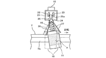
- FIG. 1 is a schematic plan view of a protruding code detection device according to an embodiment of the present invention. It is the side view made into the partial cross section of the code
- FIG. 3 is a partially enlarged side view of FIG. It is the side view which abbreviate
- T ... tyre, Tb ... bead part, p ... protruding cord, n ... cereal number, DESCRIPTION OF SYMBOLS 1 ... Projection code detection apparatus, 2 ... Turntable, 3 ... Rotating shaft, 5 ... Motor, 6 ... Gear, 8 ... Positioning slider, 10: Displacement member with surface fastener, 11 ... Surface fastener, 15 ... Support member, 16 ... Coil spring, 20 ... Displacement detector, 21 ... Switch box, 22, 23 ... Limit switch, 24 ... Support shaft, 25 ... Swing member, 26, 27 ... Metal rod, 50 ... PLC, 51 ... Rotary encoder, 52 ... Monitor.
- FIGS. Schematic diagrams of the protruding code detection device 1 according to the present embodiment are shown in FIGS.
- the code detection device 1 the tire T to be inspected is placed at a predetermined position on the rectangular turntable 2.
- the turntable 2 is horizontally fixed and supported at the upper end of the vertically oriented rotating shaft 3, and the rotational power of the drive shaft of the motor 5 is transmitted to the rotating shaft 3 through the meshing of the gears 6 and 7 to rotate.
- the shaft 3 rotates with the turntable 2.
- the turntable 2 constitutes a rotating means.
- four positioning sliders 8 that slide in the radial direction from the central axis C of the rotary shaft 2 are provided at equal intervals in the circumferential direction, and the four positioning sliders 8 always have the central axis C. Are configured to be linked to each other so as to slide while maintaining the same distance from each other. Therefore, by positioning the four positioning sliders 8 so as to grip the tire T from the outside, the center of the tire T can be easily aligned with the central axis C (centering).
- the support member 15 for suspending the displacement member 10 with the hook-and-loop fastener via the coil spring 16 is provided above the tire T placed centered on the upper surface of the turntable 2.
- a moving mechanism (not shown) that holds the support member 15 and moves in a predetermined radial direction or moves up and down is provided.
- the displacement member 10 with the surface fastener is supported so as to be adjacent to the inner side in the radial direction of the bead portion Tb on the inner peripheral edge of the tire T and to face the bead portion Tb.
- the displacement member 10 with the hook-and-loop fastener constitutes a hooking means.
- the support member 15 and the coil spring 16 constitute a support means.
- the displacement member 10 with a hook-and-loop fastener is attached to the lower end of the coil spring 16 projecting downward from the support member 15.
- the coil spring 16 has a large spring constant and mainly uses bending elasticity rather than vertically expanding and contracting, and the displacement member 10 with the hook-and-loop fastener can be displaced in the lateral direction when the coil spring 16 is bent.
- the displacement member 10 with the hook-and-loop fastener suspended by the coil spring 16 has a concave portion 10a curved along the surface shape of the bead portion Tb on the inner peripheral edge of the tire T.
- a hook-and-loop fastener 11 having a large number of loops planted on the inner surface is attached.
- the displacement member 10 with the surface fastener is suspended while the recess 10 a of the displacement member 10 with the surface fastener is loosely fitted to the bead portion Tb on the upper side of the tire T. More precisely, as shown in FIG. 3, in the displacement member 10 with the surface fastener, the surface fastener 11 provided on the inner surface of the recess 10a covering the surface of the bead portion b of the tire T is adjacent to the surface of the bead portion Tb. It is hung in the position to do.
- the cord of the tire constituent member may protrude from the surface, and the protruding cord p protrudes from the surface. Contact the loop of the fastener 11 (see FIG. 4).
- the motor 3 is driven to rotate the turntable 1 forward or backward.
- the displacement member 10 with the surface fastener relatively moves along the bead portion Tb of the tire T.
- the protruding cord p protruding from the bead portion b of the tire T protrudes in the direction opposite to the rotation direction of the tire T, the protruding cord p comes into contact with the loop of the hook-and-loop fastener 11 but slips on the loop and is caught. Absent.
- the protruding cord p protrudes substantially in the rotational direction of the tire T
- the turning protruding cord p bites into the loop of the hook and loop fastener 11 and is pulled together with the hook and loop fastener 11 to pull the displacement member 10 with the hook and loop fastener.
- the coil spring 16 bends elastically.
- the protruding cord p protruding from the bead portion b of the tire T is caught by the surface fastener 11 by either the forward rotation or the reverse rotation of the tire T, and the displacement member 10 with the surface fastener is displaced.
- a displacement detection device 20 for detecting the displacement of the displacement member 10 with the surface fastener is attached to the support member 15.
- a switch box 21 is fixed to the support member 15, and limit switches 22 and 23 of the displacement detector 20 are built in the switch box 21 (see FIGS. 4 and 5).
- left and right limit switches 22 and 23 are arranged symmetrically in the switch box 20, and the swing member 25 is pivotally supported on the support shaft 24 between the left and right limit switches 22 and 23. Is swingably provided.
- the swing member 25 has an upper extending portion 25a extending upward from the support shaft 24.
- the upper extending portion 25a is provided on the left and right side surfaces of the operating pieces 22s and 23s of the left and right limit switches 22 and 23, respectively. It touches.
- the swing member 25 is bifurcated downward from the support shaft 24 to form a pair of lower branch portions 25b and 25c.
- the lower branch portions 25b and 25c projecting downward from the switch box 20 are formed.
- the thin metal rods 26 and 27 having elasticity extend obliquely downward away from each other.
- the two metal rods 26 and 27 extending obliquely downward away from each other extend so that their lower portions sandwich the displacement member 10 with surface fasteners from both the left and right sides. Therefore, when the displacement member 10 with the surface fastener is displaced left or right, one of the metal rods 26, 27 is pushed by the displacement member 10 with the surface fastener, and the swing member 25 swings.
- the upper extending portion 24a operates the operating pieces 22s and 23s of the left and right limit switches 22 and 23 to turn on the switches (see FIG. 5).
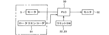
- the cord detection device 1 for detecting the protruding cord p of the bead portion b of the tire T is sequence-controlled by a PLC (Programmable Logic Controller) 50, and the PLC 50 controls the motor 5 as shown in FIG. Is provided with a rotary encoder 51.
- a signal detected by the rotary encoder 51 is input to the PLC 50, and the rotational speed of the tire T mounted on the turntable 2 is calculated from the motor rotational speed and the motor rotational speed.
- the PLC 50 monitors the state of the limit switches 22 and 23, and the ON signal of the limit switches 22 and 23 is input. The detection result of the protruding cord p is displayed on the monitor 52.
- the tire T is centered and placed on the turntable 2.
- the portion of the tire T to which the serial number n is attached is made to coincide with the direction in which the displacement member 10 with the surface fastener is set as viewed from the central axis C (see FIG. 1).
- the tire T is placed on the turntable 2 with the bead portion Tb on the side to which the serial number n is attached (the serial side) facing up.
- the radial position for suspending the displacement member 10 with the surface fastener is obtained by calculation from the outer dimensions of the tire T, and the vertical position is also matched with the upper bead portion Tb of the tire T placed on the turntable 2.
- the displacement member 10 with the surface fastener is set at a position where the surface fastener 11 provided on the inner surface of the recess 10a covering the surface of the bead portion b of the tire T is close to the surface of the bead portion Tb.
- the motor 5 is driven to rotate forward under the control of the PLC 50, and the tire T rotates in the forward rotation direction together with the turntable 2. If the bead portion Tb on the cereal side of the tire T does not have a protruding cord p that protrudes substantially in the normal rotation direction of the tire T, there is nothing to be caught by the surface fastener 11 of the displacement member 10 with the surface fastener, and the displacement member with the surface fastener. 10 is not displaced and the protruding code p is not detected.
- the bead portion Tb on the cereal side of the tire T has a protruding cord p that protrudes substantially in the normal rotation direction of the tire T, as shown in FIG. Since it is caught by the surface fastener 11 and the displacement member 10 with the surface fastener is displaced so as to be pulled in the forward rotation direction, one of the metal rods 27 of the displacement detector 20 is pushed, and the swinging member 25 swings. When the limit switch 22 is turned on, the protruding cord p is detected.
- the ON signal of limit switch 22 is input to PLC50. Since the PLC 50 monitors the rotation angle based on the serial number n of the tire T, the rotation angle ⁇ when the ON signal of the limit switch 22 is input indicates the position of the protruding cord p.
- the PLC 50 stores the position information (rotational direction and rotational angle ⁇ ) where this protruding cord p exists. At the same time, it is displayed on the monitor 52.
- the rotation of the tire T is stopped, so that it is possible to suitably prevent the surface fastener, the limit switch, and the like from being damaged by the rotational force. Further, when the rotation is continued as it is, the hooking of the protruding cord p on the hook and loop fastener 11 is released and the displacement member 10 with the hook and loop fastener returns to the original position so that a new protruding cord p can be detected. Become. Thus, if the tire T is rotated once in the forward rotation direction and one or a plurality of protruding cords p is detected, the position information is displayed on the monitor 52.
- the tire T is rotated in the reverse direction, and the protruding cord p protruding substantially in the reverse direction of the tire T is detected. If there is a detection, the position information is displayed on the monitor 52. In this way, by rotating the tire T in both the forward and reverse directions, it is possible to reliably detect whether the protruding cord p protrudes in any direction.
- the tire T is inverted and positioned on the turntable 2 with the bead portion Tb on the anti-cereal side facing up.
- the tire T is rotated in the normal rotation direction and the reverse rotation direction to detect the protruding cord p, and each of the protruding cords p is detected.
- the position information is displayed on the monitor 52.
- the protruding cord p of the bead portion Tb of the tire T can be detected promptly and surely with almost no manual labor. Time is also shortened. Further, the position information can be easily known together with the presence or absence of the protruding cord p.
- the tire T is reversed.
- the protruding code p can be detected at the same time for the upper and lower bead portions Tb and Tb without repeating the same process, and the detection work time can be substantially halved.
- the protruding cord p can be detected automatically. Further, the protruding cord p may be detected by fixing the tire T and rotating the displacement detection device.
Landscapes
- Physics & Mathematics (AREA)
- General Physics & Mathematics (AREA)
- Engineering & Computer Science (AREA)
- Mechanical Engineering (AREA)
- Tyre Moulding (AREA)
- Tires In General (AREA)
Abstract
Procédé et dispositif de détection d'un fil câblé dépassant d'une partie de talon et pouvant détecter le fil câblé qui peut dépasser de la partie talon rapidement et de manière sûre avec un travail réduit. Un élément de déplacement (10) ayant un élément de fixation de type Velcro (11) accroché par un fil câblé en saillie (p) qui peut dépasser de la partie talon (Tb) d'un pneu (T) est mis en rotation par rapport à la partie talon (Tb) du pneu (T) le long du côté interne de la partie talon (Tb) dans l'état d'approche à proximité de la partie talon. Lorsque le fil câblé en saillie (p) est accroché à l'élément de fixation de type Velcro (11), l'élément de déplacement (10) est mis en rotation autour d'un axe de pivot (24), et la présence du fil câblé en saillie (p) est détectée.
Applications Claiming Priority (2)
| Application Number | Priority Date | Filing Date | Title |
|---|---|---|---|
| JP2008132070A JP2009281776A (ja) | 2008-05-20 | 2008-05-20 | タイヤビード部のコード検出方法および装置 |
| JP2008-132070 | 2008-05-20 |
Publications (1)
| Publication Number | Publication Date |
|---|---|
| WO2009142111A1 true WO2009142111A1 (fr) | 2009-11-26 |
Family
ID=41340043
Family Applications (1)
| Application Number | Title | Priority Date | Filing Date |
|---|---|---|---|
| PCT/JP2009/058613 Ceased WO2009142111A1 (fr) | 2008-05-20 | 2009-05-07 | Procédé et dispositif de détection de fil câblé dépassant d’une partie talon |
Country Status (2)
| Country | Link |
|---|---|
| JP (1) | JP2009281776A (fr) |
| WO (1) | WO2009142111A1 (fr) |
Citations (5)
| Publication number | Priority date | Publication date | Assignee | Title |
|---|---|---|---|---|
| JPH0330845Y2 (fr) * | 1984-03-22 | 1991-06-28 | ||
| JPH061128A (ja) * | 1992-06-23 | 1994-01-11 | Yokohama Rubber Co Ltd:The | タイヤビード部の内周長計測機 |
| JP2507906Y2 (ja) * | 1990-02-02 | 1996-08-21 | 横浜ゴム株式会社 | 加硫タイヤのライナ―ゲ―ジ検査装置 |
| JPH10170238A (ja) * | 1996-12-06 | 1998-06-26 | Bridgestone Corp | 被検査物の外形状異常判別方法及び装置 |
| JP2001334808A (ja) * | 2000-05-25 | 2001-12-04 | Bridgestone Corp | タイヤのカーカスプライ及びその製造方法 |
-
2008
- 2008-05-20 JP JP2008132070A patent/JP2009281776A/ja active Pending
-
2009
- 2009-05-07 WO PCT/JP2009/058613 patent/WO2009142111A1/fr not_active Ceased
Patent Citations (5)
| Publication number | Priority date | Publication date | Assignee | Title |
|---|---|---|---|---|
| JPH0330845Y2 (fr) * | 1984-03-22 | 1991-06-28 | ||
| JP2507906Y2 (ja) * | 1990-02-02 | 1996-08-21 | 横浜ゴム株式会社 | 加硫タイヤのライナ―ゲ―ジ検査装置 |
| JPH061128A (ja) * | 1992-06-23 | 1994-01-11 | Yokohama Rubber Co Ltd:The | タイヤビード部の内周長計測機 |
| JPH10170238A (ja) * | 1996-12-06 | 1998-06-26 | Bridgestone Corp | 被検査物の外形状異常判別方法及び装置 |
| JP2001334808A (ja) * | 2000-05-25 | 2001-12-04 | Bridgestone Corp | タイヤのカーカスプライ及びその製造方法 |
Also Published As
| Publication number | Publication date |
|---|---|
| JP2009281776A (ja) | 2009-12-03 |
Similar Documents
| Publication | Publication Date | Title |
|---|---|---|
| US10286552B2 (en) | Method for operating a brake and an associated machine, in particular a robot | |
| JP5370128B2 (ja) | ロボットの故障検出装置 | |
| US20150328774A1 (en) | Robot system controlling method, program, recording medium, robot system, and diagnosis apparatus | |
| JP7155664B2 (ja) | シミュレーション装置、制御装置およびロボット | |
| US11389948B2 (en) | Teaching method | |
| JP2016144861A (ja) | ロボット装置、ロボット制御方法、プログラム及び記録媒体 | |
| CN112313439B (zh) | 监控阀的操作状态 | |
| JP2013158876A5 (fr) | ||
| JP6564093B2 (ja) | 自動靴紐装着装置及び自動靴紐装着方法 | |
| JP2019520227A (ja) | ロボットの構成要素用の可動ハードストップ | |
| CN104677628B (zh) | 一种用于舱外航天服的关节运动寿命测试装置 | |
| CN104802802B (zh) | 一种用于摆臂式履带机器人零位校准的误差辨识方法 | |
| CN107199562B (zh) | 机器人控制装置和机器人控制方法 | |
| WO2009142111A1 (fr) | Procédé et dispositif de détection de fil câblé dépassant d’une partie talon | |
| CN115349956B (zh) | 机械臂结构、控制方法及机器人系统 | |
| JP2007121575A5 (fr) | ||
| JP5605100B2 (ja) | ロープテスタ保持用治具 | |
| CN105806845A (zh) | 基于机器视觉的车内顶棚拉手表面缺陷检测装置 | |
| JP2525057B2 (ja) | 配管自動検査装置 | |
| CN113686563B (zh) | 一种用于机器人侧翻试验的试验方法及系统 | |
| CN116238869B (zh) | 链条在线磨损检测方法、检测系统、控制装置及设备 | |
| JP2006122740A (ja) | 塗布量検査手段を備えたシーリング装置 | |
| US11733720B2 (en) | Indexer and method of use thereof | |
| JP6421550B2 (ja) | 組立機 | |
| CN204461740U (zh) | 一种用于舱外航天服的关节运动寿命测试装置 |
Legal Events
| Date | Code | Title | Description |
|---|---|---|---|
| 121 | Ep: the epo has been informed by wipo that ep was designated in this application |
Ref document number: 09750473 Country of ref document: EP Kind code of ref document: A1 |
|
| NENP | Non-entry into the national phase |
Ref country code: DE |
|
| 122 | Ep: pct application non-entry in european phase |
Ref document number: 09750473 Country of ref document: EP Kind code of ref document: A1 |