WO2009142198A1 - 飲料充填方法及び装置 - Google Patents
飲料充填方法及び装置 Download PDFInfo
- Publication number
- WO2009142198A1 WO2009142198A1 PCT/JP2009/059183 JP2009059183W WO2009142198A1 WO 2009142198 A1 WO2009142198 A1 WO 2009142198A1 JP 2009059183 W JP2009059183 W JP 2009059183W WO 2009142198 A1 WO2009142198 A1 WO 2009142198A1
- Authority
- WO
- WIPO (PCT)
- Prior art keywords
- bottle
- wheel
- hydrogen peroxide
- unit
- sterilization
- Prior art date
- Legal status (The legal status is an assumption and is not a legal conclusion. Google has not performed a legal analysis and makes no representation as to the accuracy of the status listed.)
- Ceased
Links
Images


Classifications
-
- B—PERFORMING OPERATIONS; TRANSPORTING
- B65—CONVEYING; PACKING; STORING; HANDLING THIN OR FILAMENTARY MATERIAL
- B65B—MACHINES, APPARATUS OR DEVICES FOR, OR METHODS OF, PACKAGING ARTICLES OR MATERIALS; UNPACKING
- B65B55/00—Preserving, protecting or purifying packages or package contents in association with packaging
- B65B55/02—Sterilising, e.g. of complete packages
- B65B55/04—Sterilising wrappers or receptacles prior to, or during, packaging
- B65B55/10—Sterilising wrappers or receptacles prior to, or during, packaging by liquids or gases
-
- B—PERFORMING OPERATIONS; TRANSPORTING
- B67—OPENING, CLOSING OR CLEANING BOTTLES, JARS OR SIMILAR CONTAINERS; LIQUID HANDLING
- B67C—CLEANING, FILLING WITH LIQUIDS OR SEMILIQUIDS, OR EMPTYING, OF BOTTLES, JARS, CANS, CASKS, BARRELS, OR SIMILAR CONTAINERS, NOT OTHERWISE PROVIDED FOR; FUNNELS
- B67C3/00—Bottling liquids or semiliquids; Filling jars or cans with liquids or semiliquids using bottling or like apparatus; Filling casks or barrels with liquids or semiliquids
- B67C3/02—Bottling liquids or semiliquids; Filling jars or cans with liquids or semiliquids using bottling or like apparatus
- B67C3/22—Details
- B67C3/24—Devices for supporting or handling bottles
- B67C3/242—Devices for supporting or handling bottles engaging with bottle necks
-
- A—HUMAN NECESSITIES
- A61—MEDICAL OR VETERINARY SCIENCE; HYGIENE
- A61L—METHODS OR APPARATUS FOR STERILISING MATERIALS OR OBJECTS IN GENERAL; DISINFECTION, STERILISATION OR DEODORISATION OF AIR; CHEMICAL ASPECTS OF BANDAGES, DRESSINGS, ABSORBENT PADS OR SURGICAL ARTICLES; MATERIALS FOR BANDAGES, DRESSINGS, ABSORBENT PADS OR SURGICAL ARTICLES
- A61L2/00—Disinfection or sterilisation of materials or objects, in general; Accessories therefor
- A61L2/16—Disinfection or sterilisation of materials or objects, in general; Accessories therefor using chemical substances
- A61L2/18—Liquid substances
- A61L2/186—Peroxide solutions
-
- A—HUMAN NECESSITIES
- A61—MEDICAL OR VETERINARY SCIENCE; HYGIENE
- A61L—METHODS OR APPARATUS FOR STERILISING MATERIALS OR OBJECTS IN GENERAL; DISINFECTION, STERILISATION OR DEODORISATION OF AIR; CHEMICAL ASPECTS OF BANDAGES, DRESSINGS, ABSORBENT PADS OR SURGICAL ARTICLES; MATERIALS FOR BANDAGES, DRESSINGS, ABSORBENT PADS OR SURGICAL ARTICLES
- A61L2/00—Disinfection or sterilisation of materials or objects, in general; Accessories therefor
- A61L2/16—Disinfection or sterilisation of materials or objects, in general; Accessories therefor using chemical substances
- A61L2/20—Gaseous substances, e.g. vapours
- A61L2/208—Hydrogen peroxide
-
- A—HUMAN NECESSITIES
- A61—MEDICAL OR VETERINARY SCIENCE; HYGIENE
- A61L—METHODS OR APPARATUS FOR STERILISING MATERIALS OR OBJECTS IN GENERAL; DISINFECTION, STERILISATION OR DEODORISATION OF AIR; CHEMICAL ASPECTS OF BANDAGES, DRESSINGS, ABSORBENT PADS OR SURGICAL ARTICLES; MATERIALS FOR BANDAGES, DRESSINGS, ABSORBENT PADS OR SURGICAL ARTICLES
- A61L2/00—Disinfection or sterilisation of materials or objects, in general; Accessories therefor
- A61L2/26—Accessories
-
- B—PERFORMING OPERATIONS; TRANSPORTING
- B65—CONVEYING; PACKING; STORING; HANDLING THIN OR FILAMENTARY MATERIAL
- B65B—MACHINES, APPARATUS OR DEVICES FOR, OR METHODS OF, PACKAGING ARTICLES OR MATERIALS; UNPACKING
- B65B3/00—Packaging plastic material, semiliquids, liquids or mixed solids and liquids, in individual containers or receptacles, e.g. bags, sacks, boxes, cartons, cans, or jars
- B65B3/02—Machines characterised by the incorporation of means for making the containers or receptacles
- B65B3/022—Making containers by moulding of a thermoplastic material
-
- B—PERFORMING OPERATIONS; TRANSPORTING
- B67—OPENING, CLOSING OR CLEANING BOTTLES, JARS OR SIMILAR CONTAINERS; LIQUID HANDLING
- B67C—CLEANING, FILLING WITH LIQUIDS OR SEMILIQUIDS, OR EMPTYING, OF BOTTLES, JARS, CANS, CASKS, BARRELS, OR SIMILAR CONTAINERS, NOT OTHERWISE PROVIDED FOR; FUNNELS
- B67C7/00—Concurrent cleaning, filling, and closing of bottles; Processes or devices for at least two of these operations
- B67C7/0073—Sterilising, aseptic filling and closing
-
- A—HUMAN NECESSITIES
- A61—MEDICAL OR VETERINARY SCIENCE; HYGIENE
- A61L—METHODS OR APPARATUS FOR STERILISING MATERIALS OR OBJECTS IN GENERAL; DISINFECTION, STERILISATION OR DEODORISATION OF AIR; CHEMICAL ASPECTS OF BANDAGES, DRESSINGS, ABSORBENT PADS OR SURGICAL ARTICLES; MATERIALS FOR BANDAGES, DRESSINGS, ABSORBENT PADS OR SURGICAL ARTICLES
- A61L2103/00—Materials or objects being the target of disinfection or sterilisation
- A61L2103/23—Containers other than laboratory or medical, e.g. bottles or mail
-
- B—PERFORMING OPERATIONS; TRANSPORTING
- B65—CONVEYING; PACKING; STORING; HANDLING THIN OR FILAMENTARY MATERIAL
- B65B—MACHINES, APPARATUS OR DEVICES FOR, OR METHODS OF, PACKAGING ARTICLES OR MATERIALS; UNPACKING
- B65B55/00—Preserving, protecting or purifying packages or package contents in association with packaging
- B65B55/02—Sterilising, e.g. of complete packages
- B65B55/04—Sterilising wrappers or receptacles prior to, or during, packaging
- B65B55/10—Sterilising wrappers or receptacles prior to, or during, packaging by liquids or gases
- B65B55/103—Sterilising flat or tubular webs
-
- B—PERFORMING OPERATIONS; TRANSPORTING
- B67—OPENING, CLOSING OR CLEANING BOTTLES, JARS OR SIMILAR CONTAINERS; LIQUID HANDLING
- B67C—CLEANING, FILLING WITH LIQUIDS OR SEMILIQUIDS, OR EMPTYING, OF BOTTLES, JARS, CANS, CASKS, BARRELS, OR SIMILAR CONTAINERS, NOT OTHERWISE PROVIDED FOR; FUNNELS
- B67C3/00—Bottling liquids or semiliquids; Filling jars or cans with liquids or semiliquids using bottling or like apparatus; Filling casks or barrels with liquids or semiliquids
- B67C3/02—Bottling liquids or semiliquids; Filling jars or cans with liquids or semiliquids using bottling or like apparatus
- B67C3/22—Details
- B67C2003/227—Additional apparatus related to blow-moulding of the containers, e.g. a complete production line forming filled containers from preforms
-
- B—PERFORMING OPERATIONS; TRANSPORTING
- B67—OPENING, CLOSING OR CLEANING BOTTLES, JARS OR SIMILAR CONTAINERS; LIQUID HANDLING
- B67C—CLEANING, FILLING WITH LIQUIDS OR SEMILIQUIDS, OR EMPTYING, OF BOTTLES, JARS, CANS, CASKS, BARRELS, OR SIMILAR CONTAINERS, NOT OTHERWISE PROVIDED FOR; FUNNELS
- B67C3/00—Bottling liquids or semiliquids; Filling jars or cans with liquids or semiliquids using bottling or like apparatus; Filling casks or barrels with liquids or semiliquids
- B67C3/02—Bottling liquids or semiliquids; Filling jars or cans with liquids or semiliquids using bottling or like apparatus
- B67C3/22—Details
- B67C2003/228—Aseptic features
Definitions
- the present invention relates to a beverage filling method and apparatus for continuously performing from bottle molding to sterilization of bottles with hydrogen peroxide to beverage filling.
- a molding part for forming a bottle from a preform by blow molding, a sterilization part for sterilizing a bottle molded by the molding part with hydrogen peroxide mist, and an air rinse for a bottle sterilized by the sterilization part An air rinsing unit that is connected to a filling unit that fills and seals the bottle air-rinsed with the air rinsing unit, and a traveling unit that continuously travels the bottle from the molding unit to the filling unit through the sterilizing unit and the air rinsing unit is provided.
- a portion in which a part from the forming part to the filling part is covered with a chamber is known. According to this beverage filling apparatus, the sterilization effect by the hydrogen peroxide mist can be enhanced by using the heat applied to the bottle at the molding stage (see, for example, Patent Document 1).
- a beverage filling device in which a bottle forming part and a beverage filling part are connected and covered with a clean room, and a sterile preform is supplied to the forming part so that the sterilization part is omitted.
- a sterile preform is supplied to the forming part so that the sterilization part is omitted.
- the conventional beverage filling method and apparatus have the following problems.
- (1) The process from bottle formation to bottle filling with hydrogen peroxide can be performed continuously, but since all the bottles are sent to the sterilization process and filling process, A good product may be filled with a beverage and shipped as it is. For example, when a bottle is sent to the sterilization process with insufficient temperature, sterilization may be incomplete, and such a bottle may be filled with a beverage and shipped. In addition, there is a risk that the bottle with a scratch or the like is filled with the beverage and shipped.
- (2) When carrying out sterilization and filling while transporting the bottle the bottle bodies may come into contact with each other. Therefore, the bottle is not sufficiently sterilized due to hydrogen peroxide not adhering to the bottle body. May occur or the bottle may be damaged.
- the bottle traveling means is constituted by a row of wheels and turntables. For example, if some trouble occurs in the bottle forming part, all the wheels and turns in the beverage filling device are arranged. The table stops. However, when all the wheels and turntables are stopped, normally formed bottles are stagnant in the sterilization section, so that hydrogen peroxide is excessively attached and becomes a defective product. Therefore, when the traveling means stops due to some trouble, there is a problem that the bottles in the beverage filling device must be discarded both incompletely molded products and non-defective products. (4) Since the bottle travels through the tip of the nozzle that discharges the mist of hydrogen peroxide, it is difficult for the mist to reach every corner of the bottle.
- mist since mist hardly adheres to the bottom of the bottle, sterilization defects are likely to occur.
- a large amount of mist is discharged by arranging a plurality of nozzles along the bottle conveyance path.
- this has a problem that the consumption of hydrogen peroxide is increased.
- the flow rate of mist must be further increased, resulting in a further increase in the consumption of hydrogen peroxide. This problem seems to be solved by blowing the mist into the bottle while keeping the nozzle following the bottle, but if the nozzle that discharges the mist is moved, the mist flows while the mist flows from the mist generator to the nozzle.
- a mist of a disinfectant such as hydrogen peroxide is sprayed toward the bottle. This mist adheres to various devices of the beverage filling device and corrodes them. Or have been hurt.
- the conventional beverage filling device for example, the residual heat at the time of forming the bottle is used to enhance the sterilizing effect by the sterilizing agent, but when the bottle is transported, the bottle comes into contact with the wheel guide or the like. Since heat is easily taken away, the sterilizing effect may be reduced.
- an object of the present invention is to provide a beverage filling method and apparatus that can solve the above problems.
- the present invention adopts the following configuration.
- the invention according to claim 1 forms a bottle (1) from a heated preform (6) by blow molding, inspects the bottle (1) after molding, and adds to the preform (6) after inspection.
- Beverage filling method in which mist ( ⁇ ) or gas ( ⁇ ) of hydrogen peroxide is sprayed on bottle (1) while hot heat remains, and then bottle (1) is filled with beverage (a) and sealed. Is adopted.
- the bottle (1) is rinsed with aseptic water after air rinsing, and then the beverage (a) is filled into the bottle (1). It is also possible to seal.
- the bottle (1) is rinsed with sterile air ( ⁇ ) containing hydrogen peroxide gas ( ⁇ ), and then rinsed with sterile water. Then, it is also possible to fill the bottle (1) with the beverage (a) and seal it.
- ⁇ sterile air
- ⁇ hydrogen peroxide gas
- a running path for continuously running the molded bottle (1) until it is sealed.
- the running path is formed by a row of wheels (36a etc.) each provided with a gripper (28a etc.) around which the gripper (28a etc.) goes around each wheel (36a etc.) and the neck (1a) of the bottle (1) And the bottle (1) can be transferred from the upstream wheel to the downstream wheel.
- the bottom of the bottle (1) can be imaged and inspected.
- the invention according to claim 12 includes a molding part (7) for molding a bottle (1) from a heated preform (6) by blow molding, and a bottle (1) molded by the molding part (7).
- a sterilization unit (9) for sterilization with hydrogen peroxide mist ( ⁇ ) or gas ( ⁇ ), and a filling unit (10) for filling a bottle (1) sterilized with the sterilization unit (9) with a beverage (a) Are connected, and a traveling means for continuously traveling the bottle (1) on the traveling path from the molding part (7) through the sterilization part (9) to the filling part (10) is provided, and the sterilization part (9)
- the inspection part (8) for performing a predetermined inspection on the bottle (1) formed by the forming part (7) Are connected between the molding part (7) and the sterilization part (9).
- the inspection section (8) is provided with an excluding means (53a, etc.) for removing the bottle (1) determined to be defective by the inspection from the traveling path, and the inside of the inspection section (8) is molded as described above. And a positive pressure generating means (84, etc.) for generating a positive pressure from the inside of the part (7) and the inside of the sterilizing part (9), and the traveling means from the molding part (7) to the filling part (10).
- a wheel (19a, etc.) arranged in a row to the side, and the neck (1a) of the bottle (1) around the wheel (19a, etc.) are gripped and turned, and the bottle (1) is moved downstream from the upstream wheel.
- the travel speed is controlled so that it is maintained to the extent necessary for sterilization of the bottle (1) Employing the beverage filling apparatus to be.
- the bottle (1) sterilized by the sterilization section (9) between the sterilization section (9) and the filling section (10). It is also possible to provide an air rinse section (96) for air rinsing with aseptic air ( ⁇ ).
- the bottle (1) sterilized by the sterilization unit (9) between the sterilization unit (9) and the filling unit (10).
- a sterile water rinsing section (91) for rinsing with heated sterile water may be provided.
- a sterile water rinse part (91) is provided between the air rinse part (96) and the filling part (10). be able to.
- air ( ⁇ ) containing hydrogen peroxide gas ( ⁇ ) is sprayed on the bottle (1) by the air rinse section (96).
- the wheel (36a, etc.) is divided into a desired number of rows and is driven by a separate servo motor (S1, etc.) for each row. Can be.
- the inspection unit (8) detects the temperature of the bottle (1) and determines whether the bottle (1) is good or bad. Means (46 etc.) may be provided.
- the gripper (28 etc.) traveling in the inspection section (8) is subjected to a matte surface treatment. Can do.
- a gripper interference preventing means (42, etc.) for preventing the grippers (28, 37) from interfering with each other when the one wheel stops can be provided between the side wheel (36a).
- an atmosphere blocking chamber is provided between the chamber (8a) of the inspection unit (8) and the chamber (9a) of the sterilization unit (9). (79) is provided so that clean air is supplied by the air supply means into the chamber (9a) of the inspection section (8) and exhausted from the atmosphere blocking chamber (79) by the exhaust means. It can be made.
- the sterilization unit (9) is disposed at a position where the chamber (9a) of the sterilization unit (9) is in contact with the atmosphere blocking chamber (79). ) In the chamber (9a) is provided with exhaust means for discharging hydrogen peroxide mist or gas out of the chamber (9a).
- an air curtain is formed at a location where the chamber (9a) of the sterilization section (9) is in contact with the atmosphere blocking chamber (79).
- An air nozzle (90) may be arranged.
- the bottle (1) is molded from the heated preform (6) by blow molding, the bottle (1) is inspected after molding, and added to the preform (6) after the inspection.
- Beverage filling method in which mist ( ⁇ ) or gas ( ⁇ ) of hydrogen peroxide is sprayed on bottle (1) while hot heat remains, and then bottle (1) is filled with beverage (a) and sealed. Therefore, the beverage (a) can be filled only into the inspected bottle (1) that has been normally molded. Accordingly, an appropriate beverage package can be supplied to the market.
- the bottle (1) can be sterilized with a small amount of hydrogen peroxide.
- the amount of hydrogen peroxide adsorbed on the bottle wall increases as the bottle temperature decreases, but this adsorption can be prevented. That is, according to experiments by the present inventors, the concentration of hydrogen peroxide condensed on the surface of the bottle (1) becomes higher as the temperature of the bottle (1) is higher. This is because hydrogen peroxide has a higher boiling point than water.
- the concentration of hydrogen peroxide adhering to the surface of the bottle (1) is about 70%, about 80%, and about 90% by weight, respectively.
- the bottle (1) can be sterilized with a small amount of hydrogen peroxide.
- mist ⁇
- gas ⁇
- the bottle (1) is filled with the beverage (a) and sealed afterwards, the residual hydrogen peroxide is properly removed by air rinsing even if the bottle (1) is made of PET.
- a sterile water rinse that can be eliminated from the bottle (1), consumes a large amount of water later and requires extensive equipment, can be dispensed with.
- the bottle (1) is rinsed with aseptic water after air rinsing, and then the beverage (a) is filled into the bottle (1).
- the beverage (a) is filled into the bottle (1).
- residual hydrogen peroxide in the bottle (1) can be further reduced.
- a running path for continuously running the molded bottle (1) until it is sealed is formed by a row of wheels (36a etc.) each provided with a gripper (28a etc.) around which the gripper (28a etc.) goes around each wheel (36a etc.) and the neck (1a) of the bottle (1)
- the running path is formed by a row of wheels (36a etc.) each provided with a gripper (28a etc.) around which the gripper (28a etc.) goes around each wheel (36a etc.) and the neck (1a) of the bottle (1)
- the bottle can be sterilized promptly and appropriately, the amount of hydrogen peroxide used can be reduced, and even if the bottle is made of a material that easily adsorbs hydrogen peroxide such as PET, for example. Residual hydrogen peroxide can be reduced.
- the capping is performed as described in claim 10. It is possible to prevent the occurrence of poor sealing of the bottle (1) due to.
- the support ring (5) of the neck of the bottle (1) in addition to the temperature inspection, the support ring (5 It is possible to fill the beverage (a) only in a normal bottle (1) in which no burrs, scratches, etc. are generated.
- molding part (7) which shape
- an inspection part (8) that performs a predetermined inspection on the bottle (1) formed by the forming part (7).
- the inspection section (8) is provided with an excluding means (53a, etc.) for removing the bottle (1) determined to be defective by the inspection from the traveling path, and the inside of the inspection section (8) is molded as described above.
- a wheel (19a, etc.) arranged in a row to the side, and the neck (1a) of the bottle (1) around the wheel (19a, etc.) are gripped and turned, and the bottle (1) is moved downstream from the upstream wheel.
- a gripper (28 etc.) that passes to the wheel on the side, and the gripper (28 etc.) is applied to the preform (6) and the heat remaining in the bottle (1) is transferred to the sterilization part (9).
- the travel speed is controlled so that it is maintained to the extent necessary for sterilization of the bottle (1) Since is obtained so as to be, it can be filled with beverage (a) only the normally molded inspected bottle (1). Accordingly, an appropriate beverage package can be supplied to the market.
- the traveling means for conveying the bottle (1) from the molding (7) to the filling part (10) is a wheel (19a etc.) arranged in a line from the molding part (7) to the filling part (10).
- a gripper (28, etc.) that grips and swivels the neck (1a) of the bottle (1) around each wheel (19a, etc.) and delivers the bottle (1) from the upstream wheel to the downstream wheel.
- the gripper (28, etc.) is added to the preform (6) and the heat remaining in the bottle (1) is maintained to the extent necessary for sterilization of the bottle (1) in the sterilization section (9).
- the bottle (1) Since the traveling speed is controlled so as to sag, the bottle (1) is provided so that the residual heat when the preform (6) is heated is not cooled despite the presence of the inspection part (8). Promptly sent to the sterilization section (9) It can be properly sterilized by. Therefore, a beverage package that has been sterilized normally can be supplied to the market.
- the neck (1a) of the bottle (1) is gripped and conveyed by the gripper (28 etc.), the bottles (1) are prevented from contacting each other.
- this gripper (28 etc.) transport system reduces the bioburden that enters the sterilization section (9) from the molding section (7), and the product sterility assurance level (Sterility Assurance Level (SAL) is improved. Furthermore, deformation, scratches, breakage, etc. of the bottle (1) are prevented.
- SAL product sterility assurance level
- SAL product sterility assurance level
- deformation, scratches, breakage, etc. of the bottle (1) are prevented.
- conventionally when switching the size and shape of the bottle, it has been necessary to replace the screw and guide used for introducing the bottle from the air conveyance path to the filling portion according to the size and shape of the body of the bottle. This work can be eliminated. Since the shape and size of the neck of the bottle are constant regardless of the shape and size of the bottle body, the conventionally required screw and guide can be omitted by adopting the gripper bottle transport
- positive pressure means (84, etc.) is provided to positively pressurize the inside of the inspection section (8) than in the molding (7) and the sterilization section (9), the bacteria to the inspection section (8) Intrusion of hydrogen peroxide and hydrogen peroxide can be prevented, and inspection equipment can be protected from contamination by bacteria and corrosion by hydrogen peroxide.
- the bottle (1) sterilized by the sterilization section (9) between the sterilization section (9) and the filling section (10). If the air rinse part (96) for air rinsing with sterile air ( ⁇ ) is provided, even if the bottle (1) is made of PET, residual hydrogen peroxide is properly removed from the bottle (1) by air rinse Aseptic water rinsing which consumes a large amount of water later and requires large-scale equipment can be omitted.
- the bottle (1) sterilized by the sterilization unit (9) between the sterilization unit (9) and the filling unit (10).
- the sterilization part (9) is relatively difficult to sterilize with hydrogen peroxide but relatively weak to heat. Mold spores such as mosquitoes can be sterilized with sterile water heated in the sterile water rinse section (91). Therefore, it is possible to fill a bottle and store a beverage that is easily spoiled by mold spores.
- air ( ⁇ ) containing hydrogen peroxide gas ( ⁇ ) is sprayed on the bottle (1) by the air rinse section (96).
- the sterilizing effect of the bottle (1) can be further enhanced, and the residual hydrogen peroxide in the bottle (1) can be reduced.
- the wheel is divided into a desired number of rows and is driven by a separate servo motor (S1 etc.) for each row.
- the wheels belonging to each of the inspection unit (8), the sterilization unit (9), the filling unit (10), and the like are driven by mutually separate servo motors (S1 etc.), so that each unit is operated synchronously be able to.
- the inspection unit (8) detects the temperature of the bottle (1) and determines whether the bottle (1) is good or bad.
- means (46 etc.) are provided, it is possible to send the bottle (1) having a temperature capable of enhancing the sterilizing effect to the sterilizing unit.
- the gripper (28, etc.) installed in the inspection section (8) has been subjected to a matte surface treatment. In this case, reflection of light by a gripper or the like can be prevented, and an accurate inspection can be performed.
- gripper interference prevention means (42, etc.) for preventing interference between the grippers (28, 37) when one of the wheels stops is provided with the side wheel (36a) Damage or the like can be prevented.
- the normally formed bottle (1) is sent to the sterilization unit (9) and the filling unit (10), and the bottle (1) is wasted. Can be prevented.
- the bottle (1) flows without staying after the sterilization section (9), problems such as a large amount of hydrogen peroxide adhering to the bottle (1) are prevented.
- the bottle (1) inspected by the inspection unit (8) reaches the sterilization unit (9) while maintaining its residual heat, so that it is properly sterilized, and therefore the waste of the bottle (1) is prevented.
- an atmosphere blocking chamber is provided between the chamber (8a) of the inspection unit (8) and the chamber (9a) of the sterilization unit (9). (79) is provided so that clean air is supplied by the air supply means into the chamber (9a) of the inspection section (8) and exhausted from the atmosphere blocking chamber (79) by the exhaust means.
- hydrogen peroxide can be prevented from entering the inspection unit, and corrosion of the equipment in the inspection unit due to hydrogen peroxide can be prevented.
- the beverage filling apparatus wherein the chamber of the sterilization unit (9) is disposed at a location where the chamber of the sterilization unit (9) is in contact with the atmosphere blocking chamber (79).
- an exhaust means for discharging hydrogen peroxide mist or gas from the inside of the chamber (9a) is provided, the hydrogen peroxide flowing into the atmosphere blocking chamber (79) is further reduced, and the inspection section (8) Corrosion due to hydrogen peroxide of the equipment in can be prevented more appropriately.
- an air nozzle (90) that forms an air curtain at a location where the chamber of the sterilization section (9) contacts the atmosphere blocking chamber (79). ) Is further reduced, hydrogen peroxide flowing into the atmosphere blocking chamber (79) can be further reduced, and corrosion of the equipment in the inspection section (8) due to hydrogen peroxide can be prevented more appropriately.
- FIG. 6 is a view taken along line VI-VI in FIG.
- FIG. 6 is a schematic plan view which shows the gripper provided with the interference prevention means with a wheel.
- FIG. 6 is a schematic plan view which shows the gripper provided with the defective bottle exclusion means with a wheel. It is a side view which shows the defective bottle removal means at the time of non-operation.
- FIG. 13 It is a side view which shows the defective bottle removal means at the time of an action
- the air rinse process performed with the drink filling apparatus shown in FIG. 13 is shown.
- the hot water rinse process performed with the drink filling apparatus shown in FIG. 13 is shown.
- FIG. 8 is a schematic plan view similar to FIG. 7 illustrating another example of the interference prevention unit. It is a schematic elevation view which shows another example of an interference prevention means. It is a blow molding process figure in the drink filling method which concerns on Embodiment 3 of this invention. It is a bottle temperature test process diagram. It is a bottle sterilization process figure by the condensation mist of hydrogen peroxide.
- the beverage package manufactured by the beverage filling apparatus As shown in FIG. 1, the beverage package includes a bottle 1 as a container and a cap 2 as a lid. Reference symbol a indicates a beverage filled in the bottle 1.
- the body of the bottle 1 has a substantially cylindrical shape, but may have other shapes such as a rectangular tube shape.
- the bottom of the body is closed at the bottom, and a neck 1a having a circular opening is provided on the upper side.
- a male screw 3 is formed on the neck 1a of the bottle 1
- a female screw 4 is formed on the cap 2
- the opening of the neck 1a of the bottle 1 is sealed by screwing of the male and female screws 4 and 3.
- a support ring 5 is formed on the neck 1 a of the bottle 1 below the male screw 4. As will be described later, the bottle 1 travels in the beverage filling apparatus while being held by the gripper via the support ring 5.
- the bottle 1 is formed by blow-molding a substantially test tubular PET preform 6 as described later.
- the bottle 1 is not limited to PET, and other resins such as polypropylene and polyethylene can also be used.
- the preform 6 is formed by injection molding or the like, and includes a substantially test tubular main body and a neck 1 a similar to the bottle 1.
- the male thread 3 is formed on the neck 1a simultaneously with the molding of the preform 6.
- the cap 2 is formed by injection molding or the like using a resin such as polyethylene or polypropylene, and the female screw 4 is formed simultaneously with the molding of the cap 2.
- the beverage filling apparatus includes a molding unit 7 for the bottle 1, an inspection unit 8 for inspecting the molded bottle 1, a sterilization unit 9 for the bottle 1, an air rinse unit 96 for the bottle 1, And a filling unit 10 for filling and sealing the beverage a in the bottle 1.
- the entire bottle forming part 7 is covered with a chamber 7a.
- a supply port for the preform 6 and a discharge port for the bottle 1 are provided in the chamber 7a of the molding unit 7.
- a preform feeder 11 In the vicinity of the chamber 7a of the molding unit 7, a preform feeder 11 is installed. A large number of preforms 6 shown in FIG. 3A are loaded in the preform feeder 11.
- the preform feeder 11 is configured to feed the preforms 6 in an upright state with the neck 1a up as shown in FIG.
- the preform feeder 11 Since the preform feeder 11 is a known machine, the details thereof are omitted.
- an upstream wheel train, a downstream wheel train, and a turntable train provided between both the upstream and downstream wheel trains are disposed in the chamber 7a of the molding unit 7. .
- the starting wheel 13 a in the upstream wheel train is a horizontal wheel and is connected to the preform conveyor 12.
- a number of grippers (not shown) for gripping the neck 1a of the preform 6 are provided at a constant pitch. These grippers also rotate together with the rotation of the starting wheel 13a, and the preform 6 supplied from the preform conveyor 12 is gripped near the support ring 5 and conveyed to the next intermediate wheel 13b.
- the intermediate wheel 13b is arranged vertically, and a large number of forks (not shown) are provided around the intermediate wheel 13b at a constant pitch.
- the intermediate wheel 13b receives the preform 6 such that the preform 6 gripped by the gripper of the starting wheel 13a by the fork is received under the support ring 5, and then rotates upward to bring the preform 6 into an inverted state.
- the end wheel 13c is a horizontal wheel having a gripper similar to the start wheel 13a, and receives the preform 6 inverted by the intermediate wheel 13b with the gripper.
- the turntable row has first to sixth turntables 14a, 14b, 14c, 14d, 14e, and 14f arranged in a ring shape. Between these turntables 14a, 14b, 14c, 14d, 14e and 14f, an endless chain 15 is stretched. This chain 15 extends long around the third turntable 14c to form a detour. A long detour portion of the chain 15 travels in a heating chamber 16 attached to the chamber 7a. The chain 15 can continuously travel in one direction indicated by an arrow in FIG. 2 along with the rotation of the first to sixth turntables 14a, 14b, 14c, 14d, 14e, and 14f.
- a number of mandrels 17 shown in FIG. 3B are connected to the chain 15 at a constant pitch.
- the mandrel 17 is able to run on the turntables 14a, 14b, 14c, 14d, 14e, and 14f while being pulled by the chain 15.
- the mandrel 17 is supported on the chain 15 so as to be capable of rotating about its axis.
- the first turntable 14a is connected to the end wheel 13c of the upstream wheel train, and each mandrel 17 is shown in FIG. 3B in the neck portion 1a of the inverted preform 6 held by the gripper of the end wheel 13c. Get in and get the preform 6.
- the heater 16a is provided on the wall surface in the heating chamber 16 as shown in FIG. 3C.
- the mandrel 17 that has received the preform 6 travels along the heater 16a in the heating chamber 16, and the preform 6 held by each mandrel 17 is heated by the heater 16a as shown in FIG. 3C.
- This heating raises the preform 6 to a temperature at which blow molding is possible.
- each mandrel 17 rotates with its preform 6 when its buttocks come into contact with a rail (not shown) during traveling, so that the preform 6 is uniformly heated below its neck 1a.
- blow molding dies 18 As shown in FIG. 3D are provided at a constant pitch.
- the blow molding die 18 can rotate with the rotation of the fifth turntable 14e.
- the blow mold 18 can be divided into two symmetrically, and when the heated preform 6 arrives from the fourth turntable 14d, it rotates around the fifth turntable 14e. Then, the preform 6 is sandwiched together with the mandrel 17. A through hole is formed at the center of the mandrel 17, and then a blow nozzle 19 is inserted into the preform 6 into the through hole.
- the bottle 1 is molded inside the mold 18 by blowing a gas such as air from the blow nozzle 19 into the preform 6.
- the blow molding die 18 is opened when approaching the sixth turntable 14f, and the bottle 1 is released. As shown in FIG. 3E, the bottle 1 released from the blow molding die 18 passes through the sixth turntable 14 f toward the first turntable 14 a while being held by the mandrel 17.
- the starting wheel 19a in the downstream wheel train is connected to the first turntable 14a, and the terminal wheel 19b is in contact with the discharge port of the chamber 7a of the molding unit 7.
- the starting wheel 19a grips the bottle with the gripping tool 98 as shown in FIG. Flip up and down to state.
- the end wheel 19b has a gripper 28 as shown in FIG.
- the gripper 28 has a pair of sandwiching pieces 28a and 28b that sandwich the neck 1a of the bottle 1 from the outside.
- the base portions of the pair of sandwiching pieces 28a and 28b are supported by the wheel 19b so as to be rotatable by vertical pins.
- a pair of meshing gears 30a and 30b are fixed to the base portions of the sandwiching pieces 28a and 28b via vertical pins.
- a cam follower 31 a is connected to one gear 30 b via a lever 31, and the other gear 30 a is connected to a wheel 19 b via a lever 32 and a spring 33.
- the pair of sandwiching pieces 30a and 30b is always urged in the opening direction by the tensile force of the spring 33.
- the cam 34 with which the cam follower 31a contacts is fixed to a frame (not shown) inside the wheel 19b.
- the gripper 28 opens the pair of clip pieces 28a and 28b and receives the neck 1a of the bottle 1 from the gripper 20 of the starting wheel 19a by the sliding contact action between the cam follower 31a and the cam 34.
- the neck 1a of the bottle 1 is sandwiched, and the bottle 1 is swung to the next inspection unit 8 while being held suspended.
- the gripper 28 reaches the inspection section 8
- the pair of sandwiching pieces 28a and 28b are opened by the sliding contact action between the cam follower 31a and the cam 34, and the bottle 1 is transferred to the wheel train on the inspection section 8 side.
- the gripper 28 of the terminal wheel 19b When the gripper 28 of the terminal wheel 19b receives the bottle 1 from the gripping tool 98 of the starting wheel 19a, the gripper 28 grips and conveys the neck 1a of the bottle 1 below the support ring 5 as shown in FIG.
- the inspection unit 8 of the bottle 1 is connected to the molding unit 7 of the bottle 1.
- the entire inspection unit 8 is also covered with a chamber 8a.
- a passage 35 a for the bottle 1 is provided in the partition wall 35 between the molding unit 7 and the chamber 7 a.
- this wheel train is composed of three wheels 36a, 36b, and 36c, and the travel path of the bottle 1 is set on the outer periphery thereof.
- a gripper 28 similar to the gripper 28 in the end wheel 19b is provided around each wheel 36a, 36b, 36c. The gripper 28 delivers the bottle 1 from the start wheel 36a to the end wheel 36c through the intermediate wheel 36b while gripping and turning around the neck 1a of the bottle 1 around each wheel 36a, 36b, 36c.
- the bottle 1 continuously travels on the travel path around the wheels 36a, 36b, and 36c in the inspection unit 7 from the terminal wheel 19b in the molding unit 7. Since the gripper 28 grips the neck 1a of the bottle 1 with the pinching pieces 28a and 28b during traveling, the bottle 1 travels in a suspended state. As shown in FIG. 6, the gripper 28 grips the neck 1a of the bottle 1 above the support ring 5 at the start end wheel 36a, and grips the neck 1a of the bottle 1 below the support ring 5 at the intermediate wheel 36b. The bottle 1 is transported from the upstream side to the downstream side in the inspection unit 8 so that the neck 1a of the bottle 1 is gripped above the support ring 5 by the end wheel 36c.
- the starting wheel 36a in the inspection unit 8 that contacts the terminal wheel 19b on the molding unit 7 side of the bottle 1 has an end wheel on the molding unit 7 side when a turntable or wheel on the bottle molding unit 7 side is stopped in an emergency.
- gripper interference preventing means is provided in order to prevent interference between the gripper 28 attached to 19b and the gripper 28 of the starting wheel 36a on the inspection unit 8 side.
- the gripper 37 of the starting wheel 36a in the inspection section 8 has a different structure from the gripper 28 as shown in FIG.
- a plurality of grippers 37 are attached to the starting end wheel 36a in the inspection section 8 at a predetermined pitch, and each gripper 37 has a pair of sandwiching pieces 37a that sandwich the neck 1a of the bottle 1 from the outside. 37b, and the base portions of the pair of sandwiching pieces 37a and 37b are rotatably supported on the wheel 36a by vertical pins, respectively, and the base portions of the sandwiching pieces 37a and 37b are engaged with a pair of meshing gears 38a, 38b is fixed.
- a cam follower 39a is connected to one gear 38a via a lever 39.
- the lever 39 is connected to one sandwiching piece 37a through a pin 40a and an arc-shaped elongated hole 40b.
- the other pinching piece 37b is integral with the other gear 38b, and a piston rod 42a of the piston / cylinder device 42 is connected to the pinching piece 37b via a pin 41a and an arcuate long hole 41b.
- the piston / cylinder device 42 is supported by the wheel 36a.
- a torsion spring (not shown) is attached between the gears 38a, 38b and the wheel 36a, and the pair of sandwiching pieces 37a, 37b are always urged in the closing direction by the torsional force of the torsion spring. Further, the cam follower 39a is constantly pressed against the cam 43.
- the gripper 37 opens the pair of sandwiching pieces 37a and 37b by the sliding contact action between the cam follower 39a and the cam 43, and the grip of the terminal wheel 19b on the molding section 7 side.
- the neck 1a of the bottle 1 is received from 28
- the neck 1a of the bottle 1 is sandwiched, and the bottle 1 is swung while being held in a suspended state.
- the pinching pieces 37a and 37b rotate in the opening direction against the torsional force of the torsion spring.
- the pins 40a and 41a slide in the arc-shaped elongated holes 40b and 41b.
- the gripper interference preventing means is not limited to the above-described configuration, and a slide mechanism that reciprocally slides the gripper 37 in the radial direction of the wheel 36a as shown in FIG. 18 may be employed.
- reference numeral 99 denotes a holding member that holds the gripper 37, and the piston rod 100 a of the piston / cylinder device 100 is connected to the holding member 99.
- the piston / cylinder device 100 is fixed to the wheel 36a along the radial direction thereof.
- the cam 43 for opening and closing the pair of sandwiching pieces 37a and 37b of the gripper 37 is, for example, driving of another piston / cylinder device.
- the wheel 36a escapes to a position where it does not hit the cam follower 39a.
- the gripper interference preventing means as shown in FIG. 19, it is possible to use a turning mechanism for turning the gripper 37 in the vertical direction of the wheel 36a.
- the gripper 37 is connected to the wheel 36 a by a hinge 101 so as to be rotatable in the vertical direction, and is connected to a wheel 103 that rotates integrally with the wheel 36 a via a piston / cylinder device 102.
- the piston rod 102a of the piston / cylinder device 102 extends, and the wheel 36a
- the gripper 37 that protrudes along the radial direction is rotated downward with the hinge 101 as a fulcrum.
- symbol 104 shows the machine stand which supports the rotating shaft 105 of wheel 36a, 103.
- the gripper 37 is rotated downward, but interference can be prevented even if it is rotated upward.
- the cylindrical portion of the bottle 1 such as a cylindrical shape or a rectangular tube shape is imaged.
- a lamp 44 as an illumination means and a camera 45 as an imaging means are provided. Irradiation light from the lamp 44 is transmitted through the body of the bottle 1, and the camera 45 receives the transmitted light and images the body of the bottle 1.
- the image of the body of the bottle 1 is processed by an image processing device (not shown), and it is determined whether there is an abnormality such as a scratch, a foreign object, or a discoloration.
- temperature inspection means for determining the quality of the bottle 1 by detecting the temperature of the bottle 1 along the intermediate wheel 36b adjacent to the starting wheel 36a.
- a support ring inspection unit for imaging the temperature sensor 46, the support ring 5 of the neck 1a of the bottle 1 and determining the quality of the bottle 1, the lamp 47 of the illumination unit, the camera 48 of the imaging unit, and the neck of the bottle 1
- a bottle neck top surface inspection means for picking up an image of a ring-shaped top surface 1d of 1a that should be flat and smooth to determine whether the bottle 1 is good or bad
- a lamp 49 of the illumination means a camera 50 of the image pickup means, and the bottom of the bottle 1
- a bottle bottom portion inspection means for determining whether the bottle 1 is good or bad by taking an image
- a lamp 51 of the illumination means and a camera 52 of the imaging means are provided in this order.
- the temperature sensor 46 is an infrared radiation thermometer, for example, but other thermometers can also be used. As shown in FIG. 3H, the temperature sensor 46 is installed so as to face the support ring 5 and the bottom of the neck 1a of the bottle 1, respectively.
- the bottle 1 is gripped by the grip 28 while retaining the residual heat in the molding unit 7 and is detected by the temperature sensor 46 while traveling around the start wheel 36a and the intermediate wheel 36b at a predetermined speed. .
- the residual heat of the bottle 1 is necessary for properly sterilizing the bottle 1 with hydrogen peroxide later, and the temperature detected by the temperature sensor 46 is preferably 50 ° C. or higher.
- the bottle 1 When one of the temperatures of the bottle 1 detected by the two temperature sensors 46 does not reach the predetermined temperature, the bottle 1 is determined as a defective product. That is, the bottle 1 that has not reached the predetermined temperature may be insufficiently sterilized even if it is sterilized later with hydrogen peroxide. On the contrary, the bottle 1 in which the temperature of the two places of the bottle 1 has reached the predetermined temperature can be sufficiently sterilized by the subsequent sterilization with hydrogen peroxide.
- the two locations of the bottle 1 facing the temperature sensor 46 are portions where the thickness of the resin is large and a cold spot is likely to occur, but the temperature sensor 46 is not limited to the two locations, and the shape of the bottle 1 It can be appropriately increased or decreased depending on the size, the type of the molding die, and the like. For example, it is also possible to install the temperature sensor 46 only on the bottom of the bottle 1 where the cold spot is particularly likely to occur.
- the temperature sensor 46 may be provided to face the thin portion of the body portion of the bottle 1. . Thereby, only the bottle 1 which maintained the residual heat of minimum temperature required for subsequent sterilization can be conveyed to the sterilization part 9.
- the lamp 47 as the support ring inspection means is provided in an annular shape above the support ring 5 of the bottle neck 1a. Specifically, it is configured by arranging LEDs in a ring shape.
- the camera 48 is arranged so that the illumination light of the lamp 47 receives the light reflected by the upper surface of the support ring 5.
- the support ring 5 is imaged by the camera 48.
- the gripping pieces 28 a and 28 b of the gripper 28 hold the neck portion below the support ring 5, so that shooting of the support ring 5 is hindered by the gripping pieces 28 a and 28 b of the gripper 28. There is nothing.
- this support ring inspection means the state of the upper surface of the support ring 5 in particular is intensively inspected.
- the image of the support ring 5 taken by the camera 48 is processed by an image processing device (not shown) to determine whether there is an abnormality such as a scratch or deformation. Since the support ring 5 is a place where a purchaser of the bottle 1 as a beverage package may touch when opening the cap, the presence of scratches or deformation is not preferable. The bottle 1 in which scratches, deformations, etc. occur in the support ring 5 exceeding the allowable value is determined as a defective product.
- the lamp 49 as the bottle neck top surface inspection means is provided in a ring shape above the top surface 1d of the bottle neck portion 1a. Specifically, it is configured by arranging LEDs in a ring shape.
- the camera 50 is arranged so that the illumination light of the lamp 49 receives light reflected by the top surface 1d.
- the top surface 1d is imaged by the camera 50.
- the image of the top surface 1d captured by the camera 50 is processed by an image processing device (not shown) to determine whether there is an abnormality such as a scratch or deformation.
- the top surface 1d of the bottle neck 1a needs to be flat and smooth because it is a portion that seals the inside of the bottle 1 when the ceiling (see FIG. 1) of the cap 2 hits. For this reason, the bottle 1 in which a crack, a deformation
- the lamp 51 as the bottle bottom portion inspection means is provided in an annular shape below the bottom portion of the bottle 1. Specifically, it is configured by arranging LEDs in a ring shape.
- the camera 52 is disposed above the neck 1 a of the bottle 1 so that the illumination light of the lamp 51 receives light transmitted through the bottom of the bottle 1.
- the camera 52 images the bottom of the bottle 1.
- An image of the bottom of the bottle 1 taken by the camera 52 is processed by an image processing device (not shown) to determine whether there is an abnormality such as a scratch, a foreign object, or a color change.
- the gripper 28 that travels in the inspection unit 8 has a matte surface treatment. Thereby, it is possible to prevent an inspection error caused by the illumination light from the various lamps 47, 49, 51 being reflected by the gripper 28. Further, a viewing window (not shown) is provided in the chamber 8a of the inspection unit 8, and a light shielding glass is provided in the window so that light outside the chamber 8a does not enter the chamber 8a.
- the terminal wheel 36c in contact with the intermediate wheel 36b from the downstream side has a gripper 28 similar to the gripper 28 of the intermediate wheel 36b as shown in FIG.
- the gripper 28 opens the pair of pinching pieces 28a and 28b by the sliding contact action between the cam follower 31a and the cam 53, and receives the neck 1a of the bottle 1 from the grip 28 of the intermediate wheel 36b.
- One neck 1a is sandwiched and the bottle 1 is swung to the next sterilization unit 9 while being held suspended.
- the grip 28 reaches the sterilizing unit 9 the pair of sandwiching pieces 28a and 28b are opened by the sliding contact action between the cam follower 31a and the cam 53, and the bottle 1 is transferred to the wheel on the sterilizing unit 9 side.
- the cam 53 is fixed to a stationary frame (not shown) inside the terminal wheel 36c.
- the terminal wheel 36c is provided with an excluding means for excluding the bottle 1 determined to be defective by the inspection by the inspection unit 8 from the traveling path.
- the exclusion means has a gripper opening mechanism as shown in FIGS.
- the gripper opening mechanism cams an additional cam follower 31b having the same shape as the cam follower 31a further added to the pivot 54 of the cam follower 31a, and an additional cam 55 having a partly different shape from the cam 53 in contact with the additional cam follower 31b. 53 below. Further, only a part of the cam 53 is provided as a separate body and a movable cam portion 53a is provided.
- the movable cam portion 53a is slidably inserted in a radial direction into a trace where a part of the stationary cam 53 is cut off. And it is connected with the piston rod 56a of the piston and cylinder apparatus 56 connected with the flame
- the exclusion means is provided with a cylindrical shooter for eliminating defective bottles indicated by reference numeral 57 in FIGS.
- the piston / cylinder device that was initially in an extended state as shown in FIG. 9A is contracted as shown in FIG. Operates and retracts the movable cam portion 53a to the inside of the cam 53 in the radial direction. For this reason, the additional cam follower 31b is immersed in the recess 55a of the additional cam 55, and the pair of sandwiching pieces 28a, 28b of the gripper 28 changes from the closed state indicated by the two-dot chain line to the open state indicated by the solid line, and a defective bottle Release 1 The defective bottle 1 falls below the gripper 28 and is sent from the shooter 57 to a predetermined stacking unit. For the non-defective bottle 1, since the movable cam portion 53a is held at the position shown in FIG.
- the sterilization unit 9 of the bottle 1 is connected to the inspection unit 8 of the bottle 1.
- the entire sterilizing part 9 is also covered with a chamber 9a.
- a wheel train connected to a terminal wheel 36c that is a traveling means of the bottle 1 on the inspection unit 8 side is connected.
- this wheel train is composed of two wheels 58a and 58b, and the traveling path of the bottle 1 is set on the outer periphery thereof.
- a gripper 28 similar to the gripper 28 shown in FIG. 4 is provided around each wheel 58a, 58b.
- the gripper 28 transfers the bottle 1 in order from the start wheel 58a to the end wheel 58b while gripping and turning the neck 1a of the bottle 1 around the wheels 58a and 58b. Thereby, the inspected non-defective bottle 1 continuously travels on the traveling path from the terminal wheel 36 c in the inspection unit 8 to the terminal wheel 58 b in the sterilization unit 9. Since the gripper 28 grips the neck 1a of the bottle 1 with the sandwiching pieces 28a and 28b during traveling, the bottle 1 travels in an upright suspended state.
- a condensed mist ⁇ of hydrogen peroxide which is a sterilizing agent, is supplied to the bottle 1 at a predetermined position around the intermediate wheel 58b that contacts the starting wheel 58a from the downstream side as shown in FIG. 3L.
- a spray tube 59 is provided as a condensed mist supply means. The spray tube 59 is fixed at a fixed position so that the nozzle hole at the tip of the spray tube 59 can directly face the opening of the neck portion 1a of the non-defective bottle 1 that runs immediately below the spray tube 59.
- a tunnel 60 is provided along the bottle traveling path below the spray pipe 59 as necessary.
- the spray tube 59 may be a single tube or a plurality of tubes, and is installed along the periphery of the intermediate wheel 58b. In the illustrated example, it is installed around the intermediate wheel 58b, but it can also be installed around another wheel.
- the hydrogen peroxide condensation mist ⁇ is generated by condensing hydrogen peroxide sprayed and heated by the mist generating device 61 shown in FIG.
- the mist generating device 61 includes a hydrogen peroxide supply unit 62 that is a two-fluid spray that supplies an aqueous solution of hydrogen peroxide that is a sterilizing agent in the form of droplets, and a hydrogen peroxide supplied from the hydrogen peroxide supply unit 62. And a vaporizing section 63 for heating and vaporizing the spray to a temperature not lower than the boiling point and not higher than the non-decomposition temperature.
- the hydrogen peroxide supply unit 62 introduces an aqueous solution of hydrogen peroxide and compressed air from the hydrogen peroxide supply channel 62a and the compressed air supply channel 62b, respectively, and sprays the aqueous solution of hydrogen peroxide into the vaporization unit 63. ing.
- the vaporizing unit 63 is a pipe having a heater 63a sandwiched between inner and outer walls, and heats and vaporizes the spray of hydrogen peroxide blown into the pipe.
- the vaporized hydrogen peroxide gas is ejected as a condensed mist ⁇ from the spray tube 59 toward the opening of the neck 1 a of the bottle 1.
- the bottle 1 is conveyed around the wheel 58b with its neck 1a facing upward, and the lower end of the spray tube 59 opens toward the neck 1a of the bottle 1 above the traveling path.
- the hydrogen peroxide condensation mist ⁇ sent into the spray tube 59 is continuously blown out from the nozzle hole at the lower end of the spray tube 59 toward the neck 1 a of the bottle 1.
- the hydrogen peroxide condensation mist ⁇ that has blown out flows into the bottle 1 from the neck 1 a of the traveling bottle 1 to sterilize the inner surface of the bottle 1, and the other hydrogen peroxide condensation mist ⁇ passes outside the bottle 1. It flows and sterilizes the outer surface of the bottle 1.
- the condensed mist ⁇ uniformly contacts the outer surface of the bottle 1.
- the air rinse part 96 of the bottle 1 is connected to the sterilization part 9 of the bottle 1.
- the air rinse part 96 is also entirely covered with a chamber 96a.
- column connected with the terminal wheel 58b which is the running means of the bottle 1 by the side of the said sterilization part 9 is connected.
- this wheel train is composed of four wheels 58c, 58d, 58e, and 92a, and the travel path of the bottle 1 is set on the outer periphery thereof.
- a gripper 28 similar to the gripper 28 shown in FIG. 7 is provided around each wheel 58c, 58d, 58e, 92a.
- the gripper 28 sequentially transfers the bottle 1 from the start wheel 58c to the end wheel 92a while gripping and turning the neck 1a of the bottle 1 around each wheel 58c, 58d, 58e, 92a.
- the inspected non-defective bottle 1 continuously travels on the travel path from the terminal wheel 58b in the sterilizing unit 9 to the terminal wheel 92a in the air rinse unit 96. Since the gripper 28 grips the neck 1a of the bottle 1 with the sandwiching pieces 28a and 28b during traveling, the bottle 1 travels in an upright suspended state.
- air rinsing means for cleaning the bottle 1 by supplying sterile heated air or room temperature air to the bottle 1 is provided.
- This air rinsing means includes a nozzle 64 that discharges aseptic heated air ⁇ or room temperature air, as shown in FIGS. 3M and 11.
- a wheel 58 c that is rotated by power from a predetermined drive source is horizontally attached to a turning shaft 66 that stands on the machine base 65.
- a column 66a extends upward from the surface of the wheel 58c, and a manifold 67 into which the heated air ⁇ flows is fixed to the upper end of the column 66a.
- a conduit 68 extends upward on an extension line of the axis of the pivot shaft 66, and this conduit 68 is held by a frame member of the chamber 9 a connected to the machine base 65 via a bearing 69.
- the manifold 67 can rotate around the turning shaft 66 integrally with the wheel 58c.
- another support column 70 extends upward from the surface of the wheel 58c, and the gripper 28 of the bottle 1 is attached to the upper portion of the support column 70.
- a number of posts 70 and grippers 28 are arranged around the wheel 58c at a predetermined pitch. Since many grippers 28 are connected to the wheel 58c via the support column 70, they rotate with the rotation of the wheel 58c.
- grippers 28 have the same structure as that shown in FIG. Further, for example, when a malfunction occurs in the mist generating device 61 of the sterilization unit 9 and a bottle 1 with poor sterilization is generated, as an excluding means for removing the bottle 1 from the traveling path, the one shown in FIGS. 8 and 9 A similar mechanism is provided.
- FIG. 2 what is indicated by reference numeral 71 is a shooter for dropping the sterilized defective bottle 1 that should be excluded from the running path of the bottle 1 by this exclusion means.
- a supply pipe 72 of heated air ⁇ extends from around the manifold 67 toward each gripper 28, and the nozzle 64 is attached to the tip of each supply pipe 72.
- the nozzle 64 is fixed to the column 70, and the nozzle hole at the tip thereof faces the opening of the neck portion 1 a of the bottle 1 held by the gripper 28.
- the wheel 58 c rotates, the nozzle 64 turns around the turning shaft 66 together with the bottle 1 held by the gripper 28, and blows heated air ⁇ into the bottle 1.
- the other stationary conduit 74 is connected to the upper end of the conduit 68 of the manifold 67 through the seal member 75.
- the conduit 68 is rotated integrally with the manifold 67 with respect to the conduit 74, and the seal member 75 prevents the heated air ⁇ from leaking from the connection portion of both the tubes 68 and 74.
- An upstream side of the conduit 74 is provided with a hot air supply device including a blower 76, a ULPA (Ultra Low Penetration Air Filter) filter 77 and an electric heater 78.
- the air drawn from the blower 76 is purified by the ULPA filter 77, heated to a predetermined temperature by the electric heater 78, and sent as heating air ⁇ into the conduit 74.
- the heated air ⁇ is aseptic air and is heated to a temperature of 100 ° C. or higher, for example. This heated air ⁇ reaches the manifold 67 and blows out from the nozzle 64 into the bottle 1 through each supply pipe 72 or flows out of the bottle 1.
- the conduit from the conduit 74 to the nozzle 64 through the manifold 67 is formed as short as possible, so that the heated air ⁇ reaches the bottle 1 without condensation.
- the heating air ⁇ may be blown in a range in which all the hydrogen peroxide condensation mist ⁇ drifting inside the bottle 1 can be discharged.
- the temperature of the heated air ⁇ is equal to or higher than the heat resistance temperature of the bottle 1, care should be taken because if the blowing time is too long, the bottle 1 may be heated beyond the heat resistance temperature and may be deformed.
- the sterilized air at room temperature may be mixed with the condensed mist of low-concentration hydrogen peroxide to gasify the hydrogen peroxide, and the nozzle 64 may be used to prevent condensation. You may make it supply.
- the sterilized heated air ⁇ is supplied into the bottle 1 and the air rinsing process is performed, whereby the bottle 1 is heated from the inner surface, and the sterilization effect by the condensed mist ⁇ of hydrogen peroxide is enhanced.
- the nozzle 64 blows heated air ⁇ into the bottle 1 in a state of coming out of the bottle 1.
- each nozzle 64 is provided so as to be movable up and down, and the heated air ⁇ is blown into the bottle 1. Sometimes it is also possible to enter the bottle 1.
- the gripper 28 at least from the start end wheel 36a in the inspection unit 8 to the end wheel 92a in the sterilization unit 9 described above has the heat remaining in the bottle 1 when the bottle is formed in the molding unit 7 at the sterilization unit 9.
- the traveling speed is controlled so as to be maintained to the extent necessary for sterilization of the bottle 1.
- the inspection unit 8 is provided with a servo motor S1 that drives all the wheels 36a, 36b, 36c in the inspection unit 7 so as to be mechanically interlocked, and the sterilization unit 9 and the air rinse unit 96 are provided.
- a servo motor S2 for driving all the wheels 58a, 58b, 58c, 58d, 58e, and 92a in the sterilizing unit 9 and the air rinsing unit 96 so as to be dynamically linked is provided.
- the traveling speed of the gripper 28 is adjusted by the control of the servo motors S1 and S2, and as a result, the gripper is kept in a state in which the heat remaining in the bottle 1 at the time of bottle molding is kept to a level necessary for sterilization in the sterilization unit 9.
- the bottle 1 held by 28 arrives directly under the spray pipe 59. Further, the bottle sprayed with the condensed mist ⁇ of hydrogen peroxide from the spray tube 59 in the sterilization unit 9 quickly reaches the air rinse unit 96.
- the temperature of the bottle 1 immediately below the spray tube 59 is maintained at 50 ° C. or higher.
- the bactericidal effect due to the condensed mist ⁇ of hydrogen peroxide is appropriately exhibited.
- the neck 1a of the bottle 1, the thick portion of the meat such as the bottom, and the portion where the condensate mist ⁇ is difficult to reach such as the bottom are difficult to sterilize. Since the portion is in a high temperature state, a high bactericidal effect can be obtained even with a small amount of condensed mist ⁇ .
- the concentration of hydrogen peroxide condensing on the surface of the bottle 1 increases as the temperature of the bottle 1 increases. This is probably because hydrogen peroxide has a higher boiling point than water. Specifically, when the bottle temperatures are 50 ° C., 65 ° C., and 80 ° C., the concentration of hydrogen peroxide adhering to the surface of the bottle 1 is about 70%, about 80%, and about 90%, respectively, by weight. In addition to the high temperature, the concentration of hydrogen peroxide attached to the surface of the cells increases, so that the bottle 1 can be sterilized with a small amount of hydrogen peroxide.
- a positive pressure means is provided for positive pressure in the inspection section 8 than in the molding section 7 and the sterilization section 9.
- an atmosphere blocking chamber 79 is provided between the chamber 8a of the inspection unit 8 and the chamber 9a of the sterilization unit 9.
- a partition wall 35 having an opening 35a for the bottle 1 is provided between the chamber 7a of the molding unit 7 and the chamber 8a of the inspection unit 8, and partition walls 80 and 81 similar to the partition wall 35 are provided in the inspection unit 8. They are provided between the chamber 8a and the atmosphere blocking chamber 79, and between the atmosphere blocking chamber 79 and the chamber 9a of the sterilizing unit 9.
- a similar partition wall 82 sprays a hydrogen peroxide condensed mist ⁇ from the spray pipe 59 and a hydrogen peroxide gas ⁇ . It is provided so as to be separated from the place to be.
- An air supply duct 83 is connected to the chamber 8a of the chamber 8a of the inspection unit 8 as a means for supplying purified air.
- the air supply duct 83 is connected to an air supply blower 84, a filter 85, and a heater 97. And are provided. Since the air is heated by the heater 97 and this air contacts the bottle 1 running in the chamber 8a, the cooling of the bottle 1 is prevented or further heated. In addition, if the residual heat at the time of shaping
- the inside of the chamber 8a of the inspection unit 8 is positively pressurized to, for example, about 3 Pa, which is higher than the atmospheric pressure.
- An exhaust duct 86 is connected to the atmosphere blocking chamber 79 as an exhaust means, and an exhaust blower 87 and a filter 88 are provided in the exhaust duct 86.
- An exhaust duct 89 is connected to a portion of the chamber 9 a of the sterilization unit 9 adjacent to the atmosphere blocking chamber 79 as necessary, and the exhaust duct 89 is connected to the exhaust duct 86 connected to the atmosphere blocking chamber 79. Connected. By exhausting by this exhausting means, the atmosphere blocking chamber 79 is maintained at 0 Pa, which is about the same as the atmospheric pressure.
- a supply air duct is connected to the chamber 10a in the chamber 10a of the filling unit 10 to be described later, and the supply air blower and filter are connected to the supply duct. And are provided.
- clean air is blown into the chamber 10a of the filling unit 10 at a pressure of about 20 to 100 Pa.
- This air flows into the chamber 9a of the sterilizing unit 9 through the chamber 96a of the air rinsing unit 96.
- the duct 89 of the chamber 9a of the sterilizing unit 9 is used. And flows from the duct 86 of the atmosphere blocking chamber 79 to the outside of the chambers 9a and 79.
- the inside of the chamber 7a of the molding part 7 is maintained at 0 Pa, which is approximately the same as the atmospheric pressure.
- an air nozzle 90 for blocking the passage port 81a with an air curtain is provided in the passage port 81a of the bottle 1 in the partition wall 81 between the atmosphere blocking chamber 79 and the chamber 9a of the sterilization unit 9 as necessary. .
- the filling part 10 is connected to the air rinse part 96.
- the entire filling portion 10 is also covered with the chamber 10a.
- a partition (not shown) is provided between the air rinse unit 96 and the chamber 96a, and a passage port for the bottle 1 is provided in the partition.
- a wheel train connected to a terminal wheel 92 a that is a traveling means of the bottle 1 on the air rinsing unit 96 side is connected in the chamber 10 a of the filling unit 10.
- this wheel train is composed of four wheels 94c, 94d, 94e, 94f, and the traveling path of the bottle 1 is set on the outer periphery thereof.
- a gripper 28 similar to the gripper 28 shown in FIG. 4 is provided around each wheel 94c, 94d, 94e, 94f.
- the gripper 28 holds the neck 1a of the bottle 1 around each wheel 94c, 94d, 94e, 94f and turns to sequentially turn the bottle 1 from the start wheel 94c to the end wheel 94f. Deliver. Thereby, the bottle 1 continuously travels in the filling portion 10 from the start end wheel 94c to the end wheel 94f. Since the gripper 28 grips the neck 1a of the bottle 1 with its pinching pieces 28a and 28b during traveling, the bottle 1 travels in an upright suspended state.
- the starting wheel 94c is a large-diameter wheel, and a beverage filling machine is installed at a predetermined position around the wheel 94c.
- the beverage a previously sterilized is filled in the bottle 1 by the nozzle 95 of this beverage filling machine.
- the nozzle 95 travels synchronously with the bottle 1 and fills the bottle 1 with a certain amount of beverage a while traveling along the bottle 1.
- a capper is installed at a predetermined position around the intermediate wheel 94e downstream of the beverage filling machine. As shown in FIG. 3O, the cap 2 is attached to the neck 1a of the bottle 1 by this capper. Thereby, the bottle 1 is sealed.
- the bottle 1 filled with the beverage a and sealed with the cap 2 is released from the gripper 28 of the end wheel 94f, and discharged from the outlet of the chamber 10a to the outside of the beverage filling device.
- the filling unit 10 is provided with two servomotors S5 and S6 for driving the wheels 94c, 94d, 94e, and 94f in the filling unit 10 so as to be dynamically linked in a predetermined combination.
- the first servo motor S5 drives the starting wheel 94c where the beverage filling machine is placed
- the second servo motor S6 is the wheel 94d downstream of the intermediate wheel 94c where the beverage filling machine is placed.
- 94e, 94f are driven.
- the servo motors S1, S2, S5, and S6 are controlled.
- the gripper can be driven synchronously, and the bottle 1 can be smoothly and continuously traveled from the molding part 7 to the filling part 10.
- the molding unit 7 is driven by a normal electric motor (not shown).
- the wheel and turntable of the molding unit 7 can also be driven by a servo motor.
- a preform 6 as shown in FIG. 3A is prepared.
- the preform 6 is molded by injection molding (not shown) and then put into the preform feeder 11 of this beverage filling apparatus.
- the preform 6 is fed into the molding unit 7 by the conveyor 12 of the preform feeder 11.
- the inverted preform 6 is put on the mandrel 17 of the first turntable 14a from its neck 1a as shown in FIG. 3B.
- the mandrel 17 covered with the preform 6 travels in the heating chamber 16 while rotating, and the preform 6 continuously travels in the heating chamber 16 while rotating together with the mandrel 17. Thereby, the preform 6 is heated uniformly and rises to a temperature at which blow molding is possible.
- the molded bottle 1 is taken out of the mold 18 together with the mandrel 17 by opening the mold 18, and as shown in FIG. 3E, in an inverted state, passes through the sixth turntable 14f to the first turntable. Head to 14a.
- the bottle 1 held by the mandrel 17 in the first turntable 14a is gripped by the gripping tool 98 of the start end wheel 19a and is brought into an upright state.
- the gripping tool 98 grips the upper side of the support ring 5 of the neck 1 a of the bottle 1.
- the bottle 1 is received by the gripper 28 as shown in FIG. 4 of the end wheel 19b.
- the gripper 28 grips the lower side of the support ring 5 of the neck 1 a of the bottle 1.
- the gripper 37 of the start end wheel 36a of the inspection unit 8 grips and receives the upper side of the support ring 5 of the neck 1a of the bottle 1 from the end wheel 19b of the forming unit 7.
- the bottle 1 rotates while being held by the gripper 37.
- the body of the bottle 1 is inspected by the bottle body inspection means.
- an image of the body portion of the bottle 1 taken by the camera 45 is processed by an image processing device (not shown), and it is determined whether there is an abnormality such as a scratch, a foreign object, or a color change.
- the bottle 1 is transferred from the gripper 37 of the start end wheel 36a to the gripper 28 of the intermediate wheel 36b.
- the gripper 28 of the intermediate wheel 36b as shown in FIGS. 3H and 6, the support ring 5 of the neck 1a is used. Also, the lower side is gripped and performs a turning motion.
- the temperature of the bottle 1 is detected by the temperature sensor 46 of the temperature inspection means.
- the temperature detected by the temperature sensor 46 does not reach, for example, 50 ° C., the bottle 1 is determined to be defective.
- the surface state of the support ring 5 of the bottle 1 is inspected by the support ring inspection means.
- an image on the upper surface of the support ring 5 photographed by the camera 48 is processed by an image processing device (not shown) to determine whether there is an abnormality such as a scratch or deformation.
- the surface state of the top surface 1d of the bottle neck portion 1a is inspected by the bottle neck top surface inspection means.
- an image of the top surface 1d of the bottle neck 1a taken by the camera 50 is processed by an image processing device (not shown) to determine whether there is an abnormality such as a scratch or deformation.
- the bottom of the bottle 1 is inspected by the bottle bottom inspection means as shown in FIG. 3K.
- an image of the bottom of the bottle taken by the camera 52 is processed by an image processing device (not shown) to determine whether there is an abnormality such as a scratch, a foreign object, or a color change.
- the bottle 1 that has undergone the above-described various inspections is held by the gripper 28 shown in FIG. 8 of the terminal wheel 36 c of the inspection unit 8.
- the gripper opening mechanism is activated, and the pair of sandwiching pieces 28a, 28b of the gripper 28 is shown by a solid line from a closed state shown by a two-dot chain line. The state changes to the open state, and the defective bottle 1 is released.
- the defective bottle 1 in which the body 1, bottom, neck top surface 1 d and support ring 5 of the bottle 1 are damaged is removed from the travel path, and is sterilized with hydrogen peroxide in a later sterilization step.
- the bottle 1 having a temperature at which a sufficient sterilizing effect cannot be obtained is also excluded from the travel path.
- the non-defective bottle 1 is transferred continuously from the gripper 28 of the end wheel 36c of the inspection unit 8 to the gripper 28 of the start end wheel 58a of the sterilization unit 9, and thereafter continuously transferred to the gripper 28 of the downstream wheel. To do.
- the non-defective bottle 1 When the non-defective bottle 1 travels around the intermediate wheel 58b while being held by the gripper 28, it passes directly under the spray tube 59 as shown in FIG. 3L. Thereby, the condensed mist ⁇ of hydrogen peroxide discharged from the spray pipe 59 is sprayed toward the bottle 1, and the inner surface and the outer surface of the bottle 1 are sterilized. As described above, since only the non-defective bottles 1 with moderate heat remaining arrive, these bottles 1 travel downstream after being properly sterilized by the condensed mist ⁇ of hydrogen peroxide.
- the bottle 1 sprayed with the hydrogen peroxide condensation mist ⁇ from the spray tube 59 in the sterilization unit 9 preferably reaches the air rinse unit 96 within 0.5 to 5 seconds. If it is less than 0.5 seconds, the time required for sterilization is too short and the sterilization effect is insufficient, and if it is longer than 5 seconds, hydrogen peroxide penetrates into the inner wall of the PET wall of the bottle 1 and the residual value of hydrogen peroxide. Therefore, it becomes necessary to provide a sterile water rinsing unit 91 according to the second embodiment to be described later.
- the present inventors measured the sterilization effect and residual hydrogen peroxide concentration against B. subtilis spores using a PET bottle having a capacity of 500 mL. The results are shown in Table 1 below.
- the evaluation method is as follows.
- Sterilization effect Log (number of adherent bacteria / number of surviving bacteria)
- Indicator fungus B. subtilis var.niger ATCC9372
- Residual hydrogen peroxide concentration measurement Measured by the oxygen electrode method
- Sterilization process The bottle was released from the blow mold, and a condensed mist of hydrogen peroxide was sprayed on the bottle and air rinsed. The supply of hydrogen peroxide was 30 ⁇ L. Hydrogen peroxide condensation mist was sprayed within 30 seconds after releasing the bottle.
- a positive pressure means is provided on the traveling path of the bottle 1 from the molding unit 7 to the sterilization unit 9 through the inspection unit 8 to the chamber of the sterilization unit 9.
- the surplus of the hydrogen peroxide mist ⁇ flowing into the chamber 9a is discharged from the ducts 86 and 89 to the outside of the chamber 9a, and the purified air flowing into the chamber 8a of the inspection section 8 is discharged into the chamber 7a of the molding section 7.
- the atmosphere blocking chamber 79 to prevent the contaminated air and the air containing hydrogen peroxide from flowing into the chamber 8a of the inspection unit 8.
- the bottle 1 introduced into the inspection unit 8 continues to travel downstream. Therefore, the normally molded bottle 1 is inspected by the inspection unit 8, and the bottle 1 that has passed through the inspection unit 8 is directed to the sterilization unit 9, thereby preventing the bottle 1 from being wasted. Further, even if the molding unit 7 is stopped, it can be operated after the inspection unit 8, so that the bottle 1 continues to run continuously after the sterilization unit 9 and stops in the sterilization unit 9. In addition, sterilization failure due to cooling of the bottle 1 is prevented, and only the appropriate bottle 1 is filled with a beverage.
- the bottle 1 filled with the beverage a travels while being gripped by the gripper 28 around the wheel 94e, and at that time, as shown in FIG. 3O, the cap 2 is put on the neck 1a by the capper. Thereby, the bottle 1 is sealed and it is set as a drink packaging body.
- the bottle 1 that has become a beverage package is sent out from the beverage filling device.
- the beverage filling apparatus includes a molding unit 7 for the bottle 1, an inspection unit 8 for inspecting the molded bottle 1, a sterilization unit 9 for the bottle 1, an air rinse unit 96 for the bottle 1,
- the bottle 1 includes a sterile water rinse section 91 and a filling section 10 that fills the bottle 1 with the beverage a and seals it.
- the air rinse part 96 of the bottle 1 is connected to the sterilization part 9 of the bottle 1.
- the air rinse part 96 is also entirely covered with a chamber 96a.
- column connected with the terminal wheel 58b which is the running means of the bottle 1 by the side of the said sterilization part 9 is connected.
- this wheel train is composed of three wheels 58c, 58d, and 58e, and the traveling path of the bottle 1 is set on the outer periphery thereof.
- a gripper 28 similar to the gripper 28 shown in FIG. 4 is provided around each wheel 58c, 58d, 58e.
- the gripper 28 delivers the bottle 1 in order from the start wheel 58c to the end wheel 58e while gripping and turning the neck 1a of the bottle 1 around each wheel 58c, 58d, 58e.
- the inspected non-defective bottle 1 continuously travels on the travel path from the terminal wheel 36b in the sterilizing unit 9 to the terminal wheel 58e in the air rinse unit 96. Since the gripper 28 grips the neck 1a of the bottle 1 with the sandwiching pieces 28a and 28b during traveling, the bottle 1 travels in an upright suspended state.
- air rinsing means for purifying the bottle 1 by supplying the bottle 1 with hydrogen peroxide gas ⁇ , which is a sterilizing agent, mixed with the heated air ⁇ .
- the air rinsing means includes a nozzle 64 for discharging heated air ⁇ mixed with hydrogen peroxide gas ⁇ as shown in FIGS. 14A and 17.
- a wheel 58 c that rotates with power from a predetermined drive source is horizontally attached to a turning shaft 66 that stands on a machine base 65.
- a column 66a extends upward from the surface of the wheel 58c, and a manifold 67 into which the heated air ⁇ mixed with the hydrogen peroxide gas ⁇ flows is fixed to the upper end of the column 66a.
- a conduit 68 extends upward on an extension line of the axis of the pivot shaft 66, and this conduit 68 is held by a frame member of the chamber 9 a connected to the machine base 65 via a bearing 69.
- the manifold 67 can rotate around the turning shaft 66 integrally with the wheel 58c.
- another support column 70 extends upward from the surface of the wheel 58c, and the gripper 28 of the bottle 1 is attached to the upper portion of the support column 70.
- a number of posts 70 and grippers 28 are arranged around the wheel 58c at a predetermined pitch. Since many grippers 28 are connected to the wheel 58c via the support column 70, they rotate with the rotation of the wheel 58c.
- grippers 28 have the same structure as that shown in FIG. Further, for example, when a malfunction occurs in the mist generating device 61 of the sterilization unit 9 and a bottle 1 with poor sterilization is generated, as an excluding means for removing the bottle 1 from the traveling path, the one shown in FIGS. 8 and 9 A similar mechanism is provided.
- FIG. 2 what is indicated by reference numeral 71 is a shooter for dropping the sterilized defective bottle 1 that should be excluded from the running path of the bottle 1 by this exclusion means.
- a supply pipe 72 of heated air ⁇ mixed with hydrogen peroxide gas ⁇ extends from the periphery of the manifold 67 toward each gripper 28, and the nozzle 64 is attached to the tip of each supply pipe 72.
- the nozzle 64 is fixed to the column 70, and the nozzle hole at the tip thereof faces the opening of the neck portion 1 a of the bottle 1 held by the gripper 28. Accordingly, when the wheel 58c rotates, the nozzle 64 turns around the turning shaft 66 together with the bottle 1 held by the gripper 28, and the heated air ⁇ mixed with the hydrogen peroxide gas ⁇ is blown into the bottle 1.
- a pipe 74 a is connected to the upper end of the conduit 68 of the manifold 67 through a seal member 75.
- the conduit 68 is rotated integrally with the manifold 67 with respect to the pipe 74a, and the seal member 75 prevents the leakage of the gas ⁇ from the connecting portion of both the pipes 68 and 74a.
- a plurality of mist generating devices 61 shown in FIG. 10 are attached to the pipe 74a, and condensed mist ⁇ of hydrogen peroxide is supplied from each mist generating apparatus 61 into the pipe 74a.
- the number of operating mist generating devices 61 is determined according to the amount of gas ⁇ required for sterilization of the bottle 1.
- a hot air supply device including a blower 76, a ULPA (Ultra Low Penetration Air Filter) filter 77, and an electric heater 78 is provided on the upstream side of the pipe 74a.
- the air drawn from the blower 76 is purified by the ULPA filter 77, heated to a predetermined temperature by the electric heater 78, and sent as hot air ⁇ into the heating tube 74a.
- the heated air ⁇ is aseptic air heated to a temperature equal to or higher than the dew point of hydrogen peroxide, for example, 100 ° C. or higher.
- the heated air ⁇ gasifies the condensed mist ⁇ of hydrogen peroxide sent from the mist generating device 61 and conveys it to the manifold 67.
- the heated air ⁇ mixed with the hydrogen peroxide gas ⁇ blows out from the nozzle 64 into the bottle 1 through each supply pipe 72 or flows out of the bottle 1.
- the pipe line extending from the pipe 74a through the manifold 67 to the nozzle 64 is formed as short as possible, so that the hydrogen peroxide gas ⁇ reaches the bottle 1 on the hot air ⁇ without condensation.
- the concentration of the hydrogen peroxide gas ⁇ mixed in the heated air ⁇ is desirably 1 mg / L (L is the volume of the hydrogen peroxide gas in the gas mixture) to 10 mg / L, more desirably 2 mg / L to 8 mg / L.
- the bottle 1 is heated from the inner surface by supplying the sterilized heated air ⁇ and hydrogen peroxide gas ⁇ into the bottle 1, so that the condensed mist ⁇ of hydrogen peroxide and the gas ⁇ are heated.
- the hydrogen peroxide gas ⁇ contained in the heated air ⁇ more reliably sterilizes, for example, the bottom portion in the bottle 1, which was insufficiently sterilized by the hydrogen peroxide condensation mist ⁇ .
- the blowing time of the heated air ⁇ containing hydrogen peroxide gas ⁇ can discharge all the hydrogen peroxide condensation mist ⁇ drifting inside the bottle 1, and the sterilization failure due to the hydrogen peroxide condensation mist ⁇ . As long as it can be compensated for, When the temperature of the heated air ⁇ containing the hydrogen peroxide gas ⁇ is equal to or higher than the heat resistance temperature of the bottle 1, if the blowing time is too long, the bottle 1 may be heated above the heat resistance temperature and may be deformed. So be careful.
- the blowing time of the heated air ⁇ containing the hydrogen peroxide gas ⁇ is set to 2 to 5 seconds, for example.
- the sterilized air at room temperature may be mixed with the condensed mist of low-concentration hydrogen peroxide to gasify the hydrogen peroxide, and the nozzle 64 may be used to prevent condensation. You may make it supply.
- aseptic heating air ⁇ containing hydrogen peroxide gas ⁇ is supplied into the bottle 1 and an air rinsing process is performed, the bottle 1 is heated from its inner surface, and the condensed mist ⁇ and excess of hydrogen peroxide are heated.
- the bactericidal effect by hydrogen oxide gas ⁇ is enhanced.
- the sterilization by the condensed mist ⁇ of hydrogen peroxide supplied from the spray tube 59 is insufficient. Sterilized.
- the nozzle 64 is blown out of the bottle 1 with heated air ⁇ containing hydrogen peroxide gas ⁇ into the bottle 1, but each nozzle 64 is provided so as to be movable up and down.
- the heated air ⁇ containing the hydrogen oxide gas ⁇ is blown into the bottle 1, it is possible to enter the bottle 1.
- a nozzle may be inserted from the state in which the bottle 1 is inverted, and air rinsing may be performed.
- the gripper 28 at least from the starting wheel 36 a in the inspection unit 8 to the terminal wheel 58 b in the sterilizing unit 9 described above is configured so that the heat remaining in the bottle 1 during the bottle molding in the molding unit 7 is generated in the sterilizing unit 9.
- the traveling speed is controlled so as to be maintained to the extent necessary for sterilization of the bottle 1.
- the inspection unit 8 is provided with a servo motor S1 that drives all the wheels 36a, 36b, 36c in the inspection unit 7 so as to be mechanically interlocked, and the sterilization unit 9 and the air rinse unit 96 are provided.
- a servo motor S2 for driving all the wheels 58a, 58b, 58c, 58d, and 58e in the sterilizing unit 9 and the air rinsing unit 96 so as to be dynamically interlocked is provided.
- the traveling speed of the gripper 28 is adjusted by the control of the servo motors S1 and S2, and as a result, the gripper is kept in a state in which the heat remaining in the bottle 1 at the time of bottle molding is kept to a level necessary for sterilization in the sterilization unit 9.
- the bottle 1 held by 28 arrives directly under the spray pipe 59. Further, the bottle 1 sprayed with the condensed mist ⁇ of hydrogen peroxide from the spray tube 59 in the sterilization unit 9 quickly reaches the air rinse unit 96.
- the temperature of the bottle 1 immediately below the spray tube 59 is maintained at 50 ° C. or higher.
- the bactericidal effect due to the condensed mist ⁇ of hydrogen peroxide is appropriately exhibited.
- the neck 1a of the bottle 1, the thick portion of the meat such as the bottom, and the portion where the condensate mist ⁇ is difficult to reach such as the bottom are difficult to sterilize. Since the portion is in a high temperature state, a high bactericidal effect can be obtained even with a small amount of condensed mist ⁇ .
- positive pressure means for positive pressure in the inspection unit 8 than in the molding unit 7 and the sterilization unit 9 is provided in the same manner as in the first embodiment. Since the configuration of the positive pressure means is the same as that in the first embodiment, its detailed description is omitted.
- a sterile water rinse part 91 is connected to the air rinse part 96.
- the entire sterile water rinse part 91 is also covered with a chamber 91a.
- a partition wall (not shown) is provided between the sterilization unit 9 and the chamber 9a, and a passage port for the bottle 1 is provided in the partition wall.
- this wheel train is composed of three wheels 92a, 92b, and 92c, and the travel path of the bottle 1 is set on the outer periphery thereof.
- a gripper 28 similar to the gripper 28 shown in FIG. 4 is provided around the start end wheel 92a and the end end wheel 92c.
- a number of grippers 20 as shown in FIGS. 15A and 15B are provided at a constant pitch.
- the gripper 20 has a pair of sandwiching pieces 20a and 20b that sandwich the neck 1a of the bottle 1 from the outside.
- the pair of sandwiching pieces 20 a and 20 b are supported by the base 21 so as to be rotatable by vertical pins 22, respectively, and are always pulled in a closing direction by a tension spring 23.
- a pair of clamping piece 20a, 20b tends to hold
- a cylindrical vertical shaft 24 is attached to the base portion 21 so as to be slidable in the radial direction of the starting wheel 19a while being fitted to the bases of both sandwiching pieces 20a and 20b, and is connected to the vertical shaft 24.
- the cam follower 25 is attached to be slidable in the radial direction of the start wheel 19a.
- the intermediate wheel 92b is inwardly engaged with the groove of the cam follower 25, and the cam follower 25 and the vertical shaft 24 are slid in the radial direction of the starting wheel 19a at a predetermined position to open the gripping pieces 20a and 20b of the gripper 20.
- a cam (not shown) for switching to the closed state is arranged.
- the gripper 20 is provided with a horizontal pivot 26 protruding in the circumferential direction of the start end wheel 19a, and supported by the start end wheel 19a via the horizontal pivot 26.
- a cam 27 that is curved in an arc shape around the turning axis of the starting wheel 19a.
- Each gripper 20 comes into contact with the cam 27.
- the bottle 1 that has passed through the air rinse part 96 as shown in FIG. 14A travels in the aseptic water rinse part 91 while being gripped by the gripper 28 in an upright state around the start wheel 92a, as shown in FIG. 14B.
- the vehicle is turned upside down by the gripper 20 of the intermediate wheel 92b.
- the hot water nozzle 93 is inserted from the neck portion 1 a, and hot water w of sterile water is injected into the bottle 1.
- the warm water w cleans the inside of the bottle 1 and flows out of the bottle 1 from the neck 1a.
- the bottle 1 is returned to the upright state by the gripper 20 of the intermediate wheel 92b, received by the gripper 28 of the end wheel 92c, and conveyed to the next filling unit 10.
- Hot water w is sterile water, and the temperature is about 60 ° C. to 70 ° C., but it may be normal temperature.
- the filling unit 10 is connected to the sterile water rinsing unit 91.
- the entire filling portion 10 is also covered with the chamber 10a.
- a partition wall (not shown) is provided between the sterilized water rinse section 91 and the chamber 91a, and a passage port for the bottle 1 is provided in the partition wall.
- this wheel train is composed of six wheels 94a, 94b, 94c, 94d, 94e, and 94f, and the traveling path of the bottle 1 is set on the outer periphery thereof.
- a gripper 28 similar to the gripper 28 shown in FIG. 4 is provided around each wheel 94a, 94b, 94c, 94d, 94e, 94f.
- the gripper 28 grips the neck 1a of the bottle 1 around each wheel 94a, 94b, 94c, 94d, 94e, 94f and turns, while turning the bottle 1 from the start wheel 94a to the end wheel. It passes to 94f in order. Thereby, the bottle 1 continuously travels in the filling portion 10 from the start end wheel 94a to the end end wheel 94f. Since the gripper 28 grips the neck 1a of the bottle 1 with its pinching pieces 28a and 28b during traveling, the bottle 1 travels in an upright suspended state.
- the predetermined intermediate wheel 94c is a large-diameter wheel, and a beverage filling machine is installed at a predetermined position around the wheel 94c.
- the beverage a previously sterilized is filled in the bottle 1 by the nozzle 95 of this beverage filling machine.
- the nozzle 95 travels synchronously with the bottle 1 and fills the bottle 1 with a certain amount of beverage a while traveling along the bottle 1.
- a capper is installed at a predetermined position around the intermediate wheel 94e downstream of the beverage filling machine. As shown in FIG. 3O, the cap 2 is attached to the neck 1a of the bottle 1 by this capper. Thereby, the bottle 1 is sealed.
- the bottle 1 filled with the beverage a and sealed with the cap 2 is released from the gripper 28 of the end wheel 94f, and discharged from the outlet of the chamber 10a to the outside of the beverage filling device.
- the sterilized water rinsing section 91 is provided with a servo motor S3 that drives the wheels 92a, 92b, and 92c in the interior so as to be mechanically linked.
- the filling unit 10 is provided with three servo motors S4, S5, and S6 that drive the wheels 94a, 94b, 94c, 94d, 94e, and 94f in the filling unit 10 so as to be mechanically linked in a predetermined combination.
- the first servo motor S4 drives the wheels 94a, 94b upstream of the intermediate wheel 94b where the beverage filling machine is placed
- the second servo motor S5 is the intermediate where the beverage filling machine is placed.
- the wheel 94c is driven, and the third servo motor S6 drives the wheels 94d, 94e, 94f on the downstream side of the intermediate wheel 94c on which the beverage filling machine is placed.
- the servo motors S1 to S6 The gripper can be driven synchronously by the control, and the bottle 1 can be smoothly and continuously traveled from the molding unit 7 to the filling unit 10.
- the molding unit 7 is driven by a normal electric motor (not shown), but the wheel and turntable of the molding unit 7 can also be driven by a servo motor.
- a preform 6 as shown in FIG. 3A is prepared.
- the preform 6 is molded by injection molding (not shown) and then put into the preform feeder 11 of this beverage filling apparatus.
- the preform 6 is fed into the molding unit 7 by the conveyor 12 of the preform feeder 11.
- the inverted preform 6 is put on the mandrel 17 of the first turntable 14a from its neck 1a as shown in FIG. 3B.
- the mandrel 17 covered with the preform 6 travels in the heating chamber 16 while rotating, and the preform 6 continuously travels in the heating chamber 16 while rotating together with the mandrel 17. Thereby, the preform 6 is heated uniformly and rises to a temperature at which blow molding is possible.
- the molded bottle 1 is taken out of the mold 18 together with the mandrel 17 by opening the mold 18, and as shown in FIG. 3E, in an inverted state, passes through the sixth turntable 14f to the first turntable. Head to 14a.
- the bottle 1 held by the mandrel 17 in the first turntable 14a is gripped by the gripping tool 98 of the start end wheel 19a and is brought into an upright state.
- the gripping tool 98 grips the upper side of the support ring 5 of the neck 1 a of the bottle 1.
- the bottle 1 is received by the gripper 28 as shown in FIG. 4 of the end wheel 19b.
- the gripper 28 grips the lower side of the support ring 5 of the neck 1 a of the bottle 1.
- the gripper 37 of the start end wheel 36a of the inspection unit 8 grips and receives the upper side of the support ring 5 of the neck 1a of the bottle 1 from the end wheel 19b of the forming unit 7.
- the bottle 1 rotates while being held by the gripper 37.
- the body of the bottle 1 is inspected by the bottle body inspection means.
- an image of the body portion of the bottle 1 taken by the camera 45 is processed by an image processing device (not shown), and it is determined whether there is an abnormality such as a scratch, a foreign object, or a color change.
- the bottle 1 is transferred from the gripper 37 of the start end wheel 36a to the gripper 28 of the intermediate wheel 36b.
- the gripper 28 of the intermediate wheel 36b as shown in FIGS. 3H and 6, the support ring 5 of the neck 1a is used. Also, the lower side is gripped and performs a turning motion.
- the temperature of the bottle 1 is detected by the temperature sensor 46 of the temperature inspection means.
- the temperature detected by the temperature sensor 46 does not reach, for example, 50 ° C., the bottle 1 is determined to be defective.
- the surface state of the support ring 5 of the bottle 1 is inspected by the support ring inspection means.
- an image on the upper surface of the support ring 5 photographed by the camera 48 is processed by an image processing device (not shown) to determine whether there is an abnormality such as a scratch or deformation.
- the surface state of the top surface 1d of the bottle neck portion 1a is inspected by the bottle neck top surface inspection means.
- an image of the top surface 1d of the bottle neck 1a taken by the camera 50 is processed by an image processing device (not shown) to determine whether there is an abnormality such as a scratch or deformation.
- the bottom of the bottle 1 is inspected by the bottle bottom inspection means as shown in FIG. 3K.
- an image of the bottom of the bottle taken by the camera 52 is processed by an image processing device (not shown) to determine whether there is an abnormality such as a scratch, a foreign object, or a color change.
- the bottle 1 that has undergone the above-described various inspections is held by the gripper 28 shown in FIG. 8 of the terminal wheel 36 c of the inspection unit 8.
- the gripper opening mechanism is activated, and the pair of sandwiching pieces 28a, 28b of the gripper 28 is shown by a solid line from a closed state shown by a two-dot chain line. The state changes to the open state, and the defective bottle 1 is released.
- the defective bottle 1 in which the body 1, bottom, neck top surface 1 d and support ring 5 of the bottle 1 are damaged is removed from the travel path, and is sterilized with hydrogen peroxide in a later sterilization step.
- the bottle 1 having a temperature at which a sufficient sterilizing effect cannot be obtained is also excluded from the travel path.
- the non-defective bottle 1 is transferred continuously from the gripper 28 of the end wheel 36c of the inspection unit 8 to the gripper 28 of the start end wheel 58a of the sterilization unit 9, and thereafter continuously transferred to the gripper 28 of the downstream wheel. To do.
- the non-defective bottle 1 When the non-defective bottle 1 travels around the intermediate wheel 58b while being held by the gripper 28, it passes directly under the spray tube 59 as shown in FIG. 3L. Thereby, the condensed mist ⁇ of hydrogen peroxide discharged from the spray pipe 59 is sprayed toward the bottle 1, and the inner surface and the outer surface of the bottle 1 are sterilized. As described above, since only the non-defective bottles 1 with moderate heat remaining arrive, these bottles 1 travel downstream after being properly sterilized by the condensed mist ⁇ of hydrogen peroxide.
- a positive pressure means is provided on the traveling path of the bottle 1 from the molding unit 7 to the sterilization unit 9 through the inspection unit 8 to the chamber of the sterilization unit 9.
- the surplus of hydrogen peroxide mist ⁇ and gas ⁇ flowing into 9a is discharged out of the chamber 9a through ducts 86 and 89, and the purified air flowing into the chamber 8a of the inspection section 8 is formed into the molding section 7.
- the air flows toward the chamber 7a and the atmosphere blocking chamber 79, and the inflow of contaminated air or hydrogen containing hydrogen peroxide into the chamber 8a of the inspection unit 8 is blocked.
- the bottle 1 introduced into the inspection unit 8 continues to travel downstream. Therefore, the normally molded bottle 1 is inspected by the inspection unit 8, and the bottle 1 that has passed through the inspection unit 8 is directed to the sterilization unit 9, thereby preventing the bottle 1 from being wasted. Further, even if the molding unit 7 is stopped, it can be operated after the inspection unit 8, so that the bottle 1 continues to run continuously after the sterilization unit 9 and stops in the sterilization unit 9. In addition, sterilization failure due to cooling of the bottle 1 is prevented, and only the appropriate bottle 1 is filled with a beverage.
- the bottle 1 sprayed with the condensed mist ⁇ of hydrogen peroxide in the sterilization unit 9 enters the air rinse unit 96 and is air rinsed around the wheel 58c as shown in FIG. 14A.
- the excess of hydrogen peroxide adhering to the bottle 1 is removed from the bottle by air rinsing.
- the bottle 1 that has been air rinsed is fed from the gripper 28 of the end wheel 58e of the air rinse section 96 into the sterile water rinse section 91, and upstream around the wheels 92a, 92b, and 92c in the sterile water rinse section 91. Travel downstream from the road.
- the bottle 1 is turned upside down by the gripper 20 of the intermediate wheel 92b, and the inside is washed with aseptic hot water w as shown in FIG. 14B. Thereby, excess hydrogen peroxide or the like is removed from the bottle 1.
- this sterile water rinse can be omitted, but a sterile water rinse may be performed if necessary.
- the bottle 1 After washing, the bottle 1 is returned to the upright state with the neck 1a facing upward by the reversing operation of the gripper 20.
- the bottle 1 filled with the beverage a travels while being gripped by the gripper 28 around the wheel 94e, and the cap 2 is put on the neck 1a by the capper as shown in FIG. 3O. Thereby, the bottle 1 is sealed and it is set as a drink packaging body.
- the bottle 1 that has become a beverage package is sent out from the beverage filling device.
- the air rinse part 96 may be omitted, and the sterilized water rinse part 91 may be directly connected to the sterilization part 9.
- the bottle 1 sterilized in the sterilizing unit 9 is immediately sent to the sterile water rinsing unit 91 and rinsed with warm water with heated water, sterilization with hydrogen peroxide in the sterilizing unit 9 is relatively difficult. Mold spores such as ascomycetes that are relatively sensitive to heat can be sterilized with sterile warm water. Therefore, it is possible to fill a bottle and store a beverage that is easily spoiled by mold spores.
- the container to be sterilized is a bottle 1 as shown in FIG. 20B obtained by blow-molding a preform 6 as shown in FIG. 20A made of PET.
- the preform 6 is a bottomed cylindrical body having the same mouth 1 a as the bottle 1.
- This container is sterilized according to the procedure shown in FIG.
- a preform 6 as shown in FIG. 20A is prepared.
- the preform 6 is heated so that its entire temperature rises to a temperature range suitable for molding almost uniformly, and then sent to a mold 18 of a blow molding machine as shown in FIG. Molded.
- the blow molding machine has a mold 18 surrounding the preform 6 and a blow nozzle 19 for ejecting gas.
- the gas 1 such as air is blown from the blow nozzle 19 into the preform 6 that has been heated to the above-mentioned preferable temperature range in the mold 18, whereby the bottle 1 is molded in the mold 18. Thereafter, the mold 18 is opened and the bottle 1 is taken out of the mold 18.
- the mold 18 is maintained at a substantially constant temperature.
- This temperature is appropriately set according to, for example, the temperature of the bottle 1 when supplying the condensed mist ⁇ of hydrogen peroxide into the bottle 1 as will be described later, and the material and shape of the bottle 1. This temperature is, for example, 60 ° C. to 80 ° C.
- the mold 18 includes a mold upper part 18 a corresponding to the mouth part 1 a of the bottle 1, a mold center part 18 b corresponding to the body part 1 b of the bottle 1, and a mold corresponding to the bottom part 1 c of the bottle 1. It can be divided into the bottom portion 18c, and different temperatures can be set for each.
- the mold upper part 18a corresponding to the mouth part 1a of the bottle 1 may be set at a lower temperature than the mold center part 18b and the mold bottom part 18c. Since the mouth 1a of the bottle 1 has already been formed in the preform 6, if the heat is excessively supplied to the mouth 1a, the mouth 1a may be deformed. Therefore, the deformation of the mouth portion 1a can be prevented by keeping the temperature of the mold upper portion 18a in contact with the mouth portion 1a low.
- the molding process of the bottle 1 in FIG. 1A is performed while the mold 18 and the blow nozzle 19 of the blow molding machine and the preform 6 are synchronously driven. It is also possible to mold the bottle 1 from the preform 6 in position.
- the molded bottle 1 is maintained at a predetermined temperature by the residual heat at the time of molding by the mold 18 and continuously travels at a predetermined speed, while the temperature of the surface is measured by temperature sensors 46 and 46 as shown in FIG. 20B. Be detected.
- This temperature is a preheating temperature for properly sterilizing the bottle 1 and is desirably 50 ° C. or higher in order to obtain a desired sterilization effect by hydrogen peroxide later.
- thermometer for example, an infrared radiation thermometer can be used, but other thermometers can also be used. As shown in FIG. 20B, the temperature sensors 46 and 46 are installed so as to face the support ring and the bottom 1c in the mouth 1a of the bottle 1, respectively.
- the bottle 1 When one of the two temperatures detected by the two temperature sensors 46 and 46 does not reach the predetermined temperature, the bottle 1 is removed as a defective product.
- the bottle 1 that has not reached the predetermined temperature may be insufficiently sterilized even when sterilized with hydrogen peroxide in the next step.
- the bottle 1 in which the temperatures at the two locations both reach the predetermined temperature can obtain a sufficient sterilizing effect by sterilization with hydrogen peroxide in the next step. While such a bottle 1 continues to run as a non-defective product, it proceeds to the next sterilization step of FIG. 20C.
- the two locations of the bottle 1 facing the temperature sensors 46 and 46 are portions where a cold spot is likely to occur.
- the temperature sensors 46 and 46 are not limited to the two locations, and the shape and size of the bottle 1 are not limited. The number can be appropriately increased or decreased depending on the type of mold. For example, it is also possible to install the temperature sensor 46 only on the bottom 1c of the bottle 1 that is particularly likely to generate a cold spot among the two locations.
- the bottle 1 maintained at the preheating temperature after molding is sterilized by spraying a condensed mist ⁇ of hydrogen peroxide as a sterilizing agent as shown in FIG. 20C while continuously running at a predetermined speed. Since the bottle 1 that does not reach the predetermined preheating temperature is removed before reaching the sterilization step in FIG. 20C, only the bottle 1 that has reached the predetermined preheating temperature is sterilized.
- the bottle 1 molded in advance may be prepared and supplied to the sterilization process of FIG. 20C without connecting the molding process of the bottle 1 to the sterilization process. In this case, it is necessary to transport the bottle 1 to the sterilization process after heating the bottle 1 to the preheating temperature by blowing hot air on the bottle 1 while running the bottle 1.
- the surface temperature of the bottle 1 is also measured in the same manner as shown in FIG. 20B, and the bottle 1 that has not reached the predetermined temperature is removed.
- the condensed mist ⁇ of hydrogen peroxide is generated by gasifying hydrogen peroxide and then condensing it.
- the condensed mist ⁇ of hydrogen peroxide is generated by, for example, the mist generating device 61 shown in FIG. 10 described above.
- the bottle 1 travels with its mouth portion 1a facing upward, and the spray pipe 59 that opens toward the mouth portion 1a of the bottle 1 is disposed at a fixed position above the traveling path.
- the hydrogen peroxide condensation mist ⁇ continuously blows out from the opening of the spray tube 59 toward the mouth 1 a of the bottle 1.
- the hydrogen peroxide condensation mist ⁇ thus blown out flows into the bottle 1 from the mouth 1a of the traveling bottle 1 to sterilize the inner surface of the bottle 1, and the other hydrogen peroxide condensation mist ⁇ leaves the bottle 1. And the outer surface of the bottle 1 is sterilized.
- the amount of hydrogen peroxide mist ⁇ discharged from the spray tube 59 adheres to the inner surface of the bottle 1 is preferably 30 ⁇ L / bottle to 150 ⁇ L / bottle, more preferably 50 ⁇ L / bottle to 100 ⁇ L / bottle.
- the surface temperature of the bottle 1 at the time of supplying the condensed mist ⁇ of hydrogen peroxide is preferably 50 ° C. or more which is a preheating temperature. Therefore, the spray tube 59 is disposed at a position where the surface temperature of the bottle 1 is maintained at 50 ° C. or higher in the traveling path of the bottle 1.
- the surface temperature of the bottle 1 at this time is determined according to the heat capacity of the bottle 1, the atmosphere around the bottle 1, the amount of heat applied from the mold 18, and the like.
- the running speed of the bottle 1 from the blow molding machine to the spray tube 59, the bottle 1 so that the surface temperature of the bottle 1 at the time of supplying the condensed mist ⁇ of hydrogen peroxide is 50 ° C. or higher.
- the temperature of the mold 18 at the time of molding is set.
- the surface temperature of the bottle 1 at the time of supplying the condensed mist ⁇ of hydrogen peroxide is appropriately set so that the bottle 1 is appropriately sterilized according to, for example, the material and shape of the bottle 1 and the type of sterilizing agent.
- the surface temperature of the bottle 1 may not be 50 ° C. or more for the entire bottle 1.
- the temperature of the mouth portion 1a of the bottle 1 may be less than 50 ° C.
- the mouth portion 1a is supplied with the condensed mist ⁇ of high-concentration hydrogen peroxide, so that the mouth portion 1a can be properly sterilized.
- the bottle 1 whose inner and outer surfaces are sterilized by the condensed mist ⁇ of hydrogen peroxide is sent to the air rinse process as shown in FIG. 20D.
- a nozzle 64 that follows the traveling of the bottle 1 is provided.
- the nozzle 64 is inserted into the bottle 1 from the mouth 1a while traveling at the same speed as the bottle 1.
- the nozzle 64 may be merely opposed to the mouth 1a from the outside of the bottle 1 without being inserted into the bottle 1.
- the hydrogen peroxide gas ⁇ can be generated by the air rinse apparatus shown in FIG.
- the bottle 1 subjected to the air rinse travels to the cleaning process shown in FIG. 20E. This washing step is provided as necessary.
- the bottle 1 is turned upside down and travels. And the nozzle 7 for washing
- the sterile water w is heated to about 60 ° C. to 85 ° C. and used for washing, but is sometimes supplied at room temperature.
- the supply time of the aseptic water w is appropriately set according to the capacity and shape of the bottle 1, and is set to 1 to 10 seconds, for example.
- the bottle 1 after being washed with aseptic water w is returned to the original state with the mouth 1a facing upward.
- the washed bottle 1 is filled with contents such as beverages.
- contents such as beverages.
- the bottle 1 filled with the contents is sealed with a cap (not shown) at its mouth 1a to form an aseptic package.
- A1, A2, A3, B1, and B2 indicate bottle sample numbers.
- A1, A2, and A3 correspond to the conventional sterilization method
- B1 and B2 correspond to the case of the third embodiment of the present invention.
- the column “H 2 O 2 mist adhesion” indicates the amount of hydrogen peroxide mist adhering to the inner surface of the bottle.
- the column of “amount of H 2 O 2 added in the air” indicates the gas concentration of hydrogen peroxide added to the hot air of the air rinse.
- “Sterilization effect” column shows LRV (Logarithmic reduction value) for B. subtilis spores.
- the column “Bacteria on the inner surface of preform” indicates the number of bacteria attached to the inner surface of each preform A1, A2, A3, B1, B2 before molding. “ ⁇ ” indicates poor sterilization.
- the “H 2 O 2 usage amount” column shows the usage amount of hydrogen peroxide and whether or not this usage amount is an appropriate amount, and “ ⁇ ” is an appropriate consumption amount. “X” indicates that the amount of consumption is too large.
- the apparatus for carrying out the method according to the third embodiment is configured as shown in FIG.
- this sterilizer includes a preform feeder 208 that sequentially feeds a bottomed cylindrical preform 6 (see FIG. 20A) having a mouth portion 1 a at a predetermined interval, a blow molding machine 209,
- the bottle sterilizer 210 as a sterilization means for bringing the hydrogen peroxide mist ⁇ into contact with the molded bottle 1 to sterilize the bottle 1 and the sterilized bottle 1 are washed, and then the contents such as beverages are put into the bottle 1
- a filling machine 211 as a filling unit for filling and sealing.
- a conveying path is formed by a predetermined conveying means, and the gripper 28 (see FIG. 17) that conveys the preform 6 and the bottle 1 while holding the preform 6 and the bottle 1 on the conveying path. Is provided.
- the preform feeder 208 includes a preform conveyor 212 that sequentially feeds the preform 6 to the blow molding machine 209 at predetermined intervals.
- the preform 6 is fed into the blow molding machine 209 through the preform conveyor 212.
- the blow molding machine 209 includes a heating unit 213 that heats the preform 6 conveyed by the preform conveyor 212 and a molding unit 214 that heat-molds the heated preform 6 into the bottle 1.
- a conveying means for receiving the preform 6 at the end of the preform conveyor 212 and forming it into the bottle 1 and conveying the bottle 1 to the next bottle sterilizer 210.
- a heating unit 213, a molding unit 214, and the like are disposed on the conveyance path.
- the conveying means includes a row of first wheels 215, 216, 217, and 218 that convey the preform 6 from the end of the preform conveyor 212 to the heating unit 213, and a conveyor 219 that causes the preform 6 to travel within the heating unit 213.
- the heated preform 6 is received from the conveyor 219 and sent to the molding unit 214, where the molded bottle 1 is sent to the next bottle sterilizer 210.
- the wheel 217 is shared between the rows of the first wheels 215, 216, 217, and 218 and the rows of the second wheels 220, 221, 222, and 217 as necessary.
- the preform 6 is fed into the blow molding machine 209 by the preform conveyor 212 and then received by the conveyor 219 through the first wheels 215, 216, 217, and 218. Move back and forth.
- a heater (not shown) is provided on the wall surface of the heating unit 213, and the preform 6 conveyed by the conveyor 219 is heated by this heater.
- the preform 6 heated by the heating unit 213 is received by the second wheels 220, 221, 222, and 217 and reaches the forming unit 214.
- the molding unit 214 includes a mold 18 (see FIG. 20A) for molding the heated preform 6 into the bottle 1 around the wheel 221, and a blow nozzle 19 that blows gas into the heated preform 6. (See FIG. 20A).
- the mold 18 includes a mold upper portion 18a for forming the mouth portion 1a of the bottle 1, a mold central portion 18b for forming the body portion 1b, and a mold bottom portion 18c for forming the bottom portion 1c.
- a gas such as air is blown into the preform 6 from the blow nozzle 19, whereby the bottle 1 is molded inside the mold 18.
- the mold 18 is configured to mold the bottle 1 from the preform 6 while moving integrally with the preform 6 in the circumferential direction of the wheel 221.
- the preform 6 is heated by the heating unit 213 of the preform supply machine 208 and cooled when being molded into the bottle 1 by the mold 18 of the blow molding machine 209, but the bottle 1 discharged from the mold 18 is It travels around the wheels 222 and 217 while maintaining the preforming temperature by the residual heat at the time of molding.
- a temperature inspection unit 238 is provided at a location where the bottle 1 reaches the next bottle sterilizer 210 from the molding unit 214 of the blow molding machine 209, and rows of wheels 223, 224, and 225 are provided in the temperature inspection unit 238. Provided.
- temperature sensors 46 and 46 are arranged on the outer periphery of the wheel 223 in contact with the wheel 217 as shown in FIG. 20B.
- a discharge conveyor 295 such as an air transfer device is connected to a downstream wheel 225 that is in contact with the wheel 223 via an intermediate wheel 224.
- the bottle 1 determined not to reach the preforming temperature by the temperature sensors 46, 46 is discharged from the discharge conveyor 295 to the outside of the conveyance path.
- the bottle 1 determined to have reached the preforming temperature by the temperature sensors 46, 46 continues to travel in the conveyance path and reaches the next bottle sterilizer 210.
- the bottle sterilizer 210 has a row of third wheels 226 and 227 as means for conveying the temperature-inspected bottle 1 and a condensed mist supply means for supplying the bottle 1 with a condensed mist ⁇ of hydrogen peroxide as a sterilizing agent.
- a spray tube 59 As a spray tube 59.
- the spray tube 59 may be one or plural, and is fixed at a fixed position along the periphery of a predetermined wheel in the row of the third wheels 226 and 227. In the illustrated example, it is installed around the terminal wheel 227, but it can also be installed around other wheels.
- the hydrogen peroxide condensation mist ⁇ is generated by condensing hydrogen peroxide sprayed and heated by the mist generating device 61 shown in FIG.
- the bottle 1 is transported around the wheel 227 with its mouth 1a facing upward, and the lower end of the spray tube 59 opens toward the mouth 1a of the bottle 1 above the transport path.
- the hydrogen peroxide condensation mist ⁇ sent into the spray tube 59 is continuously blown out from the lower end opening of the spray tube 59 toward the mouth 1a of the bottle 1.
- the hydrogen peroxide condensation mist ⁇ thus blown out flows into the bottle 1 from the mouth 1a of the traveling bottle 1 to sterilize the inner surface of the bottle 1, and the other hydrogen peroxide condensation mist ⁇ leaves the bottle 1. And the outer surface of the bottle 1 is sterilized.
- the amount of hydrogen peroxide condensation mist ⁇ discharged from the spray tube 59 adheres to the bottle 1 is as described above.
- the bottle 1 to which the condensed mist ⁇ of hydrogen peroxide is supplied from the spray tube 59 is appropriately sterilized and then conveyed to the next filling machine 211.
- the filling machine 211 has a row of fourth wheels 229, 230, 231, 232, 233, 234, 235, 236 as means for transporting the bottle 1 sterilized in the bottle sterilizer 210.
- An air rinse section 239 for performing an air rinse treatment on the bottle 1 supplied with the hydrogen peroxide condensation mist ⁇ along the row of the fourth wheels 229, 230, 231, 232, 233, 234, 235, 236, and the air rinse
- the caps 242 are provided in order.
- the air rinse section 239 includes a nozzle 64 (see FIG. 20D) around the wheel 229. Hydrogen peroxide gas ⁇ is blown into the bottle 1 from the nozzle 64 together with the sterilized hot air ⁇ (see FIG. 20D).
- the nozzles 64 are provided so as to correspond to the bottle 1 conveyed around the wheel 229 in a ratio of 1: 1. As shown in FIG. 17, each nozzle 64 is attached around the wheel 229 to be bottle 1. And move in the circumferential direction of the wheel 229.
- each nozzle 64 is configured to blow hot air ⁇ and hydrogen peroxide gas ⁇ into the bottle 1 in a state where the nozzle 64 comes out of the bottle 1.
- the hydrogen peroxide gas ⁇ is blown into the bottle 1, as shown in FIG. 20D, it is possible to enter the bottle 1.
- the hot air ⁇ and the hydrogen peroxide gas ⁇ blown from the nozzle 64 are generated in the same manner as described in the explanation of FIG.
- the bottle 1 is heated from its inner surface, and the condensed mist ⁇ of hydrogen peroxide and hydrogen peroxide The bactericidal effect by gas (beta) increases. Further, the hydrogen peroxide gas ⁇ contained in the hot air ⁇ is more reliable in the bottom portion 1c in the bottle 1, for example, where the sterilization by the condensed mist ⁇ of hydrogen peroxide supplied from the spray tube 59 is insufficient. Sterilized.
- the blowing time of the hot air ⁇ and the hydrogen peroxide gas ⁇ can discharge all the hydrogen peroxide condensation mist ⁇ drifting in the bottle 1 and can compensate for the sterilization failure caused by the hydrogen peroxide condensation mist ⁇ . It suffices to do as much as possible.
- the blowing time of hot air ⁇ and hydrogen peroxide gas ⁇ is, for example, 20 seconds.
- the cleaning unit 240 includes a reversing mechanism (not shown) that turns up and down the bottle 1 provided around the wheel 231 and a nozzle 7 (see FIG. 20E) that supplies sterile water heated to the bottle 1.
- the nozzles 7 are provided around the wheel 231 so as to correspond to the bottle 1 conveyed by the wheel 231, and each nozzle 7 moves integrally with the bottle 1 in the circumferential direction of the wheel 231.
- the cleaning unit 240 is provided as necessary, and can be omitted.
- the sterilization apparatus is surrounded by a chamber 243, and the chamber 243 is partitioned into a sterilization zone, a non-sterile zone, and a gray zone located between the sterile zone and the non-sterile zone.
- the preform feeder 208, the molding machine 209, and the temperature inspection unit 238 are disposed in the non-sterile zone, the bottle sterilizer 210 is disposed in the gray zone, and the filling machine 211 is disposed in the sterile zone.
- the preform 6 is supplied into the blow molding machine 209 by the preform conveyor 212.
- the preform 6 supplied into the blow molding machine 209 is conveyed to the heating unit 213 through the rows of the first wheels 215, 216, 217, and 218.
- the preform 6 is conveyed by the conveyor 219, and is heated so that the entire temperature of the preform 6 rises to a temperature range suitable for molding during conveyance.
- the preform 6 heated by the heating unit 213 is conveyed to the molding unit 214 by the second wheel 220 and 221 rows. Then, the preform 6 is molded into the bottle 1 by the mold 18 and the blow nozzle 19 that move integrally with the preform 6 in the molding unit 214 while being conveyed (see FIG. 20A).
- the sterilizer molding part 214 molding is performed by the mold 18 maintained at a substantially predetermined temperature.
- This predetermined temperature is appropriately set according to, for example, the temperature of the bottle 1 when supplying the condensed mist ⁇ of hydrogen peroxide to the bottle 1, which will be described later, and the material and shape of the bottle 1.
- the predetermined temperature is, for example, 60 ° C. to 80 ° C.
- the molded bottle 1 is transferred from the row of the second wheels 221, 222, 217 to the wheels 223, 224, 225 of the temperature inspection unit 238. Then, when traveling around the wheel 223, it is determined whether or not the surface temperature of the bottle 1 has reached a predetermined preheating temperature, and the bottle 1 that has not reached the predetermined preheating temperature is regarded as a defective product from the wheel 225.
- the paper is discharged out of the conveyance path by the discharge conveyor 295.
- the bottle 1 that has reached a predetermined preheating temperature continues to travel around the wheel 226 as a good product.
- the non-defective bottle 1 is transferred to the third wheel 226, 227 row, and travels in the bottle sterilizer 210 by the third wheel 226, 227 row.
- the condensed hydrogen mist ⁇ described above is supplied from the spray pipe 59 to the bottle 1 at a predetermined flow rate (see FIG. 20B).
- the condensed mist ⁇ of hydrogen peroxide continues to be supplied from the spray tube 59. Therefore, when the bottle 1 passes under the spray pipe 59 by the wheel 227, the condensed mist ⁇ of hydrogen peroxide is sprayed on the inner and outer surfaces of the bottle 1 for several seconds. Since the bottle that has reached the bottle sterilizer 210 has a surface temperature of 50 ° C. or higher, it is appropriately sterilized by the condensed mist ⁇ of hydrogen peroxide.
- the sterilized bottle 1 is transferred from the third wheel 226, 227 row to the fourth wheel 229, 230, 231, 232, 233, 234, 235, 236 row, and the fourth wheel 229, It travels in the filling machine 211 by rows 230, 231, 232, 233, 234, 235 and 236.
- the bottle 1 is first transported to the air rinse section 239.
- the nozzle 64 is inserted into the bottle 1 around the wheel 229, and hot air ⁇ and hydrogen peroxide gas ⁇ are supplied into the bottle 1 to perform an air rinse process (see FIG. 20D).
- the bottle 1 is conveyed to the cleaning unit 240.
- the washing unit 240 the bottle 1 is inverted up and down around the wheel 231 by a reversing mechanism (not shown), the nozzle 7 is inserted into the bottle 1 through the mouth 1 a facing downward, and the aseptic water w heated from the nozzle 7. Is supplied into the bottle 1 (see FIG. 20E). Thereby, the hydrogen peroxide remaining inside the bottle 1 is washed away.
- the temperature of the sterile water w is about 60 ° C. to 70 ° C., but it may be normal temperature.
- the bottle 1 After washing with sterile water w, the bottle 1 is returned to the state in which the mouth 1a faces upward by the reversing mechanism.
- the cleaning unit 240 can be omitted.
- the bottle 1 is filled with a sterilized content such as a beverage by the filler 241.
- the bottle 1 filled with the contents is sealed with a cap (not shown) attached by the capper 242 and discharged from the outlet of the chamber 243.
- the filler 241 and the capper 242 are known devices, the description of the filling method of the contents into the bottle 1 and the sealing method of the bottle 1 is omitted.
- a row of wheels 276, 277, and 278 serving as a conveyance path for the bottle 1 is provided at a location corresponding to the preheating device 296.
- an air conveyance device 279 is connected to the most upstream wheel 276 in the row of these wheels 276, 277, 278, and the formed bottles 1 are sequentially supplied.
- the bottle 1 is conveyed around the wheels 276, 277 and 278 by a gripper similar to the gripper 28 shown in FIG.
- a tunnel-like box 280 through which the bottle 1 passes is installed. Hot air is supplied to each box 280 from a hot air supply device similar to that shown in FIG. The hot air blown into each box 280 flows toward the bottle 1 passing through the box 280 and preheats the bottle 1. The bottle 1 is heated to 50 ° C. or more by this preheating.
- the bottle 1 goes to the bottle sterilizer 210 for sterilization, but before that, the temperature inspection unit 238 inspects whether or not the surface temperature has reached a predetermined preliminary sterilization temperature.
- the temperature inspection unit 238 has the same configuration as that in the third embodiment, and a row of wheels 223, 224, 225, and 226 interposed between the wheel 278 in the preheating device 296 and the wheel 227 of the bottle sterilizer 210. It comprises.
- the bottle 1 preheated by the preheating device 296 travels around the wheel 223, it is determined whether or not the surface temperature has reached a predetermined preheating temperature.
- the bottle 1 that has not reached the predetermined preheating temperature is discharged out of the conveyance path from the wheel 225 by the discharge conveyor 295 as a defective product.
- the bottle 1 that has reached the predetermined preheating temperature continues to travel around the wheel 226 as a non-defective product.
- the temperature inspection unit 238 is provided as necessary, and may be omitted depending on circumstances.
- the bottle 1 that has undergone the temperature inspection goes to the bottle sterilizer 210. Since the bottle 1 is preheated, the sterilization effect by the condensed mist of hydrogen peroxide supplied by the bottle sterilizer 210 is improved.
- a preheating apparatus 297 having a configuration different from that of the preheating apparatus 296 according to the fourth embodiment is provided.
- another wheel 281 is provided instead of the wheel 277 in the fourth embodiment, and a hot air supply device similar to the hot air supply device shown in FIG. 11 is provided around this wheel.
- the bottle 1 is heated to 50 ° C. or higher by preheating with the hot air supply device.
- the bottle 1 goes to the bottle sterilizer 210 for sterilization, but before that, the temperature inspection unit 238 inspects whether or not the surface temperature has reached a predetermined preliminary sterilization temperature.
- the temperature inspection unit 238 has the same configuration as that in the third embodiment, and is a row of wheels 223, 224, 225, 226 interposed between the wheel 278 in the preheating device 297 and the wheel 227 of the bottle sterilizer 210. It comprises.
- the bottle 1 preheated by the preheating device 297 travels around the wheel 223, it is determined whether or not the surface temperature has reached a predetermined preheating temperature.
- the bottle 1 that has not reached the predetermined preheating temperature is discharged out of the conveyance path from the wheel 225 by the discharge conveyor 295 as a defective product.
- the bottle 1 that has reached the predetermined preheating temperature continues to travel around the wheel 226 as a non-defective product.
- the temperature inspection unit 238 is provided as necessary, and may be omitted depending on circumstances.
- the bottle 1 that has undergone the temperature inspection goes to the bottle sterilizer 210. Since the bottle 1 is preheated, the sterilization effect by the condensed mist of hydrogen peroxide supplied by the bottle sterilizer 210 is improved.
- the container to which the beverage filling apparatus of the present invention is applied is not limited to a PET bottle, and can be applied to various resin containers.
- beverages can be filled not only with liquids, but also with beverages containing granular materials, lumps, etc., and with high viscosity.
- the molding of the bottle is not limited to injection blow, and can be molded by various molding methods such as direct blow and injection molding.
- the washing of the bottle with sterile water is not limited to that performed while flowing sterile water.
- the conveyance means which conveys a preform and a bottle is not limited to the wheel conveyance apparatus mentioned above.
- Various transport devices that can be transported at a predetermined transport speed in the order in which the bottles are formed such as an air transport device, a belt transport device, and a bucket transport device, can be used.
- the sterilization method and apparatus used in the beverage filling method and apparatus of the present invention can be configured as follows.
- (1) Aspect 1 The temperature of the container is checked while running the preheated container, the container that does not reach the predetermined temperature is removed, and the container that has reached the predetermined temperature is continuously run while A method of sterilizing a container in which condensed mist is sprayed from a spray tube placed at a fixed position, and then hydrogen peroxide gas is blown into the container from the nozzle while causing the nozzle to follow the mouth of the container.
- the sterilization unit only the container that has reached the predetermined temperature can be run to the sterilization unit and can be properly sterilized with hydrogen peroxide, thus preventing filling of the sterilized defective container with the contents. Can do.
- hydrogen peroxide gas is supplied after the hydrogen peroxide condensation mist is supplied, the hydrogen peroxide condensation mist or hydrogen peroxide is increased even if the container traveling speed is increased in order to increase the productivity of aseptic packaging.
- the container can be properly sterilized without increasing the flow rate and consumption.
- the container can be preheated without separately preparing a heat source for preheating, and thus efficient use of heat energy is possible.
- Aspect 3 The container sterilization method according to the above aspect 1 or 2, wherein the hydrogen peroxide gas is gasified by heating the condensed mist of hydrogen peroxide with hot air.
- the gas having an appropriate concentration of hydrogen peroxide can be supplied to the container without dew condensation. Therefore, the container can be sterilized properly while preventing the hydrogen peroxide from dropping into the container.
- Aspect 4 The container sterilization method according to any one of aspects 1 to 3, wherein after the hydrogen peroxide gas is blown into the container, the container is cleaned with aseptic water.
- the hydrogen peroxide used for sterilization can be efficiently removed from the container.
- Aspect 5 It has a transport means for transporting the container along a predetermined transport path, and preheating means for preheating the container traveling on the transport path to a predetermined temperature, and whether the preheated container has reached the predetermined temperature
- a temperature sensor for checking whether or not, a removing means for removing a container that does not reach a predetermined temperature from the conveyance path, and condensation of hydrogen peroxide toward a mouth of the container that has reached a predetermined temperature traveling on the conveyance path
- a container sterilizer in which a spray tube for spraying mist from a fixed position and a nozzle for blowing a hydrogen peroxide gas into the container while following the container traveling on the transport path are arranged along the transport path.
- the sterilization unit it is possible to run only the container that has reached the predetermined temperature to the sterilization unit and appropriately sterilize it with hydrogen peroxide, and thus prevent filling of the sterilized defective container with the contents. Can do. Further, since the hydrogen peroxide gas is supplied after the hydrogen peroxide condensation mist is supplied, the hydrogen peroxide condensation mist (M) or even if the traveling speed of the container is increased to increase the productivity of the aseptic package. The container can be properly sterilized without increasing the flow rate and consumption of hydrogen peroxide. (6) Aspect 6 6. The container sterilizer according to the fifth aspect, wherein the container molding machine provided on the upstream side of the spray pipe in the transport path also serves as a preheating means.
- the preheating can be performed by the residual heat at the time of molding the container, and therefore, the energy can be efficiently used without separately preparing a heat source for the preheating.
- Aspect 7 The container sterilization apparatus according to aspect 5, wherein a container preheating device is provided upstream of the spray tube.
- Aspect 8 The container sterilizer according to any one of the above aspects 5 to 7, wherein the hydrogen peroxide gas is generated by heating the condensed mist of hydrogen peroxide with hot air.
- the gas having an appropriate concentration of hydrogen peroxide can be supplied to the container without dew condensation. Therefore, the container can be sterilized properly while preventing the hydrogen peroxide from dropping into the container.
- Aspect 9 9. The container sterilizer according to any one of the above aspects 5 to 8, wherein a cleaning means for cleaning the inside of the container with aseptic water is provided downstream of a nozzle for spraying hydrogen peroxide gas. .
- the hydrogen peroxide used for sterilization can be efficiently removed from the container.
Landscapes
- Health & Medical Sciences (AREA)
- Veterinary Medicine (AREA)
- Life Sciences & Earth Sciences (AREA)
- Animal Behavior & Ethology (AREA)
- General Health & Medical Sciences (AREA)
- Public Health (AREA)
- Epidemiology (AREA)
- Engineering & Computer Science (AREA)
- Mechanical Engineering (AREA)
- Chemical & Material Sciences (AREA)
- Chemical Kinetics & Catalysis (AREA)
- General Chemical & Material Sciences (AREA)
- Filling Of Jars Or Cans And Processes For Cleaning And Sealing Jars (AREA)
Abstract
適正に予備加熱されたボトルのみ過酸化水素で殺菌する。ボトル1を走行させながら容器の温度検査を行って、所定の温度に達しないボトルを除去し、所定の温度に達したボトルを引き続き走行させながら、その口部1aに向かって過酸化水素の凝結ミストαを定位置に置かれた噴霧管59から吹き付け、次いで、ボトルの口部にノズル64を追従させながら、ホットエアをノズルからボトル内に吹き込む。これにより、適正に予備加熱されたボトルのみ過酸化水素で殺菌することができる。その後、ボトル内に飲料を充填し、密封する。
Description
本発明は、ボトルの成形からボトルの過酸化水素による殺菌を経て飲料の充填に至るまでを連続的に行う飲料充填方法及び装置に関する。
従来の飲料充填装置として、プリフォームからブロー成形によりボトルを成形する成形部と、成形部で成形されたボトルを過酸化水素のミストで殺菌する殺菌部と、殺菌部で殺菌されたボトルをエアリンスするエアリンス部と、エアリンス部でエアリンスされたボトルに飲料を充填し密封する充填部とが連結され、成形部から殺菌部及びエアリンス部を経て充填部へとボトルを連続走行させる走行手段が設けられ、成形部から充填部に至る箇所がチャンバーで覆われたものが知られている。この飲料充填装置によれば、ボトルが成形段階で加えられた熱を利用して過酸化水素のミストによる殺菌効果を高めることができる(例えば、特許文献1参照。)。
また、ボトルの成形部と飲料の充填部とを連結してこれらをクリーンルームで覆い、成形部へは無菌のプリフォームを供給することで、殺菌部を省略するようにした飲料充填装置も知られている(例えば、特許文献2参照。)。
従来の飲料充填方法及び装置には、次のような問題がある。
(1)ボトルの成形からボトルの過酸化水素による殺菌を経て飲料の充填に至るまでを連続的に行うことができるが、成形したボトルをすべて殺菌工程及び充填工程へと送るので、ボトルの不良品にも飲料が充填され、そのまま出荷されてしまうおそれがある。例えば、温度が不十分なままボトルが殺菌工程に送られた場合は、殺菌が不完全になることがあり、このようなボトルにも飲料が充填され出荷されてしまうというおそれがある。また、傷等の生じたボトルにも飲料が充填され出荷されてしまうというおそれがある。
(2)ボトルを搬送しながら殺菌、充填を行う際に、ボトルの胴部同士が接触する場合があり、そのため、過酸化水素がボトルの胴部に十分に付着しないことによるボトルの殺菌不良が発生したり、ボトルに傷が生じたりするおそれがある。
(3)従来の飲料充填装置では、ボトルの走行手段をホイールやターンテーブルの列によって構成しており、例えばボトルの成形部で何らかのトラブルが生じた場合、飲料充填装置内のすべてのホイールやターンテーブルが停止するようになっている。ところが、すべてのホイールやターンテーブルが停止すると、正常に成形されたボトルが殺菌部内で滞るので、過酸化水素が過剰に付着して不良品となってしまう。したがって、何らかのトラブルによって走行手段が停止した場合、飲料充填装置内のボトルは成形不良品も良品もすべて廃棄しなければならないという問題がある。
(4)過酸化水素のミストを吐出するノズルの先をボトルが走行するので、ミストがボトル内の隅々まで行き届き難い。ことにボトル内の底部にはミストが付着し難いので殺菌不良が生じやすい。これを防止するため、従来はボトルの搬送路に沿ってノズルを複数本配置する等してミストを大量に吐出させるようにしている。しかし、これには過酸化水素の消費量の増大を招くという問題がある。また、無菌包装体の生産効率を高めるためにボトルの走行速度を大きくすると、ミストの流量を更に増やさなければならず、過酸化水素の消費量の更なる増大を招いてしまう。この問題はノズルをボトルに追従させつつボトル内へミストを吹き込むことで解決するようでもあるが、ミストを吐出するノズルを移動させるものとすると、ミスト生成器からノズルまでミストが流れる間にミストが結露しやすくなり、結露した過酸化水素が容器に向かってボタ落ちしやすくなるという問題がある。過酸化水素の濃度を低くすれば結露し難くなるが、その場合は逆に殺菌効果が薄れるという問題がある。
(5)過酸化水素のミストによるボトルの殺菌効果を高めるにはボトルを予め加熱しておくのが望ましいが、ボトルの成形型によってはボトルの底部が過度に冷却される場合がある。そのようなときは殺菌が不十分なボトルが生じるおそれがある。これは成形時の残熱を利用する場合に限らず、予め成形したボトルに熱風を吹き付けたり、ヒータを近づけたりしてボトルを予備加熱する場合であっても生じうる。
(6)従来の飲料充填装置では、過酸化水素等の殺菌剤のミストをボトルに向かって吹き付けるようになっているが、このミストが飲料充填装置の各種の機器に付着し、これらを腐食させたり傷付けたりするという問題が生じている。
(7)従来の飲料充填装置では、例えばボトルの成形時の残熱を利用して殺菌剤による殺菌効果を高めようとしているが、ボトルを搬送する際にボトルがホイールのガイド等に接触して熱を奪われやすいので、殺菌効果が低減するおそれがある。
(1)ボトルの成形からボトルの過酸化水素による殺菌を経て飲料の充填に至るまでを連続的に行うことができるが、成形したボトルをすべて殺菌工程及び充填工程へと送るので、ボトルの不良品にも飲料が充填され、そのまま出荷されてしまうおそれがある。例えば、温度が不十分なままボトルが殺菌工程に送られた場合は、殺菌が不完全になることがあり、このようなボトルにも飲料が充填され出荷されてしまうというおそれがある。また、傷等の生じたボトルにも飲料が充填され出荷されてしまうというおそれがある。
(2)ボトルを搬送しながら殺菌、充填を行う際に、ボトルの胴部同士が接触する場合があり、そのため、過酸化水素がボトルの胴部に十分に付着しないことによるボトルの殺菌不良が発生したり、ボトルに傷が生じたりするおそれがある。
(3)従来の飲料充填装置では、ボトルの走行手段をホイールやターンテーブルの列によって構成しており、例えばボトルの成形部で何らかのトラブルが生じた場合、飲料充填装置内のすべてのホイールやターンテーブルが停止するようになっている。ところが、すべてのホイールやターンテーブルが停止すると、正常に成形されたボトルが殺菌部内で滞るので、過酸化水素が過剰に付着して不良品となってしまう。したがって、何らかのトラブルによって走行手段が停止した場合、飲料充填装置内のボトルは成形不良品も良品もすべて廃棄しなければならないという問題がある。
(4)過酸化水素のミストを吐出するノズルの先をボトルが走行するので、ミストがボトル内の隅々まで行き届き難い。ことにボトル内の底部にはミストが付着し難いので殺菌不良が生じやすい。これを防止するため、従来はボトルの搬送路に沿ってノズルを複数本配置する等してミストを大量に吐出させるようにしている。しかし、これには過酸化水素の消費量の増大を招くという問題がある。また、無菌包装体の生産効率を高めるためにボトルの走行速度を大きくすると、ミストの流量を更に増やさなければならず、過酸化水素の消費量の更なる増大を招いてしまう。この問題はノズルをボトルに追従させつつボトル内へミストを吹き込むことで解決するようでもあるが、ミストを吐出するノズルを移動させるものとすると、ミスト生成器からノズルまでミストが流れる間にミストが結露しやすくなり、結露した過酸化水素が容器に向かってボタ落ちしやすくなるという問題がある。過酸化水素の濃度を低くすれば結露し難くなるが、その場合は逆に殺菌効果が薄れるという問題がある。
(5)過酸化水素のミストによるボトルの殺菌効果を高めるにはボトルを予め加熱しておくのが望ましいが、ボトルの成形型によってはボトルの底部が過度に冷却される場合がある。そのようなときは殺菌が不十分なボトルが生じるおそれがある。これは成形時の残熱を利用する場合に限らず、予め成形したボトルに熱風を吹き付けたり、ヒータを近づけたりしてボトルを予備加熱する場合であっても生じうる。
(6)従来の飲料充填装置では、過酸化水素等の殺菌剤のミストをボトルに向かって吹き付けるようになっているが、このミストが飲料充填装置の各種の機器に付着し、これらを腐食させたり傷付けたりするという問題が生じている。
(7)従来の飲料充填装置では、例えばボトルの成形時の残熱を利用して殺菌剤による殺菌効果を高めようとしているが、ボトルを搬送する際にボトルがホイールのガイド等に接触して熱を奪われやすいので、殺菌効果が低減するおそれがある。
したがって、本発明は、上記諸問題点を解消することができる飲料充填方法及び装置を提供することを目的とする。
上記課題を解決するため、本発明は次のような構成を採用する。
なお、図面の参照符号を括弧付きで付するが、本発明はこれに限定されるものではない。
すなわち、請求項1に係る発明は、加熱されたプリフォーム(6)からブロー成形によりボトル(1)を成形し、成形後にボトル(1)を検査し、検査後上記プリフォーム(6)に加えた熱が残留しているうちにボトル(1)に過酸化水素のミスト(α)又はガス(β)を吹き付け、しかる後にボトル(1)に飲料(a)を充填して密封する飲料充填方法を採用する。
請求項2に記載されるように、請求項1に記載の飲料充填方法において、ボトル(1)に過酸化水素のミスト(α)又はガス(β)を吹き付けた後にボトル(1)を無菌エア(γ)でエアリンスし、しかる後にボトル(1)に飲料(a)を充填して密封することも可能である。
請求項3に記載されるように、請求項1に記載の飲料充填方法において、ボトルに過酸化水素のミスト又はガスを吹き付けた後に、ボトルを加熱した無菌水でリンスし、しかる後にボトルに飲料を充填して密封することも可能である。
請求項4に記載されるように、請求項1に記載の飲料充填方法において、ボトル(1)をエアリンスした後に、無菌水リンスし、しかる後にボトル(1)に飲料(a)を充填して密封することも可能である。
請求項5に記載されるように、請求項4に記載の飲料充填方法において、過酸化水素ガス(β)を含んだ無菌エア(γ)でボトル(1)をエアリンスした後に、無菌水リンスし、しかる後にボトル(1)に飲料(a)を充填して密封することも可能である。
請求項6に記載されるように、請求項1乃至請求項5のいずれかに記載の飲料充填方法において、成形されたボトル(1)をその密封に至るまで連続走行させる走行路を設け、この走行路を各々が回りにグリッパー(28等)を備えたホイール(36a等)の列によって形成し、グリッパー(28等)が各ホイール(36a等)の回りでボトル(1)の首部(1a)を把持して旋回すると共にボトル(1)を上流側ホイールから下流側のホイールへと受け渡すようにすることも可能である。
請求項7に記載されるように、請求項1に記載の飲料充填方法において、加熱されたプリフォーム(6)からブロー成形によりボトル(1)を成形する工程からボトル(1)に飲料(a)を充填して密封するまでの全工程を、ボトル(1)を連続走行させながら行い、上記ボトル(1)を成形した後殺菌する前に、プリフォーム加熱時の熱が残留したボトル(1)の温度を検査し、この温度が所定値に達していないボトル(1)を排除し、所定値に達したボトル(1)に対してのみ上記殺菌及び充填を行うようにしてもよい。
請求項8に記載されるように、請求項7に記載の飲料充填方法において、温度検査のほかボトル(1)の胴部を撮像して検査することが可能である。
請求項9に記載されるように、請求項7に記載の飲料充填方法において、温度検査のほかボトル(1)の底部を撮像して検査することが可能である。
請求項10に記載されるように、請求項7に記載の飲料充填方法において、温度検査のほかボトル(1)の首部の天面を撮像して検査することが可能である。
請求項11に記載されるように、請求項7に記載の飲料充填方法において、温度検査のほかボトル(1)の首部のサポートリングを撮像して検査することが可能である。
また、請求項12に係る発明は、加熱されたプリフォーム(6)からブロー成形によりボトル(1)を成形する成形部(7)と、成形部(7)で成形されたボトル(1)を過酸化水素のミスト(α)又はガス(β)で殺菌する殺菌部(9)と、殺菌部(9)で殺菌されたボトル(1)に飲料(a)を充填する充填部(10)とが連結され、上記成形部(7)から上記殺菌部(9)を経て上記充填部(10)へとボトル(1)を走行路上で連続走行させる走行手段が設けられ、上記殺菌部(9)から上記充填部(10)に至る箇所がチャンバー(9a等)で覆われた飲料充填装置において、上記成形部(7)で成形されたボトル(1)について所定の検査を行う検査部(8)が、上記成形部(7)と上記殺菌部(9)との間にこれらに連結されるように設けられ、この検査部(8)には、検査により不良と判断されたボトル(1)を上記走行路から排除する排除手段(53a等)と、検査部(8)内を上記成形部(7)内及び上記殺菌部(9)内よりも陽圧化する陽圧化手段(84等)とが設けられ、上記走行手段は、上記成形部(7)から上記充填部(10)へと列状に配置されたホイール(19a等)と、各ホイール(19a等)の回りでボトル(1)の首部(1a)を把持して旋回すると共にボトル(1)を上流側ホイールから下流側のホイールへと受け渡すグリッパー(28等)とを具備し、上記グリッパー(28等)は、上記プリフォーム(6)に加えられボトル(1)に残留した熱が上記殺菌部(9)でのボトル(1)の殺菌に必要な程度まで保たれるよう走行速度が制御されるようにした飲料充填装置を採用する。
請求項13に記載されるように、請求項12に記載の飲料充填装置において、殺菌部(9)と充填部(10)との間に、殺菌部(9)で殺菌されたボトル(1)を無菌エア(γ)でエアリンスするエアリンス部(96)が設けられたものとすることも可能である。
請求項14に記載されるように、請求項12に記載の飲料充填装置において、殺菌部(9)と充填部(10)との間に殺菌部(9)で殺菌されたボトル(1)を加熱された無菌水でリンスする無菌水リンス部(91)が設けられたものとすることも可能である。
請求項15に記載されるように、請求項13に記載の飲料充填装置において、エアリンス部(96)と充填部(10)との間に無菌水リンス部(91)が設けられたものとすることができる。
請求項16に記載されるように、請求項15に記載の飲料充填装置において、エアリンス部(96)で過酸化水素ガス(β)を含んだエア(γ)をボトル(1)に吹き付けるようにしたものとすることができる。
請求項17に記載されるように、請求項13に記載の飲料充填装置において、上記ホイール(36a等)が所望の数の列に区分され、列ごとに別個のサーボモータ(S1等)で駆動されるものとすることができる。
請求項18に記載されるように、請求項13に記載の飲料充填装置において、上記検査部(8)にはボトル(1)の温度を検出してボトル(1)の良否を判別する温度検査手段(46等)が設けられたものとすることができる。
請求項19に記載されるように、請求項13に記載の飲料充填装置において、上記検査部(8)内を走行するグリッパー(28等)には、つや消し表面加工が施されたものとすることができる。
請求項20に記載されるように、請求項13に記載の飲料充填装置において、上記ボトル成形部(7)側のホイール(19b)と、このホイール(19b)に隣接する上記検査部(8)側のホイール(36a)との間で、一方のホイールが停止した時にグリッパー(28,37)同士の干渉を防止するグリッパー干渉防止手段(42等)が設けられたものとすることができる。
請求項21に記載されるように、請求項13に記載の飲料充填装置において、検査部(8)のチャンバー(8a)と殺菌部(9)のチャンバー(9a)との間には雰囲気遮断チャンバー(79)が設けられ、検査部(8)のチャンバー(9a)内にはエアの供給手段によって清浄なエアが供給されるようにし、雰囲気遮断チャンバー(79)からは排気手段によって排気されるようにしたものとすることができる。
請求項22に記載されるように、請求項21に記載の飲料充填装置において、上記殺菌部(9)のチャンバー(9a)が上記雰囲気遮断チャンバー(79)に接する箇所に、上記殺菌部(9)のチャンバー(9a)内から過酸化水素のミスト又はガスをチャンバー(9a)外に排出する排気手段が設けられたものとすることができる。
請求項23に記載されるように、請求項21に記載の飲料充填装置において、上記殺菌部(9)のチャンバー(9a)が上記雰囲気遮断チャンバー(79)に接する箇所に、エアカーテンを形成するエアノズル(90)が配置されたものとすることができる。
請求項1に係る発明によれば、加熱されたプリフォーム(6)からブロー成形によりボトル(1)を成形し、成形後にボトル(1)を検査し、検査後上記プリフォーム(6)に加えた熱が残留しているうちにボトル(1)に過酸化水素のミスト(α)又はガス(β)を吹き付け、しかる後にボトル(1)に飲料(a)を充填して密封する飲料充填方法であるから、正常に成形された検査済みのボトル(1)にのみ飲料(a)を充填することができる。従って、適正な飲料包装体を市場に供給することができる。
また、プリフォーム(6)に加えた熱が残留しているうちにボトル(1)に過酸化水素のミスト又はガスを吹き付けるので、少量の過酸化水素によってボトル(1)を殺菌することができ、ボトル(1)がPET製であるときはボトル温度が低下すると過酸化水素のボトル壁への吸着量が増大するが、この吸着を防止することができる。すなわち、本発明者等の実験によれば、ボトル(1)の表面に凝結する過酸化水素濃度は、ボトル(1)の温度が高いほど高濃度になる。それは過酸化水素の方が水よりも沸点が高いことに起因する。具体的にはボトル温度が50℃、65℃、80℃の場合、ボトル(1)の表面に付着する過酸化水素濃度はそれぞれ重量%で約70%、約80%、約90%となる。温度が高い上に菌体表面に付着する過酸化水素濃度が高まることから、少量の過酸化水素でボトル(1)を滅菌することができる。
請求項2に記載されるように、請求項1に記載の飲料充填方法において、ボトル(1)に過酸化水素のミスト(α)又はガス(β)を吹き付けた後にボトル(1)を無菌エア(γ)でエアリンスし、しかる後にボトル(1)に飲料(a)を充填して密封するようにした場合は、ボトル(1)がPET製であってもエアリンスによって残留過酸化水素を適正にボトル(1)から排除することができ、後の大量の水を消費し、大掛かりな設備を必要とする無菌水リンスを省略することができる。
請求項3に記載されるように、請求項1に記載の飲料充填方法において、ボトルに過酸化水素のミスト又はガスを吹き付けた後に、ボトルを加熱した無菌水でリンスし、しかる後にボトルに飲料を充填して密封するようにした場合は、過酸化水素によって殺菌し難いが熱には比較的弱い子嚢菌類等のカビ胞子を加熱した無菌水によって殺菌することができる。従って、カビ胞子によって腐敗しやすい飲料をボトルに充填し保存することができる。
請求項4に記載されるように、請求項1に記載の飲料充填方法において、ボトル(1)をエアリンスした後に、無菌水リンスし、しかる後にボトル(1)に飲料(a)を充填して密封するようにした場合は、ボトル(1)の残留過酸化水素を更に低減することができる。
請求項5に記載されるように、請求項4に記載の飲料充填方法において、過酸化水素ガス(β)を含んだエア(γ)でボトル(1)をエアリンスした後に、無菌水リンスし、しかる後にボトル(1)に飲料(a)を充填して密封するようにした場合は、ボトル(1)の殺菌効果を更に高めることができるとともに、ボトル(1)の残留過酸化水素を低減することができる。
請求項6に記載されるように、請求項1乃至請求項5のいずれかに記載の飲料充填方法において、成形されたボトル(1)をその密封に至るまで連続走行させる走行路を設け、この走行路を各々が回りにグリッパー(28等)を備えたホイール(36a等)の列によって形成し、グリッパー(28等)が各ホイール(36a等)の回りでボトル(1)の首部(1a)を把持して旋回すると共にボトル(1)を上流側ホイールから下流側のホイールへと受け渡すようにした場合は、検査工程が介在するにもかかわらずプリフォーム(6)を加熱した際の残留熱が冷めないうちにボトル(1)を速やかに過酸化水素によって効果的に殺菌することができる。また、殺菌後過酸化水素がボトル壁に吸着しないうちに速やかにエアリンス部(96)に送り、過酸化水素のボトル(1)内への残留を防止することができる。
請求項7に記載されるように、請求項1に記載の飲料充填方法において、加熱されたプリフォーム(6)からブロー成形によりボトル(1)を成形する工程からボトル(1)に飲料(a)を充填して密封するまでの全工程を、ボトル(1)を連続走行させながら行い、上記ボトル(1)を成形した後殺菌する前に、プリフォーム加熱時の熱が残留したボトル(1)の温度を検査し、この温度が所定値に達していないボトル(1)を排除し、所定値に達したボトル(1)に対してのみ上記殺菌及び充填を行うようにした場合は、所定の温度に達したボトル(1)のみを過酸化水素のミスト(α)又はガス(β)に接触させることができる。従って、ボトルを速やかに適正に殺菌することができるとともに、過酸化水素の使用量を低減することができ、ボトルが例えばPET等の過酸化水素を吸着しやすい材料で出来たものであっても過酸化水素の残留を低減することができる。
請求項8に記載されるように、請求項7に記載の飲料充填方法において、温度検査のほかボトル(1)の胴部を撮像して検査する場合は、正常に成形されたボトル(1)のみに飲料(a)を充填することが可能である。
請求項9に記載されるように、請求項7に記載の飲料充填方法において、温度検査のほかボトル(1)の底部を撮像して検査する場合は、正常に成形されたボトル(1)のみに飲料(a)を充填することが可能である。
請求項10に記載されるように、請求項7に記載の飲料充填方法において、温度検査のほかボトル(1)の首部(1a)の天面(1d)を撮像して検査する場合は、キャッピングによるボトル(1)の密封不良の発生を予防することが可能である。
請求項11に記載されるように、請求項7に記載の飲料充填方法において、温度検査のほかボトル(1)の首部のサポートリング(5)を撮像して検査する場合は、サポートリング(5)にバリ、傷等が発生していない正常なボトル(1)にのみ飲料(a)を充填することが可能である。
また、請求項12に係る発明によれば、加熱されたプリフォーム(6)からブロー成形によりボトル(1)を成形する成形部(7)と、成形部(7)で成形されたボトル(1)を過酸化水素のミスト(α)又はガス(β)で殺菌する殺菌部(9)と、殺菌部で殺菌されたボトル(1)に飲料(a)を充填する充填部(10)とが連結され、上記成形部(7)から上記殺菌部(9)を経て上記充填部(10)へとボトル(1)を走行路上で連続走行させる走行手段が設けられ、上記殺菌部(9)から上記充填部(10)に至る箇所がチャンバー(9a等)で覆われた飲料充填装置において、上記成形部(7)で成形されたボトル(1)について所定の検査を行う検査部(8)が、上記成形部(7)と上記殺菌部(9)との間にこれらに連結されるように設けられ、この検査部(8)には、検査により不良と判断されたボトル(1)を上記走行路から排除する排除手段(53a等)と、検査部(8)内を上記成形部(7)内及び上記殺菌部(9)内よりも陽圧化する陽圧化手段(84等)とが設けられ、上記走行手段は、上記成形部(7)から上記充填部(10)へと列状に配置されたホイール(19a等)と、各ホイール(19a等)の回りでボトル(1)の首部(1a)を把持して旋回すると共にボトル(1)を上流側ホイールから下流側のホイールへと受け渡すグリッパー(28等)とを具備し、上記グリッパー(28等)は、上記プリフォーム(6)に加えられボトル(1)に残留した熱が上記殺菌部(9)でのボトル(1)の殺菌に必要な程度まで保たれるよう走行速度が制御されるようにしたものであるから、正常に成形された検査済みのボトル(1)にのみ飲料(a)を充填することができる。従って、適正な飲料包装体を市場に供給することができる。
また、成形(7)から充填部(10)までボトル(1)を搬送する走行手段は、上記成形部(7)から上記充填部(10)へと列状に配置されたホイール(19a等)と、各ホイール(19a等)の回りでボトル(1)の首部(1a)を把持して旋回すると共にボトル(1)を上流側ホイールから下流側のホイールへと受け渡すグリッパー(28等)とを具備し、上記グリッパー(28等)は、上記プリフォーム(6)に加えられボトル(1)に残留した熱が上記殺菌部(9)でのボトル(1)の殺菌に必要な程度まで保たれるよう走行速度が制御されるようにしたものであるから、検査部(8)が介在するにもかかわらずプリフォーム(6)を加熱した際の残留熱が冷めないようにボトル(1)を速やかに殺菌部(9)に送り、過酸化水素によって適正に殺菌することができる。従って、正常に殺菌処理された飲料包装体を市場に供給することができる。
また、ボトル(1)はその首部(1a)をグリッパー(28等)で把持して搬送するので、ボトル(1)同士の接触が防止される。このグリッパー(28等)による搬送方式は、従来のエアによるボトル搬送方式に比べ、成形部(7)から殺菌部(9)内に侵入するバイオバーデンが低下し、製品の無菌性保証レベル(Sterility Assurance Level:SAL)が向上する。更に、ボトル(1)の変形、傷、破損等が防止される。更に、従来、ボトルの大きさや形状を切り換える際、エア搬送路から充填部へとボトルを導入するについて使用するスクリューやガイドをボトルの胴部の大きさ、形状に合わせて取り替える必要があったが、この作業を無くすることができる。ボトルの首部の形状、大きさはボトル本体の形状、大きさ等の如何を問わず一定であるから、グリッパーによるボトルの搬送方式を採用することにより、従来必要とされたスクリューやガイドを省くことができ、また、交換作業等を解消することができる。
また、検査部(8)内を成形(7)内及び殺菌部(9)内よりも陽圧化する陽圧化手段(84等)が設けられているので、検査部(8)への菌や過酸化水素の侵入を阻止することができ、検査機器を菌による汚染や過酸化水素による腐食から保護することができる。
請求項13に記載されるように、請求項12に記載の飲料充填装置において、殺菌部(9)と充填部(10)との間に、殺菌部(9)で殺菌されたボトル(1)を無菌エア(γ)でエアリンスするエアリンス部(96)が設けられたものとした場合は、ボトル(1)がPET製であってもエアリンスによって残留過酸化水素を適正にボトル(1)から排除することができ、後の大量の水を消費し、大掛かりな設備を必要とする無菌水リンスを省略することができる。
請求項14に記載されるように、請求項12に記載の飲料充填装置において、殺菌部(9)と充填部(10)との間に殺菌部(9)で殺菌されたボトル(1)を加熱された無菌水でリンスする無菌水リンス部(91)が設けられたものとした場合は、殺菌部(9)での過酸化水素による殺菌は比較的難しいが熱には比較的弱い子嚢菌類等のカビ胞子を無菌水リンス部(91)で加熱した無菌水によって殺菌することができる。従って、カビ胞子によって腐敗しやすい飲料をボトルに充填し保存することができる。
請求項15に記載されるように、請求項13に記載の飲料充填装置において、エアリンス部(96)と充填部(10)との間に無菌水リンス部(91)が設けられた場合は、ボトル(1)の残留過酸化水素を更に低減することができる。
請求項16に記載されるように、請求項15に記載の飲料充填装置において、エアリンス部(96)で過酸化水素ガス(β)を含んだエア(γ)をボトル(1)に吹き付けるようにしたものとする場合は、ボトル(1)の殺菌効果を更に高めることができるとともに、ボトル(1)の残留過酸化水素を低減することができる。
請求項17に記載されるように、請求項13に記載の飲料充填装置において、上記ホイールが所望の数の列に区分され、列ごとに別個のサーボモータ(S1等)で駆動されるものとした場合は、検査部(8)、殺菌部(9)、充填部(10)等の各々に属するホイールを互いに別個のサーボモータ(S1等)で駆動することで、各部を同期的に稼動させることができる。
請求項18に記載されるように、請求項13に記載の飲料充填装置において、上記検査部(8)にはボトル(1)の温度を検出してボトル(1)の良否を判別する温度検査手段(46等)が設けられたものとした場合は、殺菌効果を高めることができる温度のボトル(1)を殺菌部に送るようにすることが可能である。
請求項19に記載されるように、請求項13に記載の飲料充填装置において、上記検査部(8)内に設置されるグリッパー(28等)には、つや消し表面加工が施されたものとした場合は、グリッパー等による光の反射を防止し、精度のよい検査を行うことができる。
請求項20に記載されるように、請求項13に記載の飲料充填装置において、上記ボトル成形部(7)側のホイール(19b)と、このホイール(19b)に隣接する上記検査部(8)側のホイール(36a)との間で、一方のホイールが停止した時にグリッパー(28,37)同士の干渉を防止するグリッパー干渉防止手段(42等)が設けられたものとした場合は、グリッパーの損傷等を防止することができる。また、検査部(8)以降ではホイールの回転を続行させることで、正常に成形されたボトル(1)は殺菌部(9)、充填部(10)へと送り、ボトル(1)の無駄を防止することができる。更に、ボトル(1)が殺菌部(9)以降に滞留することなく流れることから、ボトル(1)に過酸化水素が多量に付着する等の不具合が防止される。検査部(8)で検査されたボトル(1)はその残熱を保った状態で殺菌部(9)に到達するので適正に殺菌され、従って、ボトル(1)の無駄が防止される。
請求項21に記載されるように、請求項13に記載の飲料充填装置において、検査部(8)のチャンバー(8a)と殺菌部(9)のチャンバー(9a)との間には雰囲気遮断チャンバー(79)が設けられ、検査部(8)のチャンバー(9a)内にはエアの供給手段によって清浄なエアが供給されるようにし、雰囲気遮断チャンバー(79)からは排気手段によって排気されるようにした場合は、過酸化水素が検査部に侵入するのを阻止し、検査部内の機器の過酸化水素による腐食を防止することができる。
請求項22に記載されるように、請求項21に記載の飲料充填装置において、上記殺菌部(9)のチャンバーが上記雰囲気遮断チャンバー(79)に接する箇所に、上記殺菌部(9)のチャンバー(9a)内から過酸化水素のミスト又はガスをチャンバー(9a)外に排出する排気手段が設けられた場合は、雰囲気遮断チャンバー(79)内に流入する過酸化水素をさらに低減し、検査部(8)内の機器の過酸化水素による腐食をより適正に防止することができる。
請求項23に記載されるように、請求項21に記載の飲料充填装置において、上記殺菌部(9)のチャンバーが上記雰囲気遮断チャンバー(79)に接する箇所に、エアカーテンを形成するエアノズル(90)が配置された場合は、雰囲気遮断チャンバー(79)内に流入する過酸化水素をさらに低減し、検査部(8)内の機器の過酸化水素による腐食をより適正に防止することができる。
以下に本発明を実施するための形態について説明する。
<実施の形態1>
最初に、この飲料充填装置によって製造される飲料包装体について説明すると、この飲料包装体は、図1に示すように、容器であるボトル1と蓋であるキャップ2とを備える。符号aはボトル1内に充填された飲料を示す。
最初に、この飲料充填装置によって製造される飲料包装体について説明すると、この飲料包装体は、図1に示すように、容器であるボトル1と蓋であるキャップ2とを備える。符号aはボトル1内に充填された飲料を示す。
ボトル1の胴部は略円筒形であるが、角筒形等その他の形状であってもよい。胴部の底は底部で閉じられ、上側には円形の開口を有した首部1aが設けられる。
ボトル1の首部1aには雄ネジ3が形成され、キャップ2には雌ネジ4が形成され、雌雄ネジ4,3の螺合によりボトル1の首部1aの開口が密封される。また、ボトル1の首部1aには、雄ネジ4の下方においてサポートリング5が形成される。後述するように、ボトル1はサポートリング5を介してグリッパーにより保持されつつ飲料充填装置内を走行する。
ボトル1は、後述するように、略試験管状のPET製プリフォーム6をブロー成形することにより形成される。ボトル1は、PET製に限らずポリプロピレン、ポリエチレン等他の樹脂を用いることも可能である。プリフォーム6は、射出成形等により成形され、略試験管状の本体とボトル1と同様な首部1aとを備える。この首部1aにはプリフォーム6の成形と同時に雄ネジ3が形成される。
キャップ2はポリエチレン、ポリプロピレン等の樹脂を材料にして射出成形等により形成され、キャップ2の成形と同時に雌ネジ4も形成される。
次に、上記ボトル1に飲料aを充填する飲料充填装置について説明する。
図2に示すように、この飲料充填装置は、ボトル1の成形部7と、成形されたボトル1を検査する検査部8と、ボトル1の殺菌部9と、ボトル1のエアリンス部96と、飲料aをボトル1に充填し密封する充填部10とを具備する。
ボトルの成形部7はその全体がチャンバー7aにより覆われる。成形部7のチャンバー7aには、プリフォーム6の供給口とボトル1の排出口がそれぞれ設けられる。
成形部7のチャンバー7aの近傍にはプリフォーム供給機11が設置される。プリフォーム供給機11には、図3Aに示すプリフォーム6が多数装填される。プリフォーム供給機11は、プリフォームコンベア12によって、プリフォーム6を図3Aのごとく首部1aを上にした正立状態にして成形部7内に供給口から一個ずつ送り込むようになっている。
プリフォーム供給機11は公知の機械であるから、その詳細については説明を省略する。
図2に示すように、成形部7のチャンバー7a内には、上流側ホイール列と、下流側ホイール列と、上流側と下流側の両ホイール列間に設けられるターンテーブル列とが配置される。
上流側ホイール列内の始端ホイール13aは水平ホイールであり、上記プリフォームコンベア12に接続される。この始端ホイール13aの回りには、プリフォーム6の首部1aを把持する図示しないグリッパーが一定ピッチで多数設けられる。始端ホイール13aの回転と共にこれらのグリッパーも回転し、プリフォームコンベア12から供給されるプリフォーム6をサポートリング5の近傍で掴んで次の中間ホイール13bへと搬送する。中間ホイール13bは垂直に配置され、その回りには図示しないフォークが一定ピッチで多数設けられる。この中間ホイール13bはそのフォークで始端ホイール13aのグリッパーに把持されたプリフォーム6をサポートリング5下で挟むようにしてプリフォーム6を受け取った後、上方に回転してプリフォーム6を倒立状態にする。終端ホイール13cは始端ホイール13aと同様なグリッパーを有した水平ホイールであり、中間ホイール13bによって倒立状態にされたプリフォーム6をグリッパーで把持して受け取る。
ターンテーブル列は、環状に並べられた第一乃至第六のターンテーブル14a,14b,14c,14d,14e,14fを有する。これらのターンテーブル14a,14b,14c,14d,14e,14f間には無端体であるチェーン15が張られる。このチェーン15は第三のターンテーブル14cの回りで長く伸びて迂回路を形成する。このチェーン15の長く伸びた迂回路の箇所が、チャンバー7aに付設された加熱室16内を走行するようになっている。チェーン15は第一乃至第六のターンテーブル14a,14b,14c,14d,14e,14fの回転と共に図2中矢印で示される一方向に連続走行可能である。
チェーン15には、図3Bに示すマンドレル17が一定ピッチで多数連結される。マンドレル17はチェーン15に牽引されつつターンテーブル14a,14b,14c,14d,14e,14f上を起立状態で走行可能である。また、マンドレル17はチェーン15上でその軸回りに自転可能に支持される。
第一のターンテーブル14aは上流側ホイール列の終端ホイール13cに連結されており、この終端ホイール13cのグリッパーで保持された倒立状態のプリフォーム6の首部1a内に各マンドレル17が図3Bに示すように入り込んでプリフォーム6を受け取る。
上記加熱室16内の壁面には、図3Cに示すように、ヒータ16aが設けられている。プリフォーム6を受け取ったマンドレル17は加熱室16内をヒータ16aに沿って走行し、各マンドレル17に保持されたプリフォーム6は図3Cに示すごとくヒータ16aによって加熱される。この加熱によってプリフォーム6はブロー成形可能な温度まで上昇する。また、各マンドレル17は走行中その鍔部が図示しないレールに接触することによりプリフォーム6を伴って自転し、このためプリフォーム6はその首部1aよりも下方が均一に加熱される。
上記第五のターンテーブル14eの回りには、図3Dに示すようなブロー成形用金型18が一定ピッチで多数設けられる。ブロー成形用金型18は第五のターンテーブル14eの回転と共に回転可能である。
ブロー成形用金型18は左右対称に二つ割り可能であり、第四のターンテーブル14dから加熱されたプリフォーム6が到来すると、第五のターンテーブル14eの回りで回転しつつ、図3Dに示すように、プリフォーム6をマンドレル17ごと挟み込む。マンドレル17の中心には貫通孔が形成されており、続いてこの貫通孔内にブローノズル19がプリフォーム6内へと挿入される。そして、ブローノズル19からプリフォーム6内に空気等の気体が吹き込まれることによって、金型18の内部でボトル1が成形される。
ブロー成形用金型18は第六のターンテーブル14fに接近したところで型開きし、ボトル1を解放する。ブロー成形用金型18から解放されたボトル1は、図3Eのごとく、マンドレル17に保持された状態で第六のターンテーブル14fを経て第一のターンテーブル14aへと向かう。
下流側ホイール列内の始端ホイール19aは、上記第一のターンテーブル14aに接続され、終端ホイール19bは成形部7のチャンバー7aの排出口に接している。
始端ホイール19aは、第一のターンテーブル14aの回転によって図3Eのごとくマンドレル17に保持されたボトル1が到来すると、図3Fのごとく把持具98でボトルを把持してマンドレル17から抜き取り、正立状態へと上下に反転させる。
終端ホイール19bは、図4に示すようなグリッパー28を有する。このグリッパー28はボトル1の首部1aをその外側から挟む一対の挟み片28a,28bを有する。一対の挟み片28a,28bの基部はそれぞれ垂直ピンでホイール19bに回動可能に支持される。また、挟み片28a,28bの基部には垂直ピンを介して一対の噛み合う歯車30a,30bが固定される。さらに、一方の歯車30bにはレバー31を介してカムフォロア31aが連結され、他方の歯車30aはレバー32及びスプリング33を介してホイール19bに連結される。このスプリング33の引張力により一対の挟み片30a,30bは開方向に常時付勢される。一方、カムフォロア31aが接するカム34がホイール19bの内側において図示しないフレームに固定される。
これにより、ホイール19bが回転すると、カムフォロア31aとカム34との摺接作用によって、グリッパー28は一対の挟み片28a,28bを開いて始端ホイール19aのグリッパー20からボトル1の首部1aを受け入れた後にボトル1の首部1aを挟み込み、ボトル1を宙吊り状態で保持しつつ次の検査部8へと旋回する。グリッパー28が検査部8に到達したところで、カムフォロア31aとカム34との摺接作用によって一対の挟み片28a,28bが開き、ボトル1を検査部8側のホイール列に受け渡す。
この終端ホイール19bのグリッパー28は、始端ホイール19aの把持具98からボトル1を受け取ると、図6に示すように、ボトル1の首部1aをサポートリング5よりも下方で把持して搬送する。
図2に示すように、ボトル1の検査部8が上記ボトル1の成形部7に連結される。この検査部8もその全体がチャンバー8aにより覆われる。図12に示すように、成形部7のチャンバー7aとの間の隔壁35には、ボトル1の通過口35aが設けられる。
検査部8のチャンバー8a内には、図2に示すように、上記成形部7側のボトル1の走行手段である終端ホイール19bに連結されるホイール列が接続される。具体的には、このホイール列は三個のホイール36a,36b,36cで構成され、それらの外周にボトル1の走行路が設定される。また、各ホイール36a,36b,36cの回りには上記終端ホイール19bにおけるグリッパー28と同様なグリッパー28が設けられる。グリッパー28は、各ホイール36a,36b,36cの回りでボトル1の首部1aを把持して旋回しながら、ボトル1を始端ホイール36aから中間ホイール36bを経て終端ホイール36cへと受け渡す。これにより、ボトル1は上記成形部7内の終端ホイール19bから検査部7内のホイール36a,36b,36cの回りの走行路上を連続走行する。グリッパー28は、走行中その挟み片28a,28bでボトル1の首部1aを把持することから、ボトル1は宙吊り状態で走行する。図6に示すように、グリッパー28は始端ホイール36aにおいてボトル1の首部1aをサポートリング5よりも上方で把持し、中間ホイール36bにおいてボトル1の首部1aをサポートリング5よりも下方で把持し、終端ホイール36cにおいてボトル1の首部1aをサポートリング5よりも上方で把持するようにして、検査部8内を上流から下流へとボトル1を搬送する。
上記ボトル1の成形部7側の終端ホイール19bに接する上記検査部8内の始端ホイール36aには、上記ボトル成形部7側のターンテーブルやホイールが緊急停止した時に、成形部7側の終端ホイール19bに取り付けられたグリッパー28と検査部8側の始端ホイール36aのグリッパー28との間で干渉が生じないようにするために、グリッパー干渉防止手段が設けられている。
グリッパー干渉防止手段を有するため、図7に示すように、検査部8内の始端ホイール36aのグリッパー37は上記グリッパー28とは異なる構造となっている。
すなわち、図7に示すように、検査部8内の始端ホイール36aには、グリッパー37が所定のピッチで多数取り付けられ、各グリッパー37はボトル1の首部1aをその外側から挟む一対の挟み片37a,37bを有し、一対の挟み片37a,37bの基部はそれぞれ垂直ピンでホイール36aに回動可能に支持され、挟み片37a,37bの基部には垂直ピンを介して一対の噛み合う歯車38a,38bが固定される。
さらに、一方の歯車38aにはレバー39を介してカムフォロア39aが連結される。レバー39のカムフォロア39aと反対側にはピン40a及び円弧状長孔40bを介して一方の挟み片37aに連結される。他方の挟み片37bは他方の歯車38bと一体であり、この挟み片37bにはピン41a及び円弧状長孔41bを介してピストン・シリンダ装置42のピストンロッド42aが連結される。ピストン・シリンダ装置42は、ホイール36aに支持される。歯車38a,38bとホイール36aとの間には、図示しないトーションバネが取り付けられ、このトーションバネのねじり力によって一対の挟み片37a,37bは閉方向に常時付勢される。また、カムフォロア39aがカム43に常時押し付けられる。
これにより、検査部8側の始端ホイール36aが回転すると、カムフォロア39aとカム43との摺接作用によって、グリッパー37は一対の挟み片37a,37bを開いて成形部7側の終端ホイール19bのグリップ28からボトル1の首部1aを受け入れた後にボトル1の首部1aを挟み込み、ボトル1を宙吊り状態で保持しつつ旋回する。挟み片37a,37bはトーションバネのねじり力に抗して開方向に回動し、その際、各ピン40a,41aが各円弧状長孔40b,41b内を摺動する。
ところが、成形部7側で何らかの異常が発生して成形部7側のターンテーブル列やホイール列が緊急停止する場合がある。そのときは、図7に示すように、ピストン・シリンダ装置42のピストンロッド42aが縮動作し、閉じ状態にあった一対の挟み片37a,37bは約180度の角度で拡開する。これにより、成形部7側の終端ホイール19bに取り付けられたグリッパー28と検査部8側の始端ホイール36aのグリッパー37との間での干渉が防止される。この場合、この始端ホイール36aおよびこれに後続するホイール36b以降の列は回転し続けるので、検査部8内に導入されたボトル1は下流側へと走行し続ける。
なお、グリッパー干渉防止手段としては、上記構成に限るものではなく、図18に示すようなグリッパー37をホイール36aの半径方向で往復スライドさせるスライド機構を採用することも可能である。図18中、符号99で示すものはグリッパー37を保持する保持部材であり、この保持部材99にピストン・シリンダ装置100のピストンロッド100aが連結される。ピストン・シリンダ装置100はホイール36aにその半径方向に沿うように固定される。
成形部7側で何らかの異常が発生して成形部7側のターンテーブル列やホイール列が緊急停止すると、図18に示すように、ピストン・シリンダ装置100のピストンロッド100aが縮動作し、グリッパー37はホイール36aの半径方向外側に突出していたものが半径方向内側へと引っ込む。これにより、成形部7側の終端ホイール19bに取り付けられたグリッパー28と検査部8側の始端ホイール36aのグリッパー37との間での干渉が防止される。
なお、この図18のグリッパー干渉防止手段では、ピストンロッド100aが縮動作する際、グリッパー37の一対の挟み片37a,37bを開閉動作させるためのカム43は、例えば他のピストン・シリンダ装置の駆動でホイール36aの軸方向に移動することによって、カムフォロア39aに当たらない位置へと逃げるようになっている。
また、グリッパー干渉防止手段としては、図19に示すように、グリッパー37をホイール36aの上下方向で回動させる回動機構とすることも可能である。グリッパー37はホイール36aに対し上下方向に回動可能にヒンジ101で連結され、ピストン・シリンダ装置102を介してホイール36aと一体で回転するホイール103に連結される。
成形部7側で何らかの異常が発生して成形部7側のターンテーブル列やホイール列が緊急停止すると、図22に示すように、ピストン・シリンダ装置102のピストンロッド102aが伸動作し、ホイール36aの半径方向に沿って突出していたグリッパー37はヒンジ101を支点にして下方に回動する。これにより、成形部7側の終端ホイール19bに取り付けられたグリッパー28と検査部8側の始端ホイール36aのグリッパー37との間での干渉が防止される。その他、図19中、符号104はホイール36a,103の旋回軸105を支持する機台を示す。
なお、上記例ではグリッパー37が下方に回動するようにしたが、上方に回動させても干渉を防止することが可能である。
図3G及び図5に示すように、検査部8内のチャンバー8a内で始端ホイール36aの回りの所定位置には、ボトル1の円筒形、角筒形等の胴部を撮像してボトル1の良否を判別するボトル胴部検査手段として、照明手段であるランプ44と撮像手段であるカメラ45が設けられている。ランプ44からの照射光がボトル1の胴部を透過し、カメラ45がその透過光を受けてボトル1の胴部を撮像する。このボトル1の胴部の画像は図示しない画像処理装置によって処理され、傷、異物、変色等の異常の存否について判別される。
図3H、図3I、図3J、図3K及び図5に示すように、始端ホイール36aに隣接する中間ホイール36bに沿って、ボトル1の温度を検出してボトル1の良否を判別する温度検査手段として、温度センサ46と、ボトル1の首部1aのサポートリング5を撮像してボトル1の良否を判別するサポートリング検査手段として、照明手段のランプ47及び撮像手段のカメラ48と、ボトル1の首部1aの平坦かつ平滑であるべきリング状の天面1dを撮像してボトル1の良否を判別するボトル首部天面検査手段として、照明手段のランプ49及び撮像手段のカメラ50と、ボトル1の底部を撮像してボトル1の良否を判別するボトル底部検査手段として、照明手段のランプ51及び撮像手段のカメラ52とが、順に設けられる。
なお、上記各種検査手段の配置順序は適宜入れ替え可能であり、位置も適宜変更可能である。また、適宜省略することも可能であり、他の検査項目のために他の検査手段を追加することも可能である。
温度センサ46は、例えば赤外放射温度計であるが、他の温度計を使用することも可能である。この温度センサ46が、図3Hに示すように、ボトル1の首部1aにおけるサポートリング5、底部にそれぞれ対向するように設置される。
ボトル1は、成形部7での残熱を保持しつつグリップ28に把持されて所定の速度で始端ホイール36a、中間ホイール36bの回りを走行しながら、温度センサ46によって表面の温度を検出される。このボトル1の残熱は後にボトル1を過酸化水素で適正に殺菌するために必要なもので、温度センサ46による検出温度は50℃以上であることが望ましい。
これら二箇所の温度センサ46により検出されたボトル1の温度のいずれかが、所定の温度に達していない場合は、そのボトル1は不良品として判断される。すなわち所定の温度に達していないボトル1は後の過酸化水素による殺菌を行っても殺菌が不十分となる可能性がある。逆にボトル1の上記二箇所の温度がいずれも上記所定の温度に達しているボトル1は、後の過酸化水素による殺菌によって十分に殺菌され得る。
なお、温度センサ46が対向するボトル1の上記二箇所は樹脂の肉厚が大きくコールドスポットを生じやすい部分であるが、温度センサ46は上記二箇所に限られるものではなく、ボトル1の形状、大きさ、成形金型の種類等に応じて適宜増減可能である。例えば、上記二箇所のうち特にコールドスポットを生じやすいボトル1の底部に対してのみ温度センサ46を設置することも可能である。
また、ボトル1の薄肉部分は厚肉部分に比べて温度が低下しやすく熱が逃げやすいことから、例えばボトル1の胴部の薄い箇所に対向するように温度センサ46を設けるようにしてもよい。これにより、後の殺菌に必要最小限な温度の残熱を保ったボトル1のみを殺菌部9へと搬送することができる。
図3(I)及び図5に示すように、サポートリング検査手段としてのランプ47は、ボトル首部1aのサポートリング5の上方に環状に設けられる。具体的には、LEDを環状に配置することによって構成される。カメラ48はランプ47の照明光がサポートリング5の上面で反射した光を受けるように配置される。このカメラ48によってサポートリング5が撮像される。このときグリッパー28の挟み片28a,28bは、図6に示すように、サポートリング5の下方で首部を把持しているので、サポートリング5の撮影がグリッパー28の挟み片28a,28bにより妨げられることはない。このサポートリング検査手段によってサポートリング5の特に上面の状態が重点的に検査される。
カメラ48が写したこのサポートリング5の画像は、図示しない画像処理装置によって処理され、傷、変形等の異常の存否について判別される。サポートリング5は飲料包装体としてのボトル1の購入者等がキャップを開ける際に触れる可能性がある箇所であることから、傷や変形等の存在は好ましくない。傷や変形等がサポートリング5に許容値を超えて生じたボトル1は不良品と判断される。
図3(J)及び図5に示すように、ボトル首部天面検査手段としてのランプ49は、ボトル首部1aの天面1dの上方に環状に設けられる。具体的には、LEDを環状に配置することによって構成される。カメラ50はランプ49の照明光が天面1dで反射した光を受けるように配置される。このカメラ50によって天面1dが撮像される。カメラ50が写したこの天面1dの画像は、図示しない画像処理装置によって処理され、傷、変形等の異常の存否について判別される。このボトル首部1aの天面1dは、キャップ2の天井(図1参照)が当たることによりボトル1内を密封する箇所であることから、平坦かつ平滑である必要がある。このため傷や変形等が天面1dに生じたボトル1は不良品と判断される。
図3K及び図5に示すように、ボトル底部検査手段としてのランプ51は、ボトル1の底部の下方に環状に設けられる。具体的には、LEDを環状に配置することによって構成される。カメラ52はランプ51の照明光がボトル1の底部を透過した光を受けるようにボトル1の首部1aの上方に配置される。このカメラ52によってボトル1の底部が撮像される。カメラ52が写したボトル1の底部の画像は、図示しない画像処理装置によって処理され、傷、異物、変色等の異常の存否について判別される。
なお、図示しないが検査部8内を走行するグリッパー28には、つや消し表面加工が施されている。これにより、上記各種ランプ47,49,51からの照明光がグリッパー28で反射することによる検査ミスが発生しないようにすることができる。また、検査部8のチャンバー8aには図示しない覗き窓が設けられるが、その窓にはチャンバー8a外の光がチャンバー8a内に入らないように遮光ガラスが設けられる。
上記中間ホイール36bにその下流側から接する終端ホイール36cは、図8に示すように、上記中間ホイール36bのグリッパー28と同様なグリッパー28を有する。この終端ホイール36cが回転すると、カムフォロア31aとカム53との摺接作用によって、グリッパー28は一対の挟み片28a,28bを開いて中間ホイール36bのグリップ28からボトル1の首部1aを受け入れた後にボトル1の首部1aを挟み込み、ボトル1を宙吊り状態で保持しつつ次の殺菌部9へと旋回する。グリップ28が殺菌部9に到達したところで、カムフォロア31aとカム53との摺接作用によって一対の挟み片28a,28bが開き、ボトル1を殺菌部9側のホイールに受け渡す。カム53は終端ホイール36cの内側の図示しない静止フレームに固定される。
この終端ホイール36cには、検査部8での検査により不良と判断されたボトル1を走行路から排除する排除手段が設けられる。
排除手段は、図8及び図9に示すようなグリッパー開放機構を有する。グリッパー開放機構は、上記カムフォロア31aの枢軸54に更に追加された上記カムフォロア31aと同様な形状の追加カムフォロア31bと、この追加カムフォロア31bに接する上記カム53と一部分だけ形状が相違する追加カム55をカム53の下方に有する。また、上記カム53の一部分だけ別体とされ可動化された可動カム部53aを具備する。
可動カム部53aは、静止した上記カム53の一部分が切り取られた跡に半径方向にスライド可能に挿入される。そして、ホイール36cの内側において図示しないフレームに連結されたピストン・シリンダ装置56のピストンロッド56aに連結される。また、追加カム55における上記可動カム部53aに対応した部分には追加カムフォロア31bが嵌り込む凹部55aが形成される。
その他、排除手段には、図2及び図5中、符号57で示す不良ボトル排除用の筒状のシューターが設けられる。
上記検査部8から不良品と判断されたボトル1について不良である旨の信号が発せられると、当初図9Aに示すように伸状態にあったピストン・シリンダ装置が同図Bに示すように縮動作し、可動カム部53aをカム53の半径方向内側へと後退させる。このため、追加カムフォロア31bが追加カム55の凹部55a内に没入し、グリッパー28の一対の挟み片28a,28bが二点鎖線で示す閉じ状態から実線で示す開状態に変化し、不良品のボトル1を解放する。不良品のボトル1はグリッパー28の下方に落下し、シューター57から所定の集積部へと送られる。良品のボトル1については、可動カム部53aが図9Aの位置に保持されることから、排除手段の箇所を素通りし、殺菌部9へと向かう。
図2に示すように、ボトル1の殺菌部9がボトル1の検査部8に連結される。この殺菌部9もその全体がチャンバー9aにより覆われる。
殺菌部9のチャンバー9a内には、図2に示すように、上記検査部8側のボトル1の走行手段である終端ホイール36cに連結されるホイール列が接続される。具体的には、このホイール列は二個のホイール58a,58bで構成され、それらの外周にボトル1の走行路が設定される。また、各ホイール58a,58bの回りには、図4に示したグリッパー28と同様なグリッパー28が設けられる。
グリッパー28は、各ホイール58a,58bの回りでボトル1の首部1aを把持して旋回しながら、ボトル1を始端ホイール58aから終端ホイール58bへと順に受け渡す。これにより、検査済みの良品ボトル1は上記検査部8内の終端ホイール36cから殺菌部9内の終端ホイール58bへと走行路上を連続走行する。グリッパー28は、走行中その挟み片28a,28bでボトル1の首部1aを把持することから、ボトル1は正立宙吊り状態で走行する。
殺菌部9のチャンバー9a内において始端ホイール58aに下流側から接する中間ホイール58bの回りの所定位置には、図3Lに示すように、ボトル1に殺菌剤である過酸化水素の凝結ミストαを供給する凝結ミスト供給手段としての噴霧管59が設けられる。噴霧管59はその先端のノズル孔がその直下を走行する良品ボトル1の首部1aの開口に正対しうるように定位置に固定される。
また、図3Lに示すように、必要に応じて噴霧管59の下方のボトル走行路に沿ってトンネル60が設けられる。
噴霧管59は、一本であっても複数本であってもよく、上記中間ホイール58bの周囲に沿って設置される。図示例では中間ホイール58bの回りに設置されるが、他のホイールの回りに設置することも可能である。
過酸化水素の凝結ミストαは、図10に示したミスト生成装置61によって噴霧し加熱した過酸化水素を凝結させることにより生成される。
このミスト生成装置61は、殺菌剤である過酸化水素の水溶液を滴状にして供給する二流体スプレーである過酸化水素供給部62と、この過酸化水素供給部62から供給された過酸化水素の噴霧をその沸点以上、非分解温度以下に加熱して気化させる気化部63とを備える。過酸化水素供給部62は、過酸化水素供給路62a及び圧縮空気供給路62bからそれぞれ過酸化水素の水溶液と圧縮空気を導入して過酸化水素の水溶液を気化部63内に噴霧するようになっている。気化部63は内外壁間にヒータ63aを挟み込んだパイプであり、パイプ内に吹き込まれた過酸化水素の噴霧を加熱し気化させる。気化した過酸化水素のガスは噴霧管59から、ボトル1の首部1aの開口に向かって凝結ミストαとなって噴出する。
ボトル1はホイール58bの回りをその首部1aを上に向けた状態で搬送され、その走行路の上方において噴霧管59の下端がボトル1の首部1aに向かって開口する。噴霧管59内に送られた過酸化水素の凝結ミストαは、噴霧管59の下端のノズル孔からボトル1の首部1aに向かって連続して吹き出る。そして、吹き出た過酸化水素の凝結ミストαは走行するボトル1の首部1aからボトル1内へ流入してボトル1の内面を殺菌し、他の過酸化水素の凝結ミストαはボトル1外へと流れてボトル1の外面を殺菌する。この時ボトル1はトンネル60内を走行することから、凝結ミストαはボトル1の外面にも満遍なく接触する。
図2に示すように、ボトル1のエアリンス部96がボトル1の殺菌部9に連結される。このエアリンス部96もその全体がチャンバー96aにより覆われる。
エアリンス部96のチャンバー96a内には、図2に示すように、上記殺菌部9側のボトル1の走行手段である終端ホイール58bに連結されるホイール列が接続される。具体的には、このホイール列は四個のホイール58c,58d,58e,92aで構成され、それらの外周にボトル1の走行路が設定される。また、各ホイール58c,58d,58e,92aの回りには、図7に示したグリッパー28と同様なグリッパー28が設けられる。
グリッパー28は、各ホイール58c,58d,58e,92aの回りでボトル1の首部1aを把持して旋回しながら、ボトル1を始端ホイール58cから終端ホイール92aへと順に受け渡す。これにより、検査済みの良品ボトル1は上記殺菌部9内の終端ホイール58bからエアリンス部96内の終端ホイール92aへと走行路上を連続走行する。グリッパー28は、走行中その挟み片28a,28bでボトル1の首部1aを把持することから、ボトル1は正立宙吊り状態で走行する。
上記中間ホイール58bに下流側から接する次段の中間ホイール58cの回りには、ボトル1に無菌の加熱エア又は常温エアを供給してボトル1を清浄化するエアリンス手段が設けられる。
このエアリンス手段は、図3M及び図11に示すように、無菌の加熱エアγ又は常温エアを吐出するノズル64を備える。
図11に示すように、所定の駆動源からの動力で回転するホイール58cが機台65上に起立する旋回軸66に水平に取り付けられる。ホイール58cの盤面からは支柱66aが上方に伸び、支柱66aの上端に上記加熱エアγが流入するマニホルド67が固定される。マニホルド67の上部中央からは旋回軸66の軸心の延長線上で導管68が上方に伸び、この導管68が機台65に連結されるチャンバー9aのフレーム部材にベアリング69を介して保持される。これにより、マニホルド67はホイール58cと一体で旋回軸66の回りを回転可能である。
また、ホイール58cの盤面からは他の支柱70が上方に伸び、この支柱70の上部にボトル1のグリッパー28が取り付けられる。支柱70及びグリッパー28は所定のピッチでホイール58cの回りに多数配置される。多数のグリッパー28は支柱70を介してホイール58cに連結されるので、ホイール58cの回転と共に回転する。
これらのグリッパー28は図4に示したものと同様な構造を有する。また、例えば殺菌部9のミスト発生装置61等に不具合が発生して殺菌不良のボトル1が生じた場合に、ボトル1を走行路から排除する排除手段として、図8および図9に示したものと同様な機構が設けられる。図2中、符号71で示されるものは、この排除手段によってボトル1の走行路から排除されるべき殺菌不良ボトル1を落下させるためのシューターである。
マニホルド67の回りからは各グリッパー28に向って加熱エアγの供給管72がそれぞれ伸び、各供給管72の先端に上記ノズル64が取り付けられる。ノズル64は上記支柱70に固定され、その先端のノズル孔がグリッパー28に保持されたボトル1の首部1aの開口に正対する。これにより、ホイール58cが回転すると、ノズル64はグリッパー28に保持されたボトル1と共に旋回軸66の回りを旋回し、加熱エアγをボトル1内に吹き込む。
上記マニホルド67の導管68の上端には、他の静止した導管74がシール部材75を介して接続される。導管68はマニホルド67と一体で導管74に対して回転し、シール部材75が両管68,74の接続部からの加熱エアγの漏れを防止する。
導管74の上流側にはブロア76、ULPA(Ultra Low Penetration Air Filter)フィルタ77及び電熱器78で構成される熱風供給装置が設けられる。ブロア76から引き込まれた空気がULPAフィルタ77で浄化され、電熱器78で所定温度まで加熱され、加熱エアγとなって導管74内に送られる。加熱エアγは無菌エアであり、例えば100℃以上の温度に加熱される。この加熱エアγはマニホルド67へと至り、各供給管72を通ってノズル64からボトル1内へと吹き出し、或いはボトル1外に流出する。
上記導管74からマニホルド67を経てノズル64へと至る管路はできるだけ短く形成されており、そのため加熱エアγは結露することなくボトル1に到達する。
ノズル64からボトル1内に加熱エアγが吹き込まれると、ボトル1の内面の全面にムラなく接触し、上述の噴霧管59から吹き込まれた過酸化水素の余剰分を除去する。
なお、加熱エアγの吹き込み時間は、ボトル1の内部に漂っている過酸化水素の凝結ミストαをすべて排出できる範囲で行えばよい。加熱エアγの温度がボトル1の耐熱温度以上である場合、その吹き込み時間があまり長いとボトル1が耐熱温度を超えて加熱され、変形等を生じることがあるので注意を要する。
また、必要に応じて、加熱エアγに代えて常温の無菌化されたエアに、低濃度の過酸化水素の凝結ミストを混ぜて過酸化水素をガス化させ、結露しないようにノズル64へと供給するようにしてもよい。
このように、ボトル1内に無菌化した加熱エアγが供給されエアリンス処理が行われることにより、ボトル1がその内面から加熱され、過酸化水素の凝結ミストαによる殺菌効果が高まる。
図示例では上記ノズル64はボトル1外に出た状態でボトル1内に加熱エアγを吹き込むようになっているが、各ノズル64を上下動可能に設け、加熱エアγをボトル1内に吹き込む時に、ボトル1内に侵入させることも可能である。
上述した少なくとも検査部8内の始端ホイール36aから殺菌部9内の終端ホイール92aに至る部分のグリッパー28は、成形部7でのボトル成形の際にボトル1に残留した熱が殺菌部9でのボトル1の殺菌に必要な程度まで保たれるよう走行速度が制御されるようになっている。
すなわち、図2に示すように、検査部8には検査部7内の全ホイール36a,36b,36cを動力的に連動するように駆動するサーボモータS1が設けられ、殺菌部9及びエアリンス部96にも殺菌部9及びエアリンス部96内の全ホイール58a,58b,58c,58d,58e,92aを動力的に連動するように駆動するサーボモータS2が設けられる。これらのサーボモータS1,S2の制御によってグリッパー28の走行速度が調整され、その結果、ボトル成形時にボトル1に残留した熱が殺菌部9での殺菌に必要な程度まで保たれた状態で、グリッパー28に把持されたボトル1が噴霧管59の直下に到来する。また、殺菌部9で噴霧管59から過酸化水素の凝結ミストαを吹き付けられたボトルが、速やかにエアリンス部96に到達する。
この噴霧管59の直下でのボトル1の温度は、50℃以上に保持されていることが望ましい。50℃以上に保持されていることで、過酸化水素の凝結ミストαによる殺菌効果が適正に発揮される。ことにボトル1の首部1a、底部等の肉の厚い部分、底部等の凝結ミストαの行き届き難い部分は殺菌し難い箇所であるが、成形後間もないボトル1にあっては、そのような部分が高温状態にあるので、少量の凝結ミストαによっても高い殺菌効果を得ることができる。
すなわち、本発明者等の実験によれば、ボトル1の表面に凝結する過酸化水素濃度は、ボトル1の温度が高いほど高濃度になる。それは過酸化水素の方が水よりも沸点が高いことに起因すると考えられる。具体的にはボトル温度が50℃、65℃、80℃の場合、ボトル1の表面に付着する過酸化水素濃度はそれぞれ重量%で約70%、約80%、約90%となる。温度が高い上に菌体の表面に付着する過酸化水素濃度が高まることから、少量の過酸化水素でボトル1を滅菌することができる。
この飲料充填装置では、検査部8内を上記成形部7内及び上記殺菌部9内よりも陽圧化するための陽圧化手段が設けられている。
すなわち、図12に示すように、検査部8のチャンバー8aと殺菌部9のチャンバー9aとの間には雰囲気遮断チャンバー79が設けられる。成形部7のチャンバー7aと検査部8のチャンバー8aとの間には、ボトル1の通過口35aが開いた隔壁35が設けられ、この隔壁35と同様な隔壁80,81が、検査部8のチャンバー8aと雰囲気遮断チャンバー79との間、雰囲気遮断チャンバー79と殺菌部9のチャンバー9aとの間に各々設けられる。また、殺菌部9のチャンバー9aとエアリンス部96のチャンバー96aとの間にも、同様な隔壁82が噴霧管59から過酸化水素の凝結ミストαを噴霧する箇所と過酸化水素のガスβを噴出する箇所との間を隔てるように設けられる。
そして、検査部8のチャンバー8aには清浄化されたエアの供給手段として、チャンバー8aに給気用ダクト83が連結され、この給気用ダクト83に給気用ブロア84とフィルタ85とヒータ97とが設けられる。ヒータ97によってエアが加熱され、このエアがチャンバー8a内を走行するボトル1に接触することから、ボトル1の冷却が防止され、あるいは更に加熱される。なお、ボトル1の成形の際の残熱が殺菌部9での殺菌効果に支障を来たさない程度のものであれば、このヒータ97による加熱は省略可能である。
検査部8のチャンバー8a内にエア供給手段によって清浄なエアが吹き込まれることにより、検査部8のチャンバー8a内は大気圧よりも高い例えば3Pa程度に陽圧化される。
雰囲気遮断チャンバー79には排気手段として、排気用ダクト86が連結され、この排気用ダクト86に排気用ブロア87とフィルタ88とが設けられる。殺菌部9のチャンバー9aにおける雰囲気遮断チャンバー79に隣接した箇所にも必要に応じて排気用のダクト89が連結され、この排気用ダクト89が上記雰囲気遮断チャンバー79に連結された排気用ダクト86に接続される。この排気手段による排気によって、雰囲気遮断チャンバー79内は大気圧と同程度の0Paに維持される。
また、後述する充填部10のチャンバー10aには、図示しないが、清浄化されたエアの供給手段として、給気用ダクトがチャンバー10aに連結され、この給気用ダクトに給気用ブロアとフィルタとが設けられる。このエア供給手段によって、充填部10のチャンバー10a内に清浄なエアが大体20~100Pa程度の圧力で吹き込まれる。このエアはエアリンス部96のチャンバー96a内を経て殺菌部9のチャンバー9a内へと流れ、殺菌部9のチャンバー9a内を大体10Pa程度に陽圧化した後に、殺菌部9のチャンバー9aのダクト89及び雰囲気遮断チャンバー79のダクト86からチャンバー9a,79外へと流れる。
その他、上記成形部7のチャンバー7a内は略大気圧と同程度の0Paに維持される。また、雰囲気遮断チャンバー79と殺菌部9のチャンバー9aとの間の隔壁81におけるボトル1の通過口81aには、この通過口81aをエアカーテンで遮断するためのエアノズル90が必要に応じて設けられる。
このような陽圧化手段により、殺菌部9のチャンバー9a内に流入した過酸化水素のミストα及びガスβはダクト89からチャンバー9a外へ排出され、また、検査部8のチャンバー8a内に流入した浄化されたエアは成形部7のチャンバー7aの方及び雰囲気遮断チャンバー79の方へと流れ、検査部8のチャンバー8a内への汚染されたエアや過酸化水素を含むエアの流入を阻止する。また、ボトル1の走行に伴って成形部7のチャンバー7aから検査部8のチャンバー8a内へとエアが引き込まれたとしても、このエアは雰囲気遮断チャンバー79からの排気によって、殺菌部9のチャンバー9a内への流入を阻止されるので、殺菌部9内の汚染が適正に防止される。
図2に示すように、上記エアリンス部96には充填部10が連結される。
この充填部10もその全体がチャンバー10aにより覆われる。エアリンス部96のチャンバー96aとの間には、図示しない隔壁が設けられ、この隔壁にボトル1の通過口が設けられる。
充填部10のチャンバー10a内には、図2に示すように、上記エアリンス部96側のボトル1の走行手段である終端ホイール92aに連結されるホイール列が接続される。
具体的には、このホイール列は四個のホイール94c,94d,94e,94fで構成され、それらの外周にボトル1の走行路が設定される。また、各ホイール94c,94d,94e,94fの回りには、図4に示したグリッパー28と同様なグリッパー28が設けられる。
充填部10のチャンバー10a内において、グリッパー28は各ホイール94c,94d,94e,94fの回りでボトル1の首部1aを把持して旋回しながら、ボトル1を始端ホイール94cから終端ホイール94fへと順に受け渡す。これにより、ボトル1は充填部10内を始端ホイール94cから終端ホイール94fへと連続走行する。グリッパー28は、走行中その挟み片28a,28bでボトル1の首部1aを把持することから、ボトル1は正立した宙吊り状態で走行する。
充填部10のチャンバー10a内において、始端ホイール94cは大径のホイールとされ、このホイール94cの回りの所定位置に、飲料充填機が設置される。図3Nに示すように、この飲料充填機のノズル95によってボトル1内に予め殺菌処理された飲料aが充填される。このノズル95はボトル1と同期的に走行するようになっており、ボトル1に伴走しながらボトル1内に一定量の飲料aを充填する。
また、飲料充填機よりも下流における中間ホイール94eの回りの所定位置には、キャッパーが設置される。図3Oに示すように、このキャッパーによってボトル1の首部1aにキャップ2が取り付けられる。これにより、ボトル1が密封される。
この飲料aが充填され、キャップ2で密封されたボトル1は、終端ホイール94fのグリッパー28から解放され、チャンバー10aの出口から飲料充填装置の外部に排出される。
なお、飲料充填機及びキャッパーは公知の装置であるから、それらの詳細な説明は省略する。
その他、図2に示すように、充填部10には、その内部のホイール94c,94d,94e,94fを所定の組み合わせで動力的に連動するように駆動するサーボモータS5,S6が二基設けられる。そのうちの第一のサーボモータS5は飲料充填機の置かれる始端ホイール94cを駆動するようになっており、第二のサーボモータS6は飲料充填機の置かれる中間ホイール94cよりも下流側のホイール94d,94e,94fを駆動するようになっている。
これにより、上記検査部8、殺菌部9、エアリンス部96、充填部10の各部におけるホイールやグリッパーの構造が互いに異なったものであっても、上記サーボモータS1,S2,S5,S6の制御によって、グリッパーの同期的な駆動が可能となり、ボトル1を成形部7から充填部10へと円滑に連続走行させることができる。
なお、上記実施の形態では、成形部7は図示しない通常の電動モータにより駆動されるようになっているが、成形部7のホイールやターンテーブルもサーボモータによって駆動することも可能である。
次に、上記飲料充填装置の作用について説明する。
(1)最初に、図3Aに示すようなプリフォーム6が用意される。プリフォーム6は図示しない射出成形によって成形された後に、この飲料充填装置のプリフォーム供給機11に入れられる。
プリフォーム供給機11のコンベア12によってプリフォーム6が成形部7内に供給される。
(2)コンベア12によって図3Aのごとく成立状態で搬送されて来たプリフォーム6は、成形部7内において連続回転する始端ホイール13aのグリッパーに受け取られ、中間ホイール13bのグリッパーによって倒立状態とされる。
この倒立状態のプリフォーム6は、図3Bのごとく第一のターンテーブル14aのマンドレル17にその首部1aから被せられる。
プリフォーム6が被せられたマンドレル17は、図3Cに示すように、自転しながら加熱室16内を走行し、プリフォーム6はマンドレル17と共に自転しつつ加熱室16内を連続走行する。これにより、プリフォーム6は均一に加熱されてブロー成形可能な温度まで上昇する。
(3)加熱されたプリフォーム6は、図3Dに示すように、ブロー成形用金型18により挟まれ、マンドレル17を貫通するブローノズル19からエアが吹き込まれる。これにより、金型18内でボトル1が成形される。
成形されたボトル1は、金型18の型開きによって、金型18外にマンドレル17ごと取り出され、図3Eに示すように、倒立状態で第六のターンテーブル14fを経て第一のターンテーブルへ14aと向かう。
(4)第一のターンテーブル14aにおいてマンドレル17に保持されたボトル1は、図3Fに示すように、始端ホイール19aの把持具98によって把持され、正立状態にされる。このとき把持具98はボトル1の首部1aのサポートリング5よりも上側を把持する。続いて、終端ホイール19bの図4に示すようなグリッパー28によってボトル1が受け取られる。このときグリッパー28は、図6に示すように、ボトル1の首部1aのサポートリング5よりも下側を把持する。
(5)検査部8の始端ホイール36aのグリッパー37が成形部7の終端ホイール19bからボトル1の首部1aのサポートリング5よりも上側を把持して受け取る。このボトル1はグリッパー37に保持されつつ旋回運動を行う。
この旋回運動の間に、図3Gに示すように、ボトル胴部検査手段によってボトル1の胴部が検査される。この検査では、カメラ45により撮影されたボトル1の胴部の画像が図示しない画像処理装置によって処理され、傷、異物、変色等の異常の存否について判別される。
(6)ボトル1は始端ホイール36aのグリッパー37から中間ホイール36bのグリッパー28に受け渡され、この中間ホイール36bのグリッパー28によって、図3H及び図6に示すように、首部1aのサポートリング5よりも下側が把持されて旋回運動を行う。
この旋回運動の間に、図3Hに示すように、温度検査手段の温度センサ46によってボトル1の温度が検出される。温度センサ46による検出温度が例えば50℃に達しないときはそのボトル1は不良品と判断される。
(7)続いて、図3Iに示すように、サポートリング検査手段によって、ボトル1のサポートリング5の表面状態が検査される。この検査では、カメラ48により撮影されたサポートリング5の上面の画像が図示しない画像処理装置によって処理され、傷、変形等の異常の存否について判別される。
(8)サポートリング5の検査に続き、図3Jに示すように、ボトル首部天面検査手段によって、ボトル首部1aの天面1dの表面状態が検査される。この検査では、カメラ50により撮影されたボトル首部1aの天面1dの画像が図示しない画像処理装置によって処理され、傷、変形等の異常の存否について判別される。
(9)ボトル首部1aの天面1dの検査に続き、図3Kに示すように、ボトル底部検査手段によって、ボトル1の底部が検査される。この検査では、カメラ52により撮影されたボトル底部の画像が図示しない画像処理装置によって処理され、傷、異物、変色等の異常の存否について判別される。
(10)上記各種検査を経たボトル1は検査部8の終端ホイール36cの図8に示したグリッパー28に保持される。各種検査手段のいずれかによって異常信号が発せられると、図9に示すように、グリッパー開放機構が作動し、グリッパー28の一対の挟み片28a,28bが二点鎖線で示す閉じ状態から実線で示す開状態に変化し、不良品のボトル1を解放する。
これにより、ボトル1の胴部、底部、首部天面1d、サポートリング5に傷等が発生した不良品のボトル1が走行路から排除され、また、後の殺菌工程で過酸化水素によって殺菌しても十分な殺菌効果を得られない温度のボトル1も走行路から排除される。
一方、良品のボトル1については、可動カム部53aが図9Aの位置に保持されることから、排除手段の箇所を素通りし、殺菌部9へと向かう。
(11)良品のボトル1は検査部8の終端ホイール36cのグリッパー28から殺菌部9の始端ホイール58aのグリッパー28に受け渡され、以後下流側のホイールのグリッパー28へと受け渡されながら連続走行する。
良品のボトル1は中間ホイール58bの回りをグリッパー28で保持されつつ走行する際、図3Lに示すように、噴霧管59の直下を通る。これにより、噴霧管59から吐出される過酸化水素の凝結ミストαがボトル1に向かって吹き付けられ、ボトル1の内面と外面が殺菌される。上述したように、適度に熱が残留した良品のボトル1のみが到来するので、これらのボトル1は過酸化水素の凝結ミストαによって適正に殺菌された後に下流側へと走行する。
(12)殺菌部9内で過酸化水素の凝結ミストαを吹き付けられたボトル1は、中間ホイール58cの回りをグリッパー28で保持されつつ走行する際、図3Mに示すように、ノズル64から加熱エアγを吹き付けられる。これにより、ボトル1の内面と外面がエアリンスされ、ボトル1の内外面に付着した余剰の過酸化水素が除去される。
殺菌部9で噴霧管59から過酸化水素の凝結ミストαを吹き付けられたボトル1は、0.5秒~5秒以内にエアリンス部96内へと到達するのが望ましい。0.5秒未満では滅菌に必要な時間が短すぎて滅菌効果が不十分であり、5秒よりも長い場合は過酸化水素がボトル1のPET壁内層まで浸透し、過酸化水素の残留値が高くなり、後述する実施の形態2における無菌水リンス部91を設けなければならなくなる。
ここで、その根拠を示す試験結果を次に示す。
本発明者等は、容量500mLのPETボトルを用いて、B.subtilis芽胞に対する滅菌効果と残留過酸化水素濃度を測定した。その結果は下表1の通りである。

滅菌効果(Log Reduction)=Log(付着菌数/生残菌数)
指標菌:B.subtilis var.niger ATCC9372
残留過酸化水素濃度測定:酸素電極法にて測定
滅菌工程:ブロー成形型からボトルを離型し、過酸化水素の凝結ミストをボトルに噴霧し、エアリンスした。過酸化水素の供給は30μLとした。ボトルを離型後30秒以内に過酸化水素の凝結ミストを噴霧した。これは、離型後ボトルの温度が高いほど過酸化水素による滅菌効果が高く、ボトルから熱が逃げて冷めると過酸化水素がボトルのPET壁表面に凝結し、PET内層に吸着されやすくなるからである。
指標菌:B.subtilis var.niger ATCC9372
残留過酸化水素濃度測定:酸素電極法にて測定
滅菌工程:ブロー成形型からボトルを離型し、過酸化水素の凝結ミストをボトルに噴霧し、エアリンスした。過酸化水素の供給は30μLとした。ボトルを離型後30秒以内に過酸化水素の凝結ミストを噴霧した。これは、離型後ボトルの温度が高いほど過酸化水素による滅菌効果が高く、ボトルから熱が逃げて冷めると過酸化水素がボトルのPET壁表面に凝結し、PET内層に吸着されやすくなるからである。
表1から明らかなように、過酸化水素を噴霧後、2秒後にエアリンスを開始すると、残留過酸化水素が0.5ppm未満になり、かつ、滅菌効果が6Log以上になる。
(13)図12に示すように、ボトル1が成形部7から検査部8を経て殺菌部9へと至るボトル1の走行路には陽圧化手段が設けられることによって、殺菌部9のチャンバー9a内に流入した過酸化水素のミストαの余剰分はダクト86,89からチャンバー9a外へ排出され、また、検査部8のチャンバー8a内に流入した浄化されたエアは成形部7のチャンバー7aの方及び雰囲気遮断チャンバー79の方へと流れ、検査部8のチャンバー8a内への汚染されたエアや過酸化水素を含むエアの流入を阻止する。
また、ボトル1の走行に伴って成形部7のチャンバー7aから検査部8のチャンバー8a内へとエアが引き込まれたとしても、このエアは雰囲気遮断チャンバー79からの排気によって、殺菌部9のチャンバー9a内への流入を阻止されるので、殺菌部9内の汚染が適正に防止される。
(14)ボトル1が検査部8を通って殺菌部9以降へと搬送されているとき、成形部7側で何らかの異常が発生して成形部7側のホイール列が緊急停止した場合は、図7に示すように、ピストン・シリンダ装置42のピストンロッド42aが縮動作し、閉じ状態にあった一対の挟み片37a,37bが同図に示すように約180度の角度で拡開する。
これにより、成形部7側の終端ホイール19bに取り付けられたグリッパー28と検査部8側の始端ホイール36aのグリッパー37との間での干渉が防止される。
また、この始端ホイール36aおよびこれに後続するホイールの列は回転し続けるので、検査部8内に導入されたボトル1は下流側へと走行し続ける。したがって、正常に成形されたボトル1は検査部8での検査を受け、さらに検査部8を通過したボトル1は殺菌部9へと向かうことになり、ボトル1の無駄が防止される。また、成形部7は停止しても検査部8以降は稼動が可能であるから、ボトル1は殺菌部9以降を連続走行し続け、殺菌部9内で停止することによる過酸化水素の過剰付着や、ボトル1の冷却による殺菌不良等が防止され、適正なボトル1にのみ飲料が充填されることとなる。
(15)エアリンスされたボトル1は、充填部10へと至り、ホイール94cの回りをグリッパー28により把持されつつ走行する際に、図3Nに示すように、飲料充填機のノズル95から飲料aを所定量充填される。
(16)飲料aが充填されたボトル1は、ホイール94eの回りをグリッパー28に把持されて走行し、その際、図3Oに示すように、キャッパーによってその首部1aにキャップ2を被せられる。これにより、ボトル1は密封され飲料包装体とされる。
飲料包装体となったボトル1は、この飲料充填装置から外部に送り出される。
<実施の形態2>
次に、上記ボトル1に飲料aを充填する飲料充填装置の実施の形態2について説明する。
次に、上記ボトル1に飲料aを充填する飲料充填装置の実施の形態2について説明する。
図13に示すように、この飲料充填装置は、ボトル1の成形部7と、成形されたボトル1を検査する検査部8と、ボトル1の殺菌部9と、ボトル1のエアリンス部96と、ボトル1の無菌水リンス部91と、飲料aをボトル1に充填し密封する充填部10とを具備する。
ボトルの成形部7から殺菌部9に至る部分は、実施の形態1におけるものと同じであるから、それらの説明は省略する。
図13に示すように、ボトル1のエアリンス部96がボトル1の殺菌部9に連結される。このエアリンス部96もその全体がチャンバー96aにより覆われる。
エアリンス部96のチャンバー96a内には、図13に示すように、上記殺菌部9側のボトル1の走行手段である終端ホイール58bに連結されるホイール列が接続される。具体的には、このホイール列は三個のホイール58c,58d,58eで構成され、それらの外周にボトル1の走行路が設定される。また、各ホイール58c,58d,58eの回りには、図4に示したグリッパー28と同様なグリッパー28が設けられる。
グリッパー28は、各ホイール58c,58d,58eの回りでボトル1の首部1aを把持して旋回しながら、ボトル1を始端ホイール58cから終端ホイール58eへと順に受け渡す。これにより、検査済みの良品ボトル1は上記殺菌部9内の終端ホイール36bからエアリンス部96内の終端ホイール58eへと走行路上を連続走行する。グリッパー28は、走行中その挟み片28a,28bでボトル1の首部1aを把持することから、ボトル1は正立宙吊り状態で走行する。
始端ホイール58cの回りには、ボトル1に殺菌剤である過酸化水素のガスβを加熱エアγに混ぜて供給してボトル1を清浄化するエアリンス手段が設けられる。
このエアリンス手段は、図14A及び図17に示すように、過酸化水素ガスβの混ざった加熱エアγを吐出するノズル64を備える。
図17に示すように、所定の駆動源からの動力で回転するホイール58cが機台65上に起立する旋回軸66に水平に取り付けられる。ホイール58cの盤面からは支柱66aが上方に伸び、支柱66aの上端に上記過酸化水素のガスβの混ざった加熱エアγが流入するマニホルド67が固定される。マニホルド67の上部中央からは旋回軸66の軸心の延長線上で導管68が上方に伸び、この導管68が機台65に連結されるチャンバー9aのフレーム部材にベアリング69を介して保持される。これにより、マニホルド67はホイール58cと一体で旋回軸66の回りを回転可能である。
また、ホイール58cの盤面からは他の支柱70が上方に伸び、この支柱70の上部にボトル1のグリッパー28が取り付けられる。支柱70及びグリッパー28は所定のピッチでホイール58cの回りに多数配置される。多数のグリッパー28は支柱70を介してホイール58cに連結されるので、ホイール58cの回転と共に回転する。
これらのグリッパー28は図4に示したものと同様な構造を有する。また、例えば殺菌部9のミスト発生装置61等に不具合が発生して殺菌不良のボトル1が生じた場合に、ボトル1を走行路から排除する排除手段として、図8および図9に示したものと同様な機構が設けられる。図2中、符号71で示されるものは、この排除手段によってボトル1の走行路から排除されるべき殺菌不良ボトル1を落下させるためのシューターである。
マニホルド67の回りからは各グリッパー28に向って過酸化水素のガスβの混ざった加熱エアγの供給管72がそれぞれ伸び、各供給管72の先端に上記ノズル64が取り付けられる。ノズル64は上記支柱70に固定され、その先端のノズル孔がグリッパー28に保持されたボトル1の首部1aの開口に正対する。これにより、ホイール58cが回転すると、ノズル64はグリッパー28に保持されたボトル1と共に旋回軸66の回りを旋回し、過酸化水素のガスβの混ざった加熱エアγをボトル1内に吹き込む。
上記マニホルド67の導管68の上端には、配管74aがシール部材75を介して接続される。導管68はマニホルド67と一体で配管74aに対して回転し、シール部材75が両管68,74aの接続部からのガスβの漏れを防止する。配管74aには図10に示したミスト生成装置61が複数基取り付けられ、各ミスト生成装置61から過酸化水素の凝結ミストαが配管74a内に供給される。ミスト生成装置61の稼動する台数は、ボトル1の殺菌に必要とされるガスβの量等に応じて決定される。
配管74aの上流側にはブロア76、ULPA(Ultra Low Penetration Air Filter)フィルタ77及び電熱器78で構成される熱風供給装置が設けられる。ブロア76から引き込まれた空気がULPAフィルタ77で浄化され、電熱器78で所定温度まで加熱され、熱風γとなって加熱管74a内に送られる。加熱エアγは過酸化水素の露点以上の例えば100℃以上の温度に加熱された無菌エアである。この加熱エアγはミスト生成装置61から送られる過酸化水素の凝結ミストαをガス化させてマニホルド67へと搬送する。この過酸化水素のガスβの混ざった加熱エアγが、各供給管72を通ってノズル64からボトル1内へと吹き出し、或いはボトル1外に流出する。
上記配管74aからマニホルド67を経てノズル64へと至る管路はできるだけ短く形成されており、そのため過酸化水素のガスβは結露することなく熱風γに乗ってボトル1に到達する。
ノズル64からボトル1内に過酸化水素のガスβの混ざった加熱エアγが吹き込まれると、過酸化水素のガスβがボトル1の内面の全面にムラなく接触し、ボトル1の内面を速やかに殺菌する。
この加熱エアγ中に混入される過酸化水素のガスβの濃度は、望ましくは1mg/L(Lは混合気中の過酸化水素ガスの容積)~10mg/L、より望ましくは2mg/L~8mg/Lである。
このように、ボトル1内に無菌化した加熱エアγと過酸化水素のガスβを供給してエアリンス処理を行うことにより、ボトル1が内面から加熱され、過酸化水素の凝結ミストα及びガスβによる殺菌効果が高まる。また、加熱エアγ中に含まれる過酸化水素のガスβにより、上記過酸化水素の凝結ミストαによって殺菌が不十分であった例えばボトル1内の底部等がより確実に殺菌される。
なお、過酸化水素のガスβを含んだ加熱エアγの吹き込み時間は、ボトル1の内部に漂っている過酸化水素の凝結ミストαをすべて排出でき、かつ過酸化水素の凝結ミストαによる殺菌不良を補うことができる範囲で行えばよい。過酸化水素のガスβを含んだ加熱エアγの温度がボトル1の耐熱温度以上である場合、その吹き込み時間があまり長いとボトル1が耐熱温度を超えて加熱され、変形等を生じることがあるので注意を要する。過酸化水素のガスβを含んだ加熱エアγの吹き込み時間は例えば2~5秒に設定される。
また、必要に応じて、加熱エアγに代えて常温の無菌化されたエアに、低濃度の過酸化水素の凝結ミストを混ぜて過酸化水素をガス化させ、結露しないようにノズル64へと供給するようにしてもよい。
このように、ボトル1内に過酸化水素ガスβを含んだ無菌の加熱エアγが供給されエアリンス処理が行われることにより、ボトル1がその内面から加熱され、過酸化水素の凝結ミストα及び過酸化水素ガスβによる殺菌効果が高まる。また、加熱エアγ中に含まれる過酸化水素のガスβにより、上記噴霧管59から供給される過酸化水素の凝結ミストαによる殺菌が不十分であった例えばボトル1内の底部がより確実に殺菌される。
図示例では上記ノズル64はボトル1外に出た状態でボトル1内に過酸化水素ガスβを含んだ加熱エアγを吹き込むようになっているが、各ノズル64を上下動可能に設け、過酸化水素ガスβを含んだ加熱エアγをボトル1内に吹き込む時に、ボトル1内に侵入させることも可能である。また、異物除去を目的として、ボトル1を反転させた状態からノズルを挿入し、エアリンスを行ってもよい。
上述した少なくとも検査部8内の始端ホイール36aから殺菌部9内の終端ホイール58bに至る部分のグリッパー28は、成形部7でのボトル成形の際にボトル1に残留した熱が殺菌部9でのボトル1の殺菌に必要な程度まで保たれるよう走行速度が制御されるようになっている。
すなわち、図13に示すように、検査部8には検査部7内の全ホイール36a,36b,36cを動力的に連動するように駆動するサーボモータS1が設けられ、殺菌部9及びエアリンス部96にも殺菌部9及びエアリンス部96内の全ホイール58a,58b,58c,58d,58eを動力的に連動するように駆動するサーボモータS2が設けられる。これらのサーボモータS1,S2の制御によってグリッパー28の走行速度が調整され、その結果、ボトル成形時にボトル1に残留した熱が殺菌部9での殺菌に必要な程度まで保たれた状態で、グリッパー28に把持されたボトル1が噴霧管59の直下に到来する。また、殺菌部9で噴霧管59から過酸化水素の凝結ミストαを吹き付けられたボトル1が、速やかにエアリンス部96に到達する。
この噴霧管59の直下でのボトル1の温度は、50℃以上に保持されていることが望ましい。50℃以上に保持されていることで、過酸化水素の凝結ミストαによる殺菌効果が適正に発揮される。ことにボトル1の首部1a、底部等の肉の厚い部分、底部等の凝結ミストαの行き届き難い部分は殺菌し難い箇所であるが、成形後間もないボトル1にあっては、そのような部分が高温状態にあるので、少量の凝結ミストαによっても高い殺菌効果を得ることができる。
この飲料充填装置においても、検査部8内を上記成形部7内及び上記殺菌部9内よりも陽圧化するための陽圧化手段が、実施の形態1の場合と同様にして設けられる。陽圧化手段の構成は実施の形態1におけるものと同様であるから、その詳細な説明は省略する。
図13に示すように、上記エアリンス部96には無菌水リンス部91が連結される。この無菌水リンス部91もその全体がチャンバー91aにより覆われる。殺菌部9のチャンバー9aとの間には、図示しない隔壁が設けられ、この隔壁にボトル1の通過口が設けられる。
無菌水リンス部91のチャンバー91a内には、図13に示すように、上記殺菌部9側のボトル1の走行手段である終端ホイール58eに連結されるホイール列が接続される。具体的には、このホイール列は三個のホイール92a,92b,92cで構成され、それらの外周にボトル1の走行路が設定される。
また、始端ホイール92a及び終端ホイール92cの回りには、図4に示したグリッパー28と同様なグリッパー28が設けられる。
大径の中間ホイール92bの回りには、図15A及び図15Bに示すようなグリッパー20が一定ピッチで多数設けられる。
グリッパー20は、ボトル1の首部1aをその外側から挟む一対の挟み片20a,20bを有する。一対の挟み片20a,20bは基部21にそれぞれ垂直ピン22で回動可能に支持され、引張スプリング23により常時閉じ方向に引っ張られる。これにより、図15Bに示すように一対の挟み片20a,20bはボトル1の首部1aを常時把持しようとする。基部21には、円柱形の垂直軸24が双方の挟み片20a,20bの根元と嵌り合った状態で始端ホイール19aの半径方向でスライドしうるように取り付けられ、この垂直軸24に連結されたカムフォロア25が同じく始端ホイール19aの半径方向にスライド可能に取り付けられる。
中間ホイール92bの内方には、カムフォロア25の溝に係合し、所定の位置でカムフォロア25及び垂直軸24を始端ホイール19aの半径方向にスライドさせ、グリッパー20の挟み片20a,20bを開状態又は閉状態に切り換えるための図示しないカムが配置される。中間ホイール92bが回転してグリッパー20がホイール92aのグリッパー28に保持されたボトル1に対向すると、このグリッパー20の挟み片20a,20bがボトル1の首部1aをサポートリング5よりも下側で把持し、ボトル1を宙吊り状態にして搬送する。
また、このグリッパー20には、図15A及び図15Bに示すように、始端ホイール19aの周方向に突出する水平枢軸26が設けられ、この水平枢軸26を介して始端ホイール19aに支持される。一方、図19に示すように、始端ホイール19aの旋回軸を中心にして円弧状に湾曲するカム27が設けられている。このカム27に各グリッパー20が接触するようになっている。中間ホイール92bの旋回によりグリッパー20がボトル1を受け取って旋回すると、カム27の案内によりグリッパー20が水平枢軸26を支点にしてボトル1ごと上下反転する。これにより、図14A及び図14Bに示すようにボトル1も上下反転してその首部1aが下向きの倒立状態となる。
図14Aのようにエアリンス部96内を通過したボトル1は、この無菌水リンス部91内において、始端ホイール92aの回りをグリッパー28により正立状態で把持されて走行し、図14Bに示すように、中間ホイール92bのグリッパー20によって倒立状態にされて走行する。その際、首部1aから温水ノズル93が挿入され、ボトル1内に無菌水の温水wを注入される。温水wはボトル1内を洗浄し、首部1aからボトル1外に流出する。この温水wによる洗浄後、ボトル1は中間ホイール92bのグリッパー20によって再び正立状態に戻され、終端ホイール92cのグリッパー28によって受け取られ、次の充填部10へと搬送される。
温水wは無菌水であり、その温度は60℃~70℃程度であるが、常温であってもよい。
図16に示すように、上記無菌水リンス部91には充填部10が連結される。
この充填部10もその全体がチャンバー10aにより覆われる。無菌水リンス部91のチャンバー91aとの間には、図示しない隔壁が設けられ、この隔壁にボトル1の通過口が設けられる。
充填部10のチャンバー10a内には、図13に示すように、上記無菌水リンス部91側のボトル1の走行手段である終端ホイール92cに連結されるホイール列が接続される。
具体的には、このホイール列は六個のホイール94a,94b,94c,94d,94e,94fで構成され、それらの外周にボトル1の走行路が設定される。また、各ホイール94a,94b,94c,94d,94e,94fの回りには、図4に示したグリッパー28と同様なグリッパー28が設けられる。
充填部10のチャンバー10a内において、グリッパー28は各ホイール94a,94b,94c,94d,94e,94fの回りでボトル1の首部1aを把持して旋回しながら、ボトル1を始端ホイール94aから終端ホイール94fへと順に受け渡す。これにより、ボトル1は充填部10内を始端ホイール94aから終端ホイール94fへと連続走行する。グリッパー28は、走行中その挟み片28a,28bでボトル1の首部1aを把持することから、ボトル1は正立した宙吊り状態で走行する。
充填部10のチャンバー10a内において、所定の中間ホイール94cは大径のホイールとされ、このホイール94cの回りの所定位置に、飲料充填機が設置される。図3Nに示すように、この飲料充填機のノズル95によってボトル1内に予め殺菌処理された飲料aが充填される。このノズル95はボトル1と同期的に走行するようになっており、ボトル1に伴走しながらボトル1内に一定量の飲料aを充填する。
また、飲料充填機よりも下流における中間ホイール94eの回りの所定位置には、キャッパーが設置される。図3Oに示すように、このキャッパーによってボトル1の首部1aにキャップ2が取り付けられる。これにより、ボトル1が密封される。
この飲料aが充填され、キャップ2で密封されたボトル1は、終端ホイール94fのグリッパー28から解放され、チャンバー10aの出口から飲料充填装置の外部に排出される。
その他、図13に示すように、無菌水リンス部91には、その内部のホイール92a,92b,92cを動力的に連動するように駆動するサーボモータS3が設けられる。また、充填部10には、その内部のホイール94a,94b,94c,94d,94e,94fを所定の組み合わせで動力的に連動するように駆動するサーボモータS4,S5,S6が三基設けられる。そのうちの第一のサーボモータS4は飲料充填機の置かれる中間ホイール94bよりも上流側のホイール94a,94bを駆動するようになっており、第二のサーボモータS5は飲料充填機の置かれる中間ホイール94cを駆動するようになっており、第三のサーボモータS6は飲料充填機の置かれる中間ホイール94cよりも下流側のホイール94d,94e,94fを駆動するようになっている。
これにより、上記検査部8、殺菌部9、エアリンス部96、無菌水リンス部91、充填部10の各部におけるホイールやグリッパーの構造が互いに異なったものであっても、上記サーボモータS1~S6の制御によって、グリッパーの同期的な駆動が可能となり、ボトル1を成形部7から充填部10へと円滑に連続走行させることができる。
なお、上記実施の形態2でも、成形部7は図示しない通常の電動モータにより駆動されるようになっているが、成形部7のホイールやターンテーブルもサーボモータによって駆動することも可能である。
次に、実施の形態2に係る飲料充填装置の作用について説明する。
(1)最初に、図3Aに示すようなプリフォーム6が用意される。プリフォーム6は図示しない射出成形によって成形された後に、この飲料充填装置のプリフォーム供給機11に入れられる。
プリフォーム供給機11のコンベア12によってプリフォーム6が成形部7内に供給される。
(2)コンベア12によって図3Aのごとく成立状態で搬送されて来たプリフォーム6は、成形部7内において連続回転する始端ホイール13aのグリッパーに受け取られ、中間ホイール13bのグリッパーによって倒立状態とされる。
この倒立状態のプリフォーム6は、図3Bのごとく第一のターンテーブル14aのマンドレル17にその首部1aから被せられる。
プリフォーム6が被せられたマンドレル17は、図3Cに示すように、自転しながら加熱室16内を走行し、プリフォーム6はマンドレル17と共に自転しつつ加熱室16内を連続走行する。これにより、プリフォーム6は均一に加熱されてブロー成形可能な温度まで上昇する。
(3)加熱されたプリフォーム6は、図3Dに示すように、ブロー成形用金型18により挟まれ、マンドレル17を貫通するブローノズル19からエアが吹き込まれる。これにより、金型18内でボトル1が成形される。
成形されたボトル1は、金型18の型開きによって、金型18外にマンドレル17ごと取り出され、図3Eに示すように、倒立状態で第六のターンテーブル14fを経て第一のターンテーブルへ14aと向かう。
(4)第一のターンテーブル14aにおいてマンドレル17に保持されたボトル1は、図3Fに示すように、始端ホイール19aの把持具98によって把持され、正立状態にされる。このとき把持具98はボトル1の首部1aのサポートリング5よりも上側を把持する。続いて、終端ホイール19bの図4に示すようなグリッパー28によってボトル1が受け取られる。このときグリッパー28は、図6に示すように、ボトル1の首部1aのサポートリング5よりも下側を把持する。
(5)検査部8の始端ホイール36aのグリッパー37が成形部7の終端ホイール19bからボトル1の首部1aのサポートリング5よりも上側を把持して受け取る。このボトル1はグリッパー37に保持されつつ旋回運動を行う。
この旋回運動の間に、図3Gに示すように、ボトル胴部検査手段によってボトル1の胴部が検査される。この検査では、カメラ45により撮影されたボトル1の胴部の画像が図示しない画像処理装置によって処理され、傷、異物、変色等の異常の存否について判別される。
(6)ボトル1は始端ホイール36aのグリッパー37から中間ホイール36bのグリッパー28に受け渡され、この中間ホイール36bのグリッパー28によって、図3H及び図6に示すように、首部1aのサポートリング5よりも下側が把持されて旋回運動を行う。
この旋回運動の間に、図3Hに示すように、温度検査手段の温度センサ46によってボトル1の温度が検出される。温度センサ46による検出温度が例えば50℃に達しないときはそのボトル1は不良品と判断される。
(7)続いて、図3Iに示すように、サポートリング検査手段によって、ボトル1のサポートリング5の表面状態が検査される。この検査では、カメラ48により撮影されたサポートリング5の上面の画像が図示しない画像処理装置によって処理され、傷、変形等の異常の存否について判別される。
(8)サポートリング5の検査に続き、図3Jに示すように、ボトル首部天面検査手段によって、ボトル首部1aの天面1dの表面状態が検査される。この検査では、カメラ50により撮影されたボトル首部1aの天面1dの画像が図示しない画像処理装置によって処理され、傷、変形等の異常の存否について判別される。
(9)ボトル首部1aの天面1dの検査に続き、図3Kに示すように、ボトル底部検査手段によって、ボトル1の底部が検査される。この検査では、カメラ52により撮影されたボトル底部の画像が図示しない画像処理装置によって処理され、傷、異物、変色等の異常の存否について判別される。
(10)上記各種検査を経たボトル1は検査部8の終端ホイール36cの図8に示したグリッパー28に保持される。各種検査手段のいずれかによって異常信号が発せられると、図9に示すように、グリッパー開放機構が作動し、グリッパー28の一対の挟み片28a,28bが二点鎖線で示す閉じ状態から実線で示す開状態に変化し、不良品のボトル1を解放する。
これにより、ボトル1の胴部、底部、首部天面1d、サポートリング5に傷等が発生した不良品のボトル1が走行路から排除され、また、後の殺菌工程で過酸化水素によって殺菌しても十分な殺菌効果を得られない温度のボトル1も走行路から排除される。
一方、良品のボトル1については、可動カム部53aが図9Aの位置に保持されることから、排除手段の箇所を素通りし、殺菌部9へと向かう。
(11)良品のボトル1は検査部8の終端ホイール36cのグリッパー28から殺菌部9の始端ホイール58aのグリッパー28に受け渡され、以後下流側のホイールのグリッパー28へと受け渡されながら連続走行する。
良品のボトル1は中間ホイール58bの回りをグリッパー28で保持されつつ走行する際、図3Lに示すように、噴霧管59の直下を通る。これにより、噴霧管59から吐出される過酸化水素の凝結ミストαがボトル1に向かって吹き付けられ、ボトル1の内面と外面が殺菌される。上述したように、適度に熱が残留した良品のボトル1のみが到来するので、これらのボトル1は過酸化水素の凝結ミストαによって適正に殺菌された後に下流側へと走行する。
(12)過酸化水素の凝結ミストαにより殺菌されたボトル1は、中間ホイール58cの回りをグリッパー28で保持されつつ走行する際、図3Mに示すように、ノズル64から過酸化水素のガスβと熱風γを吹き付けられる。これにより、ボトル1の内面と外面がエアリンスされ、ボトル1の内外面に付着した過酸化水素が除去される。
(13)図12に示すように、ボトル1が成形部7から検査部8を経て殺菌部9へと至るボトル1の走行路には陽圧化手段が設けられることによって、殺菌部9のチャンバー9a内に流入した過酸化水素のミストα及びガスβの余剰分はダクト86,89からチャンバー9a外へ排出され、また、検査部8のチャンバー8a内に流入した浄化されたエアは成形部7のチャンバー7aの方及び雰囲気遮断チャンバー79の方へと流れ、検査部8のチャンバー8a内への汚染されたエアや過酸化水素を含むエアの流入を阻止する。
また、ボトル1の走行に伴って成形部7のチャンバー7aから検査部8のチャンバー8a内へとエアが引き込まれたとしても、このエアは雰囲気遮断チャンバー79からの排気によって、殺菌部9のチャンバー9a内への流入を阻止されるので、殺菌部9内の汚染が適正に防止される。
(14)ボトル1が検査部8を通って殺菌部9以降へと搬送されているとき、成形部7側で何らかの異常が発生して成形部7側のホイール列が緊急停止した場合は、図7に示すように、ピストン・シリンダ装置42のピストンロッド42aが縮動作し、閉じ状態にあった一対の挟み片37a,37bが同図に示すように約180度の角度で拡開する。
これにより、成形部7側の終端ホイール19bに取り付けられたグリッパー28と検査部8側の始端ホイール36aのグリッパー37との間での干渉が防止される。
また、この始端ホイール36aおよびこれに後続するホイールの列は回転し続けるので、検査部8内に導入されたボトル1は下流側へと走行し続ける。したがって、正常に成形されたボトル1は検査部8での検査を受け、さらに検査部8を通過したボトル1は殺菌部9へと向かうことになり、ボトル1の無駄が防止される。また、成形部7は停止しても検査部8以降は稼動が可能であるから、ボトル1は殺菌部9以降を連続走行し続け、殺菌部9内で停止することによる過酸化水素の過剰付着や、ボトル1の冷却による殺菌不良等が防止され、適正なボトル1にのみ飲料が充填されることとなる。
(15)殺菌部9内で過酸化水素の凝結ミストαを吹き付けられたボトル1はエアリンス部96内へと入り、上記ホイール58cの回りで図14Aに示すようにエアリンスされる。エアリンスによって、ボトル1に付着した過酸化水素の余剰分がボトルから除去される。
(16)エアリンスされたボトル1は、エアリンス部96の終端ホイール58eのグリッパー28から無菌水リンス部91内へと送られ、無菌水リンス部91内のホイール92a,92b,92cの周りを上流側から下流側へと走行する。中間ホイール92bのグリッパー20によってボトル1は上下反転し、図14Bのごとく内部を無菌の温水wで洗浄される。これにより、ボトル1内から余剰の過酸化水素等が除去される。
上記エアリンスのエアに過酸化水素のガスβが含まれていない場合は、この無菌水リンスは省略可能であるが、必要に応じて無菌水リンスを行ってもよい。
洗浄された後のボトル1は、グリッパー20の反転動作によって、首部1aが上を向いた正立状態に戻される。
(17)無菌水リンスされたボトル1は、充填部10へと至り、ホイール94cの回りをグリッパー28により把持されつつ走行する際に、図3Nに示すように、飲料充填機のノズル95から飲料aを所定量充填される。
(18)飲料aが充填されたボトル1は、ホイール94eの回りをグリッパー28に把持されて走行し、その際キャッパーによって、図3Oに示すように、その首部1aにキャップ2を被せられる。これにより、ボトル1は密封され飲料包装体とされる。
飲料包装体となったボトル1は、この飲料充填装置から外部に送り出される。
なお、図13中、エアリンス部96を省略し、殺菌部9に無菌水リンス部91を直結することも可能である。その場合は、殺菌部9で殺菌されたボトル1を直ちに無菌水リンス部91に送って加熱された無菌水で温水リンスすることにより、殺菌部9での過酸化水素による殺菌は比較的難しいが熱には比較的弱い子嚢菌類等のカビ胞子を無菌の温水によって殺菌することができる。従って、カビ胞子によって腐敗しやすい飲料をボトルに充填し保存することができる。
<実施の形態3>
この実施の形態3において、殺菌対象とする容器は、PETで出来た図20Aに示すようなプリフォーム6をブロー成形することにより得られる図20Bに示すようなボトル1である。プリフォーム6はボトル1と同じ口部1aを有する有底筒状体である。
この実施の形態3において、殺菌対象とする容器は、PETで出来た図20Aに示すようなプリフォーム6をブロー成形することにより得られる図20Bに示すようなボトル1である。プリフォーム6はボトル1と同じ口部1aを有する有底筒状体である。
この容器の殺菌は図20に示す手順で行われる。
まず、図20Aに示すようなプリフォーム6が用意される。プリフォーム6は、その全体の温度がほぼ均一に成形に好適な温度域に上昇するように加熱された後に、同図に示すように、ブロー成形機の金型18に送られ、ボトル1に成形される。
ブロー成形機は、プリフォーム6を囲む金型18と、気体を噴出するブローノズル19とを有する。金型18内の上記好適な温度域まで昇温したプリフォーム6の中にブローノズル19から空気等の気体が吹き込まれることにより、金型18内でボトル1が成形される。その後、金型18の型開きが行われ、ボトル1が金型18外へ取り出される。
このブロー成形では、金型18が略一定の温度に維持される。この温度は、例えば後述するようにボトル1内への過酸化水素の凝結ミストαを供給する時におけるボトル1の温度や、ボトル1の材質、形状等に応じて適宜設定される。この温度は、例えば60℃~80℃である。
図20Aに示すように、金型18はボトル1の口部1aに対応した金型上部18a、ボトル1の胴部1bに対応した金型中央部18b、ボトル1の底部1cに対応した金型底部18cとに分割し、それぞれに異なる温度を設定することができる。例えば、ボトル1の口部1aに対応した金型上部18aには、金型中央部18b及び金型底部18cと比べて低い温度に設定してもよい。ボトル1の口部1aはプリフォーム6において既に形成されているため、この口部1aに熱を供給しすぎると口部1aが変形するおそれがある。そこで、この口部1aと接触する金型上部18aの温度を低くしておくことにより口部1aの変形を防止することができる。
この図1(A)のボトル1の成形工程は、ブロー成形機の金型18やブローノズル19とプリフォーム6とを同期走行させながら行われるが、ブロー成形機を定位置に設置して定位置でプリフォーム6からボトル1を成形することも可能である。
成形されたボトル1は、上記金型18による成形時の残熱により所定の温度に保持され、引き続き所定の速度で走行しながら、図20Bに示すように、温度センサ46,46によって表面の温度を検出される。この温度はボトル1を適正に殺菌するための予備加熱温度であり、後の過酸化水素による所望の殺菌効果を得るためには50℃以上であることが望ましい。
温度センサ46,46としては、例えば赤外放射温度計を使用することができるが、他の温度計を使用することも可能である。この温度センサ46,46が、図20Bに示すように、ボトル1の口部1aにおけるサポートリング、底部1cにそれぞれ対向するように設置される。
これら二箇所の温度センサ46,46により検出されたボトル1の上記二箇所の温度のいずれかが、上記所定の温度に達していない場合は、そのボトル1は不良品として除去される。上記所定の温度に達していないボトル1は次工程の過酸化水素による殺菌を行っても殺菌が不十分となる可能性がある。上記二箇所の温度がいずれも上記所定の温度に達しているボトル1は、次工程の過酸化水素による殺菌によって十分な殺菌効果を得ることができる。このようなボトル1は良品として引き続き走行しながら、次の図20Cの殺菌工程へと向かう。
なお、上記温度センサ46,46が対向するボトル1の二箇所はコールドスポットを生じやすい部分であるが、温度センサ46,46は上記二箇所に限られるものではなく、ボトル1の形状、大きさ、金型の種類等に応じて適宜増減可能である。例えば、上記二箇所のうち特にコールドスポットを生じやすいボトル1の底部1cに対してのみ温度センサ46を設置することも可能である。
この成形後予備加熱温度を維持したボトル1は、引き続き所定の速度で走行しながら、図20Cに示すように、殺菌剤である過酸化水素の凝結ミストαを吹き付けられることにより殺菌される。所定の予備加熱温度に達しないボトル1は、図20Cの殺菌工程に至る前に除去されるので、所定の予備加熱温度に達したボトル1だけが殺菌処理されることになる。
なお、上記ボトル1の成形工程をこの殺菌工程に接続しないで、あらかじめ成形されたボトル1を用意しておいて、この図20Cの殺菌工程に供給するようにしてもよい。この場合は、ボトル1を走行させながらボトル1に熱風を吹き付けることにより、ボトル1を上記予備加熱温度まで加熱したうえで殺菌工程へ搬送する必要がある。このボトル1の表面温度も図20Bに示したと同様にして測定され、所定の温度に達していないボトル1は除去される。
過酸化水素の凝結ミストαは、過酸化水素をガス化させた後に凝縮させることにより生成される。
過酸化水素の凝結ミストαは、例えば前述した図10に示すミスト生成装置61により生成される。
ボトル1はその口部1aを上に向けた状態で走行し、その走行路の上方にはボトル1の口部1aに向かって開口する上記噴霧管59が定位置に配置される。過酸化水素の凝結ミストαは噴霧管59の開口からボトル1の口部1aに向かって連続して吹き出る。そして、吹き出た過酸化水素の凝結ミストαは走行するボトル1の口部1aからボトル1内へ流入してボトル1の内面を殺菌し、他の過酸化水素の凝結ミストαはボトル1外へと流れてボトル1の外面を殺菌する。
この噴霧管59から吐出される過酸化水素ミストαがボトル1の内面に付着する量は、望ましくは30μL/bottle~150μL/bottle、より望ましくは50μL/bottle~100μL/bottleである。
上述したように、過酸化水素の凝結ミストαの供給時におけるボトル1の表面温度は、予備加熱温度である50℃以上であることが望ましい。そのため、噴霧管59は、ボトル1の走行路中においてボトル1の表面温度が50℃以上に保たれるような位置に配置される。この時のボトル1の表面温度は、ボトル1の熱容量、ボトル1の周囲の雰囲気、金型18から付与された熱量等に応じて定まる。この実施の形態1では、過酸化水素の凝結ミストαの供給時におけるボトル1の表面温度が50℃以上になるように、上記ブロー成形機から噴霧管59までのボトル1の走行速度、ボトル1の成形時における金型18の温度等が設定される。
なお、過酸化水素の凝結ミストαの供給時におけるボトル1の表面温度は、例えばボトル1の材質や形状、殺菌剤の種類などに応じて、ボトル1が適切に殺菌されるように適宜設定される。ボトル1の表面温度は、ボトル1の全体が50℃以上でなくてもよい。例えば、ボトル1の成形時に金型18の上部18aの温度を中央部18b及び下部18cよりも低くした場合、ボトル1の口部1aの温度が50℃未満になる可能性がある。この場合でも、図20Cに示したように口部1aには高濃度の過酸化水素の凝結ミストαが供給されるので、口部1aを適正に殺菌することができる。
この図20Cに示す殺菌工程では、ボトル1の通り道をトンネル60で囲っておくのが望ましい。トンネル60で囲っておくことにより、過酸化水素の凝結ミストαがボトル1の外面に付着しやすくなり、ボトル1の外面の殺菌効果が向上する。
過酸化水素の凝結ミストαにより内外面を殺菌されたボトル1は、引き続き走行しながら、図20Dに示すように、エアリンス工程に送られる。
このエアリンス工程では、ボトル1の走行に追従するノズル64が設けられる。ノズル64がボトル1と同速度で走行しながらボトル1内に口部1aから挿入される。もちろん、ノズル64はボトル1内に挿入することなくボトル1外から口部1aに対向させるのみでもよい。
このノズル64から、無菌化され加熱されたホットエアによって搬送される過酸化水素のガスβが、ボトル1内に吹き込まれる。
この過酸化水素のガスβは、図17に示したエアリンス装置によって生成し、ボトル1内に供給することができる。
上記エアリンスを施されたボトル1は、図20Eに示す洗浄工程へと走行する。この洗浄工程は必要に応じて設けられる。
この洗浄工程では、ボトル1は上下反転状態にされて走行する。そして、下向きになったボトル1の口部1aから洗浄用のノズル7が挿入され、このノズル7から加熱された無菌水wがボトル1内に送り込まれる。これにより、ボトル1の内部に残留している過酸化水素が洗い流される。
なお、無菌水wは60℃~85℃程度に加熱されて洗浄に供されるが、場合によって常温で供給される。無菌水wの供給時間はボトル1の容量や形状に応じて適宜設定され、例えば1秒~10秒に設定される。
無菌水wにより洗浄された後のボトル1は、口部1aが上を向く元の状態に戻される。
その後、この洗浄処理されたボトル1には、飲料等の内容物が充填される。内容物が充填されたボトル1は、その口部1aをキャップ(図示せず)により密封され無菌包装体とされる。
ここで、上記容器の殺菌方法により得ることができる効果を従来の殺菌方法による効果と比較して述べる。
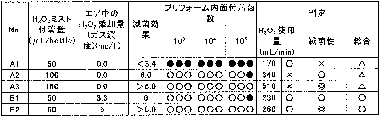
「H2O2ミスト付着量」の欄は、過酸化水素ミストがボトルの内面に付着した量を示す。
「エア中のH2O2添加量」の欄は、エアリンスの熱風中に添加した過酸化水素のガス濃度を示す。
「滅菌効果」の欄は、B.subtilis胞子(芽胞)についてのLRV(Logarithmic reduction value)を示す。
「プリフォーム内面付着菌数」の欄は、各ボトルA1、A2、A3、B1、B2の成形前にそれらのプリフォーム内面に付着させた菌数を示し、「○」は滅菌されたことを示し、「●」は殺菌不良であることを示す。
「判定」の欄中、「H2O2使用量」の欄は過酸化水素の使用量と、この使用量が適正量であるか否かを示し、「○」は適正な消費量であることを表し、「×」は消費量が多すぎることを表す。
また、「滅菌性」の欄は、滅菌効果(LRV)が「6」よりも大きいものを「◎」、「6」を「○」、「6未満」であるものを「×」として表す。「総合」の欄は、過酸化水素の使用量と滅菌性の双方が良好であるものを「○」として表し、いずれか一方でも不良「×」であるものを△として表す。
表2から明らかなように、従来法によれば、過酸化水素の使用量を340mL/min~510mL/minの大容量にしなければ滅菌効果LRV=6を得ることができないが、本発明の方法によれば、過酸化水素の使用量を230mL/min~260mL/min程度の少量にしても従来法と同程度の滅菌効果LRV=6を得ることができる。すなわち、従来の過酸化水素の使用量を1/2~1/3程度まで低減しても従来と同様な滅菌効果を得ることができる。
上記実施の形態3に係る方法を実施するための装置は、図21に示すように構成される。
図21に示すように、この殺菌装置は、口部1aを有する有底筒状のプリフォーム6(図20A参照)を所定の間隔で順次供給するプリフォーム供給機208と、ブロー成形機209と、成形されたボトル1に過酸化水素ミストαを接触させてボトル1を殺菌する殺菌手段としてのボトル殺菌機210と、殺菌されたボトル1を洗浄し、その後飲料等の内容物をボトル1に充填、密封する充填部としての充填機211とを備える。
プリフォーム供給機208から充填機211に至る間には、所定の搬送手段によって搬送路が形成され、搬送路上にはプリフォーム6やボトル1を保持しつつ搬送するグリッパー28(図17参照)等が設けられている。
プリフォーム供給機208は、プリフォーム6をブロー成形機209に所定の間隔で順次供給するプリフォームコンベア212を備える。プリフォーム6は、プリフォームコンベア212を通ってブロー成形機209内に送られる。
ブロー成形機209は、上記プリフォームコンベア212によって搬送されるプリフォーム6を加熱する加熱部213と、加熱されたプリフォーム6をボトル1に加熱成形する成形部214とを備える。
ブロー成形機209内には、上記プリフォームコンベア212の終端でプリフォーム6を受け取ってボトル1に成形し、次のボトル殺菌機210へとボトル1を搬送するための搬送手段が設けられ、その搬送路上に加熱部213、成形部214等が配置される。
搬送手段は、プリフォームコンベア212の終端から加熱部213へとプリフォーム6を搬送する第一のホイール215,216,217,218の列と、加熱部213内でプリフォーム6を走行させるコンベア219と、加熱されたプリフォーム6をこのコンベア219から受け取って成形部214へと送り、そこで成形されたボトル1を次のボトル殺菌機210へと送る第二のホイール220,221,222,217の列とを具備する。第一のホイール215,216,217,218の列と第二のホイール220,221,222,217の列との間では必要に応じてホイール217が共用される。
プリフォーム6は、プリフォームコンベア212によってブロー成形機209内に送り込まれた後、第一のホイール215,216,217,218の列を経てコンベア219に受け取られ、このコンベア219によって加熱部213内を往復移動する。加熱部213の壁面には、図示しないヒータが設けられており、コンベア219によって搬送されるプリフォーム6がこのヒータによって加熱される。加熱部213で加熱されたプリフォーム6は、第二のホイール220,221,222,217の列に受け取られ成形部214に至る。
成形部214は、ホイール221の回りに、加熱されたプリフォーム6をボトル1に成形するための金型18(図20A参照)と、加熱されたプリフォーム6の内部に気体を吹き込むブローノズル19(図20A参照)とを備える。
金型18は、図20Aに示したように、ボトル1の口部1aを成形する金型上部18aと、胴部1bを成形する金型中央部18bと、底部1cを成形する金型底部18cとを備える。金型18のこれら各部18a、18b、18cが組み合わされ、ブローノズル19からプリフォーム6内に空気等の気体が吹き込まれることによって、金型18の内部でボトル1が成形される。金型18は、プリフォーム6と一体的にホイール221の周方向に移動しつつ、プリフォーム6からボトル1を成形するようになっている。
プリフォーム6は、プリフォーム供給機208の加熱部213で加熱され、ブロー成形機209の金型18でボトル1に成形される際に冷却されるが、金型18から排出されたボトル1は成形時の残熱により上記予備成形温度を保ったままホイール222,217の回りを走行する。
上記ブロー成形機209の成形部214からボトル1が次のボトル殺菌機210へと至る箇所には、温度検査部238が設けられ、この温度検査部238内にホイール223,224,225の列が設けられる。
このうち上記ホイール217に接するホイール223の外周に温度センサ46,46が図20Bに示したように配置される。ホイール223に中間ホイール224を介して接する下流側のホイール225にはエア搬送装置等の排出用コンベア295が接続される。上記温度センサ46,46により予備成形温度に達しないと判別されたボトル1がこの排出用コンベア295から搬送路外に排出される。上記温度センサ46,46により予備成形温度に達したものと判別されたボトル1は、引き続き搬送路内を走行し、次のボトル殺菌機210へと到る。
ボトル殺菌機210は、上記温度検査されたボトル1を搬送する手段として第三のホイール226,227の列と、ボトル1に殺菌剤である過酸化水素の凝結ミストαを供給する凝結ミスト供給手段としての噴霧管59とを備える。
噴霧管59は、一本であっても複数本であってもよく、第三のホイール226,227の列中、所定のホイールの周囲に沿って定位置に固定される。図示例では終端のホイール227の回りに設置されるが、他のホイールの回りに設置することも可能である。
過酸化水素の凝結ミストαは、図10に示したミスト生成装置61によって噴霧し加熱した過酸化水素を凝結させることにより生成される。ボトル1はホイール227の回りをその口部1aを上に向けた状態で搬送され、その搬送路の上方において噴霧管59の下端がボトル1の口部1aに向かって開口する。噴霧管59内に送られた過酸化水素の凝結ミストαは、噴霧管59の下端の開口からボトル1の口部1aに向かって連続して吹き出る。そして、吹き出た過酸化水素の凝結ミストαは走行するボトル1の口部1aからボトル1内へ流入してボトル1の内面を殺菌し、他の過酸化水素の凝結ミストαはボトル1外へと流れてボトル1の外面を殺菌する。
この噴霧管59から吐出される過酸化水素の凝結ミストαがボトル1に付着する量は、上述したとおりである。
噴霧管59から過酸化水素の凝結ミストαが供給されるボトル1は、適正に殺菌処理されたうえで次の充填機211に搬送される。
充填機211は、上記ボトル殺菌機210内で殺菌されたボトル1を搬送する手段として第四のホイール229,230,231,232,233,234,235,236の列を有する。この第四のホイール229,230,231,232,233,234,235,236の列に沿って、過酸化水素の凝結ミストαが供給されたボトル1にエアリンス処理を行うエアリンス部239と、エアリンス後のボトル1を洗浄する洗浄部240と、洗浄後のボトル1に内容物を充填するためのフィラー241と、内容物が充填されたボトル1にキャップ(図示せず)を取り付けて密封するためのキャッパー242とが順に設けられる。
エアリンス部239は、ホイール229の回りにノズル64(図20D参照)を備える。このノズル64からボトル1内に無菌化された熱風γと共に過酸化水素ガスβが吹き込まれる(図20D参照)。
ノズル64は、ホイール229の周りを搬送されるボトル1と1:1に対応するように設けられており、図17に示したように、各ノズル64はホイール229の回りに取り付けられてボトル1と一体的にホイール229の周方向に移動する。
図17では、各ノズル64はボトル1外に出た状態でボトル1内に熱風γ及び過酸化水素ガスβを吹き込むようになっているが、各ノズル64を上下動可能に設け、熱風γ及び過酸化水素ガスβをボトル1内に吹き込む時に、図20Dに示すように、ボトル1内に侵入させることも可能である。
ノズル64から吹き出す熱風γ及び過酸化水素ガスβは、図17の説明において述べたと同様にして生成される。
このように、ボトル1内に無菌化した熱風γ及び過酸化水素ガスβが供給されエアリンス処理が行われることにより、ボトル1がその内面から加熱され、過酸化水素の凝結ミストα及び過酸化水素ガスβによる殺菌効果が高まる。また、熱風γ中に含まれる過酸化水素のガスβにより、上記噴霧管59から供給される過酸化水素の凝結ミストαによる殺菌が不十分であった例えばボトル1内の底部1cがより確実に殺菌される。
なお、熱風γ及び過酸化水素ガスβの吹き込み時間は、ボトル1の内部に漂っている過酸化水素の凝結ミストαをすべて排出でき、かつ過酸化水素の凝結ミストαによる殺菌不良を補うことができる範囲で行えばよい。熱風γ及び過酸化水素ガスβの吹き込み時間は例えば20秒である。
洗浄部240は、ホイール231の回りに設けられるボトル1の上下を反転させる図示しない反転機構と、ボトル1に加熱された無菌水を供給するノズル7(図20E参照)とを備える。ノズル7はホイール231によって搬送されるボトル1と1:1に対応するようにホイール231の周りに設けられており、各ノズル7はボトル1と一体的にホイール231の周方向に移動する。洗浄部240は、必要に応じて設けられ、省略することも可能である。
なお、フィラー241及びキャッパー242は公知の装置と同様で良いため、説明を省略する。
また、この殺菌装置はチャンバー243で囲まれており、チャンバー243内は無菌ゾーン、非無菌ゾーン、及び無菌ゾーンと非無菌ゾーンの中間に位置するグレーゾーンに仕切られている。そして、プリフォーム供給機208、成形機209及び温度検査部238は非無菌ゾーンに、ボトル殺菌機210はグレーゾーンに、充填機211は無菌ゾーンにそれぞれ配置されている。
次に、図1及び図2を参照して殺菌装置の動作を説明する。
まず、プリフォームコンベア212によってプリフォーム6がブロー成形機209内に供給される。ブロー成形機209内に供給されたプリフォーム6は第一のホイール215,216,217,218の列を介して加熱部213へと搬送される。
加熱部213においてプリフォーム6は、コンベア219によって搬送され、搬送中にプリフォーム6の全体の温度が成形に好適な温度域に上昇するように加熱される。
加熱部213で加熱されたプリフォーム6は、第二のホイール220,221の列によって成形部214に搬送される。そして、プリフォーム6は、搬送されつつ成形部214においてプリフォーム6と一体的に移動する金型18及びブローノズル19によりボトル1に成形される(図20A参照)。
殺菌装置の成形部214では略所定の温度に維持される金型18によって成形される。この所定の温度は、例えば後述するボトル1への過酸化水素の凝結ミストαの供給時におけるボトル1の温度や、ボトル1の材質、形状などに応じて適宜設定される。所定の温度は、例えば60℃~80℃である。
成形されたボトル1は、第二のホイール221,222,217の列から温度検査部238のホイール223,224,225へと受け渡される。そして、ホイール223の回りを走行する際にボトル1の表面温度が所定の予備加熱温度に達しているか否かを判別され、所定の予備加熱温度に達していないボトル1が不良品としてホイール225から排出用コンベア295によって搬送路外に排出される。所定の予備加熱温度に達しているボトル1は良品としてホイール226の回りへと引き続いて走行する。
良品のボトル1は、第三のホイール226,227の列へと受け渡され、この第三のホイール226,227の列によってボトル殺菌機210内を走行する。
ボトル殺菌機210では、ボトル1に噴霧管59から上述した過酸化水素の凝結ミストαが所定の流量で供給される(図20B参照)。ボトル1の搬送時は、噴霧管59から過酸化水素の凝結ミストαが供給され続ける。そのため、ホイール227によって噴霧管59の下をボトル1が通過することで、ボトル1の内外面に過酸化水素の凝結ミストαが数秒間吹き付けられる。ボトル殺菌機210に至ったボトルはその表面温度が50℃以上であることから、過酸化水素の凝結ミストαによって適正に殺菌処理される。
殺菌されたボトル1は、第三のホイール226,227の列から第四のホイール229,230,231,232,233,234,235,236の列へと受け渡され、第四のホイール229,230,231,232,233,234,235,236の列によって充填機211内を走行する。
充填機211においてボトル1はまずエアリンス部239に搬送される。エアリンス部239では、ホイール229の周りでボトル1の内部にノズル64が挿入され、ボトル1内に熱風γ及び過酸化水素ガスβが供給されエアリンス処理が行われる(図20D参照)。
エアリンス後に、ボトル1は、洗浄部240に搬送される。洗浄部240においてボトル1は、図示しない反転機構によりホイール231の周りで上下が反転され、下向きになった口部1aからボトル1内にノズル7が挿入され、ノズル7から加熱された無菌水wがボトル1内に供給される(図20E参照)。これにより、ボトル1の内部に残留している過酸化水素が洗い流される。なお。無菌水wの温度は60℃~70℃程度であるが、常温でもよい。
無菌水wによる洗浄の後、ボトル1は反転機構により口部1aが上を向く状態に戻される。
この洗浄部240は省略することも可能である。
その後、ボトル1には、フィラー241により飲料等の滅菌処理された内容物が充填される。内容物が充填されたボトル1は、キャッパー242によりキャップ(図示せず)が取り付けられて密封され、チャンバー243の出口から排出される。上述したようにフィラー241及びキャッパー242は公知の装置であるため、ボトル1への内容物の充填方法及びボトル1の密封方法の説明は省略する。
<実施の形態4>
図22に示すように、この実施の形態4における容器の殺菌装置では、上記実施の形態3における容器の殺菌装置のプリフォーム供給機208と、ブロー成形機209とが省略され、代わりに予備加熱装置296が設けられている。
図22に示すように、この実施の形態4における容器の殺菌装置では、上記実施の形態3における容器の殺菌装置のプリフォーム供給機208と、ブロー成形機209とが省略され、代わりに予備加熱装置296が設けられている。
予備加熱装置296に対応する箇所には、ボトル1の搬送路となるホイール276,277,278の列が設けられる。
これらのホイール276,277,278の列における最上流側のホイール276に、例えばエア搬送装置279が接続され、成形済みのボトル1が順に供給される。ボトル1は図4に示したグリッパー28と同様なグリッパーによってホイール276,277,278の回りを搬送される。
これら各ホイール276,277,278の回りには、ボトル1が通過するトンネル状の箱体280が設置される。各箱体280には、図17に示したと同様な熱風供給装置から熱風が供給される。各箱体280内に吹き込まれた熱風は、箱体280内を通過するボトル1に向かって流れ、ボトル1の予備加熱を行う。この予備加熱によりボトル1は50℃以上に昇温する。
この後、ボトル1は、殺菌処理のためボトル殺菌機210へと向かうが、その前に表面温度が所定の予備殺菌温度に到達しているか否か温度検査部238において検査される。
温度検査部238は、実施の形態3におけるものと同様な構成であり、予備加熱装置296におけるホイール278とボトル殺菌機210のホイール227との間に介在するホイール223,224,225,226の列を具備する。予備加熱装置296で予備加熱されたボトル1は、ホイール223の回りを走行する際にその表面温度が所定の予備加熱温度に達しているか否かを判別される。所定の予備加熱温度に達していないボトル1は不良品としてホイール225から排出用コンベア295によって搬送路外に排出される。所定の予備加熱温度に達しているボトル1は良品としてホイール226の回りへと引き続き走行する。
なお、この温度検査部238は必要に応じて設けられるもので、場合によっては省略可能である。
温度検査を経たボトル1は、ボトル殺菌機210へと向かう。ボトル1は予備加熱されていることから、ボトル殺菌機210で供給される過酸化水素の凝結ミストによる殺菌効果が向上する。
ボトル殺菌機210以降は実施の形態3の殺菌装置と同様な構成であるから、その詳細な説明は省略する。
<実施の形態5>
図23に示すように、この実施の形態5における容器の殺菌装置では、上記実施の形態4における予備加熱装置296とは異なる構成の予備加熱装置297が設けられる。
図23に示すように、この実施の形態5における容器の殺菌装置では、上記実施の形態4における予備加熱装置296とは異なる構成の予備加熱装置297が設けられる。
すなわち、実施の形態4におけるホイール277に代えて他のホイール281が設けられ、このホイールの回りに図11に示した熱風供給装置と同様な熱風供給装置が設けられる。
この熱風供給装置による予備加熱によりボトル1は50℃以上に昇温する。
この後、ボトル1は、殺菌処理のためボトル殺菌機210へと向かうが、その前に表面温度が所定の予備殺菌温度に到達しているか否か温度検査部238において検査される。
温度検査部238は、実施の形態3におけるものと同様な構成であり、予備加熱装置297におけるホイール278とボトル殺菌機210のホイール227との間に介在するホイール223,224,225,226の列を具備する。予備加熱装置297で予備加熱されたボトル1は、ホイール223の回りを走行する際にその表面温度が所定の予備加熱温度に達しているか否かを判別される。所定の予備加熱温度に達していないボトル1は不良品としてホイール225から排出用コンベア295によって搬送路外に排出される。所定の予備加熱温度に達しているボトル1は良品としてホイール226の回りへと引き続き走行する。
なお、この温度検査部238は必要に応じて設けられるもので、場合によっては省略可能である。
温度検査を経たボトル1は、ボトル殺菌機210へと向かう。ボトル1は予備加熱されていることから、ボトル殺菌機210で供給される過酸化水素の凝結ミストによる殺菌効果が向上する。
ボトル殺菌機210以降は実施の形態4の殺菌装置と同様な構成であるから、その詳細な説明は省略する。
なお、本発明は、上述した実施の形態に限定されることなく種々の形態にて実施可能である。
例えば、本発明の飲料充填装置が適用される容器はPETボトルに限定されず、種々の樹脂製容器に適用することができる。また、飲料も単なる液体だけでなく、粒状物、塊等を含んだものや、高粘度のものも充填可能である。ボトルの成形もインジェクションブローに限定されず、ダイレクトブロー、射出成形等各種の成形方法によって成形可能である。
また、無菌水によるボトルの洗浄は、無菌水を流しつつ行うものに限定されない。また、プリフォームやボトルを搬送する搬送手段は、上述したホイール搬送装置に限定されない。ボトルが成形された順に所定の搬送速度で搬送可能な種々の搬送装置、例えばエア搬送装置、ベルト搬送装置、バケット搬送装置を使用することができる。
また、本発明の飲料充填方法及び装置において使用する殺菌方法および装置は、次のような態様とすることができる。
(1)態様1
予備加熱した容器を走行させながら容器の温度検査を行って、所定の温度に達しない容器を除去し、所定の温度に達した容器を引き続き走行させながら、その口部に向かって過酸化水素の凝結ミストを定位置に置かれた噴霧管から吹き付け、次いで、容器の口部にノズルを追従させながら、過酸化水素のガスをノズルから容器内に吹き込む容器の殺菌方法。
(1)態様1
予備加熱した容器を走行させながら容器の温度検査を行って、所定の温度に達しない容器を除去し、所定の温度に達した容器を引き続き走行させながら、その口部に向かって過酸化水素の凝結ミストを定位置に置かれた噴霧管から吹き付け、次いで、容器の口部にノズルを追従させながら、過酸化水素のガスをノズルから容器内に吹き込む容器の殺菌方法。
態様1によれば、所定の温度に達した容器のみを殺菌部へと走行させて過酸化水素によって適正に殺菌することができ、従って、殺菌不良の容器への内容物の充填を防止することができる。また、過酸化水素の凝結ミストの供給後に過酸化水素のガスを供給するので、無菌包装体の生産性を高めるために容器の走行速度を大きくしても過酸化水素の凝結ミストあるいは過酸化水素の流量、消費量を増大することなく容器を適正に殺菌することができる。
(2)態様2
上記態様1に記載の容器の殺菌方法において、予備加熱は容器の成形時の残熱によるものとした容器の殺菌方法。
(2)態様2
上記態様1に記載の容器の殺菌方法において、予備加熱は容器の成形時の残熱によるものとした容器の殺菌方法。
態様2によれば、予備加熱のための熱源を別途用意することなく容器を予備加熱することができ、従って熱エネルギーの効率的な使用が可能になる。
(3)態様3
上記態様1又は態様2に記載の容器の殺菌方法において、過酸化水素のガスは、過酸化水素の凝結ミストを熱風によって加熱しガス化したものとする容器の殺菌方法。
(3)態様3
上記態様1又は態様2に記載の容器の殺菌方法において、過酸化水素のガスは、過酸化水素の凝結ミストを熱風によって加熱しガス化したものとする容器の殺菌方法。
態様3によれば、過酸化水素の適正な濃度のガスを結露させることなく容器に供給することができる。従って、容器への過酸化水素のボタ落ち等を防止しつつ容器を適正に殺菌することができる。
(4)態様4
態様1乃至態様3のいずれかに記載の容器の殺菌方法において、過酸化水素のガスを容器内に吹き込んだ後に、容器内を無菌水によって洗浄することを特徴とする容器の殺菌方法。
(4)態様4
態様1乃至態様3のいずれかに記載の容器の殺菌方法において、過酸化水素のガスを容器内に吹き込んだ後に、容器内を無菌水によって洗浄することを特徴とする容器の殺菌方法。
態様4によれば、殺菌に使用された過酸化水素を容器から効率よく除去することができる。
(5)態様5
容器を所定の搬送路に沿って搬送する搬送手段を有し、この搬送路を走行する容器を所定の温度まで予備加熱する予備加熱手段と、予備加熱された容器が所定の温度まで達しているか否かを検査する温度センサと、所定の温度に達しない容器を搬送路から除去する除去手段と、搬送路を走行する所定の温度に達した容器の口部に向かって、過酸化水素の凝結ミストを定位置から吹き付ける噴霧管と、搬送路を走行する容器に追従しながら過酸化水素のガスを容器内に吹き込むノズルとが上記搬送路に沿って配置された容器の殺菌装置。
(5)態様5
容器を所定の搬送路に沿って搬送する搬送手段を有し、この搬送路を走行する容器を所定の温度まで予備加熱する予備加熱手段と、予備加熱された容器が所定の温度まで達しているか否かを検査する温度センサと、所定の温度に達しない容器を搬送路から除去する除去手段と、搬送路を走行する所定の温度に達した容器の口部に向かって、過酸化水素の凝結ミストを定位置から吹き付ける噴霧管と、搬送路を走行する容器に追従しながら過酸化水素のガスを容器内に吹き込むノズルとが上記搬送路に沿って配置された容器の殺菌装置。
態様5によれば、所定の温度に達した容器のみを殺菌部へと走行させて過酸化水素によって適正に殺菌することができ、従って、殺菌不良の容器への内容物の充填を防止することができる。また、過酸化水素の凝結ミストの供給後に過酸化水素のガスを供給するので、無菌包装体の生産性を高めるために容器の走行速度を大きくしても過酸化水素の凝結ミスト(M)あるいは過酸化水素の流量、消費量を増大することなく容器を適正に殺菌することができる。
(6)態様6
上記態様5に記載の容器の殺菌装置において、搬送路の噴霧管よりも上流側に設けられた容器の成形機が予備加熱手段を兼ねる容器の殺菌装置。
(6)態様6
上記態様5に記載の容器の殺菌装置において、搬送路の噴霧管よりも上流側に設けられた容器の成形機が予備加熱手段を兼ねる容器の殺菌装置。
態様6によれば、予備加熱を容器の成形時の残熱によるものとすることができ、従って、予備加熱のための熱源を別途用意することなくエネルギーの効率的な使用が可能になる。
(7)態様7
上記態様5に記載の容器の殺菌装置において、噴霧管よりも上流側に、容器の予備加熱装置が設けられた容器の殺菌装置。
(7)態様7
上記態様5に記載の容器の殺菌装置において、噴霧管よりも上流側に、容器の予備加熱装置が設けられた容器の殺菌装置。
態様7によれば、容器の予備加熱をより正確に行うことができる。
(8)態様8
上記態様5乃至態様7のいずれかに記載の容器の殺菌装置において、過酸化水素のガスは、過酸化水素の凝結ミストを熱風によって加熱することにより生成する容器の殺菌装置。
(8)態様8
上記態様5乃至態様7のいずれかに記載の容器の殺菌装置において、過酸化水素のガスは、過酸化水素の凝結ミストを熱風によって加熱することにより生成する容器の殺菌装置。
態様8によれば、過酸化水素の適正な濃度のガスを結露させることなく容器に供給することができる。従って、容器への過酸化水素のボタ落ち等を防止しつつ容器を適正に殺菌することができる。
(9)態様9
上記態様5乃至態様8のいずれかに記載の容器の殺菌装置において、過酸化水素のガスを吹き付けるノズルよりも下流側に、容器内を無菌水によって洗浄する洗浄手段が設けられた容器の殺菌装置。
(9)態様9
上記態様5乃至態様8のいずれかに記載の容器の殺菌装置において、過酸化水素のガスを吹き付けるノズルよりも下流側に、容器内を無菌水によって洗浄する洗浄手段が設けられた容器の殺菌装置。
態様9によれば、殺菌に使用された過酸化水素を容器から効率よく除去することができる。
1…ボトル
1a…ボトルの首部
1d…天面
5…サポートリング
6…プリフォーム
7…成形部
8…検査部
8a,9a…チャンバー
9…殺菌部
10…充填部
14a…ターンテーブル
19a,19b,36a…ホイール
28,37…グリッパー
42…ピストン・シリンダ装置
45,48,50,52,…カメラ
46…温度センサ
53a…可動カム部
84…ブロア
79…雰囲気遮断チャンバー
90…エアノズル
96…エアリンス部
97…ヒータ
a…飲料
w…温水
α…過酸化水素の凝結ミスト
β…過酸化水素のガス
γ…無菌の熱風
S1…サーボモータ
1a…ボトルの首部
1d…天面
5…サポートリング
6…プリフォーム
7…成形部
8…検査部
8a,9a…チャンバー
9…殺菌部
10…充填部
14a…ターンテーブル
19a,19b,36a…ホイール
28,37…グリッパー
42…ピストン・シリンダ装置
45,48,50,52,…カメラ
46…温度センサ
53a…可動カム部
84…ブロア
79…雰囲気遮断チャンバー
90…エアノズル
96…エアリンス部
97…ヒータ
a…飲料
w…温水
α…過酸化水素の凝結ミスト
β…過酸化水素のガス
γ…無菌の熱風
S1…サーボモータ
Claims (23)
- 加熱されたプリフォームからブロー成形によりボトルを成形し、成形後にボトルを検査し、検査後上記プリフォームに加えた熱が残留しているうちにボトルに過酸化水素のミスト又はガスを吹き付け、しかる後にボトルに飲料を充填して密封することを特徴とする飲料充填方法。
- 請求項1に記載の飲料充填方法において、ボトルに過酸化水素のミスト又はガスを吹き付けた後にボトルを無菌エアでエアリンスし、しかる後にボトルに飲料を充填して密封することを特徴とする飲料充填方法。
- 請求項1に記載の飲料充填方法において、ボトルに過酸化水素のミスト又はガスを吹き付けた後に、ボトルを加熱した無菌水でリンスし、しかる後にボトルに飲料を充填して密封することを特徴とする飲料充填方法。
- 請求項1に記載の飲料充填方法において、ボトルをエアリンスした後に、無菌水リンスし、しかる後にボトルに飲料を充填して密封することを特徴とする飲料充填方法。
- 請求項4に記載の飲料充填方法において、過酸化水素ガスを含んだ無菌エアでボトルをエアリンスした後に、無菌水リンスし、しかる後にボトルに飲料を充填して密封することを特徴とする飲料充填方法。
- 請求項1乃至請求項35のいずれかに記載の飲料充填方法において、成形されたボトルをその密封に至るまで連続走行させる走行路を設け、この走行路を各々が回りにグリッパーを備えたホイールの列によって形成し、グリッパーが各ホイールの回りでボトルの首部を把持して旋回すると共にボトルを上流側ホイールから下流側のホイールへと受け渡すようにしたことを特徴とする飲料充填方法。
- 請求項1に記載の飲料充填方法において、加熱されたプリフォームからブロー成形によりボトルを成形する工程からボトルに飲料を充填して密封するまでの全工程を、ボトルを連続走行させながら行い、上記ボトルを成形した後殺菌する前に、プリフォーム加熱時の熱が残留したボトルの温度を検査し、この温度が所定値に達していないボトルを排除し、所定値に達したボトルに対してのみ上記殺菌及び充填を行うようにしたことを特徴とする飲料充填方法。
- 請求項7に記載の飲料充填方法において、温度検査のほかボトルの胴部を撮像して検査することを特徴とする飲料充填方法。
- 請求項7に記載の飲料充填方法において、温度検査のほかボトルの底部を撮像して検査することを特徴とする飲料充填方法。
- 請求項7に記載の飲料充填方法において、温度検査のほかボトルの首部の天面を撮像して検査することを特徴とする飲料充填方法。
- 請求項7に記載の飲料充填方法において、温度検査のほかボトルの首部のサポートリングを撮像して検査することを特徴とする飲料充填方法。
- 加熱されたプリフォームからブロー成形によりボトルを成形する成形部と、成形部で成形されたボトルを過酸化水素のミスト又はガスで殺菌する殺菌部と、殺菌部で殺菌されたボトルに飲料を充填し密封する充填部とが連結され、上記成形部から上記殺菌部を経て上記充填部へとボトルを走行路上で連続走行させる走行手段が設けられ、上記殺菌部から上記充填部に至る箇所がチャンバーで覆われた飲料充填装置において、上記成形部で成形されたボトルについて所定の検査を行う検査部が、上記成形部と上記殺菌部との間にこれらに連結されるように設けられ、この検査部には、検査により不良と判断されたボトルを上記走行路から排除する排除手段と、検査部内を上記成形部内及び上記殺菌部内よりも陽圧化する陽圧化手段とが設けられ、上記走行手段は、上記成形部から上記充填部へと列状に配置されたホイールと、各ホイールの回りでボトルの首部を把持して旋回すると共にボトルを上流側ホイールから下流側のホイールへと受け渡すグリッパーとを具備し、上記グリッパーは、上記プリフォームに加えられボトルに残留した熱が上記殺菌部でのボトルの殺菌に必要な程度まで保たれるよう走行速度が制御されるようにしたことを特徴とする飲料充填装置。
- 請求項12に記載の飲料充填装置において、殺菌部と充填部との間に、殺菌部で殺菌されたボトルを無菌エアでエアリンスするエアリンス部が設けられたことを特徴とする飲料充填装置。
- 請求項12に記載の飲料充填装置において、殺菌部と充填部との間に殺菌部で殺菌されたボトルを加熱された無菌水でリンスする無菌水リンス部が設けられたことを特徴とする飲料充填装置。
- 請求項13に記載の飲料充填装置において、エアリンス部と充填部との間に無菌水リンス部が設けられたことを特徴とする飲料充填装置。
- 請求項15に記載の飲料充填装置において、エアリンス部で過酸化水素ガスを含んだエアをボトルに吹き付けるようにしたことを特徴とする飲料充填装置。
- 請求項13に記載の飲料充填装置において、上記ホイールが所望の数の列に区分され、列ごとに別個のサーボモータで駆動されるようにしたことを特徴とする飲料充填装置。
- 請求項13に記載の飲料充填装置において、上記検査部にはボトルの温度を検出してボトルの良否を判別する温度検査手段が設けられていることを特徴とする飲料充填装置。
- 請求項13に記載の飲料充填装置において、上記検査部内を走行するグリッパーには、つや消し表面加工が施されていることを特徴とする飲料充填装置。
- 請求項13に記載の飲料充填装置において、上記ボトル成形部側のホイールと、このホイールに隣接する上記検査部側のホイールとの間で、一方のホイールが停止した時にグリッパー同士の干渉を防止するグリッパー干渉防止手段が設けられていることを特徴とする飲料充填装置。
- 請求項13に記載の飲料充填装置において、検査部のチャンバーと殺菌部のチャンバーとの間には雰囲気遮断チャンバーが設けられ、検査部のチャンバー内にはエアの供給手段によって清浄なエアが供給されるようにし、雰囲気遮断チャンバーからは排気手段によって排気されるようにしたことを特徴とする飲料充填装置。
- 請求項21に記載の飲料充填装置において、上記殺菌部のチャンバーが上記雰囲気遮断チャンバーに接する箇所に、上記殺菌部のチャンバー内から過酸化水素のミスト又はガスをチャンバー外に排出する排気手段が設けられていることを特徴とする飲料充填装置。
- 請求項21に記載の飲料充填装置において、上記殺菌部のチャンバーが上記雰囲気遮断チャンバーに接する箇所に、エアカーテンを形成するエアノズルが配置されていることを特徴とする飲料充填装置。
Priority Applications (10)
| Application Number | Priority Date | Filing Date | Title |
|---|---|---|---|
| CN200980117979.8A CN102099253B (zh) | 2008-05-20 | 2009-05-19 | 饮料填充方法和装置 |
| US12/993,727 US9108835B2 (en) | 2008-05-20 | 2009-05-19 | Beverage filling method and apparatus |
| EP20090750560 EP2279952B1 (en) | 2008-05-20 | 2009-05-19 | Method and apparatus for packing beverage |
| US14/109,391 US9593004B2 (en) | 2008-05-20 | 2013-12-17 | Beverage filling apparatus |
| US14/142,025 US11214395B2 (en) | 2008-05-20 | 2013-12-27 | Beverage filling method and apparatus |
| US14/141,980 US10112733B2 (en) | 2008-05-20 | 2013-12-27 | Beverage filling method and apparatus |
| US14/143,707 US9617136B2 (en) | 2008-05-20 | 2013-12-30 | Beverage filling method and apparatus |
| US14/143,637 US9617135B2 (en) | 2008-05-20 | 2013-12-30 | Beverage filling method and apparatus |
| US15/445,110 US11702236B2 (en) | 2008-05-20 | 2017-02-28 | Beverage filling method and apparatus |
| US15/445,154 US20170166342A1 (en) | 2008-05-20 | 2017-02-28 | Beverage filling method and apparatus |
Applications Claiming Priority (10)
| Application Number | Priority Date | Filing Date | Title |
|---|---|---|---|
| JP2008-131978 | 2008-05-20 | ||
| JP2008131978A JP5286929B2 (ja) | 2008-05-20 | 2008-05-20 | 容器の殺菌方法及び装置 |
| JP2008334563A JP5332603B2 (ja) | 2008-12-26 | 2008-12-26 | 飲料充填方法及び装置 |
| JP2008-334563 | 2008-12-26 | ||
| JP2009026036A JP5332672B2 (ja) | 2009-02-06 | 2009-02-06 | 飲料充填方法及び装置 |
| JP2009-026035 | 2009-02-06 | ||
| JP2009026035A JP5402038B2 (ja) | 2009-02-06 | 2009-02-06 | 飲料充填装置 |
| JP2009-026036 | 2009-02-06 | ||
| JP2009-033813 | 2009-02-17 | ||
| JP2009033813A JP2010189023A (ja) | 2009-02-17 | 2009-02-17 | 飲料充填装置 |
Related Child Applications (6)
| Application Number | Title | Priority Date | Filing Date |
|---|---|---|---|
| US12/993,727 A-371-Of-International US9108835B2 (en) | 2008-05-20 | 2009-05-19 | Beverage filling method and apparatus |
| US14/109,391 Division US9593004B2 (en) | 2008-05-20 | 2013-12-17 | Beverage filling apparatus |
| US14/141,980 Division US10112733B2 (en) | 2008-05-20 | 2013-12-27 | Beverage filling method and apparatus |
| US14/142,025 Division US11214395B2 (en) | 2008-05-20 | 2013-12-27 | Beverage filling method and apparatus |
| US14/143,707 Division US9617136B2 (en) | 2008-05-20 | 2013-12-30 | Beverage filling method and apparatus |
| US14/143,637 Division US9617135B2 (en) | 2008-05-20 | 2013-12-30 | Beverage filling method and apparatus |
Publications (1)
| Publication Number | Publication Date |
|---|---|
| WO2009142198A1 true WO2009142198A1 (ja) | 2009-11-26 |
Family
ID=41340131
Family Applications (1)
| Application Number | Title | Priority Date | Filing Date |
|---|---|---|---|
| PCT/JP2009/059183 Ceased WO2009142198A1 (ja) | 2008-05-20 | 2009-05-19 | 飲料充填方法及び装置 |
Country Status (4)
| Country | Link |
|---|---|
| US (8) | US9108835B2 (ja) |
| EP (6) | EP2657184B9 (ja) |
| CN (6) | CN103588154B (ja) |
| WO (1) | WO2009142198A1 (ja) |
Cited By (12)
| Publication number | Priority date | Publication date | Assignee | Title |
|---|---|---|---|---|
| JP2011178402A (ja) * | 2010-02-26 | 2011-09-15 | Dainippon Printing Co Ltd | 酸性飲料充填方法及び装置 |
| WO2011135598A1 (en) * | 2010-04-29 | 2011-11-03 | Sidel S.P.A. Con Socio Unico | Clamping device for clamping a plurality of capped containers and method for transferring a plurality of capped containers |
| CN103261033A (zh) * | 2010-12-16 | 2013-08-21 | 大日本印刷株式会社 | 清凉饮料的填充方法及装置 |
| JP2014221671A (ja) * | 2014-07-31 | 2014-11-27 | 大日本印刷株式会社 | 酸性飲料充填方法及び装置 |
| JPWO2015098726A1 (ja) * | 2013-12-25 | 2017-03-23 | 大日本印刷株式会社 | 飲料充填装置 |
| CN106715321A (zh) * | 2014-09-25 | 2017-05-24 | 大日本印刷株式会社 | 碳酸饮料填充方法及装置 |
| JP2017197292A (ja) * | 2017-06-29 | 2017-11-02 | 大日本印刷株式会社 | 容器殺菌装置、内容物充填システム及び内容物充填方法 |
| CN109789939A (zh) * | 2016-09-26 | 2019-05-21 | 大日本印刷株式会社 | 无菌填充机以及无菌填充方法 |
| CN110475723A (zh) * | 2017-04-07 | 2019-11-19 | 大日本印刷株式会社 | 无菌填充方法以及无菌填充机 |
| US20210094718A1 (en) * | 2019-09-30 | 2021-04-01 | Krones Ag | Modular treatment apparatus for containers |
| CN113697748A (zh) * | 2021-09-17 | 2021-11-26 | 苏州凌耀制药设备有限公司 | 一种口服液密封加盖工艺及其加盖设备 |
| JP2023143945A (ja) * | 2019-10-31 | 2023-10-06 | 三菱重工機械システム株式会社 | 飲料充填システム |
Families Citing this family (62)
| Publication number | Priority date | Publication date | Assignee | Title |
|---|---|---|---|---|
| DE102010042165A1 (de) * | 2010-10-07 | 2012-04-12 | Krones Aktiengesellschaft | Verfahren zum Behandeln wenigstens eines Behälters in einer Behälterbehandlungsanlage |
| DE102010054788A1 (de) | 2010-12-16 | 2012-06-21 | Krones Aktiengesellschaft | Vorrichtung zum Sterilisieren von Behältnissen |
| DE102011102056B4 (de) * | 2011-05-19 | 2016-05-12 | Khs Corpoplast Gmbh | Verfahren sowie Vorrichtung zum Herstellen von gefüllten Behältern aus Vorformlingen |
| DE102011055552A1 (de) * | 2011-11-21 | 2013-05-23 | Krones Ag | Innengreifendes Halteelement zur Behältersterilisation mittels Elektronenstrahlen |
| ITBO20110691A1 (it) * | 2011-12-02 | 2013-06-03 | Ativa | Linea e procedimento di imbottigliamento in ciclo continuo di contenitori in materiale termoplastico. |
| JP5201377B1 (ja) * | 2011-12-05 | 2013-06-05 | 東洋製罐株式会社 | 充填密封方法及び装置 |
| ITBO20120337A1 (it) * | 2012-06-20 | 2013-12-21 | Ima Ind Srl | Procedimento e macchina per formare capsule monouso per bevande |
| ITBO20120338A1 (it) | 2012-06-20 | 2013-12-21 | Ima Ind Srl | Procedimento e macchina per formare componenti intermedi di capsule monouso per bevande |
| DE102012218481A1 (de) * | 2012-10-10 | 2014-04-10 | Kba-Kammann Gmbh | Verfahren und Vorrichtung zum Ausrichten von Gegenständen |
| DE102012111770A1 (de) * | 2012-12-04 | 2014-06-05 | Krones Ag | Inspektionsverfahren und Inspektionsvorrichtung für Behältnisse |
| DE102013101407A1 (de) * | 2013-02-13 | 2014-08-14 | Khs Gmbh | Verfahren zum Verpacken von flüssigen Produkten unter Druck in Flaschen aus Kunststoff oder dgl. Behälter |
| DE102013101995B3 (de) * | 2013-02-28 | 2014-06-05 | Khs Gmbh | Inspektionsvorrichtung mit optischem Kanal aus Kanalelementen |
| CN105682886B (zh) * | 2013-09-18 | 2020-08-11 | 三菱重工机械系统株式会社 | 吹塑成型装置 |
| EP3070011B1 (en) * | 2013-11-11 | 2021-08-11 | Mitsubishi Heavy Industries Machinery Systems, Ltd. | Sterilization device for container |
| JP6439920B2 (ja) | 2013-11-14 | 2018-12-19 | 大日本印刷株式会社 | ボトルの殺菌方法及び装置 |
| EP2886508B1 (de) * | 2013-12-20 | 2016-04-13 | CTC Analytics AG | Betätigungsvorrichtung für Schraubdeckel |
| DE102014002530B4 (de) | 2014-02-24 | 2017-12-28 | Multitec Holdings Gmbh | Fördereinrichtung zur Förderung von Lebensmittelprodukten |
| CN105939937B (zh) | 2014-03-14 | 2019-12-20 | 大日本印刷株式会社 | 容器的杀菌方法及装置 |
| EP2942321A1 (en) * | 2014-05-05 | 2015-11-11 | Sidel S.p.a. Con Socio Unico | Bottling plant and line for conveying containers |
| JP6404612B2 (ja) | 2014-06-23 | 2018-10-10 | 株式会社細川洋行 | 内容物が無菌充填されたスパウト付きパウチの製造方法及び集積物 |
| CN104555231B (zh) * | 2015-01-14 | 2016-06-22 | 天津市华帅制药机械有限公司 | 垂直输送灌装后玻璃输液瓶的输送机设备 |
| EP3769934B1 (en) * | 2015-04-30 | 2022-02-23 | Dai Nippon Printing Co., Ltd. | Aseptic container molding method and apparatus and aseptic filling method and apparatus |
| CN104922710B (zh) * | 2015-05-29 | 2017-12-12 | 江苏新美星包装机械股份有限公司 | 一种瓶坯杀菌装置 |
| WO2017047691A1 (ja) | 2015-09-17 | 2017-03-23 | 大日本印刷株式会社 | 無菌充填装置及びその浄化方法 |
| DE102015118671A1 (de) | 2015-10-30 | 2017-05-04 | Krones Ag | Vorrichtung zum Befüllen von Behältern mit einem Füllprodukt |
| CN112079312B (zh) * | 2015-12-22 | 2022-10-21 | 大日本印刷株式会社 | 产品充填装置的洗净杀菌方法及装置 |
| JP7149685B2 (ja) * | 2016-01-18 | 2022-10-07 | ザ コカ・コーラ カンパニー | 飲料充填装置及び容器入り飲料の製造方法 |
| CN105644860B (zh) * | 2016-02-26 | 2018-08-31 | 江苏新美星包装机械股份有限公司 | 一种用于吹灌旋一体机的剔瓶机构 |
| CN113443226B (zh) * | 2016-03-08 | 2023-06-20 | 大日本印刷株式会社 | 内容物填充系统中的初始菌确认方法以及无菌性验证方法 |
| FR3051675B1 (fr) | 2016-05-25 | 2019-09-27 | Sidel Participations | Procede de traitement de corps creux et installation de fabrication de recipients integrant un tel procede |
| MY202296A (en) * | 2016-05-31 | 2024-04-23 | Dainippon Printing Co Ltd | Cap sterilizer, content filling system, and cap sterilization method |
| CN109661350B (zh) * | 2016-09-14 | 2021-12-21 | 涩谷工业株式会社 | 填充系统 |
| US10717553B2 (en) * | 2016-09-14 | 2020-07-21 | Shibuya Corporation | Filling system |
| DE102016123965A1 (de) * | 2016-12-09 | 2018-06-14 | Krones Ag | Füllvorrichtung zum Abfüllen eines Füllprodukts in einen zu befüllenden Behälter in einer Füllproduktabfüllanlage |
| CN106645024A (zh) * | 2016-12-17 | 2017-05-10 | 浙江泰林生物技术股份有限公司 | 一种基于tdlas的大量程气化h2o2浓度检测仪 |
| US11046567B2 (en) * | 2017-02-02 | 2021-06-29 | Dai Nippon Printing Co., Ltd. | Beverage aseptic filling system and carbonated beverage aseptic filling system |
| JP6380572B2 (ja) | 2017-02-20 | 2018-08-29 | 大日本印刷株式会社 | 無菌充填機のトラブル回復方法及び無菌充填機 |
| KR20240133776A (ko) | 2017-03-27 | 2024-09-04 | 리제너론 파아마슈티컬스, 인크. | 살균 방법 |
| JP6548091B2 (ja) | 2017-03-28 | 2019-07-24 | 大日本印刷株式会社 | 内容物充填システムの検証方法および内容物充填システム |
| DE102017107176A1 (de) * | 2017-04-04 | 2018-10-04 | Khs Gmbh | Anlage sowie Verfahren zum Herstellen von Verpackungsgebinden |
| US11667505B2 (en) | 2017-05-10 | 2023-06-06 | Dai Nippon Printing Co., Ltd. | Aseptic filling machine and aseptic filling method |
| IT201700089679A1 (it) | 2017-08-03 | 2019-02-03 | Gea Procomac Spa | Apparato per produrre recipienti sterili, impianto di imbottigliamento comprendente tale apparato e metodo per produrre un recipiente sterile |
| IT201700094800A1 (it) * | 2017-08-21 | 2019-02-21 | Lameplast Spa | Impianto per la produzione di contenitori, particolarmente contenitori per prodotti medicali, farmaceutici, cosmetici, alimentari o simili |
| JP6760343B2 (ja) * | 2018-08-31 | 2020-09-23 | 大日本印刷株式会社 | 無菌充填機及びその浄化方法 |
| RU2694248C1 (ru) * | 2018-12-13 | 2019-07-10 | Евгений Федорович Клинецкий | Установка для розлива напитков |
| JP6819709B2 (ja) * | 2019-03-01 | 2021-01-27 | 大日本印刷株式会社 | 容器殺菌装置、内容物充填システム、容器殺菌方法および内容物充填方法 |
| EP3730156A1 (en) * | 2019-04-25 | 2020-10-28 | Sidel Participations | Treatment machine for treating receptacles and method of operating such a treatment machine |
| MA54325A (fr) | 2019-06-05 | 2022-05-11 | Regeneron Pharma | Dispositifs et procédés pour l'administration précise de doses |
| EP4570740B1 (en) | 2019-11-21 | 2026-02-25 | Dai Nippon Printing Co., Ltd. | Aseptic filling method and aseptic filling machine |
| JP6924423B2 (ja) * | 2019-12-04 | 2021-08-25 | 大日本印刷株式会社 | キャップ殺菌装置および内容物充填システム |
| JP6944661B2 (ja) * | 2020-03-12 | 2021-10-06 | 大日本印刷株式会社 | 殺菌方法 |
| WO2021182241A1 (ja) * | 2020-03-13 | 2021-09-16 | 大日本印刷株式会社 | 無菌充填方法及び無菌充填機 |
| DE102020109455A1 (de) * | 2020-04-03 | 2021-10-07 | Khs Corpoplast Gmbh | Verfahren und Vorrichtung zum Sterilisieren von Preforms oder von daraus geformten Behältern |
| CN111844692A (zh) * | 2020-07-29 | 2020-10-30 | 山东新华医疗器械股份有限公司 | 一种塑料瓶连续生产灌装设备 |
| NO349722B1 (en) * | 2021-06-04 | 2026-04-20 | Shikoku Kakoki Co Ltd | Hot air extraction duct |
| JP7245453B1 (ja) * | 2021-10-14 | 2023-03-24 | 大日本印刷株式会社 | 内容物充填システム及び殺菌方法 |
| CN113800456B (zh) * | 2021-10-28 | 2022-12-13 | 绍兴至味食品有限公司 | 一种全自动灌装设备 |
| JP2023103051A (ja) * | 2022-01-13 | 2023-07-26 | 澁谷工業株式会社 | 容器殺菌装置 |
| EP4253309A1 (en) * | 2022-03-31 | 2023-10-04 | Sidel Participations | Filling machine with inspection system and packaging apparatus comprising such filling machine |
| USD1120314S1 (en) | 2022-11-30 | 2026-03-24 | Regeneron Pharmaceuticals, Inc. | Dose delivery device |
| CN115924230B (zh) * | 2023-02-27 | 2023-05-12 | 山东省食品药品检验研究院 | 一种食品检测包装设备 |
| US20250319644A1 (en) * | 2024-04-15 | 2025-10-16 | Discma Ag | Method of aseptically forming a container with a fluid |
Citations (9)
| Publication number | Priority date | Publication date | Assignee | Title |
|---|---|---|---|---|
| JPH08244730A (ja) * | 1995-03-10 | 1996-09-24 | Dainippon Printing Co Ltd | 容器の外面殺菌装置 |
| JPH09328113A (ja) * | 1996-06-10 | 1997-12-22 | Dainippon Printing Co Ltd | 無菌領域の滅菌方法及びこれに用いる装置 |
| JPH11291331A (ja) | 1998-04-07 | 1999-10-26 | Asahi Soft Drinks Co Ltd | 無菌容器のブロー成形、充填方法及びその装置 |
| JP2001525542A (ja) * | 1997-12-04 | 2001-12-11 | エイジーアール インターナショナル,インコーポレイテッド | 容器のバルジを検査する装置及び方法 |
| JP2003004648A (ja) * | 2001-06-19 | 2003-01-08 | Hokkai Can Co Ltd | プラスチック製ボトルの内面被膜検査装置 |
| JP2006111295A (ja) | 2004-10-13 | 2006-04-27 | Dainippon Printing Co Ltd | 容器の殺菌方法及び殺菌装置 |
| WO2007031194A1 (de) * | 2005-09-15 | 2007-03-22 | Krones Ag | Verfahren zur qualitätskontrolle von kunststoffbehältern |
| JP2007113923A (ja) * | 2005-10-18 | 2007-05-10 | Toyo Seikan Kaisha Ltd | ネックリング検査装置及びネックリング検査方法 |
| JP2008074438A (ja) * | 2006-09-20 | 2008-04-03 | Dainippon Printing Co Ltd | 容器の殺菌方法及び装置 |
Family Cites Families (82)
| Publication number | Priority date | Publication date | Assignee | Title |
|---|---|---|---|---|
| US3356212A (en) * | 1965-02-24 | 1967-12-05 | Owens Illinois Inc | Inspecting method and apparatus |
| IN153503B (ja) * | 1979-01-11 | 1984-07-21 | Nat Res Dev | |
| AU554222B2 (en) * | 1981-10-13 | 1986-08-14 | Toyo Garasu K.K. | Inspecting glass containers |
| DE3407386C2 (de) * | 1984-02-29 | 1987-02-05 | Hermann 8404 Wörth Kronseder | Inspektionsmaschine für Flaschen |
| US4952370A (en) * | 1988-05-06 | 1990-08-28 | American Sterilizer Company | Hydrogen peroxide sterilization method |
| US4992247A (en) * | 1989-05-11 | 1991-02-12 | Elopak Systems, A.G. | Container sterilization system |
| US5073708A (en) * | 1989-09-11 | 1991-12-17 | Shibuya Kogyo Co., Ltd. | Apparatus for inspecting the presence of foreign matters |
| CH679698A5 (ja) * | 1989-10-06 | 1992-03-31 | Elpatronic Ag | |
| US5258162A (en) * | 1989-11-07 | 1993-11-02 | Tetra Alfa Holdings S.A. | Method of producing a gaseous hydrogen peroxide-containing sterilization fluid |
| JPH03226444A (ja) | 1990-01-24 | 1991-10-07 | Dainippon Printing Co Ltd | 包装材料殺菌用殺菌剤ガスの製造方法及びその製造方法の実施に使用する殺菌剤ガス製造装置 |
| US5291271A (en) * | 1992-08-19 | 1994-03-01 | Owens-Brockway Glass Container Inc. | Measurement of transparent container wall thickness |
| US5308979A (en) * | 1992-08-21 | 1994-05-03 | The United States Of America As Represented By The United States Department Of Energy | Analysis of hydrogen isotope mixtures |
| US5440385A (en) * | 1993-02-05 | 1995-08-08 | Pressco Technology, Inc. | Integrated isotropic illumination source for translucent item inspection |
| DE4427870A1 (de) | 1994-08-06 | 1996-02-08 | Alfill Getraenketechnik | Verfahren und Vorrichtung zum Bedrucken von gewölbten bzw. rotationssymmetrischen Oberflächen von kontinuierlich geförderten Behältern der Getränkeindustrie |
| US5442446A (en) * | 1994-08-19 | 1995-08-15 | Owens-Brockaway Glass Container Inc. | Inspection of transparent containers |
| JP2875480B2 (ja) * | 1994-09-14 | 1999-03-31 | 日本エア・リキード株式会社 | 高純度臭化水素精製方法及び装置 |
| US5591462A (en) * | 1994-11-21 | 1997-01-07 | Pressco Technology, Inc. | Bottle inspection along molder transport path |
| US6025910A (en) * | 1995-09-12 | 2000-02-15 | Coors Brewing Company | Object inspection method utilizing a corrected image to find unknown characteristic |
| AP913A (en) * | 1996-02-09 | 2000-12-08 | Diffclean As | A method and an apparatus for surface sterilising items and a system suitable for sterilising bottles. |
| JPH10119934A (ja) * | 1996-10-23 | 1998-05-12 | Shikoku Kakoki Co Ltd | 容器殺菌装置および容器包材の殺菌方法 |
| DE19651924A1 (de) * | 1996-12-13 | 1998-06-18 | Dieter Olschewski | Behälterglasprüfverfahren und -vorrichtungen |
| DE69821008T2 (de) * | 1997-04-21 | 2004-11-11 | Graham Packaging Co., L.P. | System zum blasformen, zum füllen und zum kapseln von behältern |
| US6039922A (en) * | 1997-08-15 | 2000-03-21 | Tetra Laval Holdings & Finance, Sa | UV radiation and vapor-phase hydrogen peroxide sterilization packaging |
| US6098676A (en) * | 1998-02-10 | 2000-08-08 | Vital Signs Inc. | Aseptic liquid fillings |
| FR2774912B1 (fr) * | 1998-02-16 | 2000-09-01 | Sidel Sa | Procede pour steriliser des corps creux et dispositif pour la mise en oeuvre |
| DE19806520A1 (de) * | 1998-02-17 | 1999-08-19 | Ruediger Haaga Gmbh | Verfahren zum Sterilisieren, Befüllen und Verschließen von Behältern |
| SE511861C2 (sv) * | 1998-04-07 | 1999-12-06 | Tetra Laval Holdings & Finance | Sätt och anordning för att framställa en steril förpackningsbehållare |
| US6120730A (en) * | 1998-06-26 | 2000-09-19 | Tetra Laval Holdings & Finance, Sa | Heat and hydrogen peroxide gas sterilization of container |
| JP4077104B2 (ja) * | 1999-02-05 | 2008-04-16 | ステラケミファ株式会社 | フルオロリン酸化合物を含む廃水のフッ素およびリンの固定・除去方法 |
| GB9916215D0 (en) * | 1999-07-09 | 1999-09-15 | Smith David S Packaging | Apparatus and method for filling |
| JP4012653B2 (ja) * | 1999-07-29 | 2007-11-21 | 大日本印刷株式会社 | Pet製ボトルの殺菌方法及び装置 |
| IT1313940B1 (it) * | 1999-10-13 | 2002-09-26 | Gruppo Bertolaso Spa | Cappa di protezione per ambienti. |
| IT1313996B1 (it) * | 1999-11-18 | 2002-12-03 | Smi Spa | Macchina rotativa per la produzione di contenitori o di bottiglie diplastica per soffiaggio a partire da una preforma stampata e stampo |
| US6104482A (en) * | 1999-12-02 | 2000-08-15 | Owens-Brockway Glass Container Inc. | Container finish check detection |
| DE19960155A1 (de) * | 1999-12-14 | 2001-06-21 | Hassia Verpackung Ag | Verfahren und Einrichtung zum Vorsterilisieren von Sterilräumen an Verpackungsmaschinen |
| JP2001212874A (ja) * | 2000-02-02 | 2001-08-07 | Shikoku Kakoki Co Ltd | 無菌容器成形充填方法 |
| US7669390B2 (en) * | 2004-03-08 | 2010-03-02 | Medical Instill Technologies, Inc. | Method for molding and assembling containers with stoppers and filling same |
| US7707807B2 (en) * | 2004-03-08 | 2010-05-04 | Medical Instill Technologies, Inc. | Apparatus for molding and assembling containers with stoppers and filling same |
| US6604561B2 (en) * | 2000-02-11 | 2003-08-12 | Medical Instill Technologies, Inc. | Medicament vial having a heat-sealable cap, and apparatus and method for filling the vial |
| DE10008876A1 (de) * | 2000-02-25 | 2001-09-06 | Hamba Maschf | Vorrichtung zum Befüllen von Flaschen und anderen Behältern mit Nahrungs- und Genußmitteln, wie mit dünnflüssigen bis pasteusen Molkerei- und Fettprodukten, Säften, Wässern od. dgl. |
| JP2001301721A (ja) | 2000-04-18 | 2001-10-31 | Shibuya Kogyo Co Ltd | 容器の殺菌方法および殺菌装置 |
| US6473169B1 (en) * | 2000-05-03 | 2002-10-29 | Air Logic Power Systems, Inc. | Integrated leak and vision inspection system |
| ATE297225T1 (de) * | 2001-02-16 | 2005-06-15 | Steris Inc | Dekontamination von behältern mit dampf |
| US6635216B2 (en) * | 2001-05-18 | 2003-10-21 | Graham Engineering Corporation | Blow molding machine and method |
| US20020197184A1 (en) * | 2001-06-21 | 2002-12-26 | Sevugan Palaniappan | System and method for sterilizing a continuously moving web for forming, filling, and sealing flexible packages |
| WO2003022689A1 (en) * | 2001-09-05 | 2003-03-20 | Dai Nippon Printing Co., Ltd. | Article sterilizing method and sterilizing device |
| JP2006103803A (ja) | 2001-09-05 | 2006-04-20 | Dainippon Printing Co Ltd | 物品の殺菌方法 |
| US20050226796A1 (en) * | 2002-02-12 | 2005-10-13 | Atsushi Hayakawa | Method of sterilization for container, apparatus using therefor, and heat treatment for container |
| US6698160B2 (en) * | 2002-02-19 | 2004-03-02 | Fci, Inc. | Apparatus and method to prevent bottle rotation |
| US7008658B2 (en) * | 2002-05-29 | 2006-03-07 | The Boc Group, Inc. | Apparatus and method for providing treatment to a continuous supply of food product by impingement |
| EP2433871A3 (en) * | 2002-06-19 | 2012-07-11 | Medical Instill Technologies, Inc. | Sterile filling machine having needle filling station within e-beam chamber |
| DE10238633B3 (de) * | 2002-08-19 | 2004-01-08 | Alfill Engineering Gmbh & Co. Kg | Sterilisiervorrichtung für Kappen von Getränkebehältern |
| DE10254762A1 (de) * | 2002-11-22 | 2004-06-09 | Transcoject Gesellschaft für medizinische Geräte mbH & Co. KG | Verfahren zur Herstellung und/oder Handhabung eines hochreinen Gegenstandes |
| ITPR20030001A1 (it) * | 2003-01-17 | 2004-07-18 | Sig Technology Ltd | Macchina per il trattamento in asettico di contenitori |
| FR2865135B1 (fr) * | 2004-01-20 | 2007-10-05 | Serac Group | Installation de sterilisation d'articles par bombardement electronique |
| ITMO20040111A1 (it) * | 2004-05-07 | 2004-08-07 | Sig Simonazzi Spa | Apparati e metodi per sterilizzare e riempire componenti di unita' di confezionamento,particolarmente bottiglie e-o tappi. |
| FR2877093B1 (fr) * | 2004-10-21 | 2007-01-26 | Sidel Sas | Procede de mesure capacitive d'une caracteristique d'un recipient thermoplastique dans un moule, moule ainsi equipe, procede de fabrication du moule, et installation de moulage equipe du moule |
| DE102005002715A1 (de) * | 2005-01-20 | 2006-08-03 | Krones Ag | Verfahren und Vorrichtung zum Halten von Gefäßen |
| ITBO20050166A1 (it) * | 2005-03-15 | 2006-09-18 | Sacmi Filling S R L | Sistema per ottimizzare l'alimentazione degli impianti per il riempimento di bottiglie |
| DE102005012507A1 (de) * | 2005-03-16 | 2006-09-21 | Krones Ag | Verfahren und Vorrichtung betrefffend das Sterilabfüllen von Flüssigkeiten |
| FR2887526B1 (fr) * | 2005-06-24 | 2007-09-07 | Sidel Sas | Procede de sterilisation de preformes et installation produisant des bouteilles steriles a partir de ces preformes |
| US7256389B2 (en) * | 2005-11-07 | 2007-08-14 | Emhart Glass Sa | Glass bottle inspection machine |
| US7480040B2 (en) * | 2005-11-22 | 2009-01-20 | Owens-Brockway Glass Container Inc. | Method and apparatus for inspecting container sidewall contour |
| ITBO20060377A1 (it) | 2006-05-17 | 2007-11-18 | Azionaria Costruzioni Acma Spa | Convogliatore rotante. |
| DE102006023764A1 (de) | 2006-05-20 | 2007-11-22 | Khs Ag | Verfahren sowie Vorrichtung zum Sterilisieren von Flaschen oder dergleichen Behälter |
| KR101455565B1 (ko) * | 2006-05-31 | 2014-10-28 | 미츠비시 가스 가가쿠 가부시키가이샤 | 폴리아미드 수지 조성물 |
| DE102006034432A1 (de) * | 2006-07-26 | 2008-01-31 | Krones Ag | Inspektionsvorrichtung für Behältnisse |
| JP4848503B2 (ja) | 2006-09-29 | 2011-12-28 | キリンテクノシステム株式会社 | ペットボトルのリーク検査装置 |
| DE102006053193A1 (de) * | 2006-11-09 | 2008-05-15 | Krones Ag | Vorrichtung und Verfahren zur Herstellung von Kunststoffbehältern |
| JP5211517B2 (ja) | 2007-03-15 | 2013-06-12 | 澁谷工業株式会社 | 物品搬送装置 |
| CN101795940B (zh) * | 2007-09-03 | 2013-01-16 | 大日本印刷株式会社 | 包装体、其制造方法及制造装置 |
| EP2207427B1 (en) * | 2007-10-04 | 2017-05-03 | Medical Instill Technologies, Inc. | Apparatus and method for formulating and aseptically filling liquid products |
| FR2923474B1 (fr) * | 2007-11-13 | 2013-08-16 | Sidel Participations | Unite de remplissage de recipients comportant un isolateur, notamment pour une installation de production |
| US7739852B2 (en) | 2008-03-03 | 2010-06-22 | Brady Innovations, Llc | Back plate bracketing system |
| JP5402038B2 (ja) | 2009-02-06 | 2014-01-29 | 大日本印刷株式会社 | 飲料充填装置 |
| JP5332603B2 (ja) | 2008-12-26 | 2013-11-06 | 大日本印刷株式会社 | 飲料充填方法及び装置 |
| JP5614609B2 (ja) * | 2009-08-31 | 2014-10-29 | 株式会社吉野工業所 | 合成樹脂製壜体及びその製造方法 |
| DE102009041215A1 (de) * | 2009-09-11 | 2011-03-24 | Krones Ag | Verfahren und Vorrichtung zum Streckblasformen oder Blasformen und Füllen steriler Behälter |
| US8507063B2 (en) * | 2009-09-22 | 2013-08-13 | Graham Packaging Lc, L.P. | Pet containers with enhanced thermal properties |
| DE102010003350A1 (de) * | 2010-03-26 | 2011-09-29 | Krones Ag | Verfahren zum Herstellen von Kunststoffbehältern |
| BR112014015315B1 (pt) * | 2011-12-21 | 2021-05-25 | Amcor Limited | sistema de moldagem a sopro de uma pré-forma e método de formação e enchimento de um recipiente com um produto final |
| US20180029750A1 (en) * | 2016-07-27 | 2018-02-01 | Yumix Llc | Method and Apparatus for Blow-Moulded Stackable Receptacles |
-
2009
- 2009-05-19 CN CN201310459596.7A patent/CN103588154B/zh active Active
- 2009-05-19 CN CN201310445140.5A patent/CN103587755B/zh not_active Expired - Fee Related
- 2009-05-19 CN CN201310445039.XA patent/CN103588153B/zh active Active
- 2009-05-19 EP EP13177861.5A patent/EP2657184B9/en not_active Not-in-force
- 2009-05-19 CN CN201310445138.8A patent/CN103587754B/zh active Active
- 2009-05-19 EP EP13177873.0A patent/EP2657185B1/en not_active Not-in-force
- 2009-05-19 EP EP13177853.2A patent/EP2657183B1/en active Active
- 2009-05-19 CN CN200980117979.8A patent/CN102099253B/zh active Active
- 2009-05-19 US US12/993,727 patent/US9108835B2/en active Active
- 2009-05-19 EP EP13177836.7A patent/EP2657181B1/en not_active Not-in-force
- 2009-05-19 WO PCT/JP2009/059183 patent/WO2009142198A1/ja not_active Ceased
- 2009-05-19 CN CN201310445056.3A patent/CN103625699B/zh active Active
- 2009-05-19 EP EP20090750560 patent/EP2279952B1/en active Active
- 2009-05-19 EP EP20130177846 patent/EP2657182B1/en active Active
-
2013
- 2013-12-17 US US14/109,391 patent/US9593004B2/en active Active
- 2013-12-27 US US14/142,025 patent/US11214395B2/en active Active
- 2013-12-27 US US14/141,980 patent/US10112733B2/en active Active
- 2013-12-30 US US14/143,637 patent/US9617135B2/en active Active
- 2013-12-30 US US14/143,707 patent/US9617136B2/en active Active
-
2017
- 2017-02-28 US US15/445,154 patent/US20170166342A1/en not_active Abandoned
- 2017-02-28 US US15/445,110 patent/US11702236B2/en active Active
Patent Citations (9)
| Publication number | Priority date | Publication date | Assignee | Title |
|---|---|---|---|---|
| JPH08244730A (ja) * | 1995-03-10 | 1996-09-24 | Dainippon Printing Co Ltd | 容器の外面殺菌装置 |
| JPH09328113A (ja) * | 1996-06-10 | 1997-12-22 | Dainippon Printing Co Ltd | 無菌領域の滅菌方法及びこれに用いる装置 |
| JP2001525542A (ja) * | 1997-12-04 | 2001-12-11 | エイジーアール インターナショナル,インコーポレイテッド | 容器のバルジを検査する装置及び方法 |
| JPH11291331A (ja) | 1998-04-07 | 1999-10-26 | Asahi Soft Drinks Co Ltd | 無菌容器のブロー成形、充填方法及びその装置 |
| JP2003004648A (ja) * | 2001-06-19 | 2003-01-08 | Hokkai Can Co Ltd | プラスチック製ボトルの内面被膜検査装置 |
| JP2006111295A (ja) | 2004-10-13 | 2006-04-27 | Dainippon Printing Co Ltd | 容器の殺菌方法及び殺菌装置 |
| WO2007031194A1 (de) * | 2005-09-15 | 2007-03-22 | Krones Ag | Verfahren zur qualitätskontrolle von kunststoffbehältern |
| JP2007113923A (ja) * | 2005-10-18 | 2007-05-10 | Toyo Seikan Kaisha Ltd | ネックリング検査装置及びネックリング検査方法 |
| JP2008074438A (ja) * | 2006-09-20 | 2008-04-03 | Dainippon Printing Co Ltd | 容器の殺菌方法及び装置 |
Non-Patent Citations (1)
| Title |
|---|
| See also references of EP2279952A4 |
Cited By (22)
| Publication number | Priority date | Publication date | Assignee | Title |
|---|---|---|---|---|
| JP2011178402A (ja) * | 2010-02-26 | 2011-09-15 | Dainippon Printing Co Ltd | 酸性飲料充填方法及び装置 |
| WO2011135598A1 (en) * | 2010-04-29 | 2011-11-03 | Sidel S.P.A. Con Socio Unico | Clamping device for clamping a plurality of capped containers and method for transferring a plurality of capped containers |
| CN103261033A (zh) * | 2010-12-16 | 2013-08-21 | 大日本印刷株式会社 | 清凉饮料的填充方法及装置 |
| US11027957B2 (en) | 2013-12-25 | 2021-06-08 | Dai Nippon Printing Co., Ltd. | Drink filling system |
| US10308493B2 (en) | 2013-12-25 | 2019-06-04 | Dai Nippon Printing Co., Ltd. | Drink filling system |
| US11027956B2 (en) | 2013-12-25 | 2021-06-08 | Dai Nippon Printing Co., Ltd. | Drink filling system |
| JP2019048672A (ja) * | 2013-12-25 | 2019-03-28 | 大日本印刷株式会社 | 飲料充填装置 |
| JP2019069818A (ja) * | 2013-12-25 | 2019-05-09 | 大日本印刷株式会社 | 飲料充填装置 |
| JPWO2015098726A1 (ja) * | 2013-12-25 | 2017-03-23 | 大日本印刷株式会社 | 飲料充填装置 |
| JP2014221671A (ja) * | 2014-07-31 | 2014-11-27 | 大日本印刷株式会社 | 酸性飲料充填方法及び装置 |
| CN106715321B (zh) * | 2014-09-25 | 2020-06-09 | 大日本印刷株式会社 | 碳酸饮料填充方法及装置 |
| CN106715321A (zh) * | 2014-09-25 | 2017-05-24 | 大日本印刷株式会社 | 碳酸饮料填充方法及装置 |
| CN109789939A (zh) * | 2016-09-26 | 2019-05-21 | 大日本印刷株式会社 | 无菌填充机以及无菌填充方法 |
| CN110475723A (zh) * | 2017-04-07 | 2019-11-19 | 大日本印刷株式会社 | 无菌填充方法以及无菌填充机 |
| CN110475723B (zh) * | 2017-04-07 | 2022-01-18 | 大日本印刷株式会社 | 无菌填充方法以及无菌填充机 |
| JP2017197292A (ja) * | 2017-06-29 | 2017-11-02 | 大日本印刷株式会社 | 容器殺菌装置、内容物充填システム及び内容物充填方法 |
| US20210094718A1 (en) * | 2019-09-30 | 2021-04-01 | Krones Ag | Modular treatment apparatus for containers |
| US11834217B2 (en) * | 2019-09-30 | 2023-12-05 | Krones Ag | Modular treatment apparatus for containers |
| JP2023143945A (ja) * | 2019-10-31 | 2023-10-06 | 三菱重工機械システム株式会社 | 飲料充填システム |
| JP7523641B2 (ja) | 2019-10-31 | 2024-07-26 | 三菱重工機械システム株式会社 | 飲料充填システム |
| CN113697748A (zh) * | 2021-09-17 | 2021-11-26 | 苏州凌耀制药设备有限公司 | 一种口服液密封加盖工艺及其加盖设备 |
| CN113697748B (zh) * | 2021-09-17 | 2022-09-20 | 苏州凌耀制药设备有限公司 | 一种口服液密封加盖工艺及其加盖设备 |
Also Published As
Similar Documents
| Publication | Publication Date | Title |
|---|---|---|
| US11702236B2 (en) | Beverage filling method and apparatus | |
| JP5724354B2 (ja) | 清涼飲料の充填方法及び装置 | |
| JP5332603B2 (ja) | 飲料充填方法及び装置 | |
| JP6011670B2 (ja) | 飲料充填装置 | |
| JP2010189023A (ja) | 飲料充填装置 | |
| JP5725097B2 (ja) | 飲料充填装置 | |
| JP2011178402A (ja) | 酸性飲料充填方法及び装置 | |
| JP5402038B2 (ja) | 飲料充填装置 | |
| JP6079809B2 (ja) | 飲料充填装置 | |
| JP2014221671A (ja) | 酸性飲料充填方法及び装置 | |
| JP2014015265A (ja) | 飲料充填装置 | |
| JP5332672B2 (ja) | 飲料充填方法及び装置 | |
| JP6079810B2 (ja) | 飲料充填装置 | |
| JP6079811B2 (ja) | 飲料充填装置 | |
| JP5967245B2 (ja) | 清涼飲料の充填方法及び装置 |
Legal Events
| Date | Code | Title | Description |
|---|---|---|---|
| WWE | Wipo information: entry into national phase |
Ref document number: 200980117979.8 Country of ref document: CN |
|
| 121 | Ep: the epo has been informed by wipo that ep was designated in this application |
Ref document number: 09750560 Country of ref document: EP Kind code of ref document: A1 |
|
| WWE | Wipo information: entry into national phase |
Ref document number: 2009750560 Country of ref document: EP |
|
| WWE | Wipo information: entry into national phase |
Ref document number: 12993727 Country of ref document: US |
|
| NENP | Non-entry into the national phase |
Ref country code: DE |