WO2009144786A1 - Dispositif de coupe pour carton - Google Patents
Dispositif de coupe pour carton Download PDFInfo
- Publication number
- WO2009144786A1 WO2009144786A1 PCT/JP2008/059769 JP2008059769W WO2009144786A1 WO 2009144786 A1 WO2009144786 A1 WO 2009144786A1 JP 2008059769 W JP2008059769 W JP 2008059769W WO 2009144786 A1 WO2009144786 A1 WO 2009144786A1
- Authority
- WO
- WIPO (PCT)
- Prior art keywords
- cutter blade
- board
- cutter
- guide groove
- blade support
- Prior art date
- Legal status (The legal status is an assumption and is not a legal conclusion. Google has not performed a legal analysis and makes no representation as to the accuracy of the status listed.)
- Ceased
Links
Images







Classifications
-
- B—PERFORMING OPERATIONS; TRANSPORTING
- B26—HAND CUTTING TOOLS; CUTTING; SEVERING
- B26D—CUTTING; DETAILS COMMON TO MACHINES FOR PERFORATING, PUNCHING, CUTTING-OUT, STAMPING-OUT OR SEVERING
- B26D1/00—Cutting through work characterised by the nature or movement of the cutting member or particular materials not otherwise provided for; Apparatus or machines therefor; Cutting members therefor
- B26D1/01—Cutting through work characterised by the nature or movement of the cutting member or particular materials not otherwise provided for; Apparatus or machines therefor; Cutting members therefor involving a cutting member which does not travel with the work
- B26D1/02—Cutting through work characterised by the nature or movement of the cutting member or particular materials not otherwise provided for; Apparatus or machines therefor; Cutting members therefor involving a cutting member which does not travel with the work having a stationary cutting member
- B26D1/025—Cutting through work characterised by the nature or movement of the cutting member or particular materials not otherwise provided for; Apparatus or machines therefor; Cutting members therefor involving a cutting member which does not travel with the work having a stationary cutting member for thin material, e.g. for sheets, strips or the like
-
- B—PERFORMING OPERATIONS; TRANSPORTING
- B26—HAND CUTTING TOOLS; CUTTING; SEVERING
- B26B—HAND-HELD CUTTING TOOLS NOT OTHERWISE PROVIDED FOR
- B26B25/00—Hand cutting tools involving disc blades, e.g. motor-driven
- B26B25/005—Manually operated, e.g. pizza cutters
-
- B—PERFORMING OPERATIONS; TRANSPORTING
- B26—HAND CUTTING TOOLS; CUTTING; SEVERING
- B26B—HAND-HELD CUTTING TOOLS NOT OTHERWISE PROVIDED FOR
- B26B29/00—Guards or sheaths or guides for hand cutting tools; Arrangements for guiding hand cutting tools
- B26B29/06—Arrangements for guiding hand cutting tools
Definitions
- the present invention relates to a board cutter for cutting a board such as a styrene board or cardboard used for making a model into a certain width.
- the present invention can easily cut a board such as a styrene board or a corrugated board with a certain width dimension with a simple operation even by an unskilled person, and easily cut a cutter blade that has become uncut.
- the object is to provide a board cutter that can be used in exchange.
- the present invention has one hand with a channel-shaped guide groove formed on one side where an end of a board such as a styrene board or cardboard is inserted from the side and can be slid.
- Base body a substantially U-shaped cutter blade support member that is slidably attached to the base body in a direction perpendicular to the guide groove of the base body, A cutter blade support that is attached to the tip of the lower member so that the upper surface is substantially flush with the lower surface of the guide groove, and the cutter blade support is attached to the tip of the upper member of the cutter blade support.
- the cutter blade attached to the cutter blade support tool and the cutter blade attached to the cutter blade detachably attached in a state parallel to the guide groove and protruding from the bottom surface of the guide groove are positioned. It said base member at an arbitrary position, constitute a cutter board and cutter blade support fixing means for fixing the cutter blade support.
- a base body having a channel-shaped guide groove in which an end portion of a board such as styrene board or corrugated board is inserted from one side surface and can be slid on one side, and the base body And a substantially U-shaped cutter blade support tool that is slidably mounted in a direction perpendicular to the guide groove of the base body, and an upper surface is formed at the tip of the lower member of the cutter blade support tool.
- a board such as styrene board or corrugated board
- a cutter blade support that is mounted so as to be substantially flush with a lower surface of the guide groove; a tip portion of the cutter blade support that is positioned at the tip of the upper member of the cutter blade support; and the guide A cutter blade that is detachably attached in parallel with the groove and a cutter blade that is attached to the cutter blade support are attached to the base body at an arbitrary position protruding from the bottom surface of the guide groove. Since the cutter blade support fixture is configured to fix the cutter blade support tool, the cutter blade can be slid by moving the end portion of the board such as styrene board or cardboard in contact with the bottom surface of the guide groove. The board can be cut with a constant width. Therefore, even an unskilled person can cut cleanly and accurately.
- the distance between the bottom surface of the guide groove and the cutter blade is a width dimension to be cut. Therefore, by arbitrarily setting this distance, the distance is surely cut to the set width dimension. In addition, a large number of the same width can be cut reliably.
- the cutter blade can be easily replaced and used, and the replacement enables the work to be efficiently performed without changing the width dimension of the board to be cut.
- the third aspect of the present invention can obtain the same effects as the above (1) to (3), and the tip of the cutter blade penetrates a board such as styrene board or corrugated board, so that the board is surely cut. be able to.
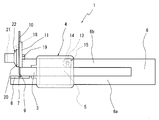
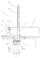
- FIG. 1 is a front view of the best first embodiment for carrying out the present invention.
- the present invention 1 can cut a board 2 such as styrene board or corrugated cardboard from the end into a strip-shaped member having a predetermined width.
- This board cutter 1 is a base that can be held with one hand in which a channel-shaped guide groove 3 that can be slid and moved by inserting the end of the board 2 into the side surface from one side.
- a body 4 and a substantially U-shaped cutter blade support 6 that is slidably attached to the base body 4 in a through hole 5 in a direction orthogonal to the guide groove 3 of the base body 4 and straddles the guide groove 3.
- a cutter blade insertion groove 7 attached to the tip of the lower member 6a of the cutter blade support 6 so that the upper surface is substantially flush with the lower surface 3a of the guide groove 3.
- the tip portion is inserted into the cutter blade insertion groove 7 of the cutter blade support base 8 at the tip portion of the blade support base 8 and the upper member 6b of the cutter blade support tool 6 and is parallel to the guide groove 3
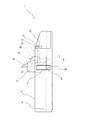
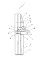
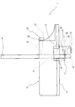
- the cutter blade support 6 is fixed to the base body 4 at an arbitrary position protruding from the bottom surface of the guide groove 3, and is screwed into a screw hole 12 formed in the base body 4.
- the cutter blade 10 is supported by a cutter blade insertion recess 18 in which an upper portion of the cutter blade 10 formed on the cutter blade support piece 11 protrudes outward, and is screwed with a bolt 19 fixed to the cutter blade support piece 11.
- a flange portion 20 for pressing and fixing the cutter blade 10 to be pressed is formed, and is attached so as to be detachable by a tightening nut 22 in which a groove 21 that can be rotated by a screwdriver or a coin is formed at the tip portion.
- the board cutter 1 having the above structure is inserted so that the end of the board 2 such as a styrene board or cardboard is in contact with the bottom surface of the guide groove 3, and the board 2 or the board 2 is kept in this state.
- the cutter 1 When the cutter 1 is slid and moved, it can be cut into a band shape having a width corresponding to the dimension between the bottom surface of the guide groove 3 and the cutter blade 10.
- the scale 16 of the cutter blade support 6 is aligned with the required position, and the cutter blade support 6 is used as a base with the tightening bolts 14 of the cutter blade support fixture 15. By fixing to the body 4, it can be set easily.
- FIG. 8 the board cutter 1 having the above structure is inserted so that the end of the board 2 such as a styrene board or cardboard is in contact with the bottom surface of the guide groove 3, and the board 2 or the board 2 is kept in this state.
- FIGS. 11 to 16 different modes for carrying out the present invention shown in FIGS. 11 to 16 will be described.
- the same components as those in the best mode for carrying out the present invention are designated by the same reference numerals and redundant description is omitted. To do.
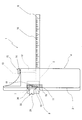
- the second embodiment for carrying out the present invention shown in FIGS. 11 to 13 is mainly different from the best first embodiment for carrying out the present invention in that a cutter blade is placed in the cutter blade insertion recess 18. 10 and a cutter blade support piece in which a cutter blade removal recess 23 is formed so that the cutter blade 10 can be easily removed by inserting a screwdriver or the like between the upper portion of the cutter blade 10 and the cutter blade insertion recess 18 from above.
- 11A is used, the board cutter 1A configured as described above can achieve the same effects as the first preferred embodiment for carrying out the present invention, and the upper portion of the cutter blade 10 can be It is possible to improve the safety by preventing the protrusion.
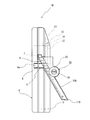
- the third embodiment for carrying out the present invention shown in FIGS. 14 to 16 is mainly different from the best first embodiment for carrying out the present invention in that the upper member 6b of the cutter blade support 6 is the same.
- the cutter blade support piece 11B in which the cutter blade insertion recess 18A capable of supporting the cutter blade 10A of the broken blade used in the cutter knife is used at the tip of the blade is used as the board cutter 1B thus configured.
- the same effects as those of the first embodiment for carrying out the present invention can be obtained, and the cutter blade 10A can be used while being folded, and can be used for a long time.
- the cutter blade support base 8 in which the cutter blade insertion groove 7 is formed has been described.
- the present invention is not limited to this, and the tip of the cutter blade 10 is applied. You may use the cutter blade support stand made from the synthetic resin material which touches.
- the present invention is used in an industry for manufacturing a board cutter for cutting a board such as a styrene board or a cardboard from the end with a constant width dimension.
Landscapes
- Life Sciences & Earth Sciences (AREA)
- Forests & Forestry (AREA)
- Engineering & Computer Science (AREA)
- Mechanical Engineering (AREA)
- Knives (AREA)
Abstract
L'invention concerne un dispositif de coupe pour carton. Le dispositif de coupe pour carton comporte : un élément de base, ayant formée sur une surface latérale de celui-ci une rainure de guidage similaire à un profilé dans laquelle l'extrémité d'un carton est insérée depuis la surface latérale et dans laquelle le carton peut coulisser, et qui peut être tenu d'une main ; un outil de support de lame de dispositif de coupe qui est attaché à l'élément de base de telle sorte que l'outil peut coulisser dans une direction perpendiculaire à la rainure de guidage de l'élément de base, qui croise la rainure de guidage, et qui a essentiellement la forme d’un C renversé ; une base de support de lame de dispositif de coupe attachée à l'extrémité avant d'un élément inférieur de l'outil de support de lame de dispositif de coupe de telle sorte que la surface supérieure de la base et la surface inférieure de la rainure de guidage sont essentiellement la même surface ; une lame de dispositif de coupe attachée à l'extrémité avant d'un élément supérieur de l'outil de support de lame de dispositif de coupe de telle sorte que l'extrémité avant est positionnée sur la base de support de lame de dispositif de coupe et la lame peut être détachée dans un état dans lequel la lame est parallèle à la rainure de guidage ; et un moyen de fixation de l'outil de support de lame de dispositif de coupe à des fins de fixation de l'outil de support de lame de dispositif de coupe sur l'élément de base en une position donnée au niveau de laquelle la lame de dispositif de coupe attachée à l'outil de support de lame de dispositif de coupe est en saillie par rapport à la surface de fond de la rainure de guidage. Le dispositif de coupe pour carton permet à une personne non formée de couper parfaitement le carton en morceaux ayant une dimension de largeur fixe par le biais d'un procédé simple. Dans le dispositif de coupe pour carton, il est possible de changer facilement une lame émoussée de dispositif de coupe.
Priority Applications (1)
| Application Number | Priority Date | Filing Date | Title |
|---|---|---|---|
| PCT/JP2008/059769 WO2009144786A1 (fr) | 2008-05-28 | 2008-05-28 | Dispositif de coupe pour carton |
Applications Claiming Priority (1)
| Application Number | Priority Date | Filing Date | Title |
|---|---|---|---|
| PCT/JP2008/059769 WO2009144786A1 (fr) | 2008-05-28 | 2008-05-28 | Dispositif de coupe pour carton |
Publications (1)
| Publication Number | Publication Date |
|---|---|
| WO2009144786A1 true WO2009144786A1 (fr) | 2009-12-03 |
Family
ID=41376686
Family Applications (1)
| Application Number | Title | Priority Date | Filing Date |
|---|---|---|---|
| PCT/JP2008/059769 Ceased WO2009144786A1 (fr) | 2008-05-28 | 2008-05-28 | Dispositif de coupe pour carton |
Country Status (1)
| Country | Link |
|---|---|
| WO (1) | WO2009144786A1 (fr) |
Cited By (1)
| Publication number | Priority date | Publication date | Assignee | Title |
|---|---|---|---|---|
| CN102896652A (zh) * | 2012-09-18 | 2013-01-30 | 樊荣 | 一种切菜机 |
Citations (3)
| Publication number | Priority date | Publication date | Assignee | Title |
|---|---|---|---|---|
| JPH0347796U (fr) * | 1989-09-13 | 1991-05-07 | ||
| JPH0518473U (ja) * | 1991-08-21 | 1993-03-09 | ミサワホーム株式会社 | 板状体の表面材カツター装置 |
| JP2001150383A (ja) * | 1999-11-25 | 2001-06-05 | Lion Office Products Corp | 紙裁断器 |
-
2008
- 2008-05-28 WO PCT/JP2008/059769 patent/WO2009144786A1/fr not_active Ceased
Patent Citations (3)
| Publication number | Priority date | Publication date | Assignee | Title |
|---|---|---|---|---|
| JPH0347796U (fr) * | 1989-09-13 | 1991-05-07 | ||
| JPH0518473U (ja) * | 1991-08-21 | 1993-03-09 | ミサワホーム株式会社 | 板状体の表面材カツター装置 |
| JP2001150383A (ja) * | 1999-11-25 | 2001-06-05 | Lion Office Products Corp | 紙裁断器 |
Cited By (1)
| Publication number | Priority date | Publication date | Assignee | Title |
|---|---|---|---|---|
| CN102896652A (zh) * | 2012-09-18 | 2013-01-30 | 樊荣 | 一种切菜机 |
Similar Documents
| Publication | Publication Date | Title |
|---|---|---|
| US12226843B2 (en) | Oscillating tool drywall blade | |
| US8272136B2 (en) | Wallboard cutting tool | |
| US20080295344A1 (en) | Utility knife blade | |
| KR100441924B1 (ko) | 다이 보드 및 그 제조 방법 | |
| CN201525008U (zh) | 用于电动工具上的导向装置 | |
| US20070163130A1 (en) | Cutting tee square | |
| CN210998988U (zh) | 一种epe板辅助切角架 | |
| US20050204887A1 (en) | Cutting guide | |
| TWI815491B (zh) | 圓鋸用導引裝置 | |
| JP7760361B2 (ja) | 長尺定規用位置決め装置 | |
| JP3180578U (ja) | 丸鋸用平行定規 | |
| US7107699B2 (en) | Workpiece size alignment device | |
| JP3694746B2 (ja) | 工作機械剛性簡易評価方法及び該方法に使用するテストピース | |
| CN212241416U (zh) | 一种用于形成切口的设备 | |
| CN201195216Y (zh) | 可更换多种锯片的锯子 | |
| JP5909342B2 (ja) | 丸鋸ガイド具 | |
| JP4234535B2 (ja) | 丸鋸用定規 | |
| KR102953009B1 (ko) | 절단 기능을 갖는 자 | |
| CN111168782B (zh) | 用于制造广泛的切口的方法和设备 | |
| JP2009220183A (ja) | 塗膜付着試験用切り込み線形成刃具および切り込み線形成方法 | |
| IES20060671A2 (en) | Cutting tool | |
| JP3073087U (ja) | 罫引き具 | |
| JP2005238730A (ja) | ボード切断具 | |
| JP4553659B2 (ja) | 溝切具 | |
| US20040172845A1 (en) | Rip guide tool |
Legal Events
| Date | Code | Title | Description |
|---|---|---|---|
| 121 | Ep: the epo has been informed by wipo that ep was designated in this application |
Ref document number: 08764785 Country of ref document: EP Kind code of ref document: A1 |
|
| NENP | Non-entry into the national phase |
Ref country code: DE |
|
| NENP | Non-entry into the national phase |
Ref country code: JP |
|
| 122 | Ep: pct application non-entry in european phase |
Ref document number: 08764785 Country of ref document: EP Kind code of ref document: A1 |