WO2009145103A1 - Objectif et dispositif de capture optique - Google Patents
Objectif et dispositif de capture optique Download PDFInfo
- Publication number
- WO2009145103A1 WO2009145103A1 PCT/JP2009/059341 JP2009059341W WO2009145103A1 WO 2009145103 A1 WO2009145103 A1 WO 2009145103A1 JP 2009059341 W JP2009059341 W JP 2009059341W WO 2009145103 A1 WO2009145103 A1 WO 2009145103A1
- Authority
- WO
- WIPO (PCT)
- Prior art keywords
- optical
- path difference
- optical path
- objective lens
- providing structure
- Prior art date
- Legal status (The legal status is an assumption and is not a legal conclusion. Google has not performed a legal analysis and makes no representation as to the accuracy of the status listed.)
- Ceased
Links
Images




Classifications
-
- G—PHYSICS
- G11—INFORMATION STORAGE
- G11B—INFORMATION STORAGE BASED ON RELATIVE MOVEMENT BETWEEN RECORD CARRIER AND TRANSDUCER
- G11B7/00—Recording or reproducing by optical means, e.g. recording using a thermal beam of optical radiation by modifying optical properties or the physical structure, reproducing using an optical beam at lower power by sensing optical properties; Record carriers therefor
- G11B7/12—Heads, e.g. forming of the optical beam spot or modulation of the optical beam
- G11B7/125—Optical beam sources therefor, e.g. laser control circuitry specially adapted for optical storage devices; Modulators, e.g. means for controlling the size or intensity of optical spots or optical traces
- G11B7/127—Lasers; Multiple laser arrays
- G11B7/1275—Two or more lasers having different wavelengths
-
- G—PHYSICS
- G02—OPTICS
- G02B—OPTICAL ELEMENTS, SYSTEMS OR APPARATUS
- G02B3/00—Simple or compound lenses
- G02B3/02—Simple or compound lenses with non-spherical faces
- G02B3/08—Simple or compound lenses with non-spherical faces with discontinuous faces, e.g. Fresnel lens
-
- G—PHYSICS
- G02—OPTICS
- G02B—OPTICAL ELEMENTS, SYSTEMS OR APPARATUS
- G02B5/00—Optical elements other than lenses
- G02B5/18—Diffraction gratings
- G02B5/1876—Diffractive Fresnel lenses; Zone plates; Kinoforms
-
- G—PHYSICS
- G11—INFORMATION STORAGE
- G11B—INFORMATION STORAGE BASED ON RELATIVE MOVEMENT BETWEEN RECORD CARRIER AND TRANSDUCER
- G11B7/00—Recording or reproducing by optical means, e.g. recording using a thermal beam of optical radiation by modifying optical properties or the physical structure, reproducing using an optical beam at lower power by sensing optical properties; Record carriers therefor
- G11B7/12—Heads, e.g. forming of the optical beam spot or modulation of the optical beam
- G11B7/135—Means for guiding the beam from the source to the record carrier or from the record carrier to the detector
- G11B7/1353—Diffractive elements, e.g. holograms or gratings
-
- G—PHYSICS
- G11—INFORMATION STORAGE
- G11B—INFORMATION STORAGE BASED ON RELATIVE MOVEMENT BETWEEN RECORD CARRIER AND TRANSDUCER
- G11B7/00—Recording or reproducing by optical means, e.g. recording using a thermal beam of optical radiation by modifying optical properties or the physical structure, reproducing using an optical beam at lower power by sensing optical properties; Record carriers therefor
- G11B7/12—Heads, e.g. forming of the optical beam spot or modulation of the optical beam
- G11B7/135—Means for guiding the beam from the source to the record carrier or from the record carrier to the detector
- G11B7/1365—Separate or integrated refractive elements, e.g. wave plates
- G11B7/1367—Stepped phase plates
-
- G—PHYSICS
- G11—INFORMATION STORAGE
- G11B—INFORMATION STORAGE BASED ON RELATIVE MOVEMENT BETWEEN RECORD CARRIER AND TRANSDUCER
- G11B7/00—Recording or reproducing by optical means, e.g. recording using a thermal beam of optical radiation by modifying optical properties or the physical structure, reproducing using an optical beam at lower power by sensing optical properties; Record carriers therefor
- G11B7/12—Heads, e.g. forming of the optical beam spot or modulation of the optical beam
- G11B7/135—Means for guiding the beam from the source to the record carrier or from the record carrier to the detector
- G11B7/1372—Lenses
- G11B7/1374—Objective lenses
-
- G—PHYSICS
- G11—INFORMATION STORAGE
- G11B—INFORMATION STORAGE BASED ON RELATIVE MOVEMENT BETWEEN RECORD CARRIER AND TRANSDUCER
- G11B7/00—Recording or reproducing by optical means, e.g. recording using a thermal beam of optical radiation by modifying optical properties or the physical structure, reproducing using an optical beam at lower power by sensing optical properties; Record carriers therefor
- G11B2007/0003—Recording, reproducing or erasing systems characterised by the structure or type of the carrier
- G11B2007/0006—Recording, reproducing or erasing systems characterised by the structure or type of the carrier adapted for scanning different types of carrier, e.g. CD & DVD
Definitions
- the optical system for high-density optical discs and the optical system for DVDs and CDs must be shared in compatible optical pickup devices. It is preferable to reduce the number of optical components constituting the optical pickup device as much as possible. And, it is most advantageous to simplify the configuration of the optical pickup device and to reduce the cost to make the objective lens arranged facing the optical disc in common.
- an optical path difference providing structure having wavelength dependency of spherical aberration is formed in the objective optical system. It is necessary to reduce the spherical aberration caused by the difference in wavelength and the thickness of the protective layer.
- the objective lens according to claim 5 is the objective lens according to any one of claims 1 to 4, wherein the first optical path difference providing structure passes through the first optical path difference providing structure.
- the first-order diffracted light amount of one light beam is made larger than any other order (including zero-order) diffracted light amount
- the -1st-order diffracted light amount of the second light beam that has passed through the first optical path difference providing structure Is larger than the diffracted light amount of any order (including the 0th order)
- the ⁇ 2nd order diffracted light amount of the third light flux that has passed through the first optical path difference providing structure is set to any other order (including the 0th order).
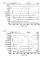
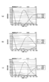
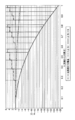
- the first optical path difference providing structure that is Comparative Example 2 shown in FIG. 11B has the diffraction characteristics shown in FIG. More specifically, the first-order diffracted light of the first wavelength has a peak value near 405 nm, the second-order diffracted light of the second wavelength has a peak value near 680 nm, and the -3rd-order diffracted light of the third wavelength has a peak value of 800 nm. It has a peak value at much higher wavelengths. Therefore, when a light beam having a wavelength of about 405 nm is used as the first light beam and a light beam having a wavelength of about 655 nm is used as the second light beam, a diffraction efficiency close to the peak value of the waveform can be obtained.
- the objective lens according to claim 8 is characterized in that, in the invention according to any one of claims 1 to 7, the amount of step between adjacent steps in the step unit is substantially equal.
- optical pickup device described in claim 14 is characterized in that, in the invention described in any one of claims 11 to 13, only the lowest step satisfies the expression (1).
- the first light source, the second light source, and the third light source may be unitized.
- the unitization means that the first light source and the second light source are fixedly housed in one package, for example. However, the unitization is not limited to this, and the two light sources are fixed so that the aberration cannot be corrected. Is widely included.
- a light receiving element to be described later may be packaged.
- the objective lens refers to an optical system that is disposed at a position facing the optical disk in the optical pickup device and has a function of condensing the light beam emitted from the light source onto the information recording surface of the optical disk.
- the objective lens is an optical system which is disposed at a position facing the optical disk in the optical pickup device and has a function of condensing a light beam emitted from the light source on the information recording surface of the optical disk, and further includes an actuator An optical system that can be integrally displaced at least in the optical axis direction.
- the objective lens is preferably a single objective lens, but may be formed of a plurality of optical elements.
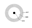
- the flare may be a spot peripheral portion around the spot center portion where the light density is high and there is no spot middle portion, and the light spot density is lower than the spot center portion.
- the periphery of the spot is called flare.
- the third light flux that has passed through the second optical path difference providing structure provided in the peripheral region of the objective lens may form such a spot peripheral portion on the information recording surface of the third optical disc.
- the diffraction efficiency for each wavelength in the central region can be set as appropriate according to the application of the optical pickup device.
- the diffraction efficiency of the central region and / or the peripheral region is expressed as It is preferable to set with emphasis.
- the second and third light fluxes are emphasized with respect to the diffraction efficiency of the central region. It is preferable to set the diffraction efficiency of the peripheral region with the second light flux as important.
- ⁇ represents the effective diameter of the objective lens when the first optical disk is used.
- An optical information recording / reproducing apparatus includes an optical disc drive apparatus having the above-described optical pickup apparatus.
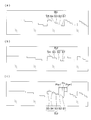
- the third optical path difference providing structure makes the third-order diffracted light amount of the first light beam that has passed through larger than any other order diffracted light amount. Note that the ratios of the areas of the central region, the peripheral region, and the outermost peripheral region in FIGS. 5A and 5B are not accurately represented.
- Polarized light is converted by the / 4 wavelength plate and enters the objective lens OBJ.
- the light beam condensed by the central region and the peripheral region of the objective lens OBJ (the light beam that has passed through the most peripheral region is flared and forms a spot peripheral part) is passed through the protective substrate PL2 having a thickness of 0.6 mm.
- the spot is formed on the information recording surface RL2 of the DVD, and the center of the spot is formed.
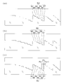
- the ⁇ 1st order diffracted light of the second light beam generated in the central region and the ⁇ 1st order diffracted light of the second light beam generated in the peripheral region are collected on the information recording surface of the DVD.
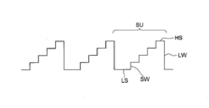
- the pitch of the diffractive structure is determined by an integer part of the optical path difference function of Formula 2, and the optical path length given to the light flux of each wavelength for each ring zone is expressed by the function of Formula 3 in the table. It is defined by a mathematical formula into which the coefficient shown is substituted.
Landscapes
- Physics & Mathematics (AREA)
- Optics & Photonics (AREA)
- General Physics & Mathematics (AREA)
- Optical Head (AREA)
- Optical Recording Or Reproduction (AREA)
- Lenses (AREA)
- Diffracting Gratings Or Hologram Optical Elements (AREA)
Abstract
Priority Applications (3)
| Application Number | Priority Date | Filing Date | Title |
|---|---|---|---|
| US12/994,446 US8385181B2 (en) | 2008-05-27 | 2009-05-21 | Objective lens and optical pickup apparatus |
| CN2009801188513A CN102037512B (zh) | 2008-05-27 | 2009-05-21 | 物镜及光拾取装置 |
| JP2009546544A JP4502079B2 (ja) | 2008-05-27 | 2009-05-21 | 対物レンズ及び光ピックアップ装置 |
Applications Claiming Priority (2)
| Application Number | Priority Date | Filing Date | Title |
|---|---|---|---|
| JP2008138021 | 2008-05-27 | ||
| JP2008-138021 | 2008-05-27 |
Publications (1)
| Publication Number | Publication Date |
|---|---|
| WO2009145103A1 true WO2009145103A1 (fr) | 2009-12-03 |
Family
ID=41376981
Family Applications (1)
| Application Number | Title | Priority Date | Filing Date |
|---|---|---|---|
| PCT/JP2009/059341 Ceased WO2009145103A1 (fr) | 2008-05-27 | 2009-05-21 | Objectif et dispositif de capture optique |
Country Status (4)
| Country | Link |
|---|---|
| US (1) | US8385181B2 (fr) |
| JP (2) | JP4502079B2 (fr) |
| CN (1) | CN102037512B (fr) |
| WO (1) | WO2009145103A1 (fr) |
Cited By (2)
| Publication number | Priority date | Publication date | Assignee | Title |
|---|---|---|---|---|
| WO2012111554A1 (fr) * | 2011-02-17 | 2012-08-23 | コニカミノルタオプト株式会社 | Lentille d'objectif et dispositif de lecture optique |
| JP2012189966A (ja) * | 2011-03-14 | 2012-10-04 | Kansai Univ | 集光フィルム及び太陽電池モジュール |
Families Citing this family (5)
| Publication number | Priority date | Publication date | Assignee | Title |
|---|---|---|---|---|
| WO2011122090A1 (fr) * | 2010-03-30 | 2011-10-06 | コニカミノルタオプト株式会社 | Moule, élément optique et procédé de fabrication d'un élément optique |
| KR20140106055A (ko) * | 2013-02-25 | 2014-09-03 | 도시바삼성스토리지테크놀러지코리아 주식회사 | 광픽업 및 이를 채용한 광정보저장매체 시스템 |
| TWI772387B (zh) * | 2017-03-17 | 2022-08-01 | 日商大日本印刷股份有限公司 | 繞射光學元件 |
| JP7196406B2 (ja) * | 2017-03-17 | 2022-12-27 | 大日本印刷株式会社 | 回折光学素子 |
| JP2019086296A (ja) * | 2017-11-01 | 2019-06-06 | 株式会社ミツトヨ | 光学式エンコーダおよびこれを備えた測定器 |
Citations (2)
| Publication number | Priority date | Publication date | Assignee | Title |
|---|---|---|---|---|
| JP2005141800A (ja) * | 2003-11-04 | 2005-06-02 | Konica Minolta Opto Inc | 発散角変換素子及び光ピックアップ装置 |
| JP2007294101A (ja) * | 2004-04-12 | 2007-11-08 | Konica Minolta Opto Inc | 対物レンズ |
Family Cites Families (7)
| Publication number | Priority date | Publication date | Assignee | Title |
|---|---|---|---|---|
| US6515955B2 (en) * | 2000-04-14 | 2003-02-04 | Pentax Corporation | Objective optical system for optical pick-up |
| TWI239520B (en) * | 2001-10-12 | 2005-09-11 | Konica Corp | Objective lens, optical element, optical pick-up apparatus and optical information recording and/or reproducing apparatus equipped therewith |
| JP5002118B2 (ja) * | 2003-06-18 | 2012-08-15 | コニカミノルタアドバンストレイヤー株式会社 | 光ピックアップ装置用の光学素子、及び光ピックアップ装置 |
| JP4677275B2 (ja) | 2005-04-27 | 2011-04-27 | Towa株式会社 | 電子部品用のエキスパンド装置 |
| CN101034570A (zh) * | 2006-03-07 | 2007-09-12 | 柯尼卡美能达精密光学株式会社 | 光拾取装置、对物光学元件和光信息记录重放装置 |
| TWI394152B (zh) * | 2007-07-30 | 2013-04-21 | Sony Corp | Objective lens, optical read / write head and optical disc device |
| JP4775422B2 (ja) * | 2008-08-28 | 2011-09-21 | ソニー株式会社 | 集光光学デバイス、光ピックアップ及び光ディスク装置 |
-
2009
- 2009-05-21 WO PCT/JP2009/059341 patent/WO2009145103A1/fr not_active Ceased
- 2009-05-21 CN CN2009801188513A patent/CN102037512B/zh not_active Expired - Fee Related
- 2009-05-21 US US12/994,446 patent/US8385181B2/en not_active Expired - Fee Related
- 2009-05-21 JP JP2009546544A patent/JP4502079B2/ja not_active Expired - Fee Related
- 2009-11-26 JP JP2009268563A patent/JP2010044861A/ja active Pending
Patent Citations (2)
| Publication number | Priority date | Publication date | Assignee | Title |
|---|---|---|---|---|
| JP2005141800A (ja) * | 2003-11-04 | 2005-06-02 | Konica Minolta Opto Inc | 発散角変換素子及び光ピックアップ装置 |
| JP2007294101A (ja) * | 2004-04-12 | 2007-11-08 | Konica Minolta Opto Inc | 対物レンズ |
Cited By (2)
| Publication number | Priority date | Publication date | Assignee | Title |
|---|---|---|---|---|
| WO2012111554A1 (fr) * | 2011-02-17 | 2012-08-23 | コニカミノルタオプト株式会社 | Lentille d'objectif et dispositif de lecture optique |
| JP2012189966A (ja) * | 2011-03-14 | 2012-10-04 | Kansai Univ | 集光フィルム及び太陽電池モジュール |
Also Published As
| Publication number | Publication date |
|---|---|
| JP2010044861A (ja) | 2010-02-25 |
| JP4502079B2 (ja) | 2010-07-14 |
| CN102037512B (zh) | 2012-08-29 |
| US20110075546A1 (en) | 2011-03-31 |
| JPWO2009145103A1 (ja) | 2011-10-13 |
| US8385181B2 (en) | 2013-02-26 |
| CN102037512A (zh) | 2011-04-27 |
Similar Documents
| Publication | Publication Date | Title |
|---|---|---|
| JP5136810B2 (ja) | 光ピックアップ装置 | |
| WO2010013616A1 (fr) | Lentille d'objectif et dispositif optique de capture | |
| JP4502079B2 (ja) | 対物レンズ及び光ピックアップ装置 | |
| JPWO2007145202A1 (ja) | 光学素子の設計方法、光学素子及び光ピックアップ装置 | |
| JPWO2009154072A1 (ja) | 対物レンズ、光ピックアップ装置及び光ディスクドライブ装置 | |
| JP2008293630A (ja) | 光ピックアップ装置及び対物光学素子 | |
| JPWO2009116385A1 (ja) | 対物レンズ及び光ピックアップ装置 | |
| JP4453785B2 (ja) | 光ピックアップ装置用の対物レンズ及び光ピックアップ装置 | |
| JPWO2007123112A1 (ja) | 光ピックアップ装置、光学素子及び光情報記録再生装置並びに光学素子の設計方法 | |
| WO2009128445A1 (fr) | Lentille de focalisation et dispositif de détection optique | |
| JP2009110591A (ja) | 対物レンズ及び光ピックアップ装置 | |
| JP2007128654A (ja) | 多焦点対物レンズ、光ピックアップ装置及び光情報記録再生装置 | |
| JP2010055683A (ja) | 対物光学素子及び光ピックアップ装置 | |
| JP4385902B2 (ja) | 対物光学素子及び光ピックアップ装置 | |
| JP2010153006A (ja) | 対物光学素子及び光ピックアップ装置 | |
| JP2010055732A (ja) | 対物光学素子及び光ピックアップ装置 | |
| JPWO2010089933A1 (ja) | 対物レンズ及び光ピックアップ装置 | |
| JP5408549B2 (ja) | 光ピックアップ装置用の対物レンズ及び光ピックアップ装置 | |
| JPWO2009147942A1 (ja) | 対物レンズ及び光ピックアップ装置 | |
| JPWO2011114895A1 (ja) | 対物レンズ、光ピックアップ装置及び光情報記録再生装置 | |
| JPWO2009051019A1 (ja) | 光ピックアップ装置、光ピックアップ装置用の対物光学素子及び光情報記録再生装置 | |
| JPWO2010067733A1 (ja) | 対物レンズ及び光ピックアップ装置 | |
| WO2011148832A1 (fr) | Objectif pour tête optique, tête optique et dispositif de lecture et d'écriture d'informations optiques | |
| JP2011248936A (ja) | 光ピックアップ装置用の対物レンズ、光ピックアップ装置及び光情報記録再生装置 | |
| JPWO2011040225A1 (ja) | 回折素子及び光ピックアップ装置 |
Legal Events
| Date | Code | Title | Description |
|---|---|---|---|
| WWE | Wipo information: entry into national phase |
Ref document number: 200980118851.3 Country of ref document: CN |
|
| WWE | Wipo information: entry into national phase |
Ref document number: 2009546544 Country of ref document: JP |
|
| 121 | Ep: the epo has been informed by wipo that ep was designated in this application |
Ref document number: 09754611 Country of ref document: EP Kind code of ref document: A1 |
|
| WWE | Wipo information: entry into national phase |
Ref document number: 12994446 Country of ref document: US |
|
| NENP | Non-entry into the national phase |
Ref country code: DE |
|
| 122 | Ep: pct application non-entry in european phase |
Ref document number: 09754611 Country of ref document: EP Kind code of ref document: A1 |