WO2009147892A1 - 折り畳み式シート - Google Patents
折り畳み式シート Download PDFInfo
- Publication number
- WO2009147892A1 WO2009147892A1 PCT/JP2009/056278 JP2009056278W WO2009147892A1 WO 2009147892 A1 WO2009147892 A1 WO 2009147892A1 JP 2009056278 W JP2009056278 W JP 2009056278W WO 2009147892 A1 WO2009147892 A1 WO 2009147892A1
- Authority
- WO
- WIPO (PCT)
- Prior art keywords
- seat
- support bracket
- main body
- frame
- vehicle
- Prior art date
- Legal status (The legal status is an assumption and is not a legal conclusion. Google has not performed a legal analysis and makes no representation as to the accuracy of the status listed.)
- Ceased
Links
Images


Classifications
-
- B—PERFORMING OPERATIONS; TRANSPORTING
- B60—VEHICLES IN GENERAL
- B60N—SEATS SPECIALLY ADAPTED FOR VEHICLES; VEHICLE PASSENGER ACCOMMODATION NOT OTHERWISE PROVIDED FOR
- B60N2/00—Seats specially adapted for vehicles; Arrangement or mounting of seats in vehicles
- B60N2/24—Seats specially adapted for vehicles; Arrangement or mounting of seats in vehicles for particular purposes or particular vehicles
- B60N2/30—Non-dismountable or dismountable seats storable in a non-use position, e.g. foldable spare seats
- B60N2/3002—Non-dismountable or dismountable seats storable in a non-use position, e.g. foldable spare seats back-rest movements
- B60N2/3004—Non-dismountable or dismountable seats storable in a non-use position, e.g. foldable spare seats back-rest movements by rotation only
- B60N2/3009—Non-dismountable or dismountable seats storable in a non-use position, e.g. foldable spare seats back-rest movements by rotation only about transversal axis
- B60N2/3011—Non-dismountable or dismountable seats storable in a non-use position, e.g. foldable spare seats back-rest movements by rotation only about transversal axis the back-rest being hinged on the cushion, e.g. "portefeuille movement"
-
- B—PERFORMING OPERATIONS; TRANSPORTING
- B60—VEHICLES IN GENERAL
- B60N—SEATS SPECIALLY ADAPTED FOR VEHICLES; VEHICLE PASSENGER ACCOMMODATION NOT OTHERWISE PROVIDED FOR
- B60N2/00—Seats specially adapted for vehicles; Arrangement or mounting of seats in vehicles
- B60N2/02—Seats specially adapted for vehicles; Arrangement or mounting of seats in vehicles the seat or part thereof being movable, e.g. adjustable
- B60N2/20—Seats specially adapted for vehicles; Arrangement or mounting of seats in vehicles the seat or part thereof being movable, e.g. adjustable the back-rest being tiltable, e.g. to permit easy access
-
- B—PERFORMING OPERATIONS; TRANSPORTING
- B60—VEHICLES IN GENERAL
- B60N—SEATS SPECIALLY ADAPTED FOR VEHICLES; VEHICLE PASSENGER ACCOMMODATION NOT OTHERWISE PROVIDED FOR
- B60N2/00—Seats specially adapted for vehicles; Arrangement or mounting of seats in vehicles
- B60N2/24—Seats specially adapted for vehicles; Arrangement or mounting of seats in vehicles for particular purposes or particular vehicles
- B60N2/30—Non-dismountable or dismountable seats storable in a non-use position, e.g. foldable spare seats
- B60N2/3038—Cushion movements
- B60N2/304—Cushion movements by rotation only
- B60N2/3045—Cushion movements by rotation only about transversal axis
- B60N2/305—Cushion movements by rotation only about transversal axis the cushion being hinged on the vehicle frame
-
- B—PERFORMING OPERATIONS; TRANSPORTING
- B60—VEHICLES IN GENERAL
- B60N—SEATS SPECIALLY ADAPTED FOR VEHICLES; VEHICLE PASSENGER ACCOMMODATION NOT OTHERWISE PROVIDED FOR
- B60N2/00—Seats specially adapted for vehicles; Arrangement or mounting of seats in vehicles
- B60N2/24—Seats specially adapted for vehicles; Arrangement or mounting of seats in vehicles for particular purposes or particular vehicles
- B60N2/42—Seats specially adapted for vehicles; Arrangement or mounting of seats in vehicles for particular purposes or particular vehicles the seat constructed to protect the occupant from the effect of abnormal g-forces, e.g. crash or safety seats
- B60N2/4207—Seats specially adapted for vehicles; Arrangement or mounting of seats in vehicles for particular purposes or particular vehicles the seat constructed to protect the occupant from the effect of abnormal g-forces, e.g. crash or safety seats characterised by the direction of the g-forces
- B60N2/4214—Seats specially adapted for vehicles; Arrangement or mounting of seats in vehicles for particular purposes or particular vehicles the seat constructed to protect the occupant from the effect of abnormal g-forces, e.g. crash or safety seats characterised by the direction of the g-forces longitudinal
-
- B—PERFORMING OPERATIONS; TRANSPORTING
- B60—VEHICLES IN GENERAL
- B60N—SEATS SPECIALLY ADAPTED FOR VEHICLES; VEHICLE PASSENGER ACCOMMODATION NOT OTHERWISE PROVIDED FOR
- B60N2/00—Seats specially adapted for vehicles; Arrangement or mounting of seats in vehicles
- B60N2/24—Seats specially adapted for vehicles; Arrangement or mounting of seats in vehicles for particular purposes or particular vehicles
- B60N2/42—Seats specially adapted for vehicles; Arrangement or mounting of seats in vehicles for particular purposes or particular vehicles the seat constructed to protect the occupant from the effect of abnormal g-forces, e.g. crash or safety seats
- B60N2/427—Seats or parts thereof displaced during a crash
- B60N2/42709—Seats or parts thereof displaced during a crash involving residual deformation or fracture of the structure
-
- B—PERFORMING OPERATIONS; TRANSPORTING
- B60—VEHICLES IN GENERAL
- B60N—SEATS SPECIALLY ADAPTED FOR VEHICLES; VEHICLE PASSENGER ACCOMMODATION NOT OTHERWISE PROVIDED FOR
- B60N2/00—Seats specially adapted for vehicles; Arrangement or mounting of seats in vehicles
- B60N2/24—Seats specially adapted for vehicles; Arrangement or mounting of seats in vehicles for particular purposes or particular vehicles
- B60N2/42—Seats specially adapted for vehicles; Arrangement or mounting of seats in vehicles for particular purposes or particular vehicles the seat constructed to protect the occupant from the effect of abnormal g-forces, e.g. crash or safety seats
- B60N2/427—Seats or parts thereof displaced during a crash
- B60N2/42727—Seats or parts thereof displaced during a crash involving substantially rigid displacement
- B60N2/42745—Seats or parts thereof displaced during a crash involving substantially rigid displacement of the back-rest
Definitions
- the present invention relates to a foldable sheet.
- the fragile portion is an inclined portion bent in a triangular cross section, and absorbs impact energy by bending and deforming the inclined portion when a load is input to the seat from the front or rear of the vehicle. It is configured.
- the inclined portion is arranged at the front end of the side frame that is in the vicinity of the surface of the seat back. Therefore, when the occupant is seated on the seat, the inclined portion protrudes toward the occupant, and there is a problem that the occupant feels uncomfortable and the seating comfort is lowered.
- the present invention was invented in view of the above-described conventional problems, and an object of the present invention is to provide a foldable seat that can maintain excellent sitting comfort without feeling uncomfortable when an occupant is seated. Is.
- a seat frame in which a seat back frame is rotatably attached to a seat cushion frame, and a main body part fixed to the seat cushion frame and constituting a reclining mechanism part
- a main body part supporting bracket, and a driven part supporting bracket which is fixed to the seat cushion frame and supports the driven part constituting the reclining mechanism part, and the main body part supporting bracket and the driven part.
- the support bracket is disposed at a predetermined interval from the outer surface of the seat cushion and the seat back toward the inward side, and at least one of the main body support bracket and the follower support bracket is disposed in the vehicle longitudinal direction. From the load input to the seat frame The impact absorbing portion to absorb the impact energy is provided.
- the main body support bracket and the follower support bracket are arranged at predetermined intervals from the outer surface of the seat cushion and the seat back toward the inward side, and the main body An impact absorbing portion is formed on the part supporting bracket and / or the follower supporting bracket. Therefore, when the occupant is seated on the seat, the occupant does not feel uncomfortable by the impact absorbing portion, so that it is possible to maintain excellent sitting comfort. Further, when the load is input to the seat, the impact absorbing portion is deformed and absorbs the impact energy at a position spaced from the occupant, so that the impact energy absorption efficiency is improved.
- FIG. 1 is a perspective view of a seat frame constituting a foldable seat according to the first embodiment.
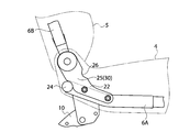
- FIG. 2 is a side view of FIG.
- FIG. 3 is a sectional view taken along line XX of FIG.
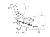
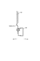
- FIG. 4 is an enlarged side view of a main part of a portion to which a follower support bracket for supporting the follower constituting the reclining mechanism of FIG. 1 is attached.
- FIG. 5 is a cross-sectional view showing a state in which the main body support bracket is deformed in the vehicle rearward direction and absorbs impact energy by a load input to the seat frame from the front of the vehicle.
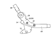
- FIG. 6 is a side view showing a state in which the follower support bracket is deformed in the vehicle rearward direction and absorbs impact energy by a load input to the seat frame from the front of the vehicle.
- FIG. 7 is a cross-sectional view showing the vicinity of the main body support bracket according to the second embodiment, and corresponds to FIG. 3 in the first embodiment.
- FIG. 8 is a side view showing the vicinity of the follower supporting bracket according to the second embodiment, and corresponds to FIG. 4 in the first embodiment.
- FIG. 9 is a cross-sectional view taken along line YY of FIG.
- FIG. 1 is a perspective view of a seat frame constituting a foldable seat according to the first embodiment
- FIG. 2 is a side view of FIG. 1
- FIG. 3 is a sectional view taken along line XX of FIG. 1
- FIG. 5 is an enlarged side view of a main part of a portion where a follower support bracket for supporting a follower constituting the reclining mechanism is attached.
- FIG. FIG. 6 is a side view showing a state in which the follower support bracket is deformed in the vehicle rearward direction and absorbs impact energy by a load input to the seat frame from the front of the vehicle.
- the seat cushion and the seat back are omitted, and only the seat frame is shown.
- the arrow FR indicates the front of the vehicle
- the arrow RR indicates the rear of the vehicle
- the arrow X indicates the vehicle width direction
- the arrow Z indicates the vehicle height direction.
- the folding seat 1 of this embodiment is a three-seater rear seat, and has a structure in which a one-person folding seat 2 and a two-person folding seat 3 are connected.
- both sheets have basically the same configuration, the present invention will be described by taking a folding seat 3 for two persons as an example.
- the two-person foldable seat 3 is attached to the seat frame 6 to which the seat cushion 4 and the seat back 5 are attached, to the vehicle front side of the seat frame 6, and fixed to the vehicle floor 7.
- a front leg 8 a rear frame 10 attached to the rear of the seat frame 6 so as to be pivotable, and detachable from a striker 9 fixed to the vehicle floor 7, and a seat cushion 4.
- a reclining mechanism unit 11 that can fold the seat back 5 freely.
- the seat frame 6 is connected by combining a plurality of steel pipes, and includes a seat cushion frame 6A for attaching the seat cushion 4 and a seat back frame 6B for attaching the seat back 5.
- the seat back frame 6B operates the strap 12 (see FIG. 1) that protrudes outward from the upper end of the seat back 5 connected to the reclining mechanism portion 11 described later, so that the seat back frame 6B It is configured to be rotatable (foldable) in the direction.
- the front leg portion 8 is a floor side leg portion 8A fixed to the vehicle floor 7, and a frame fixed to the seat cushion frame 6A so as to be rotatable about the rotation shaft 13 with respect to the floor side leg portion 8A. It consists of side legs 8B.
- the front leg 8 is provided in a pair of left and right at a predetermined interval in the vehicle width direction.
- the rear leg 10 has a locking device (not shown) that can be freely engaged with and disengaged from the striker 9, and the engagement with the striker 9 can be released by pulling the strap belt 14. It is configured.
- the rear leg 10 has a pivot fulcrum shaft 15 provided on the tip side attached to the bracket 16 of the seat cushion frame 6A so as to be rotatable. In the present embodiment, two rear leg portions 10 are provided at predetermined intervals in the vehicle width direction.
- the reclining mechanism unit 11 includes a main body part 17 attached to the center part in the vehicle width direction of the seat back frame 6B, and a driven part 19 connected to the main body part 17 by a rod 18 and attached to the side part of the seat back frame 6B. It consists of.
- a lock release mechanism unit 20 is connected to the main body unit 17.
- the unlocking mechanism 20 is connected to the strap 12 that releases the locked state of the seat back frame 6B with respect to the seat cushion frame 6A.
- the seat cushion frame 6A is provided with a main body support bracket 21 that supports the main body 17 of the reclining mechanism 11 and a follower support bracket 22 that supports the follower 19.
- the main body support bracket 21 includes a fixing portion 21A fixed to the seat cushion frame 6A by fastening means such as bolts and nuts, and a connecting portion 21B rising vertically from the fixing portion 21A. It is formed in a substantially L shape when viewed from the front.
- the connecting portion 21 ⁇ / b> B is bent in an approximately L shape as a whole in a side view. Specifically, the rear portion is bent upward with respect to the front portion with the central portion in the front-rear direction as a boundary.
- the bent portion 23 of the main body support bracket 21 is the shock absorbing portion 30.
- the main body support bracket 21 is disposed at a predetermined distance from the outer surfaces of the seat cushion 4 and the seat back 5 inward (downward and rearward). . That is, the vehicle front end edge of the connecting portion 21 ⁇ / b> B of the main body supporting bracket 21 is disposed at a position spaced apart from the outer surfaces of the seat cushion 4 and the seat back 5 downward and rearward. Therefore, when the occupant is seated on the seat, the main body support bracket 21 is disposed at a position separated from the occupant's body, and therefore, the occupant does not feel uncomfortable with the main body support bracket 21.
- the impact absorbing portion 30 is deformed so that the main body supporting bracket 21 is bent toward the rear of the vehicle with a main pipe 24 extending in the vehicle width direction at the rear end portion of the seat cushion frame 6A. It is designed to absorb impact energy. Specifically, as shown in FIG. 5, the bent portion 23 of the main body support bracket 21 opens to the vehicle rear side with the main pipe 24 as a fulcrum, for example, by a load input to the seat frame 6 from the front of the vehicle. The impact energy is absorbed by a deformation that extends (in particular, plastic deformation). Therefore, the main body support bracket 21 is not deformed in the vehicle width direction as in the prior art, but is deformed rearward of the vehicle.
- the follower supporting bracket 22 is fixed to the side surface of the seat cushion frame 6A by fastening means such as bolts and nuts as shown in FIGS.
- the follower support bracket 22 is formed as a substantially L-shaped flat plate when viewed from the side, and is fixed to the side surface of the seat cushion frame with the plate thickness direction as the mounting direction.
- the bent portion 25 absorbs impact energy by extending and deforming so as to open in the vehicle front-rear direction with the load input to the seat frame 6 from the vehicle front-rear direction. Is set in the shock absorber 30.
- the load when a load is input to the seat frame 6 from the front-rear direction of the vehicle, the load is transmitted to the L-shaped follower support bracket 22, and the bent portion 25 extends so as to open in the front-rear direction of the vehicle.
- the impact energy is absorbed by (especially plastic deformation).
- the bent portion 25 which is the shock absorbing portion 30 bends the follower support bracket 22 toward the vehicle rear, with the main pipe 24 provided in the vehicle width direction behind the seat cushion frame 6A in the vehicle width direction. It is designed to absorb impact energy. Specifically, as shown in FIG. 6, for example, due to a load input to the seat frame 6 from the front of the vehicle, the bent portion 25 of the follower support bracket 22 extends to the rear of the vehicle with the main pipe 24 as a fulcrum. To absorb. Therefore, the follower support bracket 22 is not deformed in the vehicle width direction as in the prior art, but is deformed rearward of the vehicle, like the main body support bracket 21.
- the follower support bracket 22 is disposed at a predetermined distance from the outer surfaces of the seat cushion 4 and the seat back 5 inward (downward and rearward). . That is, the follower support bracket 22 is disposed at a position spaced apart from the outer surfaces of the seat cushion 4 and the seat back 5 downward and rearward. Accordingly, since the follower support bracket 22 is disposed away from the occupant's body while the occupant is seated on the seat, the occupant does not feel uncomfortable with the follower support bracket 22.
- the follower support bracket 22 is formed with a notch 26 that promotes deformation of the bent portion 25 that becomes the impact absorbing portion 30.
- the cutout 26 is cut out in an arc shape in a side view toward the main pipe 24.
- the notch 26 may be formed in the vicinity of the bent portion 23 of the main body support bracket 21.
- Bending portions 23 and 25 formed respectively on the main body support bracket 21 and the follower support bracket 22 constitute attachment points of the brackets and the seat cushion frame 6A, and the brackets and the reclining mechanism portion 11. It is provided between the main body portion 17 and the attachment point of the driven portion 19. That is, the bent portion 23 is disposed between an attachment point for attaching the main body support bracket 21 to the seat cushion frame 6A and an attachment point for attaching the main body portion 17 to the bracket.
- the bent portion 25 is disposed between an attachment point for attaching the follower support bracket 22 to the seat cushion frame 6A and an attachment point for attaching the follower 19 to the bracket.
- the inclination angles of the bent portions 23 and 25 of the brackets 21 and 22 are set so that the deformation amounts of the main body support bracket 21 and the driven portion support bracket 22 are substantially the same. It is desirable.
- a deformation mode of the seat frame 6 when a load is input from the front of the vehicle to the foldable seat configured as described above will be described.
- the seat back frame 6B that is foldable with respect to the seat cushion frame 6A is pulled toward the rear of the vehicle.
- the load acting on the rear side of the seat back frame 6 ⁇ / b> B acts on the main body support bracket 21 and the follower support bracket 22.
- the main body support bracket 21 has a bent portion 23 as shown by a solid line from the initial state of a two-dot chain line as shown in FIG. 5 with the main pipe 24 as a fulcrum by an external force acting on the seat back frame 6B toward the vehicle rear side. It is deformed to open to the rear of the vehicle. Further, when the external force is large, the connecting portion 21B is deformed so as to be lifted upward with respect to the fixing portion 21A of the main body supporting bracket 21.
- the follower support bracket 22 has a bent portion as shown by a solid line from the initial state of the two-dot chain line as shown in FIG.
- the follower support bracket 22 has a notch 26 formed in the bent portion 25, the notch 26 can be easily deformed to promote further deformation, and the bracket can be deformed rearward of the vehicle. Prompt.
- the main body support bracket 21 and the follower support bracket 22 are deformed so as to extend rearward of the vehicle and absorb impact energy without being deformed to protrude toward the occupant when a vehicle collides.
- the main body support bracket 21 and the follower support bracket 22 are bent by the external force that pushes the seat back frame 6B forward of the vehicle.
- the parts 23 and 25 are deformed to absorb impact energy.
- the main body support bracket 21 and the follower support bracket 22 are arranged at predetermined intervals from the outer surface of the seat cushion 4 or the seat back 5 toward the inside (downward and rearward). ing. For this reason, in a normal time, a space can be secured between the occupant and the seat frame 6, and the occupant's sitting comfort performance can be improved. Further, when a load is input to the vehicle from the front or the rear, the main body support bracket 21 and / or the follower support bracket 22 are deformed and absorb impact energy at a position away from the occupant. Therefore, the impact energy absorption efficiency is improved.
- the deformation of the brackets 21 and 22 is not limited to deformation in the vehicle front-rear direction, and includes deformation in the vehicle width direction.
- the body portion support bracket 21 that supports the body portion 17 or the follower portion 19 of the reclining mechanism portion 11 and the bent portions 23 and 25 of the follower portion support bracket 22 are input to the seat frame 6 from the front or rear of the vehicle.
- the impact energy can be absorbed by being deformed in the vehicle longitudinal direction by a load. Therefore, the brackets 21 and 22 do not deform so as to protrude toward the occupant side, so that a space between the occupant and the seat frame 6 can be secured even when an impact load is input.
- the bent portions 23 and 25 of the brackets 21 and 22 are deformed by the load input to the seat frame 6 to absorb the impact energy, so that the energy can be absorbed with a simple structure. it can.
- the notched portion 26 is provided in the bent portion 25 of the follower portion supporting bracket 22, the notched portion 26 promotes deformation of the bent portion 25.
- the bent portions 23 and 25 are attached to the attachment points of the brackets 21 and 22 and the seat cushion frame 6A and the attachment points of the brackets 21 and 22 to the main body portion 17 and the driven portion 19. Since it was provided in between, the size of the bracket can be reduced.
- the follower support bracket 22 has a flat plate shape and is fixed to the side surface of the seat cushion frame with the plate thickness direction as the mounting direction. Therefore, the folding seat 2 for one person as shown in FIG. Even in the case of a sheet having a structure in which the folding seat 3 for two persons is connected, it can be disposed between adjacent sheets, and the space between the sheets 2 and 3 need not be widened unnecessarily.
- FIG. 7 is a cross-sectional view showing the vicinity of the main body support bracket according to the second embodiment, and corresponds to FIG. 3 in the first embodiment.
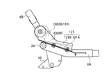
- FIG. 8 is a side view showing the vicinity of the follower supporting bracket according to the second embodiment, and corresponds to FIG. 4 in the first embodiment.
- FIG. 9 is a cross-sectional view taken along line YY of FIG.
- the curved portions 130 and 140 that are the convex portions 131 and 141 provided on the main body support bracket 121 and the follower support bracket 122 are set in the shock absorber 30.
- the main body support bracket 121 is fixed to the seat cushion frame 6A by fastening means such as bolts and nuts, and rises vertically from the fixing part 121A.
- the connecting portion 121B is formed in a substantially L shape in side view. Further, a curved portion 130 is formed which is provided in the vicinity of the bent portion 23 and is a convex portion 131 protruding in the left direction of the vehicle.
- the follower support bracket 122 is fixed to the side surface of the seat cushion frame 6A by fastening means such as bolts and nuts.
- the follower support bracket 122 is formed as a substantially L-shaped flat plate when viewed from the side, and is fixed to the side surface of the seat cushion frame with the plate thickness direction as the mounting direction. Further, a curved portion 140 that is a convex portion 141 protruding in the vehicle right direction is formed in the vicinity of the bent portion 25.
- a curved portion 140 having an arcuate cross section which is a convex portion 141 protruding in the vehicle right direction, is formed in the vicinity of the bent portion 25 in the follower portion supporting bracket 122.
- the curved portion 140 protrudes rightward in the vehicle, which is the outer side of the seat in the width direction, and is formed in a convex shape in a direction away from the occupant seated on the seat, as is apparent from FIG. Therefore, when a load is input to the seat back frame 6B toward the rear of the vehicle, as shown in FIG. 9, the curved portion 140 (the convex portion 141) extends flat in the longitudinal direction and is also deformed in the vehicle width direction.
- the follower support bracket 122 is deformed from a solid line shape to a two-dot chain line shape. 7 are also formed in the same cross-sectional shape as the convex portion 141 and the bending portion 140 in FIG. 7 and 8, the curved portion 130 (convex portion 131) and the curved portion 140 (convex portion 141) expand from the axial center of the main pipe 24 obliquely upward to the front. It is extended to.
- the main body support bracket 121 and the follower support bracket 122 are disposed at predetermined intervals from the outer surface of the seat cushion 4 or the seat back 5 toward the inside (downward and rearward). ing. For this reason, since a space can be secured between the occupant and the seat frame 6 in a normal state, the body portion support bracket 121 and the driven portion support bracket 122 do not feel uncomfortable, and the occupant has excellent sitting comfort. Can be maintained.
- the main body support bracket 121 and / or the follower support bracket 122 are deformed and absorb impact energy at a position away from the occupant. Therefore, the impact energy absorption efficiency is improved.
- the protrusions 131 and 141 provided on the main body support bracket 121 and the follower support bracket 122 and formed in a convex shape in a front view are set as the shock absorber 30. Yes.
- the convex portions 131, 141 extend to be flat and deform in the vehicle width direction.
- impact energy can be absorbed efficiently.
- the protrusions 131 and 141 having an allowance in advance and deforming to extend the protrusions 131 and 141 when a load is input, the impact energy can be absorbed more efficiently. .
- the convex portions 131 and 141 are formed in the curved portions 130 and 140 having an arcuate cross section, when the load in the vehicle front-rear direction is input to the seat back frame 6B, the curved portion 130 is obtained. , 140 can be deformed so that impact energy can be absorbed very efficiently.
Landscapes
- Engineering & Computer Science (AREA)
- Aviation & Aerospace Engineering (AREA)
- Transportation (AREA)
- Mechanical Engineering (AREA)
- Seats For Vehicles (AREA)
Abstract
Description
図1は第1の実施形態の折り畳み式シートを構成するシートフレームの斜視図、図2は図1の側面図、図3は図1のX-X線による断面図、図4は図1のリクライニング機構部を構成する従動部を支持する従動部支持用ブラケットが取り付けられた部位の要部拡大側面図、図5は車両前方からシートフレームに入力した荷重で本体部支持用ブラケットが車両後方向に変形して衝撃エネルギーを吸収する様子を示す断面図、図6は車両前方からシートフレームに入力した荷重で従動部支持用ブラケットが車両後方向に変形して衝撃エネルギーを吸収する様子を示す側面図である。
次いで、本発明の第2実施形態について説明するが、前述した第1実施形態と同一構造の部位には同一符号を付して、その説明を省略する。
Claims (7)
- シートクッションフレーム及び該シートクッションフレームに回動自在に支持されたシートバックフレームからなるシートフレームと、
リクライニング機構部を構成する本体部を支持すると共に、前記シートクッションフレームに固定される本体部支持用ブラケットと、
前記リクライニング機構部を構成する従動部を支持すると共に、前記シートクッションフレームに固定される従動部支持用ブラケットとを備え、
前記本体部支持用ブラケット及び従動部支持用ブラケットを、シートクッションまたはシートバックの外表面から内方側に向けて所定間隔をおいた位置に配設すると共に、
これらの本体部支持用ブラケット及び前記従動部支持用ブラケットの少なくともいずれかに、車両前後方向から前記シートフレームに入力した衝撃エネルギーを吸収する衝撃吸収部を設けたことを特徴とする折り畳み式シート。 - 請求項1に記載の折り畳み式シートであって、
前記衝撃吸収部は、前記本体部支持用ブラケット及び前記従動部支持用ブラケットの少なくともいずれかに設けられた、側面視で略L字状に折れ曲がった屈曲部であり、
車両前後方向から前記シートフレームに入力した荷重で前記屈曲部が開いて延びるように変形することによって衝撃エネルギーを吸収するように構成した折り畳み式シート。 - 請求項1または請求項2に記載の折り畳み式シートであって、
前記衝撃吸収部に切欠部を設けた折り畳み式シート。 - 請求項1から請求項3の何れか1項に記載の折り畳み式シートであって、
前記衝撃吸収部は、前記本体部支持用ブラケット及び前記従動部支持用ブラケットの少なくともいずれかに設けられた、正面視で車幅方向に突出する凸部である折り畳み式シート。 - 請求項4に記載の折り畳み式シートであって、
前記凸部は、正面視で車幅方向に略円弧状に湾曲した湾曲部である折り畳み式シート。 - 請求項1から請求項5の何れか1項に記載の折り畳み式シートであって、
前記衝撃吸収部を、前記各ブラケットと前記シートクッションフレームとの取付け点と、前記各ブラケットと前記本体部及び前記従動部との取付け点との間に設けた折り畳み式シート。 - 請求項1から請求項6の何れか1項に記載の折り畳み式シートであって、
前記従動部支持用ブラケットを平板形状とし、板厚方向を取付け方向として前記シートクッションフレーム側面に固定した折り畳み式シート。
Priority Applications (4)
| Application Number | Priority Date | Filing Date | Title |
|---|---|---|---|
| JP2010515798A JP5338813B2 (ja) | 2008-06-06 | 2009-03-27 | 折り畳み式シート |
| CN2009801209971A CN102056764B (zh) | 2008-06-06 | 2009-03-27 | 折叠式座椅 |
| US12/996,198 US8845019B2 (en) | 2008-06-06 | 2009-03-27 | Folding type seat |
| EP09758159.9A EP2298593B1 (en) | 2008-06-06 | 2009-03-27 | Folding seat |
Applications Claiming Priority (2)
| Application Number | Priority Date | Filing Date | Title |
|---|---|---|---|
| JP2008149335 | 2008-06-06 | ||
| JP2008-149335 | 2008-06-06 |
Publications (1)
| Publication Number | Publication Date |
|---|---|
| WO2009147892A1 true WO2009147892A1 (ja) | 2009-12-10 |
Family
ID=41397971
Family Applications (1)
| Application Number | Title | Priority Date | Filing Date |
|---|---|---|---|
| PCT/JP2009/056278 Ceased WO2009147892A1 (ja) | 2008-06-06 | 2009-03-27 | 折り畳み式シート |
Country Status (5)
| Country | Link |
|---|---|
| US (1) | US8845019B2 (ja) |
| EP (1) | EP2298593B1 (ja) |
| JP (1) | JP5338813B2 (ja) |
| CN (1) | CN102056764B (ja) |
| WO (1) | WO2009147892A1 (ja) |
Cited By (6)
| Publication number | Priority date | Publication date | Assignee | Title |
|---|---|---|---|---|
| CN103040267A (zh) * | 2011-10-14 | 2013-04-17 | 丰田纺织株式会社 | 座椅靠背框架 |
| CN103282234A (zh) * | 2011-01-07 | 2013-09-04 | 提爱思科技股份有限公司 | 收纳式后座 |
| US8888192B2 (en) | 2010-07-09 | 2014-11-18 | Toyota Boshoku Kabushiki Kaisha | Support structure of vehicle seat frame |
| JP2019137403A (ja) * | 2015-08-04 | 2019-08-22 | テイ・エス テック株式会社 | 乗物用シートフレーム及び乗物用シート |
| KR20200082913A (ko) * | 2018-12-31 | 2020-07-08 | 한화글로벌에셋 주식회사 | 자동차용 시트백 프레임 및 이의 제조방법 |
| JPWO2020202733A1 (ja) * | 2019-03-29 | 2020-10-08 |
Families Citing this family (25)
| Publication number | Priority date | Publication date | Assignee | Title |
|---|---|---|---|---|
| CN103661048B (zh) * | 2012-08-31 | 2017-08-25 | 重庆长安汽车股份有限公司 | 一种汽车后排座椅靠背骨架 |
| JP6007722B2 (ja) * | 2012-10-19 | 2016-10-12 | スズキ株式会社 | 車両用シートバック構造 |
| JP5895810B2 (ja) * | 2012-10-23 | 2016-03-30 | トヨタ紡織株式会社 | 車両用シート |
| JP6166643B2 (ja) * | 2013-01-23 | 2017-07-19 | 株式会社デルタツーリング | 車両用シート |
| FR3012385B1 (fr) * | 2013-10-30 | 2015-12-18 | Antolin Grupo Ing Sa | Siege escamotable anti deversement |
| FR3016862B1 (fr) * | 2014-01-24 | 2016-01-22 | Airbus Helicopters | Banquette pour aeronef comportant des baquets montes individuellement basculants vers le bas et a l'arriere de la banquette en cas de forte deceleration de l'aeronef |
| EP3277538B1 (en) * | 2015-03-31 | 2019-04-24 | Safran Seats USA LLC | Energy absorbing brackets for passenger seats |
| CA2936917C (en) | 2015-07-23 | 2018-05-22 | Dorel Juvenile Group, Inc. | Child restraint with energy management system |
| WO2017018491A1 (ja) | 2015-07-29 | 2017-02-02 | テイ・エス テック株式会社 | 車両用シートフレーム |
| CN105109373A (zh) * | 2015-08-27 | 2015-12-02 | 富卓汽车内饰(安徽)有限公司 | 汽车后排座椅固定结构 |
| CN105059160A (zh) * | 2015-08-27 | 2015-11-18 | 富卓汽车内饰(安徽)有限公司 | 汽车后排座椅 |
| DE102017208381A1 (de) | 2016-05-27 | 2017-11-30 | Ford Global Technologies, Llc | Befestigungshalter für konsole |
| DE102017200646B4 (de) * | 2017-01-17 | 2023-03-23 | Lear Corporation | Fahrzeug-Sitzanordnung und Easy-Entry-Löse-System |
| JP2018199383A (ja) * | 2017-05-26 | 2018-12-20 | トヨタ紡織株式会社 | 乗物用シートのバックフレームの取付構造 |
| US10525853B2 (en) * | 2018-03-06 | 2020-01-07 | Honda Motor Co., Ltd. | Apparatus for returning a stow strap to a retained access position |
| JP7470492B2 (ja) * | 2019-03-01 | 2024-04-18 | トヨタ紡織株式会社 | 乗物用シート |
| US11845367B2 (en) | 2019-04-18 | 2023-12-19 | Fisher & Company, Incorporated | Recliner heart having lubricant member |
| JP2021008205A (ja) * | 2019-07-01 | 2021-01-28 | 株式会社タチエス | 衝撃吸収装置及び乗物用シート |
| US11279488B2 (en) * | 2020-02-20 | 2022-03-22 | B/E Aerospace, Inc. | Seat assembly with sacrificial backrest breakover feature |
| US11607976B2 (en) * | 2020-03-06 | 2023-03-21 | Fisher & Company, Incorporated | Recliner mechanism having bracket |
| FR3116482B1 (fr) * | 2020-11-20 | 2022-11-11 | Faurecia Sieges Dautomobile | Banquette pour véhicule automobile utilitaire |
| US11766957B2 (en) | 2021-02-16 | 2023-09-26 | Fisher & Company, Incorporated | Release mechanism for seat recliner assembly |
| US11897372B2 (en) | 2021-05-06 | 2024-02-13 | Fisher & Company, Incorporated | Recliner heart having biasing members |
| US11850975B2 (en) | 2021-06-11 | 2023-12-26 | Fisher & Company, Incorporated | Vehicle seat recliner mechanism with welded spring |
| US11975639B2 (en) * | 2021-12-20 | 2024-05-07 | Lear Corporation | Seat back frame for impact deformation |
Citations (6)
| Publication number | Priority date | Publication date | Assignee | Title |
|---|---|---|---|---|
| JPS5638664U (ja) * | 1979-09-04 | 1981-04-11 | ||
| JPH04731B2 (ja) | 1984-06-14 | 1992-01-08 | Tokai Rika Co Ltd | |
| JPH0469222U (ja) * | 1990-10-23 | 1992-06-18 | ||
| JPH07132767A (ja) * | 1993-11-12 | 1995-05-23 | Mitsubishi Motors Corp | シ−ト装置 |
| JPH11348628A (ja) * | 1998-06-12 | 1999-12-21 | Araco Corp | 車両用シートバックフレーム |
| JP2001260723A (ja) * | 2000-03-21 | 2001-09-26 | Johnson Controls Automotive Systems Corp | 車両用シート |
Family Cites Families (20)
| Publication number | Priority date | Publication date | Assignee | Title |
|---|---|---|---|---|
| JPS5638664A (en) | 1980-04-02 | 1981-04-13 | Canon Inc | Character processor |
| FR2612151B1 (fr) * | 1987-03-12 | 1992-04-10 | Sicma Aero Seat | Structure a dispositif d'absorption d'energie et resistant a des efforts dynamiques formant pietement pour siege d'appareil de transport aerien et siege comportant une telle structure |
| US5303983A (en) * | 1992-04-30 | 1994-04-19 | Itt Corporation | Rotatable seat belt buckle mounting bracket for vehicle seat adjuster |
| US5700058A (en) * | 1996-06-18 | 1997-12-23 | Lear Corporation | Retention for vehicle seat and method of assembly |
| DE19853981B4 (de) * | 1997-11-21 | 2017-01-05 | Johnson Controls Components Gmbh & Co. Kg | Kraftfahrzeugsitz |
| DE19931894B4 (de) * | 1999-07-08 | 2005-06-30 | Key Safety Systems, Inc., Sterling Heights | Fahrzeugsitz |
| US6554356B1 (en) * | 1999-11-30 | 2003-04-29 | The C.E. White Co. | Shock absorbing vehicle seat frame |
| JP4000731B2 (ja) | 1999-12-28 | 2007-10-31 | スズキ株式会社 | シートバックフレーム構造 |
| US6491346B1 (en) * | 2000-06-01 | 2002-12-10 | Dow Global Technologies, Inc. | Seating system and method for making the same |
| CA2419236C (en) * | 2000-08-17 | 2009-01-20 | James Rudberg | Stowable seat assembly having a center pivot |
| US6543855B2 (en) * | 2001-08-24 | 2003-04-08 | Bae Industries, Inc. | Cup style spacer for attaching an upper arm to a seat frame forming a part of a seat integrated restraint mechanism |
| US6896324B1 (en) * | 2002-04-19 | 2005-05-24 | Adam Aircraft Industries | Hybrid composite-metal energy absorbing seat |
| US6709053B1 (en) * | 2002-09-30 | 2004-03-23 | Lear Corporation | Vehicle seat assembly with energy managing member |
| JP2005186670A (ja) * | 2003-12-24 | 2005-07-14 | Delta Kogyo Co Ltd | 車両用シート |
| WO2006093644A1 (en) * | 2005-02-28 | 2006-09-08 | Johnson Controls Technology Company | Energy absorption apparatus |
| US7360832B2 (en) * | 2006-01-12 | 2008-04-22 | Tachi-S Co. Ltd. | Impact absorption structure of vehicle seat |
| JP5223224B2 (ja) * | 2006-05-12 | 2013-06-26 | 日産自動車株式会社 | シートフレーム構造、シートおよびシートフレームの連結方法 |
| FR2904796B1 (fr) * | 2006-08-11 | 2008-10-24 | Faurecia Sieges Automobile | Dispositif d'absorption d'energie en cas de choc pour siege de vehicule automobile, siege et vehicule automobile comprenant le dispositif |
| DE102007018715A1 (de) * | 2007-04-20 | 2008-10-23 | Faurecia Autositze Gmbh | Fahrzeugsitz |
| US8132862B2 (en) * | 2009-01-29 | 2012-03-13 | Aisin Seiki Kabushiki Kaisha | Seat back frame for vehicle |
-
2009
- 2009-03-27 US US12/996,198 patent/US8845019B2/en active Active
- 2009-03-27 WO PCT/JP2009/056278 patent/WO2009147892A1/ja not_active Ceased
- 2009-03-27 EP EP09758159.9A patent/EP2298593B1/en active Active
- 2009-03-27 CN CN2009801209971A patent/CN102056764B/zh active Active
- 2009-03-27 JP JP2010515798A patent/JP5338813B2/ja active Active
Patent Citations (6)
| Publication number | Priority date | Publication date | Assignee | Title |
|---|---|---|---|---|
| JPS5638664U (ja) * | 1979-09-04 | 1981-04-11 | ||
| JPH04731B2 (ja) | 1984-06-14 | 1992-01-08 | Tokai Rika Co Ltd | |
| JPH0469222U (ja) * | 1990-10-23 | 1992-06-18 | ||
| JPH07132767A (ja) * | 1993-11-12 | 1995-05-23 | Mitsubishi Motors Corp | シ−ト装置 |
| JPH11348628A (ja) * | 1998-06-12 | 1999-12-21 | Araco Corp | 車両用シートバックフレーム |
| JP2001260723A (ja) * | 2000-03-21 | 2001-09-26 | Johnson Controls Automotive Systems Corp | 車両用シート |
Cited By (15)
| Publication number | Priority date | Publication date | Assignee | Title |
|---|---|---|---|---|
| DE102011078688B4 (de) | 2010-07-09 | 2021-11-04 | Toyota Boshoku K.K. | Tragkonstruktion für einen fahrzeugsitzrahmen |
| US8888192B2 (en) | 2010-07-09 | 2014-11-18 | Toyota Boshoku Kabushiki Kaisha | Support structure of vehicle seat frame |
| CN103282234A (zh) * | 2011-01-07 | 2013-09-04 | 提爱思科技股份有限公司 | 收纳式后座 |
| US9126503B2 (en) | 2011-01-07 | 2015-09-08 | Ts Tech Co., Ltd. | Stowable rear seat |
| JP2013085601A (ja) * | 2011-10-14 | 2013-05-13 | Toyota Boshoku Corp | シートバックフレーム |
| CN103040267B (zh) * | 2011-10-14 | 2016-08-03 | 丰田纺织株式会社 | 座椅靠背框架 |
| CN103040267A (zh) * | 2011-10-14 | 2013-04-17 | 丰田纺织株式会社 | 座椅靠背框架 |
| JP2019137403A (ja) * | 2015-08-04 | 2019-08-22 | テイ・エス テック株式会社 | 乗物用シートフレーム及び乗物用シート |
| JP6989787B2 (ja) | 2015-08-04 | 2022-01-12 | テイ・エス テック株式会社 | 乗物用シートフレーム及び乗物用シート |
| KR20200082913A (ko) * | 2018-12-31 | 2020-07-08 | 한화글로벌에셋 주식회사 | 자동차용 시트백 프레임 및 이의 제조방법 |
| KR102404249B1 (ko) * | 2018-12-31 | 2022-05-30 | 한화글로벌에셋 주식회사 | 자동차용 시트백 프레임 |
| JPWO2020202733A1 (ja) * | 2019-03-29 | 2020-10-08 | ||
| WO2020202733A1 (ja) * | 2019-03-29 | 2020-10-08 | 株式会社タチエス | 車両用シート |
| JP7391089B2 (ja) | 2019-03-29 | 2023-12-04 | 株式会社タチエス | 車両用シート |
| US12049160B2 (en) | 2019-03-29 | 2024-07-30 | Tachi-S Co., Ltd. | Vehicle seat |
Also Published As
| Publication number | Publication date |
|---|---|
| JPWO2009147892A1 (ja) | 2011-10-27 |
| US8845019B2 (en) | 2014-09-30 |
| EP2298593A1 (en) | 2011-03-23 |
| CN102056764B (zh) | 2013-09-25 |
| CN102056764A (zh) | 2011-05-11 |
| EP2298593A4 (en) | 2015-05-20 |
| EP2298593B1 (en) | 2018-05-09 |
| US20110074189A1 (en) | 2011-03-31 |
| JP5338813B2 (ja) | 2013-11-13 |
Similar Documents
| Publication | Publication Date | Title |
|---|---|---|
| JP5338813B2 (ja) | 折り畳み式シート | |
| JP5463659B2 (ja) | 車両用シートのシートクッション構造 | |
| JP5930304B2 (ja) | 車両用シート | |
| JP5669567B2 (ja) | 乗物用シート | |
| JP5013601B2 (ja) | 車両用シートのベースブラケット構造 | |
| JP6169134B2 (ja) | 車両用シートレール | |
| JP4539435B2 (ja) | 車両用シート | |
| JP2012106578A (ja) | シートバックボード及びこれを用いた車両用シート | |
| JPH07132767A (ja) | シ−ト装置 | |
| JP6519389B2 (ja) | 乗物用シートフレーム | |
| JP6959551B2 (ja) | 乗物用シート | |
| JP2011255860A (ja) | 自動車のシートバックの支持構造 | |
| JP5989856B2 (ja) | 乗物用シート | |
| JP5629205B2 (ja) | 乗物用シート | |
| JP5643636B2 (ja) | 乗物用シート | |
| JP5701592B2 (ja) | 乗物用シート | |
| JP5629204B2 (ja) | 乗物用シート | |
| JP5863509B2 (ja) | 車両用シート装置 | |
| JP2010264961A (ja) | 車両用シートのスライドレール変形防止構造 | |
| JP7089151B2 (ja) | 車両用シート | |
| JP5580727B2 (ja) | 乗物用シート | |
| JP7769204B2 (ja) | 乗物用シート | |
| JP5634855B2 (ja) | 乗物用シート | |
| JP5584610B2 (ja) | 乗物用シート | |
| JP5094105B2 (ja) | 自動車のシート装置 |
Legal Events
| Date | Code | Title | Description |
|---|---|---|---|
| WWE | Wipo information: entry into national phase |
Ref document number: 200980120997.1 Country of ref document: CN |
|
| 121 | Ep: the epo has been informed by wipo that ep was designated in this application |
Ref document number: 09758159 Country of ref document: EP Kind code of ref document: A1 |
|
| WWE | Wipo information: entry into national phase |
Ref document number: 2010515798 Country of ref document: JP |
|
| WWE | Wipo information: entry into national phase |
Ref document number: 12996198 Country of ref document: US |
|
| NENP | Non-entry into the national phase |
Ref country code: DE |
|
| WWE | Wipo information: entry into national phase |
Ref document number: 2009758159 Country of ref document: EP |