WO2009148013A1 - Procédé de nettoyage de sonde dans un dispositif de distribution d'analyte, dispositif de distribution d'analyte et analyseur automatique - Google Patents
Procédé de nettoyage de sonde dans un dispositif de distribution d'analyte, dispositif de distribution d'analyte et analyseur automatique Download PDFInfo
- Publication number
- WO2009148013A1 WO2009148013A1 PCT/JP2009/059972 JP2009059972W WO2009148013A1 WO 2009148013 A1 WO2009148013 A1 WO 2009148013A1 JP 2009059972 W JP2009059972 W JP 2009059972W WO 2009148013 A1 WO2009148013 A1 WO 2009148013A1
- Authority
- WO
- WIPO (PCT)
- Prior art keywords
- sample
- dispensing
- probe
- cleaning
- dispensing probe
- Prior art date
- Legal status (The legal status is an assumption and is not a legal conclusion. Google has not performed a legal analysis and makes no representation as to the accuracy of the status listed.)
- Ceased
Links
Images



Classifications
-
- G—PHYSICS
- G01—MEASURING; TESTING
- G01N—INVESTIGATING OR ANALYSING MATERIALS BY DETERMINING THEIR CHEMICAL OR PHYSICAL PROPERTIES
- G01N35/00—Automatic analysis not limited to methods or materials provided for in any single one of groups G01N1/00 - G01N33/00; Handling materials therefor
- G01N35/10—Devices for transferring samples or any liquids to, in, or from, the analysis apparatus, e.g. suction devices, injection devices
- G01N35/1004—Cleaning sample transfer devices
Definitions
- the present invention relates to a probe cleaning method, a sample dispensing device, and an automatic analyzer for a sample dispensing device.
- an automatic analyzer is provided with a dispensing device for dispensing a liquid sample such as a specimen or a reagent (see, for example, Patent Document 1).
- a pipe filled with extruded water is connected between the dispensing pump and a dispensing probe for dispensing a liquid sample containing a specimen or a reagent, and the dispensing pump is moved up and down to move the extruded water.
- the liquid sample is dispensed by sucking the liquid sample into the dispensing probe and discharging the sucked liquid sample.
- the dispensing device avoids carryover of the liquid sample by washing the inside and outside of the dispensing probe each time a liquid sample is dispensed, and one washing for each dispensing. Based on.
- the specimens dispensed by the specimen dispensing apparatus range from a high viscosity such as blood to a low viscosity such as urine.
- the conventional analyzer may be insufficiently cleaned depending on the type of specimen, that is, the analysis item.
- the present invention has been made in view of the above, and an object of the present invention is to provide a probe cleaning method, a sample dispensing device, and an automatic analyzer for a sample dispensing device capable of sufficiently washing a dispensing probe.
- the probe cleaning method of the present invention is a sample dispensing device that dispenses the sample by aspirating the sample into the dispensing probe and discharging the aspirated sample.
- An analysis item determination step for determining whether or not the dispensing probe dispenses a sample related to a specific analysis item; and the dispensing probe separates a sample related to a specific analysis item.
- the cleaning step includes a plurality of modes for cleaning at least an outer wall surface of the dispensing probe according to the specific analysis item.
- the sample dispensing apparatus of the present invention dispenses the sample by aspirating the sample with a dispensing probe and discharging the aspirated sample.
- An analysis item determination unit that determines whether a sample to be dispensed by the dispensing probe is a sample related to a specific analysis item, and a determination result of the analysis item determination unit based on the determination result of the analysis item determination unit
- the dispense probe is controlled to a normal washing mode in which the inner and outer wall surfaces of the dispensing probe are washed after the sample is discharged.
- the dispensing probe Characterized by comprising a mode control unit for controlling a special cleaning mode for cleaning the outer wall surface.
- the mode control means has a plurality of modes for cleaning at least an outer wall surface of the dispensing probe according to the specific analysis item.
- the automatic analyzer of the present invention reacts a plurality of different liquid samples including a specimen and a plurality of reagents, and measures the optical characteristics of the reaction liquid.
- An automatic analyzer for analyzing the reaction solution wherein the sample is dispensed into a reaction container using the sample dispensing device, the dispensing probe into which the sample is dispensed is washed, and the reaction solution is It is characterized by optical analysis.
- the probe cleaning method of the sample dispensing apparatus of the present invention includes an analysis item determination step for determining whether or not the dispensing probe dispenses a sample related to a specific analysis item, and the dispensing probe relates to a specific analysis item.
- an analysis item determination step for determining whether or not the dispensing probe dispenses a sample related to a specific analysis item, and the dispensing probe relates to a specific analysis item.
- the sample dispensing apparatus of the present invention includes an analysis item determination unit that determines whether or not the sample to be dispensed by the dispensing probe is a sample related to a specific analysis item, and an analysis item Based on the determination result of the determination means, when the dispensing probe dispenses a sample related to a normal analysis item, it is controlled to the normal washing mode in which the inner and outer walls of the dispensing probe are washed after the sample is discharged.
- Dispensing probes are related to specific analysis items When a sample is dispensed, after the dispensing probe is washed, before the next new sample is aspirated, at least the outer wall surface of the dispensing probe is washed, the next new sample is discharged, and then the dispensing probe Mode control means for controlling to a special cleaning mode for cleaning the inner and outer wall surfaces.
- the automatic analyzer of the present invention dispenses a sample into a reaction container using the sample dispensing device, cleans a dispensing probe dispensed with the sample, and optically analyzes the reaction solution. For this reason, the probe cleaning method, sample dispensing apparatus, and automatic analyzer of the sample dispensing apparatus of the present invention have the effect that the dispensing probe can be sufficiently washed.
- FIG. 1 is a schematic configuration diagram showing an example of an automatic analyzer to which a probe cleaning method for a specimen dispensing apparatus of the present invention is applied.
- FIG. 2 is a schematic configuration diagram of a sample dispensing device provided in the automatic analyzer shown in FIG.
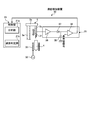
- FIG. 3 is a diagram showing a schematic configuration of a liquid level detection device provided in the sample dispensing device.
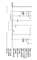
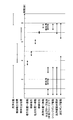
- FIG. 4 is a diagram illustrating an example of a position where a dispensing probe exists and an operation timing of the dispensing probe in the probe cleaning method of the sample dispensing apparatus.
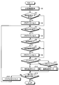
- FIG. 5 is a flowchart for explaining the probe cleaning method of the specimen dispensing apparatus of the present invention.
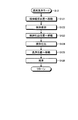
- FIG. 6 is a flowchart for explaining a special cleaning mode in the probe cleaning method of the specimen dispensing apparatus of the present invention.
- FIG. 7 is a flowchart for explaining a normal cleaning mode in the probe cleaning method of the specimen dispensing apparatus of the present invention.
- FIG. 8 is a diagram illustrating another example of the special cleaning mode in the probe cleaning method of the specimen dispensing apparatus.
- FIG. 1 is a schematic configuration diagram showing an example of an automatic analyzer to which a probe cleaning method for a specimen dispensing apparatus of the present invention is applied.
- FIG. 2 is a schematic configuration diagram of a sample dispensing device provided in the automatic analyzer shown in FIG.
- FIG. 3 is a diagram showing a schematic configuration of a liquid level detection device provided in the sample dispensing device.
- the automatic analyzer 1 includes a sample table 3, a sample dispensing device 5, a cuvette wheel 7, a photometric device 9, a washing device 10, a stirring device 11, a reagent dispensing device 12, A reagent table 13 and a second reagent table 17 are provided.
- the sample table 3 is rotated in the direction of the arrow shown in FIG. 1 by the driving means, and a plurality of storage chambers 3a are provided on the outer periphery at regular intervals along the circumferential direction.
- a sample container 4 storing a sample is detachably stored in each storage chamber 3a.
- the sample dispensing device 5 is means for dispensing a sample as a liquid sample into the reaction vessel 8 held by the cuvette wheel 7 and includes a liquid level detection device 30.
- the sample dispensing device 5 sequentially dispenses samples from the plurality of sample containers 4 on the sample table 3 to the reaction container 8.
- the sample dispensing device 5 includes a column 5 a, an arm 5 b, a dispensing probe 5 c, and a dispensing control unit 50.
- the support column 5a is rotated about the axis in the horizontal plane and is moved up and down in the vertical direction.
- the vertical movement of the column 5 a is controlled with high accuracy by a driving means such as a stepping motor whose driving is controlled based on a liquid level position signal input from the liquid level detection device 30 to the control unit 21.
- the arm 5b is supported by the column 5a.
- the dispensing probe 5 c is supported by the arm 5 b, connected to the extruded water tank 52 by the pipe 51, and filled with the extruded water together with the pipe 51.
- Dispensing control unit 50 moves up and down and rotates the support column 5 a, drives the pressurizing pump 53 and the driving unit 56 a associated with sample dispensing, and dispenses electromagnetic valves 55 and cleaning electromagnetics.
- Dispensing control means using an electronic control unit (ECU) or the like that controls switching of opening and closing of the valve 62, and includes a mode control unit 50a and an analysis item determination unit 50b.
- ECU electronice control unit
- the mode control unit 50a is connected to the control unit 21 and cleans the dispensing probe 5c in the normal cleaning mode based on the determination result of the analysis item determination unit 50b or special cleaning. It is a mode control means for controlling whether the washing is performed in the mode and controlling the operation of the drive unit 56a for driving the syringe pump 56.
- the analysis item determination unit 50b is an analysis item determination unit that determines whether the sample dispensed by the dispensing probe 5c is a sample related to a specific analysis item.
- the analysis item determination unit 50b stores a specific analysis item name for which the cleaning mode of the dispensing probe 5c should be the special cleaning mode, and is included in the analysis information input from the host computer via the control unit 21.
- the mode control unit 50a specially dispenses the dispensing probe 5c until a series of analysis is completed. Wash in wash mode.
- the normal cleaning mode of the dispensing probe 5c refers to a mode in which the inner and outer walls of the dispensing probe 5c are cleaned after the sample is discharged
- the special cleaning mode refers to the sample in addition to the cleaning in the normal cleaning mode.
- This mode is a mode in which at least the outer wall surface of the dispensing probe 5c that has been washed after the previous dispensing is washed before suction.
- the specimen dispensing device 5 is provided with a pressure pump 53, an air trap 54, a dispensing electromagnetic valve 55 including a three-way valve, and a syringe pump 56 in order from the extruded water tank 52 side. It has been.
- the dispensing solenoid valve 55 is connected to a return pipe 51 a that returns the extruded water pumped by the pressurizing pump 53 to the extruded water tank 52.
- the syringe pump 56 moves the push water in the dispensing probe 5c by reciprocating the pusher by the driving unit 56a, aspirates the specimen, and discharges the sucked specimen.
- a cleaning tank 6 is disposed between the sample table 3 and the cuvette wheel 7.
- the cleaning tank 6 is connected between a pressurizing pump 53 formed of a gear pump and a pipe 51 connecting an air trap 54 by a pipe 61 provided with a cleaning electromagnetic valve 62 formed of a three-way valve.
- the inside and outside of the dispensing probe 5c into which the specimen has been dispensed is washed with extruded water.
- the cleaning electromagnetic valve 62 is connected to a return pipe 61 a that returns the extruded water pumped by the pressurizing pump 53 to the extruded water tank 52.
- the cuvette wheel 7 is rotated in the direction of the arrow shown in FIG. 1 by driving means different from the sample table 3, and a plurality of recesses 7a for arranging the reaction vessels 8 along the circumferential direction are provided at equal intervals on the outer periphery. .
- the cuvette wheel 7 is formed with openings through which the measurement light passes on both radial sides of each recess 7a.
- the cuvette wheel 7 rotates clockwise (1 turn-1 reaction vessel) / 4 minutes in one cycle and rotates counterclockwise by one of the recesses 7a in four cycles.
- a photometric device 9 On the outer periphery of the cuvette wheel 7, a photometric device 9, a cleaning device 10, and a stirring device 11 are arranged.
- the reaction vessel 8 is a very small cuvette with a capacity of several ⁇ L to several tens ⁇ L, and is a transparent material that transmits the analysis light emitted from the light source of the photometric device 9, such as glass containing heat-resistant glass, cyclic olefin, polystyrene, etc.
- the synthetic resin is used.
- the photometric device 9 is disposed near the outer periphery of the cuvette wheel 7, and a light source that emits analysis light for analyzing the liquid held in the reaction vessel 8 and the analysis light that has passed through the liquid are dispersed. And a light receiver for receiving light.
- the light source and the light receiver are arranged at positions facing each other in the radial direction across the concave portion 7 a of the cuvette wheel 7.
- the cleaning device 10 has a discharging means for discharging the liquid and the cleaning liquid from the reaction vessel 8 and a cleaning liquid dispensing means.
- the cleaning apparatus 10 dispenses the cleaning liquid after discharging the liquid after the photometry from the reaction vessel 8 after the completion of the photometry.
- the cleaning apparatus 10 cleans the inside of the reaction vessel 8 by repeating the dispensing and discharging operations of the cleaning liquid a plurality of times. The reaction vessel 8 washed in this way is used again for analysis of a new specimen.
- the stirrer 11 stirs the specimen or reagent dispensed into the reaction vessel 8 with, for example, a stir bar. However, when it is necessary to stir the liquid held in the reaction vessel 8 in a non-contact manner, the stirring device 11 attaches a surface acoustic wave element to the reaction vessel 8 and stirs it with sound waves generated by the surface acoustic wave element. May be.
- the reagent dispensing device 12 is a means for dispensing a reagent into a plurality of reaction containers 8 held by the cuvette wheel 7, and as shown in FIG. 1, predetermined reagent of the first reagent table 13 and the second reagent table 17 is provided. Reagents are sequentially dispensed from the reagent containers 14 and 18 into the reaction container 8.
- the first reagent table 13 is rotated in the direction of the arrow shown in FIG. 1 by driving means different from the sample table 3 and the cuvette wheel 7, and a plurality of storage chambers 13a formed in a fan shape are provided along the circumferential direction.
- the first reagent container 14 is detachably stored in each of the storage chambers 13a.
- Each of the plurality of first reagent containers 14 holds a predetermined first reagent in accordance with each inspection item, and an information recording medium (not shown) such as a bar code label on which information related to the stored first reagent is recorded on the outer surface. Z) is affixed.
- the cuvette wheel 7 and the 1st reagent table 13 it is comprised similarly to the washing tank 6, and the washing
- a tank 15 is arranged. Then, on the outer periphery of the first reagent table 13, the information such as the reagent type, lot, and expiration date recorded on the information recording medium attached to each first reagent container 14 is read and output to the control unit 21. A device 16 is installed.
- the second reagent table 17 is arranged in the vicinity of the cuvette wheel 7 and the first reagent table 13 and is rotated in the direction of the arrow shown in FIG. As shown in FIG. 1, a plurality of second reagent containers 18 holding the second reagent are detachably accommodated in a plurality of storage chambers 17a provided in the circumferential direction. Between the cuvette wheel 7 and the second reagent table 13, there is disposed a washing tank 19 for washing the inside and outside of the reagent probe into which the second reagent has been dispensed with extruded water.
- the dispensing position of the first reagent, the dispensing position of the second reagent, the washing tank 15 and the washing tank 19 on the cuvette wheel 7 are arranged on the movement path of the dispensing probe of the reagent dispensing apparatus 12. Yes. Then, on the outer periphery of the second reagent table 17, the information such as the reagent type, lot, and expiration date recorded on the information recording medium attached to each second reagent container 18 is read and output to the control unit 21. A device 20 is installed.
- the control unit 21 uses, for example, a microcomputer having a storage function for storing analysis results, and includes a sample table 3, a sample dispensing device 5, a cuvette wheel 7, a photometric device 9, a washing device 10, a stirring device 11, The reagent dispensing device 12, the first reagent table 13, the reading device 16, the second reagent table 17, the reading device 20, the input unit 22, the display unit 23, and the like are connected.
- the control unit 21 controls the operation of each unit of the automatic analyzer 1 based on the analysis information including the cleaning mode of the dispensing probe 5c input from the host computer or the input unit 22, and the reading devices 16 and 20 Based on the information read from the information recording medium, if the reagent lot or expiration date is outside the set range, the automatic analyzer 1 is controlled to stop the analysis work or a warning is issued to the operator.
- the control unit 21 includes an analysis unit 21a and a liquid level determination unit 21b.
- the analysis unit 21a stores analysis information such as a specimen or reagent identification number, a patient identification number, an analysis item, necessity of reexamination, a cleaning mode of the dispensing probe 5c, and the like input from the host computer, and the photometric device 9
- the component concentration of the specimen is analyzed from the absorbance (optical characteristics) of the reaction liquid of the specimen and the reagent in the cuvette C, which is obtained based on the light quantity measured by, and the analysis result is stored.
- the analysis result includes a previous analysis value (hereinafter referred to as “previous value”) regarding the same analysis item of the same patient sample.
- the liquid level determination unit 21b determines whether or not the liquid level is based on the voltage of the signal output from the comparator 39 of the liquid level detection device 30.
- the liquid level determination unit 21b receives an input from a driving unit that causes the column 5a of the sample dispensing apparatus 5 to move up and down.
- the position in the vertical direction of the specimen liquid level with reference to a predetermined position is obtained based on the drive signal, and the liquid level position signal is output to the mode control unit 50a together with the liquid level detection signal input from the liquid level detection device 30.
- the input unit 22 is a part for performing input operations such as selection of the number of specimens, test items, normal cleaning mode or special cleaning mode to the control unit 21, and for example, a keyboard or a mouse is used.
- the display unit 23 displays an alarm including an insufficient sample based on the analysis content including the analysis result and the vertical position of the sample liquid level obtained by the liquid level determination unit 21b, and a display panel or the like is used.
- the liquid level detection device 30 is a capacitance type device that detects the liquid level of the sample contained in the sample container 4 when the sample is dispensed by the sample dispensing device 5, and as shown in FIG.
- a movable electrode 31 detachably attached to the dispensing probe 5c, a fixed electrode 33 disposed in the vicinity of the sample container 4, and a processing substrate 35 accommodated in the arm 5b are provided.
- the movable electrode 31 serves as a receiving electrode for an oscillation signal induced by the fixed electrode 33, and is made of, for example, a conductive metal such as stainless steel (SUS).
- the movable electrode 31 is attached to the dispensing probe 5c by shifting the lower end of the dispensing probe 5c downward from the lower end of the electrode. This downward shift amount is set to the amount of change in the liquid level that accompanies at least one dispensing of the sample contained in the sample container 4.
- the movable electrode 31 is further pushed into the sample by a predetermined amount from the position of the detected liquid level when the sample is aspirated.
- the movable electrode 31 may be easily drained by forming a coating having lyophobic properties on a specimen such as a fluororesin containing a carbon fiber or an organic conductive transparent sheet on the surface.
- the fixed electrode 33 is arranged inside each storage chamber 3 a of the sample table 3, and an AC signal for detecting the liquid level of the sample stored in the sample container 4 is applied from the oscillator 32.
- the processing substrate 35 has an amplifier 36, a diode 37, and a comparator 39 as shown in FIG.
- the amplifier 36 connects the stirring movable electrode 31 and the control unit 21 via a diode 37 and a comparator 39.
- the amplifier 36 introduces the oscillation signal applied to the fixed electrode 33 by the oscillator 32 through the specimen and the movable electrode 31, and the oscillation signal. Amplify.
- the diode 37 rectifies and smoothes the oscillation signal amplified by the amplifier 36 in cooperation with the capacitor 38, and outputs the smoothed signal to the comparator 39.
- the comparator 39 determines whether or not the liquid level has been detected by comparing the input smoothing signal (voltage) with a separately input reference value signal (voltage). At this time, the comparator 39 outputs a liquid level detection signal to the control unit 21 when the input smoothing signal (voltage) is larger than the reference value signal (voltage).
- the reagent dispensing device 12 transfers the first reagent from the first reagent container 14 to the plurality of reaction containers 8 conveyed along the circumferential direction by the rotating cuvette wheel 7. Dispense sequentially.
- the reaction container 8 into which the first reagent has been dispensed is conveyed along the circumferential direction by the cuvette wheel 7, and the specimens are sequentially dispensed from the plurality of specimen containers 4 held on the specimen table 3 by the specimen dispensing device 5.
- reaction container 8 into which the sample has been dispensed is conveyed to the stirring device 11 by the cuvette wheel 7, and the dispensed first reagent and the sample are sequentially stirred and reacted to become a reaction solution.
- the second reagent is sequentially dispensed from the second reagent container 18 by the second reagent table 17 while the reaction container 8 into which the first reagent has been dispensed is conveyed along the circumferential direction by the cuvette wheel 7.
- the reaction solution reacts with the second reagent.
- the reaction vessel 8 passes through the photometric device 9 a plurality of times as the cuvette wheel 7 rotates, and the analysis light emitted from the light source is transmitted.
- the reaction liquid of the first reagent and the sample and the reaction liquid of the reaction reagent and the second reagent in the reaction container 8 are measured by the light receiving unit, and the component concentration and the like are analyzed by the control unit 21 based on the photometric value. Is done.
- the reaction container 8 that has been analyzed is washed by the washing apparatus 10 and then used again for analyzing the specimen.
- the sample dispensing device 5 dispenses the sample into the reaction container 8 according to the timing chart shown in FIG. 4 as an example, and cleans the dispensed probe 5c after dispensing.
- FIG. 4 shows an example of the position where the dispensing probe 5c exists and the operation timing of the dispensing probe 5c.
- the dispensing probe 5c dispenses into the reaction vessel 8 with 9 seconds per sample as one cycle, and performs washing after dispensing.
- the washing position that is, the washing tank 6 is used. Is a position (standby position) when the operation starts and when the operation ends. During this time, dispensing of the first reagent and cleaning of the reagent dispensing probe and dispensing of the second reagent and washing of the reagent dispensing probe are performed.
- the dispensing probe 5c is cleaned at the cleaning position as shown in FIG.
- the syringe pump 56 is driven by the mode control unit 50a.
- the cleaning electromagnetic valve 62 of the cleaning tank 6 is opened.
- the dispensing probe 5c arranged in the cleaning tank 6 is internally and externally formed by the extrusion water supplied from the syringe pump 56 through the pipe 51 and the extrusion water fed from the pressure pump 53 through the pipe 61. Is cleaned (pre-cleaning).
- the dispensing probe 5c is moved to the specimen aspirating position and aspirates the specimen. At this time, the sample is aspirated from the sample container 4 of the sample table 3. Next, the dispensing probe 5 c is moved to the sample discharge position and discharges the sample to the reaction container 8.
- the dispensing probe 5c is moved to the cleaning position (cleaning tank 6), and the inside and outside are cleaned by the extrusion water at the cleaning position in the same manner as the pre-cleaning (post-cleaning).
- the specimen dispensing device 5 cleans the dispensing probe 5c as described above.
- the pre-cleaning described above is not performed, and only the post-cleaning is performed.
- the dispensing control unit 50 is as follows. Then, the cleaning mode of the dispensing probe 5c is controlled to the normal cleaning mode or the special cleaning mode, and the cleaning of the dispensing probe 5c is executed. The control of the normal cleaning mode and the special cleaning mode executed by the dispensing control unit 50 at this time will be described below with reference to the flowchart shown in FIG.
- the dispensing control unit 50 cleans the dispensing probe 5c in the normal cleaning mode when both the flags X and Y are 0, and the dispensing probe in the special cleaning mode when at least one of the flags X and Y is 1. Wash 5c.
- the dispensing control unit 50 determines whether or not the cleaning mode of the dispensing probe 5c is set to the special cleaning mode from the acquired analysis information (step S2).
- the analysis item determination unit 50b executes the determination of the special cleaning mode.
- the dispensing control unit 50 proceeds to step S4.
- the dispensing control unit 50 determines whether or not there is a previous value for the same analysis item of the same patient sample from the acquired analysis information (step S6). When there is no previous value (step S6, No), the dispensing control unit 50 proceeds to step S9. On the other hand, when there is a previous value (step S6, Yes), the dispensing control unit 50 determines whether or not the previous value is an abnormal value (step S7).
- step S11, No the dispensing control unit 50 dispenses the sample and cleans the dispensing probe 5c in the normal cleaning mode (step S12). Thereafter, the dispensing control unit 50 determines whether dispensing of all the samples has been completed based on the analysis information acquired from the control unit 21 (step S13). When the dispensing of all the samples has been completed (step S13, Yes), the dispensing control unit 50 ends the control related to the probe cleaning method of the sample dispensing device 5.
- the dispensing control unit 50 executes control related to the probe cleaning method of the sample dispensing apparatus 5 as described above.
- the dispensing control unit 50 executes the special cleaning mode (step S10) of the dispensing probe 5c according to the timing shown in FIG.
- the special cleaning mode executed under the control of the dispensing control unit 50 will be described with reference to the flowchart shown in FIG.
- the dispensing control unit 50 controls the driving unit 56a to pre-clean the dispensing probe 5c (step S101). At this time, as shown in FIG. 4, the dispensing probe 5 c is arranged at a cleaning position where the cleaning tank 6 is located at the timing of the pre-cleaning. Next, the dispensing control unit 50 moves the dispensing probe 5c to the sample aspirating position of the sample table 3 by controlling the raising / lowering operation and the rotating operation of the support column 5a of the sample dispensing device 5 (step S102).
- the dispensing control unit 50 controls the driving unit 56a to cause the dispensing probe 5c to suck the sample stored in the sample container 4 (step S103). Thereafter, the dispensing control unit 50 controls the raising and lowering operation and the pivoting operation of the column 5a of the sample dispensing device 5 to move the dispensing probe 5c to the sample discharge position of the cuvette wheel 7 (Step S104).
- the dispensing control unit 50 controls the driving unit 56a to discharge the sample sucked by the dispensing probe 5c into the reaction container 8 (step S105).
- the dispensing control unit 50 controls the lifting / lowering operation and the pivoting operation of the column 5a of the sample dispensing device 5 to move the dispensing probe 5c to the cleaning position where the cleaning tank 6 is located (Step S106).
- the dispensing control unit 50 controls the driving unit 56a to post-clean the dispensing probe 5c after the sample dispensing (step S107). In this way, the dispensing control unit 50 ends the special cleaning mode of the dispensing probe 5c.
- the dispensing probe 5c is pre-washed, so that the dispensing probe 5c that has been dispensed with a different sample last time and later washed again before dispensing this new sample again. Washing is performed twice during one cycle from dispensing of one specimen to washing after dispensing.
- the cleaning efficiency of the dispensing probe can be improved by switching the cleaning mode according to the analysis item, and the carry-over of the sample can be reduced to almost none.
- the dispensing probe 5c is washed with extruded water, so that a waste liquid treatment facility is not required as compared with the case where washing is performed using a detergent, and the waste liquid can be treated inexpensively and environmentally. It has the advantage of being able to.
- the dispensing control unit 50 controls the lifting / lowering operation and the pivoting operation of the column 5 a of the sample dispensing device 5 to move the dispensing probe 5 c to the sample aspirating position of the sample table 3. (Step S121).
- the dispensing control unit 50 controls the driving unit 56a to cause the dispensing probe 5c to suck the sample stored in the sample container 4 (step S122). At this time, the dispensing control unit 50 also controls the lifting / lowering operation and the pivoting operation of the column 5a of the sample dispensing device 5 accompanying the sample aspiration. Next, the dispensing control unit 50 controls the lifting and lowering operations and the pivoting operation of the column 5a of the sample dispensing device 5 to move the dispensing probe 5c to the sample discharge position of the cuvette wheel 7 (Step S123).
- the dispensing control unit 50 controls the drive unit 56a to discharge the sample sucked into the dispensing probe 5c into the reaction container 8 (step S124). At this time, the dispensing control unit 50 also controls the raising / lowering operation and the rotating operation of the support column 5a of the sample dispensing device 5 accompanying the ejection of the sample. Next, the dispensing control unit 50 moves the dispensing probe 5c to the cleaning position where the cleaning tank 6 is located by controlling the lifting / lowering operation and the rotating operation of the column 5a of the sample dispensing device 5 (step S125).
- the dispensing control unit 50 controls the driving unit 56a to wash the dispensing probe 5c after sample dispensing (step S126). In this way, the dispensing control unit 50 ends the normal cleaning mode of the dispensing probe 5c.
- the special cleaning mode executed under the control of the dispensing control unit 50 cleans the inside and outside of the dispensing probe 5c once by executing pre-cleaning at the cleaning position.
- the special cleaning mode is pre-cleaning using the time that the dispensing probe 5c is waiting at the cleaning position
- the pre-cleaning of the dispensing probe 5c may be performed a plurality of times as shown in FIG. .
- the cleaning time may be arbitrarily set as long as the dispensing probe 5c is waiting at the cleaning position.
- the special cleaning mode may be cleaning only outside the dispensing probe 5c as pre-cleaning at the cleaning position.
- the mode control unit 50 a is provided in the sample dispensing device 5, but may be provided in the control unit 21 of the automatic analyzer 1 together with the dispensing control unit 50.
- the automatic analyzer 1 dispenses the first reagent and the second reagent by the reagent dispensing device 12, but the two reagents of the reagent dispensing device for the first reagent and the reagent dispensing device for the second reagent are used.
- a dispensing device may be provided.
- the said embodiment demonstrated the case where the dispensing probe 5c of the sample dispensing apparatus 5 was wash
- the probe cleaning method, the sample dispensing apparatus, and the automatic analyzer of the sample dispensing apparatus of the present invention are suitable for sufficiently washing the dispensing probe during sample dispensing.
Landscapes
- Physics & Mathematics (AREA)
- Health & Medical Sciences (AREA)
- Life Sciences & Earth Sciences (AREA)
- Chemical & Material Sciences (AREA)
- Analytical Chemistry (AREA)
- Biochemistry (AREA)
- General Health & Medical Sciences (AREA)
- General Physics & Mathematics (AREA)
- Immunology (AREA)
- Pathology (AREA)
- Automatic Analysis And Handling Materials Therefor (AREA)
Abstract
L'invention porte sur un procédé de nettoyage d'une sonde dans un dispositif de distribution d'analyte, le procédé comprenant l'aspiration d'un analyte à l'intérieur d'une sonde de distribution et la distribution de l'analyte aspiré pour distribuer l'analyte. L'invention porte également sur un dispositif de distribution d'analyte et sur un analyseur automatique. Le procédé de nettoyage d'une sonde dans un dispositif de distribution d'analyte comprend une étape de détermination qui détermine si oui ou non la sonde de distribution a distribué un analyte pour un élément d'analyse spécifique (S4), et une étape de nettoyage dans laquelle, lorsque la sonde de distribution a distribué l'analyte pour un élément d'analyse spécifique, durant une période après nettoyage de la sonde de distribution et avant l'aspiration du prochain analyte, au moins une surface de paroi externe de la sonde de distribution est nettoyée et l'analyte suivant est distribué, suivi du nettoyage des surfaces de paroi interne et externe de la sonde de distribution (S10).
Applications Claiming Priority (2)
| Application Number | Priority Date | Filing Date | Title |
|---|---|---|---|
| JP2008-144702 | 2008-06-02 | ||
| JP2008144702A JP2009293939A (ja) | 2008-06-02 | 2008-06-02 | 検体分注装置のプローブ洗浄方法、検体分注装置及び自動分析装置 |
Publications (1)
| Publication Number | Publication Date |
|---|---|
| WO2009148013A1 true WO2009148013A1 (fr) | 2009-12-10 |
Family
ID=41398091
Family Applications (1)
| Application Number | Title | Priority Date | Filing Date |
|---|---|---|---|
| PCT/JP2009/059972 Ceased WO2009148013A1 (fr) | 2008-06-02 | 2009-06-01 | Procédé de nettoyage de sonde dans un dispositif de distribution d'analyte, dispositif de distribution d'analyte et analyseur automatique |
Country Status (2)
| Country | Link |
|---|---|
| JP (1) | JP2009293939A (fr) |
| WO (1) | WO2009148013A1 (fr) |
Families Citing this family (4)
| Publication number | Priority date | Publication date | Assignee | Title |
|---|---|---|---|---|
| JP5872209B2 (ja) * | 2011-08-26 | 2016-03-01 | シスメックス株式会社 | 検体分析装置 |
| EP2799887B1 (fr) | 2011-12-26 | 2017-08-30 | Hitachi High-Technologies Corporation | Analyseur automatique et procédé de lavage de sonde de pipetage d'échantillons |
| JP5859329B2 (ja) * | 2012-02-02 | 2016-02-10 | アズビル株式会社 | 微生物検出装置の校正支援装置及び微生物検出装置の校正支援方法 |
| JP6611569B2 (ja) * | 2015-11-24 | 2019-11-27 | キヤノンメディカルシステムズ株式会社 | 自動分析装置 |
Citations (3)
| Publication number | Priority date | Publication date | Assignee | Title |
|---|---|---|---|---|
| JP2000055926A (ja) * | 1999-03-24 | 2000-02-25 | Olympus Optical Co Ltd | 自動分析装置 |
| JP2001091523A (ja) * | 1999-09-21 | 2001-04-06 | Hitachi Ltd | 自動分析装置 |
| JP2005527839A (ja) * | 2002-05-29 | 2005-09-15 | アボット・ラボラトリーズ | 臨床試験装置におけるプローブ洗浄方法 |
-
2008
- 2008-06-02 JP JP2008144702A patent/JP2009293939A/ja not_active Withdrawn
-
2009
- 2009-06-01 WO PCT/JP2009/059972 patent/WO2009148013A1/fr not_active Ceased
Patent Citations (3)
| Publication number | Priority date | Publication date | Assignee | Title |
|---|---|---|---|---|
| JP2000055926A (ja) * | 1999-03-24 | 2000-02-25 | Olympus Optical Co Ltd | 自動分析装置 |
| JP2001091523A (ja) * | 1999-09-21 | 2001-04-06 | Hitachi Ltd | 自動分析装置 |
| JP2005527839A (ja) * | 2002-05-29 | 2005-09-15 | アボット・ラボラトリーズ | 臨床試験装置におけるプローブ洗浄方法 |
Also Published As
| Publication number | Publication date |
|---|---|
| JP2009293939A (ja) | 2009-12-17 |
Similar Documents
| Publication | Publication Date | Title |
|---|---|---|
| JP7450656B2 (ja) | 自動分析装置 | |
| JP4949389B2 (ja) | 自動分析装置 | |
| US7803626B2 (en) | Automatic analyzer and method for determining abnormality in dispensing of dispensing system | |
| JP4938083B2 (ja) | 洗浄装置、洗浄ノズルの詰り検知方法及び自動分析装置 | |
| JP6928712B2 (ja) | 自動分析装置 | |
| US20090114255A1 (en) | Cleaning apparatus and automatic analyzer | |
| JP2010071765A (ja) | 分注プローブ洗浄方法および自動分析装置 | |
| WO2017163613A1 (fr) | Analyseur automatisé | |
| JP2010210596A (ja) | 自動分析装置およびプローブ洗浄方法 | |
| WO2011074273A1 (fr) | Dispositif d'analyse automatique | |
| WO2007119785A1 (fr) | Procede pour le controle de la qualite d'un liquide support d'analyse d'un analyseur automatique, et analyseur automatique | |
| JP2011112502A (ja) | 自動分析装置と洗浄方法 | |
| CN101755212A (zh) | 搅拌判断装置、搅拌判断方法和分析装置 | |
| WO2010032507A1 (fr) | Dispositif de distribution, dispositif d'analyse automatique et procédé de confirmation d'échec de distribution | |
| JP5583337B2 (ja) | 自動分析装置及びその分注方法 | |
| WO2011004581A1 (fr) | Analyseur automatique, et procédé pour déterminer si la détection du niveau d'un liquide, obtenue par cet analyseur, est normale ou non | |
| JP2009293939A (ja) | 検体分注装置のプローブ洗浄方法、検体分注装置及び自動分析装置 | |
| JP5161592B2 (ja) | 自動分析装置及びその保守方法 | |
| JP2010190681A (ja) | 自動分析装置とその純水管理方法 | |
| JP2009210336A (ja) | 自動分析装置および自動分析装置における不具合解消方法 | |
| WO2007132632A1 (fr) | Équipement de nettoyage et analyseur automatique | |
| JP2007315949A (ja) | 自動分析装置 | |
| JP2018132416A (ja) | 自動分析装置 | |
| JP2009250751A (ja) | 液面検知装置及び自動分析装置 | |
| JP2008003057A (ja) | 分析装置と分析方法 |
Legal Events
| Date | Code | Title | Description |
|---|---|---|---|
| 121 | Ep: the epo has been informed by wipo that ep was designated in this application |
Ref document number: 09758280 Country of ref document: EP Kind code of ref document: A1 |
|
| NENP | Non-entry into the national phase |
Ref country code: DE |
|
| 122 | Ep: pct application non-entry in european phase |
Ref document number: 09758280 Country of ref document: EP Kind code of ref document: A1 |