WO2009157205A1 - ワイヤ放電加工装置の自動ワイヤ挿通装置 - Google Patents
ワイヤ放電加工装置の自動ワイヤ挿通装置 Download PDFInfo
- Publication number
- WO2009157205A1 WO2009157205A1 PCT/JP2009/002930 JP2009002930W WO2009157205A1 WO 2009157205 A1 WO2009157205 A1 WO 2009157205A1 JP 2009002930 W JP2009002930 W JP 2009002930W WO 2009157205 A1 WO2009157205 A1 WO 2009157205A1
- Authority
- WO
- WIPO (PCT)
- Prior art keywords
- jet nozzle
- nozzle
- divided
- jet
- opening
- Prior art date
- Legal status (The legal status is an assumption and is not a legal conclusion. Google has not performed a legal analysis and makes no representation as to the accuracy of the status listed.)
- Ceased
Links
Images




Classifications
-
- B—PERFORMING OPERATIONS; TRANSPORTING
- B23—MACHINE TOOLS; METAL-WORKING NOT OTHERWISE PROVIDED FOR
- B23H—WORKING OF METAL BY THE ACTION OF A HIGH CONCENTRATION OF ELECTRIC CURRENT ON A WORKPIECE USING AN ELECTRODE WHICH TAKES THE PLACE OF A TOOL; SUCH WORKING COMBINED WITH OTHER FORMS OF WORKING OF METAL
- B23H7/00—Processes or apparatus applicable to both electrical discharge machining and electrochemical machining
- B23H7/02—Wire-cutting
- B23H7/08—Wire electrodes
- B23H7/10—Supporting, winding or electrical connection of wire-electrode
- B23H7/102—Automatic wire threading
Definitions
- the present invention relates to a wire electric discharge machining apparatus for machining a workpiece by generating an electric discharge in a machining gap formed between a wire electrode traveling between a pair of wire guides and the workpiece.
- the present invention relates to an automatic wire insertion device of a wire electric discharge machining apparatus that automatically stretches a wire electrode between a pair of wire guides.
- Wire electrical discharge machining equipment with a numerical control device is a device that automatically inserts wire electrodes into the upper wire guide, start hole, and lower wire guide in order and captures them by the take-up roller, so-called automatic wire insertion device (Automatic Wire Threader) It has.
- the start hole is a hole of about 1 mm formed in the work prior to electric discharge machining.
- the diameter of the wire electrode is 0.20 mm
- the wire guide has an insertion hole of ⁇ 0.21 mm.
- FIG. 7 shows a well-known high-precision wire guide called “round die”.
- each wire guide is accommodated in a guide assembly.
- Each guide assembly includes a jet nozzle that supplies a machining liquid toward the machining gap.
- the jet nozzle typically has an opening of about ⁇ 6 mm.
- the wire guide is inevitably located farther from the workpiece than the opening of the jet nozzle.
- an automatic wire insertion device includes a jet nozzle that forms a machining liquid jet (hereinafter referred to as “jet”) coaxially in the wire electrode delivery direction.
- the jet propels to the lower wire guide while restraining the wire electrode.
- Patent Document 1 discloses an automatic wire insertion device in which a jet nozzle is provided in a guide assembly coaxially with a jet nozzle.
- a jet nozzle typically has an opening of ⁇ 1.5 mm.
- the opening of the jet nozzle is disposed immediately below the upper wire guide. Therefore, there is a considerable distance from the opening of the jet nozzle to the lower wire guide. For this reason, the force that the jet restrains the wire electrode and the propulsion force is reduced, and turbulent flow is likely to occur in the jet. As a result, the probability of the jet inserting the wire electrode through the hole of the lower wire guide is reduced.
- Patent document 2 is disclosing the automatic wire insertion apparatus provided with the jet nozzle extended below from the upper wire guide.
- the jet nozzle opening is located as close as possible to the jet nozzle opening. The distance from the jet nozzle to the start hole is short, and the success rate of automatic insertion is improved.
- the extended jet nozzle greatly restricts the angle at which the wire electrode tilts between the upper and lower wire guides, that is, the taper angle.
- Patent Documents 3 and 4 disclose an automatic wire insertion device including a jet nozzle that can move up and down.
- the jet nozzle opening is lowered close to the jet nozzle opening to increase the success rate of wire insertion.
- the opening of the jet nozzle is raised directly below the upper wire guide so that the jet nozzle does not greatly limit the taper angle.
- the jet nozzle opening has a much smaller diameter than the jet nozzle, the jet nozzle still limits the taper angle.
- Patent document 5 is disclosing the automatic wire insertion apparatus provided with the guide pipe which can move up and down along which a wire electrode passes.
- the wire electrode is inserted into the guide pipe, and the wire electrode is guided to the lower wire guide by a jet supplied to the guide pipe.
- a typical guide pipe has an outer diameter of 2 mm and an inner diameter of 1 mm.
- Patent document 5 is disclosing the wire guide which can be divided
- FIG. 8 shows a typical splittable wire guide called “split dies”. If the upper wire guide is a split die, the opening of the guide pipe can be positioned at the entrance of the start hole. As a result, the success rate of automatic wire insertion increases.
- split dies are considered less durable and prone to wear. Further, the split die is considered to have a higher positioning error than the round die. In particular, split dies are considered to be inferior in accuracy in processing using wire electrodes inclined between upper and lower wire guides, so-called “taper processing”, compared to round dies.
- Patent Documents 6, 7 and 8 disclose an automatic wire insertion device having a jet nozzle called a “sub nozzle”.
- the sub-nozzle is attached to the jet nozzle only during the wire insertion process so as to close the opening of the jet nozzle. Since the sub-nozzle can be normally divided horizontally, the sub-nozzle can be removed from the jet nozzle after the wire electrode is stretched between the upper and lower wire guides.
- Japanese Patent No. 3406647 Japanese Unexamined Patent Publication No. Sho 63-318219 Japanese Patent Publication No. 5-53567 Japanese Patent Publication No. 6-39013 Japanese Patent Publication No. 7-29246 Japanese Patent Publication No. 5-21693 Japanese Patent Laid-Open No. 2-100824 JP-A-4-269121
- the “sub nozzle” type automatic wire insertion device requires a jet nozzle attaching / detaching device for automatically attaching / detaching the jet nozzle to / from the jet nozzle at the time of wire insertion.
- the jet nozzle attaching / detaching device the divided nozzles must be accurately combined and firmly and liquid-tightly connected to the jet nozzle. Further, since high-pressure water is supplied to the small-diameter jet nozzle via the jet nozzle, the load applied to the joint portion between the jet nozzle and the jet nozzle is large.
- the main object of the present invention is to provide an automatic wire insertion device capable of automatically and reliably mounting a jet nozzle to a jet nozzle with a relatively simple configuration and operation.
- the jet nozzle (20) composed of the first and second divided nozzles (91, 92) is mounted on the jet nozzle so as to close the opening of the jet nozzle (46).
- the present invention relates to an automatic wire insertion device (1) of a wire electric discharge machining apparatus in which a wire electrode is guided.
- the automatic wire insertion device (1) includes a first finger (61) that supports the first divided nozzle (91), a second finger (62) that supports the second divided nozzle (92), The first and second fingers (61, 62) are opened and closed to combine or divide the first and second divided nozzles (91, 92), and at the same time, the jet nozzle (20) and the jet nozzle (46) are combined or And a switchgear (70) to be separated.
- the annular groove (25) is formed on one of the inner peripheral surface (24) of the jet nozzle and the outer peripheral surface (44) of the jet nozzle, and is fitted into the annular groove (25).
- An annular protrusion (48) is formed on the other of the inner peripheral surface (24) of the jet nozzle and the outer peripheral surface (44) of the jet nozzle.
- the first divided nozzle (91) has a first divided surface (23U, 23B)
- the second divided nozzle (92) has a second divided surface (23U, 23B)
- a valley A groove (27) is formed on the first dividing surface, and a chevron (26) that fits into the valley groove is formed on the second dividing surface.
- the automatic wire insertion device further includes a moving device that swings the jet nozzle between the back of the automatic wire insertion device and directly below the opening of the jet nozzle.
- the jet nozzle Since the jet nozzle is mounted on the lower side of the jet nozzle, a downward force is applied to the jet nozzle in the direction in which the jet nozzle is detached from the jet nozzle due to the internal pressure of the high-pressure water.
- high-pressure water is supplied from a jet nozzle having a large inner diameter to a jet nozzle having a small inner diameter, the high-pressure water introduced into the jet nozzle is radially expanded in the radial direction of the jet nozzle from the inside. Load.
- the annular protrusion is fitted into the annular groove in the radial direction of the jet nozzle, so that the annular groove is pressed downward against the fitting protrusion by the pressure of high-pressure water and is brought into close contact.
- the jet nozzle is fixed to the jet nozzle, the jet nozzle is hardly separated from the jet nozzle, and high-pressure water does not leak out.
- the joint part of the jet nozzle and the jet nozzle can be composed only of the annular protrusion and the annular groove, the structure of the joint part is simple and durable, the jet nozzle and the jet nozzle are not likely to break, and safe Improves. Further, since the joint portion is sealed with the pressure of high-pressure water, a component such as a seal member is not necessarily required, and the production cost of the jet nozzle is reduced. And since there are few component parts which are easy to deteriorate over time with a comparatively simple structure, the durability and liquid-tightness of the connection part are not immediately lost, and safety is improved.
- the automatic wire insertion device of the present invention has a configuration in which the gap between the annular protrusion and the annular groove is tightly sealed by the pressure of high-pressure water, play can be provided between the annular protrusion and the annular groove. Even if there is a misalignment between each divided nozzle of the jet nozzle and the jet nozzle, the possibility that the jet nozzle cannot be coupled to the jet nozzle is small. Therefore, the jet nozzle and the jet nozzle do not require higher precision than necessary.
- each divided nozzle can be coupled to the jet nozzle from the direction orthogonal to the divided surface.
- the nozzles can be combined with the jet nozzle simultaneously with the combination of the divided nozzles.
- the method of coupling by fitting can make the configuration of the automatic wire insertion device and the control device easier than the method of coupling by engagement, screwing, and fixing member, and the manufacturing cost is reduced.
- the operation of attaching / detaching the jet nozzle is relatively simple and the number of processes is reduced, the attachment / detachment time of the jet nozzle is shortened, and an excessive time is not required for automatic wire insertion.
- the split nozzles are combined by fitting the chevron projections and the valley grooves in a direction perpendicular to the radial direction of the jet nozzle, the internal pressure of the high-pressure water is applied radially in the radial direction of the jet nozzle.
- the chevron is pressed against the trough in the radial direction, and the gap between the chevron and the trough is closed. Therefore, leakage of high-pressure water from between the divided nozzles is reliably prevented with a simple configuration.
- the automatic wire insertion device of the present invention since the operation of connecting the jet nozzle and the jet nozzle is simple, it is possible to greatly shorten the time for attaching and detaching the jet nozzle. In addition, since there is play between the annular protrusion and the annular groove, the coupling between the jet nozzle and the jet nozzle is not failed, and the workability is improved. Further, since the coupling portion is composed only of the annular protrusion and the annular groove, the structure is simple and durable, and there is no risk of damage to the component parts. As a result, the working efficiency and safety are improved.
- the automatic wire insertion device of the present invention it is possible to provide play between the annular protrusion and the annular groove, and the production of the jet nozzle is not particularly difficult.
- the configuration and operation for coupling the jet nozzle and the jet nozzle are simple, the configurations of the automatic wire insertion device and the control device can be simplified.
- a high-quality optical component and a moving device that can perform high-precision positioning are unnecessary. As a result, no excessive cost is required for manufacturing the automatic wire insertion device.
- the automatic wire insertion device has a moving device that swings the jet nozzle between the back of the automatic wire insertion device and directly below the opening of the jet nozzle, the jet nozzle is moved from the retracted position to the mounting position in one stroke. Therefore, the operation when attaching / detaching the jet nozzle is simpler and the number of processes is reduced, the attachment / detachment time of the jet nozzle is shortened, and the time required for automatic wire insertion can be further shortened. Therefore, there is an effect that the working efficiency is further improved.
- each divided nozzle of the jet nozzle can be simultaneously moved in opposite directions by one operation.
- the division nozzles can be smoothly combined in a short time with a relatively simple configuration. Further, the positional deviation between the divided nozzles and between each divided nozzle and the jet nozzle is reduced. Therefore, there is an effect that the working efficiency is further improved.
- a semi-circular cutout is formed at the rear end of each finger, and the arm opens and closes when the cylindrical member rotates to contact the edge of the cutout and rotate the finger.
- the fingers can be simultaneously swung in opposite directions by the linear reciprocating motion of the driving device of the apparatus so as to be opened and closed, and the united jet nozzle can be held. Therefore, even if the driving force of the opening / closing device driving device that holds the divided nozzles against each other is small, separation of each divided nozzle can be prevented, and the driving device of the opening / closing device is downsized to make the jet nozzle attaching / detaching device compact. In addition, the manufacturing cost is further reduced and the safety is improved.
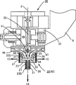
- FIG. 2 is a left side sectional view showing a jet nozzle and a jet nozzle in FIG. 1. It is a left view which shows the jet nozzle attachment / detachment apparatus of the automatic wire insertion apparatus of this invention. It is the perspective view seen from the back side of the main body which shows the jet nozzle attachment / detachment apparatus in FIG. It is a perspective view which shows the jet nozzle attachment / detachment apparatus with which the division
- the automatic wire insertion device of the present invention will be described with reference to FIGS.
- the jet nozzle attaching / detaching device is omitted from the automatic wire inserting device in FIG.
- the main body 10 of the automatic wire insertion device 1 is provided on a machining head that moves up and down.
- a jet nozzle attaching / detaching device 90 for attaching / detaching the jet nozzle 20 to / from the jet nozzle 46 is provided in the main body 10.
- An upper guide assembly 30 is fixed to the lower end of the main body 10. The height of the upper guide assembly 30 can be adjusted by moving the processing head up and down and moving the main body 10 up and down.
- the upper guide assembly 30 is provided with a jet nozzle 46 at its lower end that forms a water column coaxially with the feeding direction of the wire electrode 2.
- the machining gap formed between the wire electrode 2 and the workpiece 3 is surrounded by this water column during machining.
- the opening of the jet nozzle 46 is directed to the workpiece 3.
- the wire electrode 2 is fed out from the wire bobbin 44 by the tension roller 42.
- the tension roller 42 feeds the wire electrode 2 while applying a required tension to the wire electrode 2 in cooperation with the winding roller 56 during processing.
- the wire electrode 2 is inserted into the upper wire guide and the start hole provided in the upper guide assembly 30 by the automatic wire insertion device 1.
- the wire electrode 2 inserted into the start hole is guided to a pipe jet type conveying device 54 by a direction changing pulley 52 through a lower wire guide (not shown) provided in the lower guide assembly 50.
- the conveyance device 54 conveys the wire electrode 2 to the take-up roller 56 by the water flow in the pipe.
- the winding roller 56 includes a driving roller and a capstan.
- a cutting roller having a rotating cutting blade is provided downstream of the winding roller 56.
- the used wire electrode 2 is shredded into small pieces by a cutting roller and discharged to the bucket 58.
- the automatic wire insertion device 1 includes a guide pipe 12, a jet supply unit 14 that supplies a jet to the guide pipe 12, a delivery roller 16, a cutter 18, and a jet nozzle 20. Further, the automatic wire insertion device 1 includes an elevating device that moves the guide pipe 12 up and down in the direction in which the wire electrode 2 is sent out.
- the cutter 18 can be replaced with an energizing / cutting device that locally supplies a large current to the wire electrode 2 and cuts it.
- the automatic wire insertion device 1 can be provided with an annealing device (not shown) for annealing the wire electrode 2.
- the annealed wire electrode 2 is imparted with straightness and becomes difficult to buckle.
- the opening of the guide pipe 12 can be lowered to the position just above the upper wire guide by the lifting device.
- the guide pipe 12 guides the wire electrode 2 to the upper wire guide so that the wire electrode 2 is not buckled by the jet supplied from the jet supply unit 14, and the wire electrode 2 is inserted into the upper wire guide.
- the opening of the guide pipe 12 is positioned higher than the cutter 18.
- the automatic wire insertion device 1 of the present invention includes a jet nozzle 20 attached to the jet nozzle 46 so as to close the opening of the jet nozzle 46.
- the wire electrode 2 is guided to the lower wire guide by the jet supplied from the jet nozzle 20.
- the guide assembly 30 is fixed to the upper arm 6 provided on the lower end side of the main body 10 of the automatic wire insertion device 1.
- the upper guide assembly 30 includes a flat plate-shaped upper contact 32, an upper wire guide 31, a jet nozzle 46, and a housing 33.
- the contact 32 is made of cemented carbide (tungsten carbide) and supplies power to the wire electrode 2.
- the contact 32 is slidable horizontally so that the guide pipe 12 can be lowered to just above the upper wire guide 31.
- the upper wire guide 31 is a partially round diamond die and positions the wire electrode 2. Round dies have relatively high positioning accuracy, and are particularly excellent in taper machining.
- the upper and lower wire guides are provided as close as possible to the workpiece 3 in order to improve positioning accuracy and secure a larger taper angle.
- the opening of the jet nozzle 46 is downward.
- the jet nozzle 46 is fixed to the lower end of the housing 33 by screwing.
- a chamber 47 is formed by the jet nozzle 46 and the housing 33.
- the jet nozzle 20 includes a small-diameter jet nozzle body 21 and a large-diameter outer frame 23.
- a chamber 22 is formed by the jet nozzle 20 and the jet nozzle 46.
- the jet direction 1A is coaxial with the delivery direction of the wire electrode 2 and is generally downward.
- annular protrusion 48 is formed over the vertical outer peripheral surface 44 of the jet nozzle 46.
- An annular groove 25 complementary to the annular protrusion 48 in the shape is formed in the vertical inner peripheral surface 24 of the outer frame 23.
- the jet nozzle 20 is coupled to the jet nozzle 46 by fitting the annular protrusion 48 into the annular groove 25.
- the vertical inner peripheral surface 24 of the outer frame 23 and the vertical outer peripheral surface 44 of the jet nozzle 46 are in close contact with each other.
- An annular protrusion may be formed on the vertical inner peripheral surface 24 of the outer frame 23, and an annular groove may be formed on the vertical outer peripheral surface 44 of the jet nozzle 46.
- a play (clearance) is provided between the annular protrusion 48 and the annular groove 25.
- the annular protrusion 48 is triangular or trapezoidal in cross section, and has an inclined surface, and the cross section in which the annular groove 25 is fitted to the annular protrusion 48 is triangular or trapezoidal.
- the shape has an inclined surface. For this reason, the annular groove 25 is guided and fitted to the inclined surface of the annular protrusion 48, so that even if there is no clearance between the annular protrusion 48 and the annular groove 25, the positional deviation between the jet nozzle 20 and the jet nozzle 46 is shifted. Absorbed.
- the high-pressure water is supplied to the chamber 22 along the direction 1B in the chamber 47 and further supplied to the jet nozzle body 21.
- the direction 1B in which the high-pressure water is supplied is the same downward direction as the jet direction 1A.
- the annular groove 25 is pressed downward against the annular protrusion 28 by the downward force of the high pressure water. In this way, the jet nozzle 20 is reliably coupled to the jet nozzle 46 by the high-pressure water, and the opening of the jet nozzle 46 is reliably sealed.
- the jet nozzle 20 is equally divided into right and left as viewed from the front along the jet direction 1A.
- the right half when viewed from the front of the jet nozzle 20 is the first divided nozzle 91, and the left half is the second divided nozzle 92.
- the first divided nozzle 91 includes a radial direction 1C of the jet nozzle 20 on an upper divided surface 23U on the upper side of the outer frame corresponding to a portion forming the chamber 22 of the jet nozzle 20 of the outer frame 23 constituting the housing of the jet nozzle 20.
- the projections 26 or the trough grooves 27 are provided without interruption in parallel to the direction 1A, in other words, along the jet direction 1A.
- the second divided nozzle includes an angle projection 26 or a valley groove so as to face the angle projection 26 or the valley groove 27 provided on the first division nozzle 91 on the upper division surface 23U on the upper side of the outer frame.
- a trough-shaped groove 27 or a mountain-shaped protrusion 28 having a shape to be fitted to the groove 27 is provided without interruption.
- each of the divided nozzles 91 and 92 has two divided surfaces formed on each outer frame 23, and one of the divided nozzles 91 and 92 has an outer surface centered on an axis coaxial with the jet direction 1A.
- a chevron 26 is formed in the clockwise direction along the frame 23, and a trough groove 27 is formed in the counterclockwise direction along the outer frame 23 on the other split surface.
- the internal pressure of the high-pressure water is radially applied to the radial direction 1 ⁇ / b> C of the jet nozzle 20, so that the chevron protrusions 26 are pressed against the trough grooves 27 in the radial direction. 26 and the trough groove 27 are engaged with each other, and a slight gap between the chevron 26 and the trough groove 27 is closed.
- the positions of the divided nozzle 91 and the divided nozzle 92 do not shift, so that separation is difficult, and the liquid can be sealed between the divided surfaces with the internal pressure of the high-pressure water for more reliable sealing.
- the chevron 26 has a triangular or trapezoidal cross section and an inclined surface.
- the trough groove 27 has a shape that fits into the chevron 26.
- the chevron 26 and the trough groove 27 are in a positional relationship that faces each other so that the divided nozzles 91 and 92 are fitted to each other on the divided surfaces. Since the valley groove 27 is guided and fitted to the inclined surface of the chevron 26, when the divided nozzles 91 and 92 and the jet nozzle 46 are combined, the first divided nozzle 91 and the second divided nozzle 92 Misalignment is absorbed. Therefore, the uniting of the divided nozzles 91 and 92 and the coupling of the divided nozzles 91 and 92 and the jet nozzle 46 are performed smoothly at the same time, so that the jet nozzle 20 can be completely attached to the jet nozzle 46.
- the jet nozzle 20 uses the pressure of high-pressure water acting in a direction to separate the first divided nozzle 91, the second divided nozzle 92, and the jet nozzle 46 of the jet nozzle 20 from each other. 20 and the jet nozzle 46, and the joint portion is sealed. For this reason, the jet nozzle 20 has both high connectivity, liquid tightness, and ease of coupling with a relatively simple configuration.
- the first divided nozzle 91 has a radial direction of the jet nozzle 20 on a lower divided surface 23 ⁇ / b> B on the lower side of the outer frame corresponding to a portion where the jet nozzle body 21 of the outer frame 23 is formed.
- a chevron 26 or a trough 27 is provided without interruption in a direction perpendicular to 1C.
- the second divided nozzle 92 has a valley-shaped groove 27 or a groove shaped to fit with a mountain-shaped projection 26 or a valley-shaped groove 27 provided on the first divided nozzle 91 on the lower divided surface 23B on the lower side of the outer frame.
- the chevron 28 is provided without interruption.
- the chevron 26 and the trough groove 27 are fitted to each other on the upper divided surface 23U on the upper side of the outer frame, so that high connectivity and coupling can be achieved.
- the jet nozzle 20 shown in FIG. 2 is configured so that the chevron 26 and the trough groove 27 are fitted to each other on the lower divided surface 23B on the lower side of the outer frame.
- the attachment / detachment device 7 includes a first finger 61, a second finger 62, an opening / closing device 70, and a moving device 80.
- the first finger 61 supports the first divided nozzle 91
- the second finger 62 supports the second divided nozzle 92.
- the opening / closing device 70 opens and closes the fingers 61 and 62.
- the fingers 61 and 62 and the opening / closing device 70 are provided integrally, and constitute a main unit 90 including the jet nozzle 20.
- the constituent members of the opening / closing device 70 are visible.
- a cover that covers the constituent members of the opening / closing device 70 is provided, and the constituent members are fixed to the cover. It is made not to fall off.
- the moving device 80 swings the jet nozzle 20 together with the opening / closing device 70 in the rotational direction 1D between the retracted position 10A and the mounting position 10B.
- the retreat position 10A is the back of the main body 10 of the automatic wire insertion device 1 as shown in FIG.
- the mounting position 10B is directly under the opening of the jet nozzle 46, as shown in FIG. Since the jet nozzle 20 is moved from the retracted position 10A to the mounting position 10B in one stroke, the time required for the wire insertion process is shortened.
- the moving device 80 includes a swing bracket 81, a driving device 82, and a link mechanism 83.
- the swing bracket 81 is attached to the main body 10.
- the driving device 82 swings and reciprocates in the rotational direction 1D by swinging the main body unit 90 like a pendulum around the horizontal X axis with the mounting position 80X of the swing blanket 81 as a fulcrum.
- the link mechanism 83 converts the linear reciprocating motion of the driving device 82 into the rotational reciprocating motion of the main unit 90 and transmits it.
- the drive device 82 is a cylinder device such as an air cylinder or a hydraulic cylinder that operates with compressed air supplied from an air source such as a compressor (not shown) or pressurized oil supplied from an oil tank.
- the drive device 82 is accommodated so that the cylinder cylinder is vertically arranged in a recessed groove portion 10C provided on the back of the main body 10 of the automatic wire insertion device 1 shown in FIG.
- the retracting position 10A of the main body unit 90 is provided at the back of the main body 10 of the automatic wire insertion device 1, in the movement method using a combination of linear movements, a plurality of strokes are performed to move the jet nozzle from the retracting position 10A to the mounting position 10B. It is necessary to move via. Since the moving device 80 shown in FIG. 4 is configured to be able to swing the jet nozzle 20, the jet nozzle 20 can be positioned from the retracted position 10 ⁇ / b> A to the mounting position 10 ⁇ / b> B in one stroke by following the trajectory of the turning movement. it can. Therefore, the main body unit 90 can be accommodated in a position where it does not become an obstacle to work or processing without giving a significant loss to the time required for automatic wire insertion.
- the position where the jet nozzle 20 is attached is the front side (front part) of the main body unit 90 and is the tip portion of the pair of fingers 61 and 62. And let the direction of a front-end
- the direction perpendicular to the central axis 90C along the jet direction 1A is defined as the vertical direction
- the direction perpendicular to the central axis 90C and perpendicular to the vertical axis is defined as the horizontal direction
- the direction 1E to leave is the outside.
- a plane parallel to the central axis 90C and perpendicular to the longitudinal axis is defined as a mounting plane
- a plane parallel to the mounting plane and positioned in the jet direction 1A is a lower surface (back surface), and is opposite to the jet direction 1A.
- the located surface is called the upper surface (surface).
- the moving device 80 swings the main body unit 90 and arranges the jet nozzle 20 at the attachment position 10A in one stroke.
- the jet nozzle 20 is mounted with an inclination with respect to the mounting plane of the main unit 90, as shown in FIG. Therefore, although the longitudinal axis of the main unit 90 is not exactly parallel to the jet direction 1A, the longitudinal axis and the jet direction 1A are considered to be parallel.
- the first finger 61 and the second finger 62 are opened and closed by a so-called double-open double-close method in which the first finger 61 and the second finger 62 move in directions opposite to each other in a direction orthogonal to the divided surfaces of the divided nozzles 91 and 92 of the jet nozzle 20. Specifically, the first finger 61 and the second finger 62 reciprocate around the same fulcrum 65 in a direction opposite to each other around one longitudinal axis parallel to the jet direction 1A.
- the rear end portions of the first finger 61 and the second finger 62 are perpendicular to the central axis 90C passing through the rear end portion from the front end portion of the main body unit 90 including the opening / closing device 70 and perpendicular to the longitudinal axis.
- notches 63 and 64 having a semicircular head shape opening in the direction 1E away from the central axis 90C are formed. Therefore, the notch 63 provided in the first finger 61 and the notch 64 provided in the second finger 62 open in opposite directions.
- the rear ends of the fingers 61 and 62 are formed in a bowl shape by the notches 63 and 64.
- the opening / closing device 70 opens and closes by moving the first finger 61 and the second finger 62 in directions opposite to each other in a direction orthogonal to the divided surfaces of the divided nozzles 91 and 92 of the jet nozzle 20.
- the opening / closing device 70 opens and closes the pair of fingers 61, 62 at the mounting position 10B to merge or divide the first divided nozzle 91 and the second divided nozzle 92, and at the same time, the first divided nozzle 91 and the second divided nozzle 91
- the divided nozzle 92 and the jet nozzle 46 are combined or separated.
- the opening / closing device 70 is a direction perpendicular to the divided surfaces of the divided nozzles 91 and 92 around one axis in the vertical direction around the same fulcrum 65 for the first finger 61 and the second finger 62. Are opened and closed by reciprocating in the opposite directions in the turning direction 1F on the mounting plane.
- the double-open and double-closed configuration in which the pair of fingers 61 and 62 in the attachment / detachment device 7 swings and reciprocates in opposite directions around the same fulcrum 65 opens and closes at the mounting position 10B. It is possible to combine or separate the first divided nozzle 91, the second divided nozzle 92, and the jet nozzle 46 while combining or dividing the divided nozzle 92.
- the automatic wire insertion device 1 shown in the figure can attach and detach the jet nozzle 20 and the jet nozzle 46 in one operation, reducing the number of steps in the attachment and detachment of the jet nozzle 20 and reducing the time required for automatic wire insertion. It is effective in that it can be shortened. Further, the configuration of the main unit 90 shown in FIGS. 5 and 6 is important in that the jet nozzle 20 can be swung between the retracted position 10A and the mounting position 10B as a result.
- the opening / closing device 70 includes a driving device 78 that is a cylinder device that linearly reciprocates in a single longitudinal direction 90Y parallel to the central axis 90C of the main unit 90, and a longitudinal one so as to open and close the pair of fingers 61 and 62.
- a pair of arms 71 and 72 that simultaneously rotate in opposite directions in the turning direction 1G on the mounting plane around the axial direction, and a linear reciprocating motion in the one-axis direction 90Y of the drive device 78 rotate the arms 771 and 72.
- a conversion joint 73 that converts the rotational reciprocating motion in the direction 1G.
- the driving device 78 is an air air cylinder that operates with compressed air supplied from an air source (not shown).
- the air cylinder is advantageous in that it can provide a necessary and sufficient force in the direction in which the divided nozzles 91 and 92 of the jet nozzle 20 are combined against the pressure of the high-pressure water compared to the size.
- the arms 71 and 72 are reciprocally moved around one axis in the vertical direction in the turning direction 1G opposite to the turning direction 1F on the same mounting plane as the turning direction 1F of the first finger 61.
- the first arm 61 on the right side from the front for turning the first finger 61 in the turning direction 1F and the same mounting plane as the turning direction 1F of the second finger 62 are opposite to the turning direction 1F.
- Each of the arms 71 and 72 has a roller-like cylindrical member 74 that holds the united jet nozzle 20.
- the cylindrical member 74 is formed along the edges of the semicircular cutouts 63 and 64 formed in the rear end portions of the pair of fingers 61 and 62, respectively. Move while rotating around the central axis of the cylinder.
- the diameter of the cylindrical member 74 is smaller than the diameter of the semicircular arc portions of the notches 63 and 64.
- the cylinder internal pressure of the cylinder device of the drive device 78 is changed so that the conversion joint 73 is in a position in front of the main body unit 90. Therefore, the coupling of the jet nozzle 20 is held by the force of compressed air against the force of high-pressure water that attempts to separate the jet nozzle 20.
- the cylindrical member 74 attached to the distal ends of the arms 71 and 72 is in a substantially locked state against the force in the direction in which the fingers open when the jet nozzle 20 is united, and the cylinder device is compressed air. It has the effect
- the cylindrical member 74 When the jet nozzle 20 is united, the cylindrical member 74 is stopped so as to push forward at the edges of the straight portions of the notches 63 and 64, and is locked in the direction in which the pair of fingers 61 and 62 are about to open. However, since the cylindrical member 74 is configured to rotate around the central axis of the cylinder, the conversion joint 73 linearly moves rearward and pulls the arms 71 and 72 so as to turn in a direction approaching the central axis 90C. When the cylinder member 74 is used, the cylindrical member 74 rotates and easily moves out of the straight portions of the notches 63 and 64. Therefore, the cylinder device can easily retract the piston, and the jet nozzle 20 can be divided.
- the stopping position of the cylindrical member 74 when the jet nozzle 20 is united greatly exceeds the position perpendicular to the edges of the straight portions of the notches 63 and 64 so that the arms 71 and 72 are separated from the central axis 90C. If it extends too far in the separating direction 1E, when the conversion joint 73 moves rearward, the arms 71, 72 do not pivot in a direction approaching the central axis 90C in an attempt to pivot in a direction separating in the direction 1E away from the central axis 90C. Therefore, as shown in FIGS. 5 and 6, the stop position of the cylindrical member 74 when the jet nozzle 20 is combined is configured so that the arms 71 and 72 always return in the direction approaching the central axis 90 ⁇ / b> C. However, it is not difficult to design.
- the jet nozzle 20 is located at the retracted position 10A as shown in FIG.
- the pair of fingers 61 and 62 are closed to prevent the jet nozzle 20 from being damaged.
- the pair of fingers 61 and 62 may be opened in advance.
- a control device (not shown) is started based on an input from a button or switch on the control panel in the numerical control device or a touch sensor on the screen of the liquid crystal display or a command signal according to the decoded NC program.
- the control device is a sequencer that operates the automatic wire insertion device in a prescribed order.
- the cutter 18 is actuated to cut the wire electrode 2 so that the tips of the wire electrode 2 are aligned.
- the winding electrode of the discharge device 56 is driven to discharge the remaining wire electrode 2 to the bucket 58.
- the cut piece is discharged out of the apparatus by a tip processing device (not shown).
- the drive unit 82 of the moving device 80 of the attachment / detachment device 7 is actuated by a signal from the control device to push down the main body unit 90 forward.
- the drive device 78 of the opening / closing device 70 is operated while the main body unit 90 is oscillating.
- the fingers 61 and 62 are opened to divide the jet nozzle 20.
- the body unit 90 of the detachable device 7 that has been pushed down is supported by a swing blanket 81 that rotates in the rotational direction 1D in a pendulum manner around the X-axis direction around the fulcrum 81X. Then, it swings in one stroke from the retracted position 10A to the mounting position 10B just below the opening of the jet nozzle 46 in the rotational direction 1D.
- the drive device 78 of the opening / closing device 70 in the main unit 90 is operated to advance the conversion joint 73.
- the conversion joint 73 moves to the front of the main unit 90, the arms 71 and 72 turn in the opposite directions in the turning direction 1G toward the outside around the vertical axis.
- a part of the side surface of the cylindrical member 74 moves in contact with the edges of the notches 63 and 64 formed at the rear end portions of the fingers 61 and 62 while rotating to move the fingers 61 and 62 forward of the main body unit 90. Extrude into. Since the fingers 61 and 62 pushed out forward are supported by the fulcrum 65, the turning direction 1F opposite to the turning direction 1G on the same mounting plane as the turning direction 1G of the arms 71 and 72 around the fulcrum 65 is provided. And the split nozzles 91 and 92 attached so as to face the tip portion are combined, and at the same time, the split nozzles 91 and 92 and the jet nozzle 46 are combined.
- annular protrusion 48 having an inclined surface is provided on the jet nozzle 46, and a shape corresponding to the annular protrusion 48 is formed on the upper inner peripheral surface 24 of the outer frame 23 of each divided nozzle 91, 92 constituting the housing of the jet nozzle 20.
- the annular groove 25 is formed at a position facing the annular protrusion 48. Therefore, when the jet nozzle 20 is united at the mounting position 10A, the annular groove 25 fits along the inclined surface of the annular projection 48, and the misalignment between the divided nozzles 91 and 92 and the jet nozzle 46 is absorbed, which is a failure.
- the divided nozzles 91 and 92 are surely combined with each other, and at the same time, the divided nozzles 91 and 92 are coupled to the jet nozzle 46.
- the jet nozzle 20 is orthogonal to the radial direction 1C of the jet nozzle 20 at least on the upper divided surface 23U on the upper side of the outer frame corresponding to the portion forming the chamber 22 of the outer frame 23 of each divided nozzle 91, 92.
- a trough-shaped protrusion 26 and a trough-shaped groove 27 having a shape that fits the chevron 26 are opposed to each other so as to be fitted to each other. Therefore, when the jet nozzle 20 is united at the mounting position 10A, the valley-shaped groove 27 is guided and fitted to the inclined surface of the chevron projection 26 so that the divided surfaces of the first divided nozzle 91 and the second divided nozzle 92 are aligned. It is precisely aligned and the dividing surface is sealed.
- the jet nozzle 20 is swung in one stroke from the retracted position 10A to the mounting position 10B and the first divided nozzle 91 and the second divided nozzle at the mounting position 10B. And the jet nozzle 20 is attached to the jet nozzle 46 in only two steps, including the step of attaching the jet nozzle 20 to the jet nozzle 46.
- the jet nozzle 20 is attached to the jet nozzle 46 by simply opening and closing the pair of fingers 61 and 62. Therefore, the automatic wire insertion device of the embodiment has a relatively simple operation and a small number of processes.
- high-pressure water is supplied to the jet nozzle 20 along the direction 1B in which high-pressure water is supplied from the jet nozzle 46, as shown in FIG.
- the high-pressure water supplied to the chamber 22 is jetted coaxially with the direction in which the wire electrode 2 is sent out from the jet nozzle body 21 in the jet direction 1A.
- a jet is supplied to the guide pipe 12 from the jet supply unit 14 shown in FIG. Further, the upper energization body 32 shown in FIG. 2 is retracted to a position where it does not get in the way so as to be separated from the delivery path of the wire electrode 2.
- the guide pipe 12 is lowered until the tip of the guide pipe 12 passes over the upper electric conductor 32 and reaches a height position just above the upper wire guide 31, and the tension roller 42, which also serves as a feed roller, and the wire electrode 2 feed out.
- the wire electrode 2 in the guide pipe 12 is sent out in cooperation with the sending roller 16 that sends it out without departing from the path.
- the tip of the wire electrode 2 guided by the guide pipe 12 and passed through the upper wire guide 31 is surrounded by the high-pressure water supplied along the direction 1B in which the high-pressure water is supplied. While being guided, the wire electrode is fed into the jet nozzle body 21 while maintaining the feeding path. Then, it is propelled while being restrained by the jet and led to the entrance of the start hole.
- the tip of the wire electrode 2 that has been inserted into the start hole and passed through the lower wire guide is captured and connected to the winding roller of the discharge device 56 shown in FIG.
- the control device stops feeding the wire electrode 2. Further, the control device stops the supply of the jet from the jet supply unit 14 shown in FIG. 1, raises the guide pipe 12 to the initial position where the tip of the guide pipe 12 is located above the cutter 18, and the jet nozzle 46. Stop the supply of high-pressure water from
- the drive device 78 of the opening / closing device 70 in the main unit 90 is operated to retract the conversion joint 73 to the initial position.
- the arms 71 and 72 turn in opposite directions in the turning direction 1G toward the inside approaching the central axis 90C.
- a part of the side surface of the cylindrical member 74 moves while rotating in contact with the edges of the notches 63 and 64 formed at the rear end portions of the fingers 61 and 62, respectively.
- the fingers 61 and 62 are pulled down to the rear of the main unit 90.
- each of the divided nozzles 91 and 92 of the jet nozzle 20 mounted so as to be pivoted in the opposite directions around the vertical axis and released to be opposed to the tip portion is divided.
- the cylinder device of the driving device 82 of the moving device 80 is operated to pull up the main unit 90 backward.
- the main body unit 90 pulled up rearward is supported by a swing blanket 81 that rotates in a rotational direction 1D in a pendulum-like manner around the X axis direction around a fulcrum 81X.
- the rocking is performed in one stroke.
- the wire electrode 2 is already connected between the upper and lower wire guides since the wire electrode 2 is already connected when the jet nozzle 20 is separated from the jet nozzle 46, removed and swung to be accommodated in the initial retracted position 10A. It is in a state of being stretched around. At this time, since the jet nozzle 20 is vertically divided from the center to the left and right, and the pair of fingers 61 and 62 move in opposite directions to open and close, each split nozzle 91 and 92 It can come out without being caught by the stretched wire electrode 2 and can be detached from the mounting position 10B.
- the automatic wire insertion device of the present invention is not limited to the configuration of the automatic wire insertion device specifically illustrated and described, but deviates from the technical idea of the present invention as some examples have already been given. Modifications can be made without departing from the scope.
Landscapes
- Chemical & Material Sciences (AREA)
- Chemical Kinetics & Catalysis (AREA)
- Electrochemistry (AREA)
- Engineering & Computer Science (AREA)
- Mechanical Engineering (AREA)
- Electrical Discharge Machining, Electrochemical Machining, And Combined Machining (AREA)
- Nonwoven Fabrics (AREA)
Abstract
自動ワイヤ挿通装置は第1および第2の分割ノズル91、92から成るジェットノズル20を含む。ジェットノズル20は噴流ノズル46に装着可能である。自動ワイヤ挿通装置は、更に、第1の分割ノズル91を支持する第1のフィンガ61と、第2の分割ノズル92を支持する第2のフィンガ62と、第1および第2のフィンガ61、62を開閉して第1および第2の分割ノズル91、92を合体または分割させると同時にジェットノズル20と噴流ノズル46とを結合または分離させる開閉装置70を含む。ジェットノズル20の内周面24に環状溝25が形成され、環状溝25に嵌合する環状突起48が噴流ノズル46の外周面に形成される。第1および第2の分割ノズル91、92はそれぞれの分割面(23U、23B)を有する。谷形溝が第1の分割面に形成され、谷形溝と嵌合する山形突起が第2の分割面に形成されている。
Description
本発明は、一対のワイヤガイド間を走行するワイヤ電極とワーク間に形成される加工間隙に放電を発生させてワークを加工するワイヤ放電加工装置に関する。特に、本発明は自動的にワイヤ電極を一対のワイヤガイド間に張架するワイヤ放電加工装置の自動ワイヤ挿通装置に関する。
数値制御装置を有するワイヤ放電加工装置は、自動的にワイヤ電極を上ワイヤガイド、開始穴、下ワイヤガイドに順に挿通させ、巻取りローラに捕捉させる装置、いわゆる自動ワイヤ挿通装置(Automatic Wire Threader)を備えている。開始穴は、放電加工に先立ってワーク中に形成された1mm程度の穴である。典型的には、ワイヤ電極の径は0.20mmであり、ワイヤガイドはφ0.21mmの挿通孔を有する。
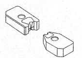
図7は「丸ダイス」と呼ばれるよく知られた高精度なワイヤガイドを示している。が各ワイヤガイドはガイド組体に収容されている。各ガイド組体は加工間隙に向けて加工液を供給する噴流ノズルを備えている。噴流ノズルは典型的にはφ6mm程度の開口を有する。ワイヤガイドは不可避的に噴流ノズルの開口よりもワークから遠くに位置している。
一般に、自動ワイヤ挿通装置は、ワイヤ電極の送出し方向に同軸に加工液ジェット(以下「ジェット」)を形成するジェットノズルを備えている。ジェットはワイヤ電極を拘束しながら下ワイヤガイドまで推進する。
特許文献1はジェットノズルが噴流ノズルと同軸にガイド組体中に設けられた自動ワイヤ挿通装置を開示している。ジェットノズルは典型的にはφ1.5mmの開口を有する。上ワイヤガイドを通過したワイヤ電極をジェットによって案内するため、ジェットノズルの開口は上ワイヤガイドの直下に配置されている。したがって、ジェットノズルの開口から下ワイヤガイドまでに相当の距離がある。そのため、ジェットがワイヤ電極を拘束すると共に推進する力が小さくなり、ジェット中に乱流が生じやすくなる。その結果、ジェットがワイヤ電極を下ワイヤガイドの孔に挿通させる確率が低くなる。
特に、径が小さく剛性が極めて低いワイヤ電極が使用される場合、ワイヤ電極をジェットのみで案内することがより困難になる。また、開始穴がジェットの径より小さい場合、ジェットは開始穴の入口で乱れてワイヤ電極の先端が開始穴に正確に導かれないことが多い。
また、ワークの形状に因り上ガイド組体を開始穴に接近させることができない場合、ジェットノズルから開始穴までの距離が長すぎてワイヤ電極を開始穴に挿通させることが極めて困難である。
特許文献2は、上ワイヤガイドから下方に延長されたジェットノズルを備えた自動ワイヤ挿通装置を開示している。ジェットノズルの開口は噴流ノズルの開口に可能な限り近く位置している。ジェットノズルから開始穴までの距離が短く自動挿通の成功率が向上している。
しかしながら、ジェットノズルの開口は噴流ノズルよりもずっと小さい径を有するため、延長されたジェットノズルは、上下ワイヤガイド間でワイヤ電極が傾く角度、すなわちテーパ角度を大きく制限してしまう。
特許文献3および4は、上下に移動可能なジェットノズルを備えた自動ワイヤ挿通装置を開示している。自動ワイヤ挿通に際して、ワイヤ挿通の成功率を高めるためジェットノズルの開口が噴流ノズルの開口の近くまで降下させられる。加工に際しては、ジェットノズルが大きくテーパ角度を制限しないようにジェットノズルの開口が上ワイヤガイドの直下へ上昇させられる。しかしながら、ジェットノズルの開口は噴流ノズルよりもずっと小さい径を有するため、ジェットノズルは依然としてテーパ角度を制限してしまう。
特許文献5は、ワイヤ電極が通る上下移動可能なガイドパイプを備えた自動ワイヤ挿通装置を開示している。ワイヤ電極はガイドパイプの中に挿入され、ガイドパイプに供給されるジェットによって、ワイヤ電極は下ワイヤガイドまで案内される。典型的なガイドパイプは2mmの外径と1mmの内径を有する。
特許文献5は、ガイドパイプを通すために分割可能なワイヤガイドを開示している。図8は「割りダイス」と呼ばれる典型的な分割可能なワイヤガイドを示している。上ワイヤガイドが割りダイスであれば、ガイドパイプの開口を開始穴の入口に位置させることが可能になる。その結果、自動ワイヤ挿通の成功率が高まる。
しかし、割りダイスは耐久性が低く磨耗しやすいと見なされている。また、割りダイスは、丸ダイスに較べて、位置決め誤差が高いと見なされている。特に、割りダイスは、丸ダイスに較べて、上下ワイヤガイド間で傾斜させられたワイヤ電極を使用する加工、いわゆる「テーパ加工」において精度的に劣ると見なされている。
特許文献6、7および8は、「サブノズル」と呼ばれるジェットノズルを備えた自動ワイヤ挿通装置を開示している。サブノズルは、ワイヤ挿通プロセス中に限って、噴流ノズルの開口を閉塞するように噴流ノズルに装着される。サブノズルは通常水平に分割可能であるので、ワイヤ電極が上下ワイヤガイド間に張架された後にサブノズルは噴流ノズルから取り外し可能である。
このような自動ワイヤ挿通装置では、テーパ角度を制限するジェットノズルが上ガイド組体内に存在しない。サブノズルの開口を開始穴の入口の直近に位置させることが可能であるので、ワイヤ挿通の成功率が高い。サブノズルは、ガイドパイプと異なり、割りダイスを必要としない。加えて、ワークの形状に因り上ガイド組体を開始穴に接近させることができない場合でも、噴流ノズルよりも外径が小さいサブノズルを容易に開始穴に近接させることができる。
「サブノズル」式の自動ワイヤ挿通装置は、ワイヤ挿通に際して自動的にジェットノズルを噴流ノズルに取り付け/取り外しするためのジェットノズル着脱装置を必要とする。ジェットノズル着脱装置は、分割ノズルを正確に合体させ噴流ノズルに強固に液密に結合させなければならない。また、高圧水が噴流ノズルを介して小径のジェットノズルに供給されるため、ジェットノズルと噴流ノズルとの結合部分にかかる負荷が大きい。
本発明は、比較的簡単な構成と動作で、ジェットノズルを噴流ノズルに確実に液密に自動的に装着することができる自動ワイヤ挿通装置を提供することを主たる目的とする。本発明の自動ワイヤ挿通装置のいくつかの優れる点は、発明を実施するための最良の形態の説明に沿って詳細に記述される。
本発明は、第1および第2の分割ノズル(91、92)から成るジェットノズル(20)が噴流ノズル(46)の開口を閉塞するように噴流ノズルに装着され、ジェットノズルが形成するジェットによってワイヤ電極が案内されるワイヤ放電加工装置の自動ワイヤ挿通装置(1)に関する。自動ワイヤ挿通装置(1)は、第1の分割ノズル(91)を支持する第1のフィンガ(61)と、第2の分割ノズル(92)を支持する第2のフィンガ(62)と、第1および第2のフィンガ(61、62)を開閉して第1および第2の分割ノズル(91、92)を合体または分割させると同時にジェットノズル(20)と噴流ノズル(46)とを結合または分離させる開閉装置(70)とによって特徴付けられる。更に、自動ワイヤ挿通装置(1)は、環状溝(25)がジェットノズルの内周面(24)と噴流ノズルの外周面(44)のうち一方に形成され、環状溝(25)に嵌合する環状突起(48)がジェットノズルの内周面(24)と噴流ノズルの外周面(44)のうち他方に形成されていることを特徴とする。
好ましくは、第1の分割ノズル(91)は第1の分割面(23U、23B)を有し、第2の分割ノズル(92)は第2の分割面(23U、23B)を有し、谷形溝(27)が第1の分割面に形成され、谷形溝と嵌合する山形突起(26)が第2の分割面に形成されている。
好ましくは、自動ワイヤ挿通装置は、ジェットノズルを自動ワイヤ挿通装置の後背と噴流ノズルの開口の直下との間で揺動させる移動装置を更に含む。
噴流ノズルの下側にジェットノズルが装着されるので、ジェットノズルに高圧水の内圧による噴流ノズルからジェットノズルが外れる方向の下向きの力が加わる。また、内径の大きい噴流ノズルから内径の小さいジェットノズルに高圧水が供給されるから、ジェットノズルの中に導入された高圧水はジェットノズルの径方向にもジェットノズルを内側から拡大するように放射状に負荷を与える。
本発明の自動ワイヤ挿通装置はジェットノズルの径方向に環状突起を環状溝に嵌合させるので、高圧水の圧力によって環状溝が嵌合突起に下向きに押し付けられて密着する。その結果、ジェットノズルが噴流ノズルに固定されるので、ジェットノズルが噴流ノズルから開離しにくく、高圧水が漏出しない。
したがって、ジェットノズルと噴流ノズルの結合部分を環状突起と環状溝だけで構成することができ、結合部分の構造が簡単で耐久力を有し、ジェットノズルと噴流ノズルが破損するおそれがなく、安全性が向上する。また、高圧水の圧力で結合部分をシールするので、シール部材のような構成部品が必ずしも要求されず、ジェットノズルの製作コストが低減される。そして、結合部分が比較的簡単な構成で経年劣化しやすい構成部品が少ないので、結合部分の耐久性や液密性が直ちに失われることがなく、安全性が向上する。
また、本発明の自動ワイヤ挿通装置は、高圧水の圧力で環状突起と環状溝との隙間を密着させてシールする構成であるから、環状突起と環状溝の間に遊びを持たせることができ、ジェットノズルの各分割ノズルと噴流ノズルとの間に位置ずれがあっても、ジェットノズルが噴流ノズルに結合できなくなるおそれが小さい。そのため、ジェットノズルと噴流ノズルに必要以上に高い精度が要求されない。
そして、高圧水がジェットノズルに供給される下向きの方向に直交する水平面の方向で環状突起と環状溝を嵌め合わせるので、各分割ノズルを分割面に直交する方向から噴流ノズルに結合させることができ、各分割ノズルの合体と同時に噴流ノズルに結合することができる。嵌合で結合する方法は、係合、螺合、固定部材で結合する方法に比べて自動ワイヤ挿通装置と制御装置の構成をより簡単にすることができ、製造コストが低減される。また、ジェットノズルを着脱する動作が比較的簡単で工程数が少なくなるので、ジェットノズルの着脱時間が短くなり、自動ワイヤ挿通に過大な時間が必要とされない。
ジェットノズルの各分割ノズルの分割面に山形突起と山形突起に相対向して嵌合する形状の谷形溝を形成して結合する構成は、山形突起と谷形溝が互いの斜面に案内されて嵌合するので、各分割ノズル間の位置ずれが吸収される。そのため、各分割ノズルの合体と噴流ノズルの結合とを同時に行なってより確実にジェットノズルと噴流ノズルが結合される。その結果、作業の中断がなく、作業性が向上する。また、各分割ノズルを合体するときの位置決め精度に過剰に高い精度が要求されないので、ジェットノズルの製作コストと自動ワイヤ挿通装置の製造コストが低減される。
そして、ジェットノズルの径方向に対して直交する方向に山形突起と谷形溝とを嵌め合わせて分割ノズルを合体させているから、高圧水の内圧がジェットノズルの径方向に放射状にかかることで放射方向に山形突起が谷形溝に押し付けられて山形突起と谷形溝との間の隙間が塞がれる。そのため、簡単な構成でありながら各分割ノズル間からの高圧水の漏出が確実に防止される。
このように、本発明の自動ワイヤ挿通装置によると、ジェットノズルと噴流ノズルを結合する動作が簡単であるので、ジェットノズルの着脱時間を大幅に短縮することができる。また、環状突起と環状溝との間に遊びがあるので、ジェットノズルと噴流ノズルとの結合に失敗することがなく、作業性が向上する。また、結合部分が環状突起と環状溝だけで構成されているので、構成が簡単で耐久性があり、構成部品の破損のおそれがない。その結果、作業効率と安全性が向上する効果を奏する。
また、本発明の自動ワイヤ挿通装置によると、環状突起と環状溝との間に遊びを持たせることができ、噴流ノズルの製作が格別困難になることがない。また、ジェットノズルと噴流ノズルとの結合における構成と動作が簡単であるので、自動ワイヤ挿通装置と制御装置の構成を簡単にできる。また、環状突起と環状溝との間に遊びがあるので、高精度の位置決めができる高品位の光学部品と移動装置が不要である。その結果、自動ワイヤ挿通装置の製造に過大なコストが必要とされない。
自動ワイヤ挿通装置がジェットノズルを自動ワイヤ挿通装置の後背と噴流ノズルの開口の直下との間で揺動させる移動装置を有する場合は、ジェットノズルを1行程で退避位置から装着位置まで移動させることができるので、ジェットノズルを着脱するときの動作が一層簡単で工程数がより少なくなり、ジェットノズルの着脱時間が短く、自動ワイヤ挿通に要する時間をより短縮できる。したがって、作業効率が一層向上する効果を奏する。
開閉装置が一対のフィンガを同一の支点を中心に旋回往復移動させて開閉させる構成である場合は、1回の動作でジェットノズルの各分割ノズルを同時に互いに反対方向に移動させることができるので、比較的簡単な構成で分割ノズルどうしの合体を短時間に円滑に行なうことができる。また、分割ノズルどうしおよび各分割ノズルと噴流ノズルの位置ずれが低減される。したがって、作業効率が一層向上する効果を奏する。
各フィンガの後端部位に頭部半円形状の切欠きが形成され、円筒部材が切欠きの縁に接触して回転しながらフィンガを旋回させるようにアームが旋回する構成である場合は、開閉装置の駆動装置の直線往復運動によってフィンガを同時に互いに反対方向に旋回させて開閉させるようにすることができるとともに、ジェットノズルの合体を保持することができる。そのため、各分割ノズルどうしを押え付けておく開閉装置の駆動装置の駆動力が小さくても各分割ノズルの分離を防止することができ、開閉装置の駆動装置を小型化してジェットノズル着脱装置をコンパクトにし、製造コストが一層低減されるとともに、安全性が向上する効果を奏する。
図1ないし図6を参照して、本発明の自動ワイヤ挿通装置が説明される。図1中の自動ワイヤ挿通装置からジェットノズル着脱装置が省略されている。
自動ワイヤ挿通装置1の本体10は、上下に移動する加工ヘッドに設けられている。図3および4中に示されるように、ジェットノズル20を噴流ノズル46に取り付け/取り外しするジェットノズル着脱装置90は、本体10に設けられている。本体10の下端に上ガイド組体30が固定されている。加工ヘッドを昇降して本体10を上下に移動させることによって、上ガイド組体30の高さを調整することができる。
上ガイド組体30はその下端に、ワイヤ電極2の送出し方向と同軸に水柱を形成する噴流ノズル46を備えている。ワイヤ電極2とワーク3間に形成される加工間隙は、加工中、この水柱によって囲まれている。噴流ノズル46の開口はワーク3に向けられている。
図1中に示されるように、ワイヤ電極2は、ワイヤボビン44からテンションローラ42によって繰り出される。テンションローラ42は、加工中、巻取りローラ56と協働してワイヤ電極2に所要の張力を付与しながらワイヤ電極2を送り出す。ワイヤ電極2は、自動ワイヤ挿通装置1によって上ガイド組体30内に設けられている上ワイヤガイドと開始穴に挿通される。
開始穴に挿通されたワイヤ電極2は、下ガイド組体50内に設けられている図示しない下ワイヤガイドを通って方向転換プーリ52によってパイプジェット式の搬送装置54に導かれる。搬送装置54は、ワイヤ電極2を巻取りローラ56までパイプ中の水流によって搬送する。巻取りローラ56は駆動ローラとキャプスタンから成る。巻取りローラ56の下流には、回転する切刃を有する切断ローラが設けられている。使用済のワイヤ電極2は、切断ローラによって小片へ細断されバケット58に排出される。
自動ワイヤ挿通装置1は、ガイドパイプ12と、ガイドパイプ12にジェットを供給するジェット供給ユニット14と、送出ローラ16と、カッタ18と、ジェットノズル20を含んでなる。また、自動ワイヤ挿通装置1は、ワイヤ電極2を送り出す方向にガイドパイプ12を上下移動させる昇降装置を備える。
カッタ18は、ワイヤ電極2に大きな電流を局所的に供給して切断する通電切断器に置き換えることができる。また、自動ワイヤ挿通装置1に、ワイヤ電極2を焼鈍する図示しないアニール装置を設けることができる。焼鈍されたワイヤ電極2は、真直性が付与されて座屈しにくくなる。
ガイドパイプ12の開口は、昇降装置によって上ワイヤガイドの直上まで下降することができる。ガイドパイプ12は、ジェット供給ユニット14から供給されるジェットによってワイヤ電極2を座屈させないように上ワイヤガイドまで導いてワイヤ電極2を上ワイヤガイドに挿通する。自動ワイヤ挿通プロセスが行われていないときは、ガイドパイプ12の開口はカッタ18よりも上位に位置している。
図2中に示されるように、本発明の自動ワイヤ挿通装置1は、噴流ノズル46の開口を閉塞するように噴流ノズル46に装着されるジェットノズル20を備えている。ワイヤ電極2はジェットノズル20から供給されるジェットによって下ワイヤガイドへ案内される。
図3中に示されるように、ガイド組体30は、自動ワイヤ挿通装置1の本体10の下端側に設けられている上アーム6に固定されている。図2中に示されるように、上ガイド組体30は、平板形の上側接触子32と、上ワイヤガイド31と、噴流ノズル46と、ハウジング33を含んでいる。接触子32は超硬合金(タングステンカーバイド)から成り、ワイヤ電極2に電力を供給する。ガイドパイプ12が上ワイヤガイド31の直上まで下降できるよう接触子32は水平に摺動可能である。
上ワイヤガイド31は部分的にダイヤモンド製の丸ダイスであり、ワイヤ電極2を位置決めする。丸ダイスは比較的に位置決め精度が高く、特にテーパ加工における加工精度に優れる。位置決め精度を向上すると共により大きなテーパ角度を確保するため上下ワイヤガイドは可能な限りワーク3の近くに設けられる。
噴流ノズル46の開口は下向きである。噴流ノズル46はハウジング33の下端に螺合して固定されている。噴流ノズル46とハウジング33とによってチャンバ47が形成されている。
ジェットノズル20は、小径のジェットノズル本体21と大径の外枠23とから成る。ジェットノズル20と噴流ノズル46とによって、チャンバ22が形成されている。ジェットの方向1Aは、ワイヤ電極2の送出し方向と同軸で、一般に下向きである。
図2中に示されるように、噴流ノズル46の垂直な外周面44にわたって環状突起48が形成されている。外枠23の垂直な内周面24に形状において環状突起48に相補的な環状溝25が形成されている。ジェットノズル20は、環状突起48が環状溝25に嵌合することによって、噴流ノズル46に結合される。ジェットノズル20が噴流ノズル46に装着されているとき、外枠23の垂直な内周面24と噴流ノズル46の垂直な外周面44とが密着している。なお、外枠23の垂直な内周面24に環状突起が形成され、噴流ノズル46の垂直な外周面44に環状溝が形成されてもよい。
環状突起48と環状溝25との間に遊び(クリアランス)が設けられる。このクリアランスを設けることによって、僅かな位置ずれで環状突起48と環状溝25とが噛み合わずにジェットノズル20が噴流ノズル46に結合できなくなることがない。
図2に示されるジェットノズル20と噴流ノズル46では、環状突起48は、断面が三角形または台形で傾斜面を有する形状にされ、環状溝25が環状突起48に嵌合する断面が三角形または台形で傾斜面を有する形状にされている。そのため、環状突起48の傾斜面に環状溝25が案内されて嵌め合うので、環状突起48と環状溝25との間にクリアランスがなくてもジェットノズル20と噴流ノズル46との間の位置ずれが吸収される。
高圧水はチャンバ47中の方向1Bに沿ってチャンバ22に供給され、更にジェットノズル本体21に供給される。高圧水が供給される方向1Bは、ジェットの方向1Aと同じ下向きの方向である。高圧水による下向きの力によって環状溝25が環状突起28に下向きに押し付けられる。こうして、高圧水によってジェットノズル20が噴流ノズル46に確実に結合され、噴流ノズル46の開口は確実にシールされる。
ジェットノズル20は、ジェットの方向1Aに沿って正面から見て左右に二等分割されている。ジェットノズル20の正面から見て右側半分が第1の分割ノズル91であり、左側半分が第2の分割ノズル92である。
第1の分割ノズル91には、ジェットノズル20のハウジングを構成する外枠23のジェットノズル20のチャンバ22を形成する部位に相当する外枠上側の上部分割面23Uにジェットノズル20の径方向1Cに対して直交する方向、言い換えれば、ジェットの方向1Aに沿って平行に山形突起26または谷形溝27が間断なく設けられる。また、第2の分割ノズルには、外枠上側の上部分割面23Uに第1の分割ノズル91に設けられた山形突起26または谷形溝27に相対向するように山形突起26または谷形溝27と嵌合する形状の谷形溝27または山形突起28が間断なく設けられる。
図2中に示されるように、各分割ノズル91,92は、それぞれの外枠23に2つの分割面が形成されていて、一方の分割面にジェットの方向1Aと同軸の軸線を中心として外枠23に沿って時計回りの方向に山形突起26が形成され、他方の分割面に外枠23に沿って反時計回りに谷形溝27が形成されている。
したがって、ジェットノズル20に高圧水が供給されるとき、ジェットノズル20の径方向1Cに放射状に高圧水の内圧が加わるので、放射方向に山形突起26が谷形溝27に押し付けられることによって山形突起26と谷形溝27が噛み合って山形突起26と谷形溝27との間の僅かな隙間が塞がれる。その結果、分割ノズル91と分割ノズル92との位置がずれないので分離しにくく、高圧水の内圧で各分割面の間を液封してより確実にシールすることができる。
山形突起26は、断面が三角形または台形で傾斜面を有する。谷形溝27は、山形突起26に嵌合する形状を有する。山形突起26と谷形溝27は、各分割ノズル91,92どうしが分割面で合わされるときに嵌り合うように相対向する位置関係にある。山形突起26の傾斜面に谷形溝27が案内されて嵌め合うので、各分割ノズル91,92と噴流ノズル46とが結合するときに、第1の分割ノズル91と第2の分割ノズル92の位置ずれが吸収される。そのため、各分割ノズル91,92どうしの合体と各分割ノズル91,92と噴流ノズル46との結合が同時に円滑に行なわれて、ジェットノズル20を噴流ノズル46に完全に装着できる。
このように、ジェットノズル20は、ジェットノズル20の第1の分割ノズル91と第2の分割ノズル92および噴流ノズル46を分離させようとする方向に作用する高圧水の圧力を利用してジェットノズル20と噴流ノズル46との結合と結合部分のシールを行なう構成である。そのため、比較的簡単な構成でジェットノズル20の高い結合性と液密性と結合の容易性が両立される。
図2に示されるジェットノズル20では、第1の分割ノズル91には、外枠23のジェットノズル本体21を形成する部位に相当する外枠下側の下部分割面23Bにジェットノズル20の径方向1Cに対して直交する方向に山形突起26または谷形溝27が間断なく設けられる。また、第2の分割ノズル92には、外枠下側の下部分割面23Bに第1の分割ノズル91に設けられた山形突起26または谷形溝27と嵌合する形状の谷形溝27または山形突起28が間断なく設けられる。
第1の分割ノズル91と第2の分割ノズル92とを結合するときに、外枠上側の上部分割面23Uにおいて山形突起26と谷形溝27とを嵌合することで、高い結合性と結合の容易性が十分に得られている。しかしながら、図2に示されるジェットノズル20は、外枠下側の下部分割面23Bにおいても山形突起26と谷形溝27とを嵌合するようにしているので、ジェットノズル本体21の部位における液密性を高くして一層確実にシールすることができる利点を有する。
着脱装置7は、第1のフィンガ61と、第2のフィンガ62と、開閉装置70と、移動装置80とを含んでなる。第1のフィンガ61は第1の分割ノズル91を支持し、第2のフィンガ62は第2の分割ノズル92を支持する。開閉装置70はフィンガ61、62を開閉する。
フィンガ61、62と開閉装置70は一体的に設けられ、ジェットノズル20を含めて本体ユニット90を構成する。図3および図4に示される本体ユニット90では、開閉装置70の構成部材が可視状態にあるが、実施に際しては開閉装置70の構成部材を覆うカバーが設けられ、構成部材がカバーに固定されて脱落しないようにされている。
図3中に示されるように、移動装置80はジェットノズル20を開閉装置70と共に退避位置10Aと装着位置10Bとの間で回転方向1Dに揺動させる。退避位置10Aは、図4中に示されるように、自動ワイヤ挿通装置1の本体10の後背である。装着位置10Bは、図3中に示されるように、噴流ノズル46の開口の直下である。ジェットノズル20は退避位置10Aから装着位置10Bまで1行程で移動させられるので、ワイヤ挿通プロセスに要する時間が短縮される。
移動装置80は、スイングブラケット81と、駆動装置82と、リンク機構83を有する。スイングブラケット81は本体10に取り付けられている。駆動装置82は、本体ユニット90をスイングブランケット81の取付位置80Xを支点に水平なX軸廻りに振り子のように揺動させて回転方向1Dに旋回往復移動させる。リンク機構83は駆動装置82の直線往復運動を本体ユニット90の回転往復運動に変換して伝達する。
駆動装置82は、図示しないコンプレッサのようなエア源から供給される圧縮空気または油槽から供給される加圧油で作動するエアシリンダまたは油圧シリンダのようなシリンダ装置である。駆動装置82は、図4に示される自動ワイヤ挿通装置1の本体10の後背に設けられた窪溝部位10Cにシリンダ筒が縦に配置されるように収納される。
駆動装置82は、シリンダ装置のピストンを下限位置に下げるとき、ピストンロッドに直結するリンク機構83の第1のリンク83Vが下方に移動して一端がジョイントで第1のリンク83Vと接続する図3に示されるリンク機構83の第2のリンク83Wがスイングブランケット81に支持された本体ユニット90を押し上げてジェットノズル20を退避位置10Aへ揺動させる。ピストンを上限位置に上げるとき、第1のリンク83Vが上方に移動して第2のリンク83Wが本体ユニット90を引き下げてジェットノズル20を装着位置10Bへ揺動させる。
本体ユニット90の退避位置10Aを自動ワイヤ挿通装置1の本体10の後背に設ける場合、直線移動の組合せによる移動方式では、ジェットノズルを退避位置10Aから装着位置10Bまで移動させるために複数の行程を経由して移動させる必要がある。図4に示される移動装置80は、ジェットノズル20を揺動できるように構成されているので、旋回移動軌跡を辿って1行程でジェットノズル20を退避位置10Aから装着位置10Bに位置させることができる。そのため、自動ワイヤ挿通に要する時間に重要な損失を与えることなく本体ユニット90を作業または加工の障害にならない位置に収容する構成にすることができる。
以下の説明では、便宜上、ジェットノズル20が取り付けられている位置を本体ユニット90の前側(前部)とし、一対のフィンガ61,62の先端部位とする。そして、図6に示される開閉装置70を含む本体ユニット90の先端部位から後端部位を通る中心軸線90Cに沿って先端部位の方向を前方とする。
また、中心軸線90Cに対してジェットの方向1Aに沿って直交する方向を縦方向とし、中心軸線90Cに直交しかつ縦方向の軸線に直交する方向を横方向として、中心軸線90Cから横方向に離れる方向1Eを外側とする。また、中心軸線90Cに平行でかつ縦方向の軸線に直交する面を取付平面とし、取付平面に平行でジェットの方向1Aに位置する面を下面(裏面)、ジェットの方向1Aと反対の方向に位置する面を上面(表面)という。
実施の形態の自動ワイヤ挿通装置における着脱装置7の開閉装置80では、移動装置80が本体ユニット90を揺動させてジェットノズル20を1行程で装着位置10Aに配置するように構成されているので、装着位置10Bにおいてジェットノズル20を噴流ノズル46に同軸に配置させるために、図3中に示されるように、ジェットノズル20が本体ユニット90の取付平面に対して傾斜して取り付けられている。したがって、本体ユニット90の縦方向の軸線は、正確にはジェットの方向1Aに対して平行ではないが、縦方向の軸線とジェットの方向1Aとが平行であるものとみなして説明される。
第1のフィンガ61と第2のフィンガ62は、ジェットノズル20の各分割ノズル91,92の分割面に直交する方向に互いに反対方向に移動する、いわゆる両開き両閉じ方式で開閉する。具体的には、第1のフィンガ61と第2のフィンガ62は、同一の支点65を中心にジェットの方向1Aに平行な縦方向の1軸廻りに互いに反対方向に旋回往復移動する。
第1のフィンガ61と第2のフィンガ62のそれぞれの後端部位には、開閉装置70を含む本体ユニット90の先端部位から後端部位を通る中心軸線90Cに直交しかつ縦方向の軸線に直交する横方向に中心軸線90Cから離れる方向1Eに開口する頭部半円形状の切欠き63、64が形成されている。したがって、第1のフィンガ61に設けられた切欠き63と第2のフィンガ62に設けられた切欠き64は、互いに反対方向に開口している。切欠き63、64によって各フィンガ61,62の後端部位が鉤形に形成される。
開閉装置70は、第1のフィンガ61と第2のフィンガ62をジェットノズル20の各分割ノズル91,92の分割面に直交する方向に互いに反対方向に移動させて開閉する。開閉装置70は、装着位置10Bにおいて一対のフィンガ61,62を開閉させて第1の分割ノズル91と第2の分割ノズル92とを合体または分割させると同時に第1の分割ノズル91と第2の分割ノズル92と噴流ノズル46とを結合または分離させる。
具体的には、開閉装置70は、第1のフィンガ61と第2のフィンガ62とを同一の支点65を中心に縦方向の1軸廻りに各分割ノズル91,92の分割面に直交する方向である取付平面上の旋回方向1Fに互いに反対方向に旋回往復移動させて開閉させる。
着脱装置7における一対のフィンガ61,62が同一の支点65を中心に互いに反対方向に旋回往復移動して開閉する両開き両閉じの構成は、装着位置10Bにおいて第1の分割ノズル91と第2の分割ノズル92とを合体または分割させると同時に第1の分割ノズル91と第2の分割ノズル92と噴流ノズル46とを結合または分離させることを可能にする。
そのため、図示される自動ワイヤ挿通装置1は、1回の動作でジェットノズル20と噴流ノズル46とを着脱することができ、ジェットノズル20の着脱における工程数を減らして自動ワイヤ挿通に要する時間を短縮できる点で有効である。また、図5および図6に示される本体ユニット90の構成は、結果的に退避位置10Aと装着位置10Bとの間でジェットノズル20を揺動させることを可能にする点で重要である。
開閉装置70は、本体ユニット90の中心軸線90Cに平行な前後直線1軸方向90Yに直線往復運動するシリンダ装置でなる駆動装置78と、一対のフィンガ61,62を開閉するように縦方向の1軸方向廻りに取付平面上の旋回方向1Gに同時に互いに反対方向に旋回移動する一対のアームでなるアーム71、72と、駆動装置78の1軸方向90Yの直線往復運動をアーム771、72の旋回方向1Gの回転往復運動に変換する変換継手73とを含んでなる。
駆動装置78は、図示しないエア源から供給される圧縮空気で作動するエアエアシリンダである。エアシリンダは、サイズに比較して高圧水の圧力に抗してジェットノズル20の各分割ノズル91,92どうしを合体させる方向に必要十分な力を与えることができる点で有利である。
アーム71、72は、具体的に、第1のフィンガ61の旋回方向1Fと同一の取付平面上にあって旋回方向1Fと反対の旋回方向1Gに縦方向の1軸方向廻りに旋回往復移動して第1のフィンガ61を旋回方向1Fに旋回させる正面から向かって右側の第1のアーム71と、第2のフィンガ62の旋回方向1Fと同一の取付平面上にあって旋回方向1Fと反対の旋回方向1Gに縦方向の1軸方向廻りに旋回往復移動して第2のフィンガ62を旋回方向1Fに旋回させる正面から向かって左側の第2のアーム72とでなる。
各アーム71,72は、それぞれジェットノズル20の合体を保持するローラ態様の円筒部材74を有する。円筒部材74は、アーム71、72が旋回方向1Gに旋回移動するとき、一対のフィンガ61,62の後端部位にそれぞれ形成された頭部半円形状の切欠き63、64の縁に沿って円筒中心軸廻りに回転しながら移動する。円筒部材74の直径は、切欠き63、64の半円円弧部分の直径よりも小さい。
図5中に示されるように、アーム71、72が中心軸線90Cに近付く旋回方向1Gに旋回するときは、円筒部材74の一部側面が切欠き63、64の鉤形に形成された縁に接触して回転しながら移動する。そのため、各アーム71、72は、それぞれフィンガ61,62を本体ユニット90の後方に引き下げようとするので、各フィンガ61,62が支点65を中心に旋回方向1Gと反対の中心軸線90Cから離れる旋回方向1Fに旋回して引き開かれる。その結果、ジェットノズル20が第1の分割ノズル91と第2の分割ノズル92に分割される。
一方、図6中に示されるように、アーム71、72が中心軸線90Cから離れる旋回方向1Gに旋回するときは、円筒部材74の一部側面が切欠き63、64の縁に接触して回転しながら移動する。そのため、各アーム71、72は、それぞれ各フィンガ61,62を本体ユニット90の前方に押し上げようとするので、各フィンガ61,62が支点65を中心に旋回方向1Gと反対の中心軸線90Cに近付く旋回方向1Fに旋回して押し閉じられる。その結果、ジェットノズル20が合体される。
一対のフィンガ61,62が押し閉じられたときに、円筒部材74の一部側面は、切欠き63、64の直線部分の縁にかかって本体ユニット90の前方に押し出すように停止する。このとき、第1のアーム71と第2のアーム72は、ちょうど本体ユニット90の前方に腕を伸ばして突っ張ったような状態になる。
円筒部材74が切欠き63、64の直線部分の縁にかかって前方に押し出すように停止しているので、一対のフィンガ61,62を押し戻して開く方向に作用する直線的な力を加えただけでは、円筒部材74は中心軸線Cに近付く方向に移動せず、半ばロックされた状態になる。各アーム71、72がそれぞれ切欠き63、64の直線部分の縁に対して直角か直角に近い角度で伸びているような状態にある場合、高圧水の内圧によるジェットノズル20を押し広げようとする力が駆動装置78のシリンダ装置が直線往復運動する1軸方向90Yにほぼ平行であるアーム71、72の長手方向の軸線の方向に伝わってアーム71、72に付加され、押し下がろうとする一対のフィンガ61,62を両腕で支えて動かないようにする。
図示される開閉装置70の構成では、一対のフィンガ61,62が閉じられているときは、変換継手73が本体ユニット90の前方の位置にあるように駆動装置78のシリンダ装置のシリンダ内圧がピストンにかかっていて、ジェットノズル20を分離させようとする高圧水の力に対抗して圧縮空気の力でジェットノズル20の結合を保持している。
したがって、アーム71、72の先端に取り付けられる円筒部材74は、ジェットノズル20が合体しているときに各フィンガが開く方向の力に対抗して実質的にロックした状態にし、シリンダ装置が圧縮空気の力でジェットノズル20の結合を保持する保持力を補助してジェットノズル20が分離されないようにする作用を有する。そのため、図5および図6に示される支持アーム60と開閉装置70の構成は、サイズに駆動力が大体比例するシリンダ装置のサイズを小さくすることができるから、開閉装置70の駆動装置78のサイズを小さくして本体ユニット90をコンパクトにし、かつジェットノズル20の分離を防止する点で有利である。
ジェットノズル20が合体しているとき、円筒部材74は、切欠き63、64の直線部分の縁においては前方に押し出すように停止して一対のフィンガ61,62が開こうとする方向にはロックされた状態であるものの、円筒部材74が円筒中心軸廻りに回転する構成であるため、変換継手73が後方に直線移動してアーム71、72を引っ張って中心軸線90Cに近付く方向に旋回させるようにするときは円筒部材74が回転移動して簡単に切欠き63、64の直線部分を抜け出るので、シリンダ装置は容易にピストンを後退させることができ、ジェットノズル20を分割させることができる。
原理上当然、ジェットノズル20が合体したときの円筒部材74の停止位置が切欠き63、64の直線部分の縁に対して直角である位置を大幅に超えてアーム71、72が中心軸線90Cから離れる方向1Eに広がりすぎる場合は、変換継手73が後方に移動するときにアーム71、72が中心軸線90Cから離れる方向1Eに離れる方向に旋回しようとして中心軸線90Cに近付く方向に旋回しなくなる。したがって、図5および図6中に示されるように、ジェットノズル20が合体したときの円筒部材74の停止位置をアーム71、72が常に中心軸線90Cに近付く方向に戻る位置にあるように構成される必要があるが、設計上困難なことではない。
以下に、図1ないし図6を参照して自動ワイヤ挿通装置の動作の一例が簡単に説明される。
自動結線を行なうとき以外は、ジェットノズル20は、図4中に示されるように、退避位置10Aに位置している。ジェットノズル20が退避位置10Aにあるとき、ジェットノズル20の損傷を防止するために、一対のフィンガ61,62は閉じている。しかしながら、ジェットノズル20を装着する動作をより簡単にするために、予め一対のフィンガ61,62は開放されていてもよい。
数値制御装置にある制御盤上のボタンやスイッチあるいは液晶ディスプレイにおけるスクリーン上のタッチセンサからの入力または解読されたNCプログラムに従う指令信号に基づいて図示しない制御装置が起動する。制御装置は、規定の順番で自動ワイヤ挿通装置を動作させるシーケンサである。
最初に、カッタ18が作動してワイヤ電極2が切断されワイヤ電極2の先端が揃えられる。ワイヤ電極2が回収機構5に残されているときは、排出装置56の巻取りローラを駆動して残されているワイヤ電極2をバケット58に排出する。また、ワイヤ電極2の切断片が発生したときは、図示しない先端処理装置で切断片を機外に排出する。
次に、制御装置からの信号によって着脱装置7の移動装置80の駆動装置82を作動させて本体ユニット90を前方に押し下げる。図4中に示されるように、一対のフィンガ61,62が閉じられて収容されているときは、本体ユニット90が揺動している間に開閉装置70の駆動装置78を作動させて一対のフィンガ61,62を開いてジェットノズル20を分割する。
図3中に示されるように、押し下げられた着脱装置7の本体ユニット90は、支点81Xを中心にX軸方向廻りに振り子状に回転方向1Dに回転移動するスイングブランケット81に支持されているので、退避位置10Aから回転方向1Dに噴流ノズル46の開口の直下にある装着位置10Bまで1行程で一気に揺動する。
ジェットノズル20が装着位置10Bに位置したら、図6中に示されるように、本体ユニット90にある開閉装置70の駆動装置78を作動させて変換継手73を前進させる。変換継手73が本体ユニット90の前方に移動すると、アーム71、72が縦方向の軸線廻りに外側に向かって旋回方向1Gに互いに反対方向に旋回移動する。
円筒部材74の一部側面は、各フィンガ61,62の後端部位に形成された切欠き63、64の縁に接触して回転しながら移動して各フィンガ61,62を本体ユニット90の前方に押し出す。前方に押し出される各フィンガ61,62は、支点65で支持されているので、支点65を中心にアーム71、72の旋回方向1Gと同一の取付平面上にある旋回方向1Gと反対の旋回方向1Fに旋回移動して、先端部位に対向するように取り付けられた分割ノズル91,92どうしを合体させると同時に分割ノズル91,92と噴流ノズル46とを結合する。
このとき、噴流ノズル46に傾斜面を有する環状突起48が設けられ、ジェットノズル20のハウジングを構成する各分割ノズル91,92の外枠23の上部内周面24に環状突起48と対応する形状の環状溝25が環状突起48と相対向する位置に形成されている。そのため、装着位置10Aでジェットノズル20が合体する際に、環状突起48の傾斜面に沿って環状溝25が嵌り合って各分割ノズル91,92と噴流ノズル46の位置ずれが吸収されて、失敗なく確実に各分割ノズル91,92どうしが合体すると同時に各分割ノズル91,92が噴流ノズル46に結合される。
加えて、ジェットノズル20は、少なくとも、各分割ノズル91,92の外枠23のチャンバ22を形成する部位に相当する外枠上側の上部分割面23Uにジェットノズル20の径方向1Cに対して直交する方向に互いに嵌合するように相対向して山形突起26と山形突起26に嵌合する形状の谷形溝27が間断なく設けられている。そのため、装着位置10Aでジェットノズル20が合体するときに、山形突起26の傾斜面に谷形溝27が案内されて嵌り合って第1の分割ノズル91と第2の分割ノズル92の分割面が正確に合わされるとともに分割面がシールされる。
このように、実施の形態の自動ワイヤ挿通装置は、ジェットノズル20を退避位置10Aから装着位置10Bまで1行程で揺動させる工程と装着位置10Bで第1の分割ノズル91と第2の分割ノズルとを合体させてジェットノズル20を噴流ノズル46に装着する工程との僅かに2工程でジェットノズル20を噴流ノズル46に装着する。また、実施の形態の自動ワイヤ挿通装置は、一対のフィンガ61,62の開閉だけでジェットノズル20を噴流ノズル46に結合して装着する。したがって、実施の形態の自動ワイヤ挿通装置は、動作が比較的簡単で工程数が少ない。
ジェットノズル20が噴流ノズル46に装着された後、図2中に示されるように、噴流ノズル46から高圧水が供給される方向1Bに沿ってジェットノズル20に高圧水を供給する。チャンバ22に供給される高圧水は、ジェットノズル本体21からジェットの方向1Aにワイヤ電極2を送り出す方向と同軸に噴射される。
その間に、図1に示されるジェット供給ユニット14からガイドパイプ12にジェットが供給される。また、図2に示される上側通電体32をワイヤ電極2の送出し経路から離れるように邪魔にならない位置に後退させる。
ガイドパイプ12の先端が上側通電体32を越えて上ワイヤガイド31の直上の高さ位置に到達するまでガイドパイプ12を下降させるとともに、送出ローラを兼用するテンションローラ42とワイヤ電極2が送出し経路を逸脱しないように送り出す送出ローラ16との協同でガイドパイプ12内のワイヤ電極2を送り出す。
図2中に示されるように、ガイドパイプ12に案内されて上ワイヤガイド31を通過したワイヤ電極2の先端は、高圧水が供給される方向1Bに沿って供給される高圧水に囲繞されて案内されながらワイヤ電極の送出し経路を維持してジェットノズル本体21に送り込まれる。そして、ジェットに拘束されながら推進され、開始穴の入口に導かれる。開始穴に挿通され下ワイヤガイドを通過したワイヤ電極2の先端は、図1に示される排出装置56の巻取りローラに捕捉され結線される。
センサによって結線が完了した信号が得られると、制御装置は、ワイヤ電極2の送りを停止する。また、制御装置は、図1に示されるジェット供給ユニット14からのジェットの供給を停止してガイドパイプ12の先端がカッタ18の上側に位置する初期位置までガイドパイプ12を上昇させるとともに噴流ノズル46からの高圧水の供給を停止する。
引き続き、図5中に示されるように、本体ユニット90にある開閉装置70の駆動装置78を作動させて変換継手73を初期位置まで後退させる。変換継手73が本体ユニット90の後方に移動すると、各アーム71、72が中心軸線90Cに近付く内側に向かって旋回方向1Gに互いに反対方向に旋回移動する。このとき、円筒部材74の一部側面は、それぞれ各フィンガ61,62の後端部位に形成された切欠き63、64の鉤形に形成された縁に接触して回転しながら移動して各フィンガ61,62を本体ユニット90の後方に引き下げる。
各フィンガ61,62が後方に引き下げられるとき、各フィンガ61,62は、支点65を中心にアーム71、72が中心軸線90Cに近付くように内側に狭まる旋回方向1Gとは反対の旋回方向1Fに縦方向の1軸廻りに互いに反対方向に旋回移動して開放され、先端部位に対向するように取り付けられたジェットノズル20の各分割ノズル91,92を分割させる。
そして、移動装置80の駆動装置82のシリンダ装置を作動させて本体ユニット90を後方に引き上げる。図3中に示されるように、後方に引き上げられた本体ユニット90は、支点81Xを中心にX軸方向廻りに振り子状に回転方向1Dに回転移動するスイングブランケット81に支持されているので、装着位置10Bから回転方向1Dに自動ワイヤ挿通装置1の本体10の後背にある退避位置10Aまで1行程で一気に揺動する。
ジェットノズル20を噴流ノズル46から分離させて取り外し揺動させて初期位置の退避位置10Aに収容しようとする時点でワイヤ電極2の結線が完了しているので、既にワイヤ電極2が上下ワイヤガイド間に張架されている状態である。このとき、ジェットノズル20が縦に中央から左右に二等分割し、一対のフィンガ61、62が互いに反対方向に移動して開閉する両開き両閉じの構成であるので、各分割ノズル91,92が張架されているワイヤ電極2に引っ掛かることがなく抜け出て、装着位置10Bから離脱することができる。
本発明の自動ワイヤ挿通装置は、具体的に図示されて説明されている自動ワイヤ挿通装置の構成に限定されず、既にいくつかの例が挙げられているように、本発明の技術思想を逸脱しない範囲で変形して実施することができる。
1 自動ワイヤ挿通装置
2 ワイヤ電極
3 ワーク
6 上アーム
7 ジェットノズル着脱装置
10 自動ワイヤ挿通装置の本体
20 ジェットノズル
23 外枠
23U 上部分割面
23B 下部分割面
24 上部内周面
25 環状溝
26 山形突起
27 谷形溝
30 上ガイド組体
31 上ワイヤガイド
42 テンションローラ
46 噴流ノズル
47 チャンバ
48 環状突起
50 下側ガイド組体
52 方向転換プーリ
54 搬送装置
56 巻取りローラ
61 第1のフィンガ
62 第2のフィンガ
63、64 切欠き
65 支点
70 開閉装置
71 第1のアーム
72 第2のアーム
73 変換継手
74 円筒部材
78 駆動装置
80 移動装置
81 スイングブラケット
82 駆動装置
83 リンク機構
90 着脱装置
91 第1の分割ノズル
92 第2の分割ノズル
2 ワイヤ電極
3 ワーク
6 上アーム
7 ジェットノズル着脱装置
10 自動ワイヤ挿通装置の本体
20 ジェットノズル
23 外枠
23U 上部分割面
23B 下部分割面
24 上部内周面
25 環状溝
26 山形突起
27 谷形溝
30 上ガイド組体
31 上ワイヤガイド
42 テンションローラ
46 噴流ノズル
47 チャンバ
48 環状突起
50 下側ガイド組体
52 方向転換プーリ
54 搬送装置
56 巻取りローラ
61 第1のフィンガ
62 第2のフィンガ
63、64 切欠き
65 支点
70 開閉装置
71 第1のアーム
72 第2のアーム
73 変換継手
74 円筒部材
78 駆動装置
80 移動装置
81 スイングブラケット
82 駆動装置
83 リンク機構
90 着脱装置
91 第1の分割ノズル
92 第2の分割ノズル
Claims (3)
- 第1および第2の分割ノズルから成るジェットノズルが噴流ノズルの開口を閉塞するように前記噴流ノズルに装着され、前記ジェットノズルが形成するジェットによってワイヤ電極が案内されるワイヤ放電加工装置の自動ワイヤ挿通装置において、
前記第1の分割ノズルを支持する第1のフィンガと、前記第2の分割ノズルを支持する第2のフィンガと、前記第1および第2のフィンガを開閉して前記第1および第2の分割ノズルを合体または分割させると同時に前記ジェットノズルと前記噴流ノズルとを結合または分離させる開閉装置を含み、
環状溝が前記ジェットノズルの内周面と前記噴流ノズルの外周面のうち一方に形成され、前記環状溝に嵌合する環状突起が前記ジェットノズルの内周面と前記噴流ノズルの外周面のうち他方に形成されているワイヤ放電加工装置の自動ワイヤ挿通装置。 - 前記第1の分割ノズルは第1の分割面を有し、前記第2の分割ノズル(92)は第2の分割面を有し、谷形溝が前記第1の分割面に形成され、前記谷形溝と嵌合する山形突起が前記第2の分割面に形成されていることを特徴とする請求項1に記載の自動ワイヤ挿通装置。
- 前記ジェットノズルを前記自動ワイヤ挿通装置の後背と前記噴流ノズルの開口の直下との間で揺動させる移動装置を更に含む請求項1に記載の自動ワイヤ挿通装置。
Priority Applications (1)
| Application Number | Priority Date | Filing Date | Title |
|---|---|---|---|
| CN2009801106301A CN101980815B (zh) | 2008-06-25 | 2009-06-25 | 线切割放电加工装置的自动线插通装置 |
Applications Claiming Priority (2)
| Application Number | Priority Date | Filing Date | Title |
|---|---|---|---|
| JP2008-166050 | 2008-06-25 | ||
| JP2008166050A JP4569975B2 (ja) | 2008-06-25 | 2008-06-25 | ワイヤカット放電加工装置の自動結線装置 |
Publications (1)
| Publication Number | Publication Date |
|---|---|
| WO2009157205A1 true WO2009157205A1 (ja) | 2009-12-30 |
Family
ID=41444277
Family Applications (1)
| Application Number | Title | Priority Date | Filing Date |
|---|---|---|---|
| PCT/JP2009/002930 Ceased WO2009157205A1 (ja) | 2008-06-25 | 2009-06-25 | ワイヤ放電加工装置の自動ワイヤ挿通装置 |
Country Status (3)
| Country | Link |
|---|---|
| JP (1) | JP4569975B2 (ja) |
| CN (1) | CN101980815B (ja) |
| WO (1) | WO2009157205A1 (ja) |
Cited By (4)
| Publication number | Priority date | Publication date | Assignee | Title |
|---|---|---|---|---|
| EP2564967A4 (en) * | 2010-04-27 | 2014-01-15 | Sodick Co Ltd | AUTOMATIC WIRE IMPORTER FOR A WIRE MACHINING MACHINE WITH ELECTRICAL DISCHARGE |
| CN107020425A (zh) * | 2016-02-02 | 2017-08-08 | 阿杰·查米莱斯股份有限公司 | 用于电火花丝腐蚀机的电极丝穿丝的装置 |
| CN113996876A (zh) * | 2021-11-29 | 2022-02-01 | 王晓忠 | 线切割机床自动穿丝装置及自动穿丝、自动收丝方法 |
| WO2022118045A1 (en) * | 2020-12-04 | 2022-06-09 | Texture Jet Limited | A nozzle |
Families Citing this family (5)
| Publication number | Priority date | Publication date | Assignee | Title |
|---|---|---|---|---|
| JP5232310B1 (ja) * | 2012-01-17 | 2013-07-10 | ファナック株式会社 | ワイヤ放電加工機のワイヤガイドの固定機構 |
| CN103949737A (zh) * | 2014-05-13 | 2014-07-30 | 东莞华中科技大学制造工程研究院 | 一种线切割自动穿丝机构 |
| CN104339051A (zh) * | 2014-10-28 | 2015-02-11 | 苏州市宝玛数控设备有限公司 | 一种多点接触式电极丝限位器 |
| CN106077855B (zh) * | 2016-07-11 | 2017-12-29 | 上海交通大学 | 定向内冲液式高速电弧放电加工的旋转电极 |
| CN110899879B (zh) | 2019-10-30 | 2021-01-01 | 沙迪克(厦门)有限公司 | 放电加工装置的下侧引导单元 |
Citations (3)
| Publication number | Priority date | Publication date | Assignee | Title |
|---|---|---|---|---|
| JPS56146629A (en) * | 1980-04-15 | 1981-11-14 | Mitsubishi Electric Corp | Working liquid sprayer of wire-cut discharge processing device |
| JPH02100827A (ja) * | 1988-10-08 | 1990-04-12 | Fanuc Ltd | 細穴に対する自動ワイヤ結線方法とその装置 |
| JPH04269121A (ja) * | 1991-02-25 | 1992-09-25 | Fanuc Ltd | 精密ワイヤ放電加工装置 |
Family Cites Families (2)
| Publication number | Priority date | Publication date | Assignee | Title |
|---|---|---|---|---|
| CN1173791C (zh) * | 1999-10-20 | 2004-11-03 | 三菱电机株式会社 | 线切割加工装置的金属线自动供给装置 |
| JP2006110654A (ja) * | 2004-10-13 | 2006-04-27 | Sodick Co Ltd | 自動結線装置 |
-
2008
- 2008-06-25 JP JP2008166050A patent/JP4569975B2/ja not_active Expired - Fee Related
-
2009
- 2009-06-25 WO PCT/JP2009/002930 patent/WO2009157205A1/ja not_active Ceased
- 2009-06-25 CN CN2009801106301A patent/CN101980815B/zh active Active
Patent Citations (3)
| Publication number | Priority date | Publication date | Assignee | Title |
|---|---|---|---|---|
| JPS56146629A (en) * | 1980-04-15 | 1981-11-14 | Mitsubishi Electric Corp | Working liquid sprayer of wire-cut discharge processing device |
| JPH02100827A (ja) * | 1988-10-08 | 1990-04-12 | Fanuc Ltd | 細穴に対する自動ワイヤ結線方法とその装置 |
| JPH04269121A (ja) * | 1991-02-25 | 1992-09-25 | Fanuc Ltd | 精密ワイヤ放電加工装置 |
Cited By (8)
| Publication number | Priority date | Publication date | Assignee | Title |
|---|---|---|---|---|
| EP2564967A4 (en) * | 2010-04-27 | 2014-01-15 | Sodick Co Ltd | AUTOMATIC WIRE IMPORTER FOR A WIRE MACHINING MACHINE WITH ELECTRICAL DISCHARGE |
| CN107020425A (zh) * | 2016-02-02 | 2017-08-08 | 阿杰·查米莱斯股份有限公司 | 用于电火花丝腐蚀机的电极丝穿丝的装置 |
| EP3202518A1 (de) | 2016-02-02 | 2017-08-09 | Agie Charmilles SA | Vorrichtung für das einfädeln der drahtelektrode einer drahterodiermaschine |
| US10421140B2 (en) | 2016-02-02 | 2019-09-24 | Agie Charmilles Sa | Device for threading the wire electrode of a wire electrical discharge erosion machine |
| WO2022118045A1 (en) * | 2020-12-04 | 2022-06-09 | Texture Jet Limited | A nozzle |
| GB2601550B (en) * | 2020-12-04 | 2024-11-20 | Texture Jet Ltd | A nozzle |
| CN113996876A (zh) * | 2021-11-29 | 2022-02-01 | 王晓忠 | 线切割机床自动穿丝装置及自动穿丝、自动收丝方法 |
| CN113996876B (zh) * | 2021-11-29 | 2024-06-07 | 王晓忠 | 线切割机床自动穿丝装置及自动穿丝、自动收丝方法 |
Also Published As
| Publication number | Publication date |
|---|---|
| CN101980815A (zh) | 2011-02-23 |
| JP2010005719A (ja) | 2010-01-14 |
| CN101980815B (zh) | 2012-02-01 |
| JP4569975B2 (ja) | 2010-10-27 |
Similar Documents
| Publication | Publication Date | Title |
|---|---|---|
| WO2009157205A1 (ja) | ワイヤ放電加工装置の自動ワイヤ挿通装置 | |
| JP4986308B2 (ja) | ワイヤカット放電加工装置の自動結線装置 | |
| CN1173791C (zh) | 线切割加工装置的金属线自动供给装置 | |
| JP5039002B2 (ja) | ワイヤカット放電加工装置、ワイヤガイドアッセンブリおよびその洗浄方法 | |
| JP6141557B1 (ja) | ワイヤ放電加工装置、ガイドユニットおよびワイヤ放電加工方法 | |
| CN118848142A (zh) | 自动穿丝电火花线切割机床的上导丝机构 | |
| US7230200B2 (en) | Wire cutting device, wire transport system, and method for severing of a wire electrode in an EDM machine | |
| JP4331119B2 (ja) | ワイヤ放電加工機 | |
| US20120125895A1 (en) | Wire transmitting module | |
| JP4941504B2 (ja) | ワイヤ放電加工装置のワイヤ自動供給装置 | |
| JP2000094224A (ja) | ワイヤ放電加工装置 | |
| CN118957823A (zh) | 一种气电混合式环锭纺纱自动生头机械装置 | |
| US5866865A (en) | Wire direction changer assembly for a wire electrode spark erosion machine | |
| JP4266992B2 (ja) | ワイヤカット放電加工装置 | |
| JP2006224259A (ja) | ワイヤガイドアッセンブリおよびワイヤカット放電加工装置 | |
| JP2006231417A (ja) | ワイヤ電極の挿通方法および自動結線装置 | |
| CN107953004B (zh) | 线放电加工机 | |
| CN212144871U (zh) | 一种管状零件电火花线切割周向孔槽的自动排芯装置 | |
| JP6905003B2 (ja) | ワイヤ放電加工装置 | |
| CN117767086B (zh) | 一种线束端子压接组装胶壳一体机 | |
| JP4508699B2 (ja) | ワイヤ放電加工機のワイヤ電極装填装置 | |
| JP4333067B2 (ja) | ワイヤ放電加工装置のワイヤ自動供給装置 | |
| US20170209947A1 (en) | Wire guide assembly | |
| CN119115118A (zh) | 自动穿丝数控电火花线切割机床用导丝头 | |
| JPH0435815A (ja) | ワイヤカット放電加工装置 |
Legal Events
| Date | Code | Title | Description |
|---|---|---|---|
| WWE | Wipo information: entry into national phase |
Ref document number: 200980110630.1 Country of ref document: CN |
|
| 121 | Ep: the epo has been informed by wipo that ep was designated in this application |
Ref document number: 09769915 Country of ref document: EP Kind code of ref document: A1 |
|
| NENP | Non-entry into the national phase |
Ref country code: DE |
|
| 122 | Ep: pct application non-entry in european phase |
Ref document number: 09769915 Country of ref document: EP Kind code of ref document: A1 |