WO2009157366A1 - 基地局装置及び方法 - Google Patents
基地局装置及び方法 Download PDFInfo
- Publication number
- WO2009157366A1 WO2009157366A1 PCT/JP2009/061124 JP2009061124W WO2009157366A1 WO 2009157366 A1 WO2009157366 A1 WO 2009157366A1 JP 2009061124 W JP2009061124 W JP 2009061124W WO 2009157366 A1 WO2009157366 A1 WO 2009157366A1
- Authority
- WO
- WIPO (PCT)
- Prior art keywords
- base station
- pilot channel
- user
- channel
- station apparatus
- Prior art date
- Legal status (The legal status is an assumption and is not a legal conclusion. Google has not performed a legal analysis and makes no representation as to the accuracy of the status listed.)
- Ceased
Links
Images


Classifications
-
- H—ELECTRICITY
- H04—ELECTRIC COMMUNICATION TECHNIQUE
- H04W—WIRELESS COMMUNICATION NETWORKS
- H04W72/00—Local resource management
- H04W72/20—Control channels or signalling for resource management
- H04W72/27—Control channels or signalling for resource management between access points
-
- H—ELECTRICITY
- H04—ELECTRIC COMMUNICATION TECHNIQUE
- H04W—WIRELESS COMMUNICATION NETWORKS
- H04W72/00—Local resource management
- H04W72/04—Wireless resource allocation
-
- H—ELECTRICITY
- H04—ELECTRIC COMMUNICATION TECHNIQUE
- H04L—TRANSMISSION OF DIGITAL INFORMATION, e.g. TELEGRAPHIC COMMUNICATION
- H04L5/00—Arrangements affording multiple use of the transmission path
- H04L5/003—Arrangements for allocating sub-channels of the transmission path
- H04L5/0048—Allocation of pilot signals, i.e. of signals known to the receiver
-
- H—ELECTRICITY
- H04—ELECTRIC COMMUNICATION TECHNIQUE
- H04L—TRANSMISSION OF DIGITAL INFORMATION, e.g. TELEGRAPHIC COMMUNICATION
- H04L5/00—Arrangements affording multiple use of the transmission path
- H04L5/003—Arrangements for allocating sub-channels of the transmission path
- H04L5/0058—Allocation criteria
- H04L5/0069—Allocation based on distance or geographical location
-
- H—ELECTRICITY
- H04—ELECTRIC COMMUNICATION TECHNIQUE
- H04L—TRANSMISSION OF DIGITAL INFORMATION, e.g. TELEGRAPHIC COMMUNICATION
- H04L5/00—Arrangements affording multiple use of the transmission path
- H04L5/003—Arrangements for allocating sub-channels of the transmission path
- H04L5/0058—Allocation criteria
- H04L5/0073—Allocation arrangements that take into account other cell interferences
-
- H—ELECTRICITY
- H04—ELECTRIC COMMUNICATION TECHNIQUE
- H04W—WIRELESS COMMUNICATION NETWORKS
- H04W16/00—Network planning, e.g. coverage or traffic planning tools; Network deployment, e.g. resource partitioning or cells structures
- H04W16/02—Resource partitioning among network components, e.g. reuse partitioning
- H04W16/10—Dynamic resource partitioning
-
- H—ELECTRICITY
- H04—ELECTRIC COMMUNICATION TECHNIQUE
- H04W—WIRELESS COMMUNICATION NETWORKS
- H04W88/00—Devices specially adapted for wireless communication networks, e.g. terminals, base stations or access point devices
- H04W88/08—Access point devices
-
- H—ELECTRICITY
- H04—ELECTRIC COMMUNICATION TECHNIQUE
- H04W—WIRELESS COMMUNICATION NETWORKS
- H04W92/00—Interfaces specially adapted for wireless communication networks
- H04W92/16—Interfaces between hierarchically similar devices
- H04W92/20—Interfaces between hierarchically similar devices between access points
Definitions
- the present invention relates to the technical field of mobile communication, and more particularly to a base station apparatus and method using next-generation mobile communication technology.
- the so-called third generation successor mobile communication system is being studied by the standardization organization 3GPP of the wideband code division multiple access (W-CDMA) system.
- W-CDMA wideband code division multiple access
- HSDPA high-speed downlink packet access
- HSUPA high-speed uplink packet access
- LTE long term evolution
- Examples of the successor of the LTE system include an IMT advanced (IMT-Advanced) system, an LTE advanced (LTE-Advanced) system, and a fourth generation mobile communication system.
- the downlink radio access method in the LTE system is an Orthogonal Frequency Division Multiplexing (OFDM) method.
- OFDM Orthogonal Frequency Division Multiplexing
- SC-FDMA Single-Carrier Frequency Division Multiple Access
- a multicarrier scheme may be used for the uplink.
- the OFDM scheme is a multicarrier transmission scheme in which a frequency band is divided into a plurality of narrow frequency bands (subcarriers) and data is transmitted on each subcarrier. It can be expected that high-speed transmission can be realized by increasing the frequency utilization efficiency by arranging subcarriers densely while being orthogonal to each other on the frequency axis.
- the SC-FDMA scheme is a single carrier transmission scheme that divides the frequency band for each terminal in the frequency domain after Fourier transform so that different frequency bands can be used among a plurality of terminals.
- the SC-FDMA system uses, for example, the DFT-Spread ⁇ OFDM system, where the signal mapping position is limited to a series of continuous frequency bands, or the signal is spaced at regular intervals in a comb shape in the frequency domain.
- the use of single-carrier FDMA in the uplink is described in Non-Patent Document 1, for example.
- RB Resource Block
- RU Resource Unit
- Resource blocks are shared by multiple user devices in the system.
- the base station apparatus determines to which user apparatus among a plurality of user apparatuses a resource block is allocated for each subframe (Sub-frame) that is 1 ms in LTE.
- a subframe may be referred to as a transmission time interval (TTI).
- TTI transmission time interval
- the determination of radio resource allocation is called scheduling.
- the base station apparatus transmits a shared data channel using one or more resource blocks to the user apparatus selected by scheduling. This shared data channel is called a downlink physical shared channel (PDSCH: Physical Downlink Shared CHannel).
- PDSCH Physical Downlink Shared CHannel
- PUSCH Physical Uplink Shared CHannel
- the control channel used for this signaling is called a physical downlink control channel (PDCCH: Physical Downlink Control CHannel) or a downlink L1 / L2 control channel IV (DL-L1 / L2 Control Channel).
- the downlink control signal may include a physical control format indicator channel (PCFICH: Physical Control Format Indicator CHannel), a physical hybrid ARQ indicator channel (PHICH: Physical Hybrid ARQ Indicator CHannel), and the like.
- PCFICH Physical Control Format Indicator CHannel
- PHICH Physical Hybrid ARQ Indicator CHannel
- the following information may be included in the PDCCH (for example, refer to Non-Patent Document 2): ⁇ Downlink Scheduling Grant, ⁇ Uplink Scheduling Grant, ⁇ Overload Indicator and ⁇ Transmission Power Control Command Bit.
- the downlink scheduling information includes, for example, information on the downlink shared channel, specifically, downlink resource block allocation information, user apparatus identification information (UE-ID), number of streams, precoding vector Information on (Pre-coding Vector), data size, modulation method, information on HARQ (Hybrid Automatic Repeat reQuest), etc. are included.
- UE-ID user apparatus identification information
- Pre-coding Vector precoding vector Information on
- HARQ Hybrid Automatic Repeat reQuest
- the uplink scheduling grant includes, for example, information on the uplink shared channel, specifically, uplink resource allocation information, user apparatus identification information (UE-ID), data size, modulation This includes information on a scheme, uplink transmission power information, information on a demodulation reference signal (Demodulation Reference Signal) in uplink MIMO (Uplink MIMO), and the like.
- UE-ID user apparatus identification information
- modulation This includes information on a scheme, uplink transmission power information, information on a demodulation reference signal (Demodulation Reference Signal) in uplink MIMO (Uplink MIMO), and the like.
- PCFICH is information for notifying the format of PDCCH. More specifically, the number of OFDM symbols to which PDCCH is mapped is notified by PCFICH. In LTE, the number of OFDM symbols mapped to PDCCH is 1, 2 or 3, and mapping is performed in order from the first OFDM symbol of the subframe.
- PHICH includes acknowledgment information (ACK / NACK: Acknowledgement / Negative-Acknowledgement information) indicating whether or not retransmission is required for PUSCH transmitted in the uplink. Since PHICH indicates correctness for each transmission unit such as one packet, it can be basically expressed by 1 bit. Therefore, it is not advantageous for wireless transmission as it is. Therefore, several PHICHs are collected to form multi-bit information, and the information is multiplexed and spread by the code multiplexing method and transmitted by radio.
- ACK / NACK Acknowledgement / Negative-Acknowledgement information
- PDCCH Physical Downlink Control signal
- PCFICH Physical Downlink Control signal
- PHICH Physical Downlink Control signal
- PUSCH Physical Uplink Control CHannel
- CQI Channel Quality Indicator
- ACK / NACK Physical Uplink Control CHannel
- RACH random access channel
- RACH signal indicating an uplink / downlink radio resource allocation request, and the like are transmitted as necessary.
- the above scheduling and AMC method are performed based on the radio channel state, and when the control channel and the data channel are restored, the estimated radio channel state is used. Therefore, it is extremely important to know the radio channel state accurately when improving throughput by performing scheduling or AMC method. Knowing the radio channel condition accurately is necessary not only in the uplink but also in the downlink. However, from the viewpoint of maximum transmission power, there is a greater concern about the deterioration of channel estimation accuracy in the uplink transmitted from the user terminal than in the downlink where a signal is transmitted from the base station. In particular, there is a concern about degradation of uplink channel estimation accuracy for cell edge users.
- An object of the present invention is to improve uplink channel estimation accuracy for cell edge users.
- a base station apparatus in a mobile communication system determines communication contents in accordance with communication means for communicating with base stations in a plurality of adjacent cells, management means for managing frequency bands used in the plurality of adjacent cells, and usage status of the frequency bands. Determining means.
- the instruction content is notified to all or a part of the neighboring cells via the communication means.
- the instructions include the type of pilot channel transmitted by a user located in an adjacent cell, whether each user's pilot channel is code division multiplexed, and whether each user's pilot channel is frequency division multiplexed. Specify whether or not.
- a base station apparatus includes a communication unit (I / F) that communicates with a base station (remote BS) of a plurality of adjacent cells, and a frequency band used in the plurality of adjacent cells.
- Management means (82) for management.
- Certain instruction contents are determined in accordance with the usage state of the frequency band.
- the instruction content is notified to all or a part of the adjacent cells via the communication means.
- the instructions include the type of pilot channel transmitted by a user located in an adjacent cell, whether each user's pilot channel is code division multiplexed, and whether each user's pilot channel is frequency division multiplexed. Specify whether or not. By determining “instruction content” so that interference between adjacent cells is reduced, inter-cell interference can be effectively suppressed, particularly at the cell edge.
- the user at the cell edge residing in the plurality of adjacent cells may manage the frequency band so that the frequency bands that do not overlap each other are used.
- the frequency band in each cell By partially limiting the use of the frequency band in each cell, it is possible to effectively suppress inter-cell interference and improve throughput for users at the cell edge.
- the pilot channel may be expressed by an orthogonal code sequence. By making the pilot channels of each user orthogonal, channel estimation accuracy can be improved.
- the pilot channel is a sounding reference signal (SRS) transmitted in a band for the uplink shared data channel, a demodulation reference signal (DRS: Demodulation Reference Signal) attached to the uplink shared data channel, or uplink shared. It may be a reference signal (RS in PUCCH) transmitted in a band prepared for a control signal separately from the data channel band.
- SRS sounding reference signal
- DRS Demodulation Reference Signal
- the central base station may further comprise means for managing a synchronization state so that a pilot channel from the user apparatus is received within a predetermined guard interval in each of the base stations of the plurality of neighboring cells. .
- an object of the present invention is to improve uplink channel estimation accuracy for cell edge users.
- the inventors of the present invention focused on signal orthogonality within and between cells in the basic research of the present invention.
- “two signals are orthogonal” includes the meaning that two signals can be separated. For example, when two signals are multiplexed by frequency division multiplexing, the two signals are orthogonal.
- FIG. 1 shows an example in which the orthogonality of signals within and between cells is compared for each of the three systems.
- W-CDMA represents a so-called third generation wideband CDMA system.
- Rel-8 LTE is an LTE system and is based on the standard specifications defined in Release 8. “This example” represents a system according to this example.
- the signals in the cell are orthogonal due to the spreading code of the orthogonal variable spreading factor (OVSF: Orthogonal Variable Spreading Factor).
- OVSF Orthogonal Variable Spreading Factor
- a user-specific scramble code is used, and each uplink signal is transmitted non-orthogonally.
- the signals are orthogonal to each other on the upper and lower links.
- the OFDM scheme is used in the downlink, and the signals of each user are orthogonal to each other by the FDMA scheme.
- the uplink in addition to the orthogonal multiplexing method in the frequency domain, an orthogonal multiplexing method using an orthogonal code sequence is also used.
- signals between cells are non-orthogonal to each other. Accordingly, if the signals in the cells can be made orthogonal while the signals in the cells can be made orthogonal, the signal quality can be improved and thus the throughput can be improved. Under such consideration, the present inventors paid attention to orthogonalization of signals between cells.
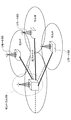
- FIG. 2 is a schematic diagram of a system used in an embodiment of the present invention.
- the system includes a plurality of cells. Each cell includes a base station and a user apparatus (not shown).
- One of the plurality of base stations is referred to as a “central control base station” or a “central base station” (for convenience of illustration, shown as “central BS”).
- the other base station is referred to as a remote base station (shown as “remote BS” in the figure).
- the central base station is connected to a plurality of remote base stations via some communication medium.
- the communication medium is an optical fiber as an example, but may be an electric cable or any appropriate signal transmission medium known in the art.
- the central base station manages the remote base station for predetermined matters.
- the predetermined items are the frequency band used at the cell edge, communication timing (synchronization), the type of pilot channel, whether each user's pilot channel is code division multiplexed, and each user's pilot channel is frequency division multiplexed. Whether or not.
- the predetermined item is also referred to as “instruction content”, and the central base station appropriately notifies the remote base station.
- the frequency band that can be used in each cell is limited so that users at the cell edge use different frequencies in adjacent cells.
- the present invention is applicable even when such frequency band limitation is not performed at the cell edge.
- FIG. 3 shows an example of a frequency usage situation with such restrictions.
- Any cell may use the frequency band indicated by “f 0 ” in the vicinity of its own base station.
- the communication of the data channel at the cell edge of the cell A is limited to the frequency band indicated by “f A ”.
- At the cell edge of the cell A it is prohibited to communicate the data channel in the frequency band “f B ” or “f C ”.
- data channel communication at the cell edge of cell B is limited to the frequency band indicated by “f B ”.
- the cell edge of the cell B it is prohibited to communicate the data channel in the frequency band of “f A ” or “f C ”.
- Communication of the data channel at the cell edge of cell C is limited to the frequency band indicated by “f C ”.
- the cell edge of the cell C it is prohibited to communicate the data channel in the frequency band “f A ” or “f B ”.
- the frequency band that can be used by the cell edge user, it is possible to improve the signal quality for the cell edge user.
- the number of cells and the number of frequency divisions are merely examples, and any appropriate interference coordination may be performed.
- the frequency band (for example, f B , f C in cell A) that should be prohibited from being used in each cell (particularly the cell edge of each cell) may be better changed depending on the communication situation.
- a signal is transmitted in the frequency band of “f B ” or “f C ” at the cell edge of the cell A, communication in the cells B and C is disturbed.
- the pilot channels of each user are multiplexed so as to be orthogonal to each other, and the multiplexing method is managed by the central base station, and the remote base station is instructed as an instruction content. Be notified.
- a central base station and one or more remote base stations form one base station group.
- Each base station appropriately adjusts the transmission timing of the user apparatus so that the reception timing of the uplink signal falls within a certain period.
- the certain period may be set, for example, as a guard interval (or a cyclic prefix period).
- the central base station instructs one or more base stations in the base station group to transmit a pilot channel by a designated method by notifying a certain instruction content.
- the central base station may give some instruction limited to two cells where inter-cell interference is particularly concerned. Alternatively, the central base station may notify the instruction contents to all the cells.
- a user apparatus residing in each cell transmits a pilot channel in the uplink.
- the pilot channel used in this embodiment is composed of orthogonal code sequences.
- the orthogonal code sequence is a CAZAC (Constant Amplitude Zero Auto-Correlation) code sequence.
- the Kazak code sequences before and after the cyclic shift with the same code sequence are orthogonal to each other. By using a Kazak code sequence for the pilot channel, a large number of pilot channels orthogonal to each other can be easily prepared.
- the pilot channel specified in the uplink may be a sounding reference signal (SRS) transmitted in the data channel band, or a demodulation pilot channel (Demodulation RS) attached to the data channel.
- SRS sounding reference signal
- Demodulation RS demodulation pilot channel
- a pilot channel (and a code sequence used for control information data transmission) transmitted in a band prepared exclusively for the control channel may be specified separately from the data channel band.
- a control channel transmitted in a dedicated band is referred to as PUCCH.
- the pilot channel designated by the central base station is notified to each user apparatus via the remote base station, and each user apparatus transmits the designated pilot channel at an appropriate transmission timing.
- the pilot channel transmitted by each user apparatus may be multiplexed in another method instead of or in addition to the code multiplexing method based on the cyclic shift of the Kazak code sequence. For example, assume that a pilot channel in PUCCH is designated.
- PUCCH transmits pilot channels (RS) at four locations in one subframe.
- code multiplexing with a spreading factor of 4 (maximum multiplexing number of 4) can be realized.
- code multiplexing with a spreading factor of 2 may be performed for each 0.5 ⁇ ms slot. Note that not only two illustrated locations in the slot (four locations in the entire subframe) but also all 14 locations in the entire subframe may be used as places where the sign factor is multiplied.
- Code multiplexing can be used when pilot channels are mapped at a plurality of timings in addition to PUCCH. For example, such code multiplexing may be applied to a demodulation pilot channel.
- the pilot channel from each user may be multiplexed not only by code division multiplexing but also by frequency division multiplexing.
- frequency division multiplexing systems include a localized system and a distributed system.
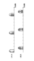
- FIG. 5 shows a state in which pilot signals of each user are multiplexed in a localized manner.
- the sounding reference signal SRS
- the sounding reference signal is transmitted in the entire band of the data channel in principle, but in the case of a cell edge user, it is preferable to limit the transmission band to be narrow and increase the transmission power density.
- SRS sounding reference signal
- FIG. 6 shows a state where pilot signals of each user are multiplexed by the distributed method.
- the signal format of the transmission signal (pilot channel) is converted so as to have signal components distributed at equal intervals on the frequency axis.
- Such signal conversion can be performed by a DFT-Spread OFDM system using discrete Fourier transform (DFT), a variable spreading factor chip repetition factor (VSCRF-CDMA) system, or the like.
- DFT discrete Fourier transform
- VSCRF-CDMA variable spreading factor chip repetition factor
- FIG. 7 is a flowchart showing an operation example according to an embodiment of the present invention.
- the central base station monitors the status of neighboring cells.
- the central base station receives a communication status report from each remote base station, and designates one or more remote base stations accordingly. For example, one or more remote base stations in a cell with poor throughput may be designated.
- step S2 the multiplexing method is determined.
- This multiplexing method specifies the type of pilot channel, whether or not each user's pilot channel is code division multiplexed, whether or not each user's pilot channel is frequency division multiplexed, and the like.
- the “multiplexing method” more generally represents “instruction contents” for the remote base station and the user apparatus.
- step S3 the determined multiplexing method is notified to the remote base station determined in step S1.
- step S4 the method specified by the multiplexing method is notified to the corresponding user device.
- the corresponding user equipment may be specifically designated by the central base station.
- the corresponding user apparatus may be specifically designated by the remote base station.
- the central base station may designate a remote base station, and the remote base station may notify the multiplex transmission method of the designated pilot channel only to the cell edge users.
- step S5 a pilot channel is transmitted by a method specified by the corresponding user apparatus.
- the pilot channel is received within the cyclic prefix period at the remote base station.
- This pilot channel does not cause significant interference to cells other than the remote base station. This is because the above multiplexing method is determined so as to reduce the inter-cell interference. Therefore, by using the pilot channel transmitted in this way, channel estimation can be performed with higher accuracy than in the past.
- FIG. 8 shows a schematic block diagram of a central base station according to an embodiment of the present invention.
- FIG. 8 shows an interface (I / F) 81, a management unit 82, a scheduler 83, a downlink control signal generation unit 84, an OFDM signal generation unit 85, a channel estimation and synchronization unit 86, a cyclic prefix removal unit (-CP) 87.
- a fast Fourier transform unit (FFT) 88 and a restoration unit 89 are depicted.
- Interface (I / F) 81 is an interface for communicating with all remote base stations in the base station group. Any suitable interface may be provided depending on the transmission medium between the central base station and the remote base station. As shown in FIG. 2, the transmission medium may be an optical fiber.
- the management unit 82 includes a timing management unit that manages communication timing of each remote base station, a frequency management unit that manages a frequency band used at the cell edge of each remote base station, and a specific multiplexing method at a specific time point. And a pilot channel management unit for managing pilot channels transmitted in the network. The management unit 82 prepares information corresponding to the above instruction content.
- the scheduler 83 makes an uplink / downlink radio resource allocation plan and outputs a downlink and / or uplink scheduling grant.
- the downlink control signal generation unit 84 generates a downlink control signal including a downlink and / or uplink scheduling grant.
- the OFDM signal generation unit 85 creates a transmission signal including a downlink control signal.
- the transmission signal is formed by the OFDM method.
- the channel estimation and synchronization unit 86 performs synchronization and channel estimation based on the pilot channel received on the uplink.
- the cyclic prefix removal unit (-CP) 87 removes the cyclic prefix from the received signal according to the synchronization timing.
- the fast Fourier transform unit (FFT) 88 performs fast Fourier transform on the received signal and extracts a signal mapped in the frequency domain.
- the restoration unit 89 restores the transmission signal by performing decoding and data demodulation on the extracted signal.
- the present invention is not limited to the above embodiment, and may be applied to any appropriate system using a central base station and a remote base station.
- the present invention may be used with an HSDPA / HSUPA W-CDMA system, an LTE system, an IMT-Advanced system, a WiMAX system, a Wi-Fi system, and the like.
Landscapes
- Engineering & Computer Science (AREA)
- Signal Processing (AREA)
- Computer Networks & Wireless Communication (AREA)
- Mobile Radio Communication Systems (AREA)
Priority Applications (7)
| Application Number | Priority Date | Filing Date | Title |
|---|---|---|---|
| MX2010014532A MX2010014532A (es) | 2008-06-23 | 2009-06-18 | Aparato y metodo de estacion de base. |
| BRPI0914625A BRPI0914625A2 (pt) | 2008-06-23 | 2009-06-18 | aparelho de estação base e método |
| US13/000,853 US20110158150A1 (en) | 2008-06-23 | 2009-06-18 | Base station apparatus and method |
| RU2011101436/07A RU2491790C2 (ru) | 2008-06-23 | 2009-06-18 | Базовая станция и способ управления связью |
| EP09770076.9A EP2293639A4 (en) | 2008-06-23 | 2009-06-18 | Base station apparatus and method |
| CN2009801320748A CN102124801A (zh) | 2008-06-23 | 2009-06-18 | 基站装置以及方法 |
| US14/018,103 US20140016599A1 (en) | 2008-06-23 | 2013-09-04 | Base station apparatus and method for improving channel estimation accuracy in uplink |
Applications Claiming Priority (2)
| Application Number | Priority Date | Filing Date | Title |
|---|---|---|---|
| JP2008163844A JP5068699B2 (ja) | 2008-06-23 | 2008-06-23 | 基地局装置及び方法 |
| JP2008-163844 | 2008-06-23 |
Related Child Applications (1)
| Application Number | Title | Priority Date | Filing Date |
|---|---|---|---|
| US14/018,103 Continuation US20140016599A1 (en) | 2008-06-23 | 2013-09-04 | Base station apparatus and method for improving channel estimation accuracy in uplink |
Publications (1)
| Publication Number | Publication Date |
|---|---|
| WO2009157366A1 true WO2009157366A1 (ja) | 2009-12-30 |
Family
ID=41444434
Family Applications (1)
| Application Number | Title | Priority Date | Filing Date |
|---|---|---|---|
| PCT/JP2009/061124 Ceased WO2009157366A1 (ja) | 2008-06-23 | 2009-06-18 | 基地局装置及び方法 |
Country Status (9)
| Country | Link |
|---|---|
| US (2) | US20110158150A1 (pt) |
| EP (1) | EP2293639A4 (pt) |
| JP (1) | JP5068699B2 (pt) |
| KR (1) | KR101623833B1 (pt) |
| CN (2) | CN102124801A (pt) |
| BR (1) | BRPI0914625A2 (pt) |
| MX (1) | MX2010014532A (pt) |
| RU (2) | RU2491790C2 (pt) |
| WO (1) | WO2009157366A1 (pt) |
Cited By (1)
| Publication number | Priority date | Publication date | Assignee | Title |
|---|---|---|---|---|
| RU2756301C1 (ru) * | 2018-08-09 | 2021-09-29 | ЭлДжи ЭЛЕКТРОНИКС ИНК. | Способ передачи и приема информации о состоянии канала в системе беспроводной связи и устройство для этого |
Families Citing this family (12)
| Publication number | Priority date | Publication date | Assignee | Title |
|---|---|---|---|---|
| WO2007139459A1 (en) * | 2006-05-29 | 2007-12-06 | Telefonaktiebolaget Lm Ericsson (Publ) | Channel quality prediction in hsdpa systems |
| CN105634708B (zh) | 2010-04-22 | 2019-01-18 | Lg电子株式会社 | 用于基站与中继站之间的无线链路的信道估计的方法和设备 |
| CN103024749B (zh) * | 2011-09-27 | 2016-01-13 | 华为技术有限公司 | 一种动态频谱管理的方法和装置 |
| JP5874002B2 (ja) * | 2011-11-10 | 2016-03-01 | パナソニックIpマネジメント株式会社 | 送信装置及び送信方法 |
| US11245486B2 (en) | 2014-10-13 | 2022-02-08 | Nxgen Partners Ip, Llc | Application of orbital angular momentum to Fiber, FSO and RF |
| US10374710B2 (en) | 2014-04-04 | 2019-08-06 | Nxgen Partners Ip, Llc | Re-generation and re-transmission of millimeter waves for building penetration |
| US11956035B2 (en) | 2014-10-13 | 2024-04-09 | Nxgen Partners Ip, Llc | System and method for combining MIMO and mode-division multiplexing |
| US10263670B2 (en) * | 2016-07-21 | 2019-04-16 | NxGen Parners IP, LLC | System and method for reducing pilot signal contamination using orthogonal pilot signals |
| US10726353B2 (en) | 2015-08-03 | 2020-07-28 | Nxgen Partners Ip, Llc | Quantum mechanical framework for interaction of OAM with matter and applications in solid states, biosciences and quantum computing |
| CN107155217A (zh) * | 2016-03-04 | 2017-09-12 | 株式会社Ntt都科摩 | 数据发送方法和用户设备 |
| US11202335B2 (en) | 2019-02-22 | 2021-12-14 | Nxgen Partners Ip, Llc | Combined tunneling and network management system |
| US11152991B2 (en) | 2020-01-23 | 2021-10-19 | Nxgen Partners Ip, Llc | Hybrid digital-analog mmwave repeater/relay with full duplex |
Citations (2)
| Publication number | Priority date | Publication date | Assignee | Title |
|---|---|---|---|---|
| JP2008092051A (ja) * | 2006-09-29 | 2008-04-17 | Nec Corp | 移動通信システムにおける制御信号およびリファレンス信号の多重方法、リソース割当方法および基地局 |
| JP2008163844A (ja) | 2006-12-28 | 2008-07-17 | Hitachi Ltd | スクロール式流体機械 |
Family Cites Families (20)
| Publication number | Priority date | Publication date | Assignee | Title |
|---|---|---|---|---|
| US5982758A (en) * | 1997-02-13 | 1999-11-09 | Hamdy; Walid M. | Method and apparatus for merging neighbor lists in a CDMA mobile telephone system |
| RU2214685C2 (ru) * | 1997-06-20 | 2003-10-20 | Тантиви Коммьюникейшенс, Инк. | Динамическое выделение полосы частот для передачи с помощью протокола беспроводной связи при радиосвязи с множественным доступом с разделением кодов |
| JP2002033716A (ja) * | 2000-07-18 | 2002-01-31 | Sony Corp | Cdma拡散方法およびcdma端末装置 |
| US6829486B2 (en) * | 2000-08-14 | 2004-12-07 | Vesuvius | Communique system for combined cellular and wireline communication networks |
| US7085582B2 (en) * | 2002-07-31 | 2006-08-01 | Motorola, Inc. | Pilot information gain control method and apparatus |
| DE60337035D1 (de) * | 2003-07-29 | 2011-06-16 | Fujitsu Ltd | Pilot-Multiplex-Verfahren und Sendeeinrichtung für einem OFDM-System |
| US8169889B2 (en) * | 2004-02-18 | 2012-05-01 | Qualcomm Incorporated | Transmit diversity and spatial spreading for an OFDM-based multi-antenna communication system |
| KR20060032466A (ko) * | 2004-10-12 | 2006-04-17 | 삼성전자주식회사 | 이동 단말기의 핸드오버를 위한 광대역 무선 접속 통신시스템 및 그 시스템에서의 이동 단말기의 핸드오버 방법 |
| US7782810B2 (en) * | 2004-12-03 | 2010-08-24 | Samsung Electronics Co., Ltd. | Apparatus and method for transmitting/receiving packet data symbol in a mobile communication system |
| KR100913089B1 (ko) * | 2006-02-07 | 2009-08-21 | 엘지전자 주식회사 | 다중 반송파 시스템에 적용되는 파일럿 신호 전송 방법 |
| US8077595B2 (en) * | 2006-02-21 | 2011-12-13 | Qualcomm Incorporated | Flexible time-frequency multiplexing structure for wireless communication |
| US7778151B2 (en) * | 2006-10-03 | 2010-08-17 | Texas Instruments Incorporated | Efficient scheduling request channel for wireless networks |
| WO2008045781A1 (en) * | 2006-10-10 | 2008-04-17 | Qualcomm Incorporated | Uplink pilot multiplexing in su-mimo and sdma for sc-fdma systems |
| US7957759B2 (en) * | 2006-12-08 | 2011-06-07 | Texas Instruments Incorporated | Wideband reference signal transmission in SC-FDMA communication systems |
| DK1942597T3 (da) * | 2007-01-05 | 2013-05-13 | Samsung Electronics Co Ltd | Fremgangsmåde og apparat til videresendelse og modtagelse af styreinformation for randomisering af indgreb mellem celler i et mobilkommunikationssystem |
| KR100945419B1 (ko) * | 2007-03-27 | 2010-03-04 | 삼성전자주식회사 | 광대역 무선통신 시스템에서 슬라이딩 윈도우 채널 추정장치 및 방법 |
| JP5024533B2 (ja) * | 2007-06-19 | 2012-09-12 | 日本電気株式会社 | 移動通信システムにおけるリファレンス信号系列の割当方法および装置 |
| US9357564B2 (en) * | 2007-06-19 | 2016-05-31 | Texas Instruments Incorporated | Signaling of random access preamble parameters in wireless networks |
| JP5213414B2 (ja) * | 2007-10-30 | 2013-06-19 | 株式会社エヌ・ティ・ティ・ドコモ | 移動通信システム、基地局装置、ユーザ装置及び方法 |
| US9246650B2 (en) * | 2008-06-04 | 2016-01-26 | Nokia Solutions And Networks Oy | Method, apparatus and computer program for open loop transmission diversity |
-
2008
- 2008-06-23 JP JP2008163844A patent/JP5068699B2/ja not_active Expired - Fee Related
-
2009
- 2009-06-18 KR KR1020117001556A patent/KR101623833B1/ko active Active
- 2009-06-18 CN CN2009801320748A patent/CN102124801A/zh active Pending
- 2009-06-18 EP EP09770076.9A patent/EP2293639A4/en not_active Withdrawn
- 2009-06-18 BR BRPI0914625A patent/BRPI0914625A2/pt not_active Application Discontinuation
- 2009-06-18 MX MX2010014532A patent/MX2010014532A/es active IP Right Grant
- 2009-06-18 CN CN201310352395.7A patent/CN103428880B/zh active Active
- 2009-06-18 RU RU2011101436/07A patent/RU2491790C2/ru not_active IP Right Cessation
- 2009-06-18 WO PCT/JP2009/061124 patent/WO2009157366A1/ja not_active Ceased
- 2009-06-18 US US13/000,853 patent/US20110158150A1/en not_active Abandoned
-
2013
- 2013-05-06 RU RU2013120140/07A patent/RU2534226C1/ru active
- 2013-09-04 US US14/018,103 patent/US20140016599A1/en not_active Abandoned
Patent Citations (2)
| Publication number | Priority date | Publication date | Assignee | Title |
|---|---|---|---|---|
| JP2008092051A (ja) * | 2006-09-29 | 2008-04-17 | Nec Corp | 移動通信システムにおける制御信号およびリファレンス信号の多重方法、リソース割当方法および基地局 |
| JP2008163844A (ja) | 2006-12-28 | 2008-07-17 | Hitachi Ltd | スクロール式流体機械 |
Non-Patent Citations (4)
| Title |
|---|
| "3GPP TSG RAN WGl Meeting #53 Rl-081948", May 2008, article NTT DOCOMO: "Proposals for LTE-Advanced Technologies", XP008139249 * |
| "Downlink Ll/L2 Control Signaling Channel Structure: Coding", 3GPP RL-070103, 15 January 2007 (2007-01-15) |
| "Physical Layer Aspects for Evolved UTRA", 3GPP TR 25.814, June 2006 (2006-06-01) |
| See also references of EP2293639A4 |
Cited By (1)
| Publication number | Priority date | Publication date | Assignee | Title |
|---|---|---|---|---|
| RU2756301C1 (ru) * | 2018-08-09 | 2021-09-29 | ЭлДжи ЭЛЕКТРОНИКС ИНК. | Способ передачи и приема информации о состоянии канала в системе беспроводной связи и устройство для этого |
Also Published As
| Publication number | Publication date |
|---|---|
| RU2011101436A (ru) | 2012-07-27 |
| JP2010004500A (ja) | 2010-01-07 |
| KR20110031348A (ko) | 2011-03-25 |
| CN103428880B (zh) | 2018-06-15 |
| RU2491790C2 (ru) | 2013-08-27 |
| RU2534226C1 (ru) | 2014-11-27 |
| RU2013120140A (ru) | 2014-11-20 |
| BRPI0914625A2 (pt) | 2015-10-20 |
| CN102124801A (zh) | 2011-07-13 |
| EP2293639A1 (en) | 2011-03-09 |
| MX2010014532A (es) | 2011-02-22 |
| JP5068699B2 (ja) | 2012-11-07 |
| US20110158150A1 (en) | 2011-06-30 |
| US20140016599A1 (en) | 2014-01-16 |
| KR101623833B1 (ko) | 2016-05-24 |
| CN103428880A (zh) | 2013-12-04 |
| EP2293639A4 (en) | 2016-08-24 |
Similar Documents
| Publication | Publication Date | Title |
|---|---|---|
| JP5068699B2 (ja) | 基地局装置及び方法 | |
| EP2613600B1 (en) | Wireless communication system, wireless base station device, and mobile terminal device | |
| RU2507719C2 (ru) | Терминал пользователя, базовая станция и способ связи в системе мобильной связи | |
| EP3096478B1 (en) | Method for transmitting uplink control information, wireless terminal and base station | |
| CN110050452B (zh) | 基站装置、终端装置、通信方法及集成电路 | |
| EP2555574B1 (en) | Mobile communication system, base station apparatus, mobile station apparatus, mobile communication method and integrated circuit | |
| JP2018061273A (ja) | 無線通信端末およびリソース割当方法 | |
| CN101822120A (zh) | 基站装置 | |
| JP6636112B2 (ja) | 端末及び無線通信方法 | |
| JP2011238980A (ja) | 基地局装置、移動端末装置および通信制御方法 | |
| CN102007724A (zh) | 移动通信系统、发送装置、接收装置及方法 | |
| JP5820246B2 (ja) | 無線通信システム、無線通信方法、無線基地局装置及びユーザ端末 | |
| EP2608597A1 (en) | Base station apparatus, mobile terminal apparatus and communication control method | |
| JP5107337B2 (ja) | 移動通信システムで使用される基地局及び方法 | |
| JP5249454B2 (ja) | ユーザ装置 | |
| KR20140129986A (ko) | 간섭 제어를 위해 스몰셀에 적합한 제어신호 구조 | |
| KR20140129984A (ko) | 사용자신호검출을 위한 제어신호를 통한 셀간 간섭 제어 |
Legal Events
| Date | Code | Title | Description |
|---|---|---|---|
| WWE | Wipo information: entry into national phase |
Ref document number: 200980132074.8 Country of ref document: CN |
|
| 121 | Ep: the epo has been informed by wipo that ep was designated in this application |
Ref document number: 09770076 Country of ref document: EP Kind code of ref document: A1 |
|
| WWE | Wipo information: entry into national phase |
Ref document number: MX/A/2010/014532 Country of ref document: MX |
|
| WWE | Wipo information: entry into national phase |
Ref document number: 4911/KOLNP/2010 Country of ref document: IN |
|
| NENP | Non-entry into the national phase |
Ref country code: DE |
|
| WWE | Wipo information: entry into national phase |
Ref document number: 2009770076 Country of ref document: EP |
|
| ENP | Entry into the national phase |
Ref document number: 20117001556 Country of ref document: KR Kind code of ref document: A |
|
| WWE | Wipo information: entry into national phase |
Ref document number: 2011101436 Country of ref document: RU |
|
| ENP | Entry into the national phase |
Ref document number: PI0914625 Country of ref document: BR Kind code of ref document: A2 Effective date: 20101223 |