WO2009157443A1 - Système de radiocommunication, dispositif de station mobile et procédé de réception radio - Google Patents
Système de radiocommunication, dispositif de station mobile et procédé de réception radio Download PDFInfo
- Publication number
- WO2009157443A1 WO2009157443A1 PCT/JP2009/061404 JP2009061404W WO2009157443A1 WO 2009157443 A1 WO2009157443 A1 WO 2009157443A1 JP 2009061404 W JP2009061404 W JP 2009061404W WO 2009157443 A1 WO2009157443 A1 WO 2009157443A1
- Authority
- WO
- WIPO (PCT)
- Prior art keywords
- subframe
- type
- unit
- data
- multicast
- Prior art date
- Legal status (The legal status is an assumption and is not a legal conclusion. Google has not performed a legal analysis and makes no representation as to the accuracy of the status listed.)
- Ceased
Links
Images









Classifications
-
- H—ELECTRICITY
- H04—ELECTRIC COMMUNICATION TECHNIQUE
- H04L—TRANSMISSION OF DIGITAL INFORMATION, e.g. TELEGRAPHIC COMMUNICATION
- H04L5/00—Arrangements affording multiple use of the transmission path
- H04L5/0001—Arrangements for dividing the transmission path
- H04L5/0014—Three-dimensional division
- H04L5/0023—Time-frequency-space
-
- H—ELECTRICITY
- H04—ELECTRIC COMMUNICATION TECHNIQUE
- H04L—TRANSMISSION OF DIGITAL INFORMATION, e.g. TELEGRAPHIC COMMUNICATION
- H04L27/00—Modulated-carrier systems
- H04L27/0008—Modulated-carrier systems arrangements for allowing a transmitter or receiver to use more than one type of modulation
-
- H—ELECTRICITY
- H04—ELECTRIC COMMUNICATION TECHNIQUE
- H04L—TRANSMISSION OF DIGITAL INFORMATION, e.g. TELEGRAPHIC COMMUNICATION
- H04L27/00—Modulated-carrier systems
- H04L27/26—Systems using multi-frequency codes
- H04L27/2601—Multicarrier modulation systems
- H04L27/2602—Signal structure
-
- H—ELECTRICITY
- H04—ELECTRIC COMMUNICATION TECHNIQUE
- H04L—TRANSMISSION OF DIGITAL INFORMATION, e.g. TELEGRAPHIC COMMUNICATION
- H04L27/00—Modulated-carrier systems
- H04L27/32—Carrier systems characterised by combinations of two or more of the types covered by groups H04L27/02, H04L27/10, H04L27/18 or H04L27/26
- H04L27/34—Amplitude- and phase-modulated carrier systems, e.g. quadrature-amplitude modulated carrier systems
- H04L27/3488—Multiresolution systems
-
- H—ELECTRICITY
- H04—ELECTRIC COMMUNICATION TECHNIQUE
- H04L—TRANSMISSION OF DIGITAL INFORMATION, e.g. TELEGRAPHIC COMMUNICATION
- H04L5/00—Arrangements affording multiple use of the transmission path
- H04L5/003—Arrangements for allocating sub-channels of the transmission path
- H04L5/0037—Inter-user or inter-terminal allocation
-
- H—ELECTRICITY
- H04—ELECTRIC COMMUNICATION TECHNIQUE
- H04L—TRANSMISSION OF DIGITAL INFORMATION, e.g. TELEGRAPHIC COMMUNICATION
- H04L5/00—Arrangements affording multiple use of the transmission path
- H04L5/003—Arrangements for allocating sub-channels of the transmission path
- H04L5/0058—Allocation criteria
- H04L5/0064—Rate requirement of the data, e.g. scalable bandwidth, data priority
-
- H—ELECTRICITY
- H04—ELECTRIC COMMUNICATION TECHNIQUE
- H04L—TRANSMISSION OF DIGITAL INFORMATION, e.g. TELEGRAPHIC COMMUNICATION
- H04L5/00—Arrangements affording multiple use of the transmission path
- H04L5/0091—Signalling for the administration of the divided path, e.g. signalling of configuration information
- H04L5/0094—Indication of how sub-channels of the path are allocated
-
- H—ELECTRICITY
- H04—ELECTRIC COMMUNICATION TECHNIQUE
- H04W—WIRELESS COMMUNICATION NETWORKS
- H04W52/00—Power management, e.g. Transmission Power Control [TPC] or power classes
- H04W52/04—Transmission power control [TPC]
- H04W52/18—TPC being performed according to specific parameters
- H04W52/28—TPC being performed according to specific parameters using user profile, e.g. mobile speed, priority or network state, e.g. standby, idle or non-transmission
- H04W52/281—TPC being performed according to specific parameters using user profile, e.g. mobile speed, priority or network state, e.g. standby, idle or non-transmission taking into account user or data type priority
-
- H—ELECTRICITY
- H04—ELECTRIC COMMUNICATION TECHNIQUE
- H04W—WIRELESS COMMUNICATION NETWORKS
- H04W52/00—Power management, e.g. Transmission Power Control [TPC] or power classes
- H04W52/04—Transmission power control [TPC]
- H04W52/54—Signalisation aspects of the TPC commands, e.g. frame structure
- H04W52/58—Format of the TPC bits
-
- H—ELECTRICITY
- H04—ELECTRIC COMMUNICATION TECHNIQUE
- H04W—WIRELESS COMMUNICATION NETWORKS
- H04W72/00—Local resource management
- H04W72/12—Wireless traffic scheduling
-
- H—ELECTRICITY
- H04—ELECTRIC COMMUNICATION TECHNIQUE
- H04L—TRANSMISSION OF DIGITAL INFORMATION, e.g. TELEGRAPHIC COMMUNICATION
- H04L25/00—Baseband systems
- H04L25/02—Details ; arrangements for supplying electrical power along data transmission lines
- H04L25/0202—Channel estimation
- H04L25/0224—Channel estimation using sounding signals
- H04L25/0226—Channel estimation using sounding signals sounding signals per se
-
- H—ELECTRICITY
- H04—ELECTRIC COMMUNICATION TECHNIQUE
- H04L—TRANSMISSION OF DIGITAL INFORMATION, e.g. TELEGRAPHIC COMMUNICATION
- H04L5/00—Arrangements affording multiple use of the transmission path
- H04L5/003—Arrangements for allocating sub-channels of the transmission path
- H04L5/0048—Allocation of pilot signals, i.e. of signals known to the receiver
-
- H—ELECTRICITY
- H04—ELECTRIC COMMUNICATION TECHNIQUE
- H04L—TRANSMISSION OF DIGITAL INFORMATION, e.g. TELEGRAPHIC COMMUNICATION
- H04L5/00—Arrangements affording multiple use of the transmission path
- H04L5/003—Arrangements for allocating sub-channels of the transmission path
- H04L5/0058—Allocation criteria
- H04L5/006—Quality of the received signal, e.g. BER, SNR, water filling
-
- H—ELECTRICITY
- H04—ELECTRIC COMMUNICATION TECHNIQUE
- H04W—WIRELESS COMMUNICATION NETWORKS
- H04W52/00—Power management, e.g. Transmission Power Control [TPC] or power classes
- H04W52/04—Transmission power control [TPC]
- H04W52/06—TPC algorithms
- H04W52/14—Separate analysis of uplink or downlink
- H04W52/146—Uplink power control
-
- H—ELECTRICITY
- H04—ELECTRIC COMMUNICATION TECHNIQUE
- H04W—WIRELESS COMMUNICATION NETWORKS
- H04W72/00—Local resource management
- H04W72/20—Control channels or signalling for resource management
- H04W72/23—Control channels or signalling for resource management in the downlink direction of a wireless link, i.e. towards a terminal
-
- H—ELECTRICITY
- H04—ELECTRIC COMMUNICATION TECHNIQUE
- H04W—WIRELESS COMMUNICATION NETWORKS
- H04W72/00—Local resource management
- H04W72/30—Resource management for broadcast services
Definitions
- the present invention relates to a radio communication system, a mobile station apparatus, and a radio reception method.
- This application claims priority based on Japanese Patent Application No. 2008-165110 filed in Japan on June 24, 2008, the contents of which are incorporated herein by reference.
- W-CDMA Wideband Code Division Multiple Access
- 3GPP 3rd Generation Partnership Project
- EUTRA Evolved Universal Terrestrial Radio Access
- 3G network evolution Evolved Universal Terrestrial Network, which is referred to as “Evaluated Universal Access Network”;
- An OFDM (Orthogonal Frequency Division Multiplexing) scheme which is multicarrier transmission, has been proposed as a downlink that is transmission from a base station apparatus of EUTRA to a mobile station apparatus.
- a single carrier transmission DFT-Spread OFDM (Discrete Fourier Transform-Spread OFDM; discrete Fourier transform-spread orthogonal frequency division multiplexing) system single A carrier communication system has been proposed.
- the base station apparatus BS1 performs radio communication with the mobile station apparatuses UE1, UE2, and UE3.
- the downlink which is radio communication from the EUTRA base station device BS1 to the mobile station devices UE1, UE2, UE3, is a downlink pilot channel, a downlink synchronization channel, a broadcast channel, a downlink control channel, a downlink shared data channel, a control. It consists of a format indicator channel, a downlink HARQ (Hybrid Automatic Repeat reQuest) indicator channel, and a multicast channel.
- the uplink which is radio communication from the mobile station apparatuses UE1, UE2, UE3 of the EUTRA to the base station apparatus BS1, includes an uplink pilot channel, a random access channel, an uplink control channel, and an uplink shared data channel. It is comprised by.
- FIG. 15 is a diagram illustrating a schematic configuration of a downlink radio frame in EUTRA (Non-Patent Document 1 Section 6.2).
- FIG. 15 shows, as an example, a schematic configuration of a unicast subframe of a radio frame when time-multiplexing a downlink control channel and a downlink shared data channel.
- the horizontal axis is the time axis
- the vertical axis is the frequency axis.
- the downlink radio frame is composed of a plurality of physical resource block PRB (Physical Resource Block) pairs.
- PRB Physical Resource Block
- one physical resource block PRB pair is composed of two physical resource blocks PRB (PRB bandwidth ⁇ slot) continuous in the time domain.
- one physical resource block PRB is composed of 12 subcarriers in the frequency domain. It consists of 7 OFDM symbols in the region.
- the system bandwidth is a communication bandwidth of the base station device.
- a unit composed of one subcarrier and one OFDM symbol is called a resource element.
- a plurality of physical resource blocks PRB corresponding to the system bandwidth are arranged in the frequency direction.
- multicast subframe Multicast / Broadcast over Single Frequency Network Subframe
- each unicast subframe at least a downlink shared data channel used for transmitting information data and system information and a downlink control channel used for transmitting control data are arranged.
- the system information includes information necessary for communication between the base station apparatus and the mobile station apparatus, and is periodically transmitted to an unspecified number of mobile station apparatuses using the broadcast channel and the downlink shared data channel. .
- the items of system information arranged in the broadcast channel and the downlink shared data channel are different, and the system information arranged in the broadcast channel depends on the system bandwidth, the setting information of the downlink HARQ indicator channel, the number of transmission antennas, and the like. Composed.
- the system information arranged in the downlink shared data channel includes uplink and downlink transmission power control information, setting information of subframes of adjacent base station apparatuses, and subframes of the base station apparatus (located base station apparatus). Configuration information.
- FIG. 15 shows a case where the downlink control channel is arranged in the first, second and third OFDM symbols from the top of the subframe, and the downlink shared data channel is arranged in other OFDM symbols.
- the number of OFDM symbols in which the downlink control channel is arranged varies in subframe units.
- the control format indicator channel indicating the number of OFDM symbols constituting the downlink control channel is arranged at a predetermined frequency position of the first OFDM symbol.
- the downlink control channel is arranged only in the first OFDM symbol, is arranged in the first and second OFDM symbols, or is arranged over the first to third OFDM symbols. The description of the arrangement of the control format indicator channel will be described later.
- the downlink HARQ indicator channel is arranged in the OFDM symbol in which the downlink control channel is arranged, that is, frequency-multiplexed with the downlink control channel. Note that the downlink control channel and the downlink shared data channel are not arranged together in the same OFDM symbol.
- a plurality of uplink radio resource allocation information, downlink radio resource allocation information, transmission power command information, and the like are arranged in the downlink control channel of the unicast subframe. Details of the information arranged in the downlink control channel will be described later.
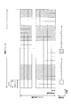
- FIG. 16 is a diagram illustrating the arrangement of downlink pilot channels within one physical resource block PRB pair in a unicast subframe of EUTRA downlink (Non-Patent Document 1 Section 6.10.1).
- the horizontal axis is the time axis
- the vertical axis is the frequency axis.
- resource elements denoted by reference symbol R ⁇ b> 1 represent resource elements of a downlink pilot channel transmitted from the transmission antenna 1.
- a resource element to which a symbol R2 is attached represents a resource element of a downlink pilot channel transmitted from the transmission antenna 2.
- the resource element to which the symbol R3 is attached represents the resource element of the downlink pilot channel transmitted from the transmission antenna 3.
- a resource element denoted by reference symbol R4 represents a resource element of a downlink pilot channel transmitted from the transmission antenna 4.
- the downlink control channel is transmitted in resource elements R3 and R4 in the second OFDM symbol, and the downlink is transmitted in resource elements R3 and R4 in the ninth OFDM symbol.
- a link shared data channel is transmitted. Note that, since it is not related to the present invention, details on the broadcast channel and the downlink synchronization channel are omitted, but the broadcast channel and the downlink synchronization channel are predetermined resource elements of a predetermined subframe. Placed in.
- FIG. 17 is a diagram illustrating a schematic configuration of a multicast subframe in the downlink of EUTRA (Non-Patent Documents 16.5 and 6.10.2).
- the horizontal axis is the time axis
- the vertical axis is the frequency axis.
- one physical resource block PRB is composed of 12 subcarriers in the frequency domain, and is composed of 6 OFDM symbols in the time domain.
- a slot is composed of 6 OFDM symbols
- a subframe is composed of 2 slots.
- Each multicast subframe includes at least a plurality of multicast data (MBMS (Multimedia Broadcast / Multicast Service) data; hereinafter referred to as “multicast data”) and a downlink control channel used to transmit control data.
- MBMS Multimedia Broadcast / Multicast Service
- the multicast data is multicast data in a broad sense indicating data addressed to a plurality of mobile station devices, and broadcast data addressed to an unspecified number of mobile station devices and a narrow sense addressed to a specified number of mobile station devices. It is a general term for multicast data.
- the term “multicast data” refers to multicast data in a broad sense.
- the downlink pilot channel used for channel estimation of the multicast channel and the downlink control channel is not shown in FIG. 17, and the arrangement thereof will be described later.
- the downlink control channel is arranged in the first and second OFDM symbols from the top of the subframe, and the multicast channel is arranged in other OFDM symbols, but the downlink control channel is arranged.
- the number of OFDM symbols to be changed varies in subframe units.
- the number of OFDM symbols that make up a multicast subframe is less than the number of OFDM symbols that make up a unicast subframe, but the OFDM symbol length in which the multicast channel is arranged is compared to the OFDM length of the unicast subframe.
- the slot length of the multicast subframe and the unicast subframe is the same.
- the length of the OFDM symbol in which the downlink control channel (shaded hatching portion) of the multicast subframe is arranged is the same as the OFDM symbol length of the downlink control channel of the unicast subframe.
- a spare sample (shaded hatch portion) is placed between the OFDM symbol of the downlink control channel and the OFDM symbol of the multicast channel. Deploy. For example, “0” may be arranged as a spare sample.
- the control format indicator channel indicating the number of OFDM symbols constituting the downlink control channel is arranged at a predetermined frequency position of the first OFDM symbol.
- the downlink control channel is arranged only in the first OFDM symbol, or arranged in the first and second OFDM symbols. Unlike the unicast subframe, in the multicast subframe, the downlink control channel is not arranged in the third OFDM symbol.
- the downlink HARQ indicator channel is arranged in the OFDM symbol in which the downlink control channel is arranged, that is, frequency-multiplexed with the downlink control channel.
- the downlink control channel and the multicast channel are not arranged together in the same OFDM symbol.
- uplink radio resource allocation information, transmission power command information, and the like are arranged, and downlink radio resource allocation information is not arranged. Details of the information arranged in the downlink control channel will be described later.
- FIG. 18 is a diagram for explaining the arrangement of downlink pilot channels within one physical resource block PRB pair in a downlink multicast subframe of EUTRA (Non-Patent Document 1 Section 6.10.2).
- the horizontal axis is the time axis
- the vertical axis is the frequency axis.
- resource elements to which reference symbol R ⁇ b> 1 is attached represent resource elements of a downlink pilot channel transmitted from the transmission antenna 1.
- a resource element to which a symbol R2 is attached represents a resource element of a downlink pilot channel transmitted from the transmission antenna 2.
- the resource element to which the symbol R3 is attached represents the resource element of the downlink pilot channel transmitted from the transmission antenna 3.
- a resource element denoted by reference symbol R4 represents a resource element of a downlink pilot channel transmitted from the transmission antenna 4.
- a resource element denoted by reference symbol R5 represents a resource element of a downlink pilot channel transmitted from the transmission antenna 5.
- Resource elements R1, R2, R3, and R4 are arranged in the OFDM symbol constituting the downlink control channel, and the arrangement is the same as that of the unicast subframe, and is used for propagation path compensation of the downlink control channel.
- the resource element R5 is arranged in the OFDM symbol constituting the multicast channel and is used for propagation channel compensation of the multicast channel.
- the link control channel is always arranged in both the first and second. If the base station apparatus has three transmission antennas, the downlink control channel is transmitted by two transmission antennas, and the multicast channel is transmitted by the remaining one transmission antenna. Thus, when transmitting a downlink control channel with two transmission antennas, the downlink control channel is transmitted in resource elements R3 and R4 in the second OFDM symbol.
- Multicast> In EUTRA, a multimedia broadcast / multicast service (hereinafter referred to as “multicast”) in which a base station device transmits data to an unspecified number of mobile station devices has been proposed (Non-patent Document 2 15). section). Also, in multicast, single cell transmission in which one base station device transmits data to an unspecified number of mobile station devices and the same simultaneously from a plurality of synchronized base station devices to an unspecified number of mobile station devices Multi-cell transmission for transmitting data has been proposed. Multi-cell transmission has the following characteristics.
- An MBSFN area (hereinafter referred to as “multicast area”) that is synchronized by a plurality of base station apparatuses and performs multicast (or broadcast) at the same frequency at the same time is configured.
- a plurality of base station devices in the multicast area simultaneously transmit the same multicast data toward an unspecified number of mobile station devices.
- the mobile station apparatus can synthesize multicast data transmitted simultaneously from a plurality of base station apparatuses.
- Multicast data is transmitted on the multicast channel of the multicast subframe.
- the multicast channel is transmitted from one antenna.
- description of single cell transmission is abbreviate
- FIG. 19 is a diagram illustrating a schematic configuration of a radio frame of a multicast / unicast mixed cell that performs multi-cell transmission.
- the horizontal axis is the time axis
- the vertical axis is the frequency axis.
- the first, fourth to sixth and eighth subframes of the radio frame are unicast subframes, and the rest are multicast subframes.
- a radio frame of a multicast / unicast mixed cell that performs multi-cell transmission has the following characteristics.
- the multicast subframe and the unicast subframe are time multiplexed.
- Multicast data is transmitted on the multicast channel of the multicast subframe.
- Information data and system information are transmitted in a unicast subframe, information data is transmitted in a downlink shared data channel, and system information is transmitted in a downlink shared data channel and a broadcast channel.
- the first and sixth subframes of the radio frame are always unicast subframes, and at least a synchronization channel is transmitted.
- Multicast subframe arrangement pattern In the base station apparatus that performs multi-cell transmission, information on the arrangement of subframes reserved for multicast subframes, that is, information that designates subframes in which multicast subframes can be arranged (MBSFN subframe allocation pattern (MSAP); “Multicast subframe arrangement pattern” (sometimes called MBSFN subframe configuration (MBSC) or MBSFN subframe allocation signaling, etc. in the third generation partnership project) is transmitted in the system information of the downlink shared data channel (non-patented) Reference 3).
- MBSFN subframe allocation pattern (MSAP); “Multicast subframe arrangement pattern” (sometimes called MBSFN subframe configuration (MBSC) or MBSFN subframe allocation signaling, etc. in the third generation partnership project) is transmitted in the system information of the downlink shared data channel (non-patented) Reference 3).
- FIG. 20 is a diagram for explaining a multicast subframe arrangement pattern of a multicast / unicast mixed cell for multi-cell transmission.
- the horizontal axis is a time axis
- the vertical axis is a frequency axis.
- the multicast subframe arrangement pattern indicates the arrangement of subframes reserved for multicast subframes in a certain period. In the next period, if the multicast subframe arrangement pattern is not changed, the same period in the next multicast subframe arrangement pattern is used.
- a subframe is reserved as a multicast subframe.
- FIG. 21 illustrates subframe information (dynamic scheduling information) in which multicast data arranged in a multicast channel is transmitted in a plurality of subframes indicated by a multicast subframe arrangement pattern transmitted by a base station apparatus that performs multicell transmission.
- dynamic scheduling information the horizontal axis is the time axis
- the vertical axis is the frequency axis.
- the multicast channel on which dynamic scheduling information and multicast data are arranged is shown, and other channels such as a downlink control channel and a downlink shared data channel are not shown.
- Dynamic scheduling information is represented by a hatched square, and multicast data is represented by a hatched square.
- the dynamic scheduling information indicates in which subframe multicast data 1 to 5 are arranged.
- the dynamic scheduling information is multiplexed with multicast data 1 in one subframe.
- the dynamic scheduling information has the following characteristics (Non-Patent Document 5). (1) A subframe in which one or a plurality of multicast data is arranged. (2) It may be multiplexed with multicast data within a subframe. (3) A plurality of dynamic scheduling information may be included in the period of the multicast subframe arrangement pattern.
- Multicast / unicast for multi-cell transmission when the base station device loses part of the multicast data to be transmitted on the multicast channel, multicast is performed based on the amount of data that can be multicast according to the applied multicast subframe arrangement pattern. When there is little data, out of the subframes that can place the multicast subframes specified in the multicast subframe placement pattern, the subframes that are affected by the small amount do not transmit multicast data, but unicast it. Subframes are being considered.
- Non-Patent Document 2 Section 153.3 support for a method in which the mobile station apparatus detects that the multicast data is not transmitted in the subframe indicated that the multicast subframe can be arranged in the multicast subframe arrangement pattern, or notifies the mobile station apparatus.
- Control Data Format (DCI (Downlink Control Information) format)> A plurality of control data are arranged in the downlink control channel. Further, there are at least the following three types of control data arranged in the downlink control channel.
- Radio resource allocation control data of a downlink shared data channel for one mobile station apparatus (hereinafter referred to as “downlink radio resource allocation information”).
- Control data for radio resource allocation of an uplink shared data channel for one mobile station apparatus (hereinafter referred to as “uplink radio resource allocation information”).
- Control data (hereinafter referred to as “transmission power command information”) consisting of a set of transmission power control commands (hereinafter referred to as “transmission power command”) of the uplink shared data channel and the uplink control channel for one mobile station apparatus. Called).
- transmission power command information consisting of a set of transmission power control commands (hereinafter referred to as “transmission power command”) of the uplink shared data channel and the uplink control channel for one mobile station apparatus. Called).
- Downlink radio resource assignment information includes downlink shared data channel radio resource assignment information, mobile station identifier, modulation scheme, coding rate, retransmission parameter, At least one transmission power command for the uplink control channel is included. Furthermore, it is classified into the following three according to the purpose.
- the size of the radio resource allocation information of the downlink shared data channel is the smallest, and downlink radio resource allocation information (hereinafter referred to as “SIMO”) for single input multiple output (hereinafter referred to as “SIMO”). , Referred to as “downlink radio resource allocation information 1”).
- the size of the radio resource allocation information of the downlink shared data channel is larger than that of the downlink radio resource allocation information 1, and the downlink radio resource allocation information for SIMO (hereinafter, “downlink radio resource allocation information 2”) Called).
- the size of the radio resource allocation information of the downlink shared data channel is the same as that of the downlink radio resource allocation information 2, and includes a multiple input multiple output (Multiple output) each including two modulation schemes, coding rates, and retransmission parameters.
- Multiple output multiple input multiple output
- Downlink radio resource allocation information 3 for Input Multiple Output (hereinafter referred to as “MIMO”).
- MIMO Input Multiple Output
- the number of bits (size) constituting these three downlink radio resource allocation information is different. Also, since no downlink shared data channel is arranged in the multicast subframe, no downlink radio resource allocation information is arranged in the downlink control channel of the multicast subframe. Note that the transmission power command included in the downlink radio resource allocation information is an uplink control channel transmission power command used when transmitting a reception response signal for the downlink shared data channel.
- the uplink radio resource allocation information includes a mobile station identifier, uplink radio resource allocation information, a modulation scheme, a coding rate, a retransmission parameter, and the like.
- the uplink and downlink system bandwidths are the same, the number of bits (size) constituting the uplink radio resource allocation information and the downlink radio resource allocation information 1 are the same.
- the transmission power command information includes transmission power commands and mobile station group identifiers for a plurality of mobile station apparatuses.
- the number of bits (size) constituting transmission power command information and uplink radio resource allocation information is the same.
- FIG. 22 is a flowchart for explaining an example of a procedure for encoding control data arranged in a downlink control channel (Non-Patent Document 6, section 53.3).
- the control data input from the control unit and the error detection code are multiplexed.
- the error detection code is generated from the control data using a predetermined generator polynomial.
- the control data multiplexed with the error detection code is convolutionally encoded.
- the convolutionally encoded control data is rate-matched and then output to a QPSK (Quadrature Phase Shift Keying) modulator. Details of the rate matching will be described later.
- the control data after rate matching is QPSK modulated and mapped to the resource element of the downlink control channel.
- the combination of resource elements of the downlink control channel to which the control data is mapped is limited by the size of the control data after QPSK modulation.
- a base station apparatus transmits a downlink control channel using transmission diversity, after QPSK modulation, a transmission diversity process is performed and mapped to the resource element of a downlink control channel.
- Rate matching is a process of repeating control data that has been subjected to convolutional coding and a puncture in order to match the size of control data that has been subjected to convolutional coding and the size of the physical resource of the downlink control channel to which the control data is mapped. ) Process to change the coding rate.
- rate matching is performed so that the size of 36 resource elements, 72 resource elements, 144 resource elements, and 288 resource elements is obtained after QPSK modulation.
- the patterns to be repeated or thinned out to match different control data sizes with different physical resources are different. That is, different rate matching patterns are used for control data of different sizes such as downlink radio resource allocation information 2 and uplink radio resource allocation information.
- different rate matching patterns are used.
- FIG. 23 is a flowchart for explaining an example of a procedure for decoding control data arranged in the downlink control channel.
- the mobile station apparatus monitors whether the control data addressed to the mobile station apparatus is arranged in the downlink control channel for each subframe. However, since the mobile station apparatus does not know how many items of control data for which item are addressed to the mobile station apparatus, how many resource elements have been rate-matched, and which resource element has been mapped, For all combinations of resource elements and rate matching, brute force decoding is performed in which brute force is tried.
- the mobile station apparatus first QPSK-demodulates all the resource elements constituting the downlink control channel (S1), and sets the number of resource elements to which control data may be mapped and the combination of arrangement to 1 One resource element is extracted (S2). Next, one possible size of control data before rate matching is selected, and the reverse processing of rate matching determined by the size of the selected control data and the number of extracted resource elements (hereinafter referred to as “rate dematching”). (S3).
- control data after rate dematching is convolutionally decoded (S4), and error detection is performed using an error detection code (S5).
- an error detection code is used in which the error detection calculation result is the identification number of the destination mobile station apparatus of the control data.
- the mobile station apparatus transmits its control data to the mobile station apparatus. It is recognized that the control data is addressed, and further, it is recognized whether the control data is uplink radio resource allocation information, downlink radio resource allocation information or transmission power command information by looking at the configuration of the control data (S7).
- the control data is uplink radio resource allocation information, downlink radio resource allocation information, and the transmission power command information is decoded (S8-No)
- the decoding process ends.
- the uplink radio resource allocation information when there is control data that has not been decoded yet (S8-Yes), the resource element to which the control data that has not been tried is mapped
- the number, the combination of arrangement, and the size of control data before rate matching are set (S9), and the processing from step S2 for extracting resource elements from the downlink control channel is repeated.
- step S6-Yes When an error is detected in the error detection process in step S5 (S6-Yes), the number of resource elements to which control data not yet tried is mapped, and the combination of arrangement and the size of control data before rate matching exist (S10-Yes), set them (S9), and repeat the process from step S2 to extract the resource elements from the downlink control channel. Also, when the control data decoding process is performed for the number of resource elements to which all control data is mapped, the combination of arrangements, and the size of the control data before rate matching (No in S10), the decoding process ends. To do. When the base station apparatus transmits a downlink control channel using transmission diversity, QPSK demodulation in step S1 is performed after performing transmission diversity combining processing.
- 3GPP TS 36.211-v8.1.0 (2007-11), Physical Channels and Modulation (Release 8) 3GPP TS36.300-v8.3.0 (2007-12), Overall description; Stage 2 (Release 8) 3GPP TSG RAN1 # 51b, Severilla, Spain, 14-18 January, 2008, R1-080621 “Physical-layer” parameters to be configured RCC ” 3GPP TSG RAN2 # 61, Sorrento, Italy, 11-15 February, 2008, R2-080708 “LS response on Signaling of MBSFN Subframe Allocation” 3GPP TSG RAN2 # 61, Sorrento, Italy, 11-15 February, 2008, R2-080875 "MBMS scheduling information and paging occassion relation relation to MBMS subframe" 3GPP TS36.212-v8.1.0 (2007-11), Multiplexing and channel coding (Release 8)
- the mobile station apparatus determines how many items of control data for the mobile station apparatus are included in the downlink control channel, how many resource elements have been rate-matched, and which resource element Since it is not possible to recognize whether or not it has been mapped to a possible resource element and rate matching, the processing load related to reception of the downlink control channel is performed because brute force decoding is attempted for brute force decoding. There is a problem that is heavy.
- the present invention has been made in view of such circumstances, and an object of the present invention is to provide a radio communication system, a mobile station apparatus, and a radio reception method capable of suppressing a processing load related to reception of a downlink control channel. There is to do.
- the present invention has been made to solve the above-described problems, and the wireless communication system of the present invention is a first type subframe in which first type data is arranged and a second type data in which second type data is arranged.
- a wireless communication system comprising: a base station device that multiplexes and transmits two types of subframes; and a plurality of mobile station devices that receive signals addressed to the device from the subframes transmitted by the base station device
- the base station apparatus includes: a radio resource control unit that determines a type of each of the subframes; a control signal generation unit that generates a control data signal including items according to the types of the subframes arranged; Of the subframes specified by the first type subframe candidate information stored in advance and specifying the subframes in which the type subframes can be arranged, the first type subframes are included.
- a dynamic scheduling information signal generation unit for generating a dynamic scheduling information signal indicating a subframe to be a frame, and the control data signal is disposed in the first type subframe and the second type subframe,
- a multiplexing unit that arranges a signal of scheduling information in the first type subframe, and a transmission unit that transmits a signal of a multiplexing result by the multiplexing unit, wherein the mobile station device is transmitted from the base station device
- a receiving unit that receives a signal a dynamic scheduling information detecting unit that detects the dynamic scheduling information from the received signal, the first type subframe candidate information that is held in advance, and the dynamic scheduling information.
- the type of each subframe of the received signal A frame type determination unit to be determined, and a control data detection unit that performs detection processing of the control data of an item corresponding to the type indicated by the determination result of the frame type determination unit for each subframe of the received signal It is characterized by comprising.
- wireless communications system of this invention is the above-mentioned radio
- the radio communication system of the present invention is the above-described radio communication system, wherein the dynamic scheduling information is arranged in a subframe designated by the first type subframe candidate information and arranged subframes. Of the subframes specified by the first-type subframe candidate information after the frame, a subframe to be the first-type subframe is indicated.
- wireless communications system of this invention is the above-mentioned radio
- the said 1st type sub-frame candidate information is a said 1st type sub-frame about the sub-frame group in a predetermined period.
- One or a plurality of the dynamic scheduling information is arranged in the cycle, and each data string composed of continuous first type data is arranged in the cycle.
- a subframe to be arranged is designated.
- wireless communications system of this invention is the above-mentioned radio
- the said control data detection part detects the said control data of the item corresponding to the classification which the determination result of the said frame classification determination part shows When performing the processing, a data size according to the item is used.
- the wireless communication system of the present invention is the above-described wireless communication system, and the item corresponding to the type indicated by the determination result is when the type indicated by the determination result is a first-type subframe, It is uplink radio resource allocation information and uplink transmission power command information.
- the wireless communication system of the present invention is the above-described wireless communication system, and the item corresponding to the type indicated by the determination result is when the type indicated by the determination result is a second type subframe, It includes at least downlink radio resource allocation information.
- the wireless communication system of the present invention is the wireless communication system described above, and the item corresponding to the type indicated by the determination result is when the type indicated by the determination result is a second type subframe, Furthermore, it includes uplink radio resource allocation information and uplink transmission power command information.
- the mobile station apparatus of the present invention is a signal in which a first type subframe in which first type data is arranged and a second type subframe in which second type data is arranged is time-multiplexed.
- the control data consisting of items according to the type of the arranged subframe, A subframe specified by the first subframe candidate information stored in advance, which is information specifying a receiving unit that receives the time-multiplexed signal and a subframe in which the first subframe can be arranged.
- a dynamic scheduling information detecting unit for detecting dynamic scheduling information indicating a subframe as the first type subframe from the received signal, A frame type determination unit that determines the type of each subframe of the received signal based on the first type subframe candidate information and the dynamic scheduling information, and for each subframe of the received signal, the frame And a control data detection unit that performs control data detection processing for items corresponding to the types indicated by the determination results of the type determination unit.
- the radio reception method of the present invention is a signal in which a first type subframe in which first type data is arranged and a second type subframe in which second type data is arranged is time-multiplexed.
- Radio in a mobile station apparatus in which control data including items according to the type of subframe to be arranged receives a signal addressed to itself from signals arranged in the first type subframe and the second type subframe
- the mobile station apparatus receives information for designating a first process in which the time-multiplexed signal is received, and a subframe in which the mobile station apparatus can arrange the first type subframe.
- the dynamic scheduling information indicating the subframe to be the first-type subframe is the first scheduling subframe.
- the type of each subframe of the received signal based on the second process of detecting from the signal received in the process and the mobile station apparatus based on the first type subframe candidate information and the dynamic scheduling information And a process of detecting control data of items corresponding to the type indicated by the determination result of the third process for each subframe of the received signal. And a fourth process.
- the type of each subframe of the received signal is determined based on the first type subframe candidate information and the dynamic scheduling information, and the control data detection process for the item corresponding to the type indicated by the determination result Therefore, it is possible to suppress the processing load related to reception of control data.
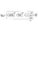
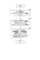
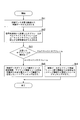
- 7 is a flowchart illustrating an example of the operation of a signal determination unit 211 of the mobile station device 2 in the same embodiment.
- FIG 4 is a flowchart illustrating an example of the operation of a rate dematching unit 236 of the mobile station device 2 in the same embodiment. It is a figure which shows schematic structure of the downlink radio frame in the conventional EUTRA. It is a figure explaining arrangement
- the radio communication system includes a plurality of base station apparatuses 1 and a plurality of mobile station apparatuses 2 that receive signals transmitted by the base station apparatus 1.
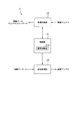
- FIG. 1 is a diagram illustrating a schematic structure of a channel in the wireless communication system of the present embodiment.
- the downlink of radio communication from the base station apparatus 1 to the mobile station apparatus 2 includes a downlink pilot channel, a downlink synchronization channel, a broadcast channel, a downlink control channel, a downlink shared data channel, a control format indicator channel, and a downlink HARQ. (Hybrid Automatic Repeat reQuest) consists of an indicator channel and a multicast channel.
- the uplink of radio communication from the mobile station apparatus 2 to the base station apparatus 1 includes an uplink pilot channel, a random access channel, an uplink control channel, and an uplink shared data channel.
- FIG. 2 is a diagram illustrating a schematic configuration example of a downlink radio frame (radio resource) from the base station apparatus 1 to the mobile station apparatus 2 in the present embodiment.
- the horizontal axis is the time axis
- the vertical axis is the frequency axis.
- the downlink radio frame is a unit such as radio resource allocation to each mobile station apparatus 2 at the time of localized transmission, and a PRB (Physical Resource Block: physical) having a predetermined frequency band and time band. Resource block) pair.
- PRB Physical Resource Block: physical
- one physical resource block PRB pair is composed of two physical resource blocks PRB that are continuous in the time domain.
- the system bandwidth is a communication bandwidth of the base station apparatus 1, and a plurality of physical resource blocks PRB corresponding to the system bandwidth are arranged in the frequency direction in the downlink radio frame.
- time frames time frames
- radio frames made up of 10 subframes.
- a multicast (BMS / Multicast / Multicast / Service) data (first type data) multicast channel (Multicast / Broadcast / Overcast / Single Frequency / Network / Subframe) subframe (first type subframe) is configured.
- unicast subframes (second type subframes) constituting a downlink shared data channel in which information data (second type data) and system information are arranged are time-multiplexed.
- multicast data is multicast data in a broad sense, and is a generic term for broadcast data addressed to an unspecified number of mobile station devices 2 and narrowly defined multicast data addressed to a specified number of mobile station devices 2.
- FIG. 3 is a diagram illustrating a schematic configuration of a unicast subframe in the present embodiment.
- the horizontal axis is a time axis
- the vertical axis is a frequency axis.
- one physical resource block PRB is composed of 12 subcarriers in the frequency domain, and is composed of 7 OFDM symbols in the time domain.
- at least a downlink shared data channel used for transmitting information data and system information and a downlink control channel used for transmitting control data are arranged.
- the downlink pilot channels used for channel estimation of the downlink shared data channel and the downlink control channel are not shown in FIG. In FIG.
- the downlink control channel is arranged in the first, second, and third OFDM symbols of the subframes indicated by hatched squares, and the downlink shared data channel is indicated by other squares that are not hatched.
- the OFDM symbol in which the downlink control channel is arranged varies in subframe units.
- the control format indicator channel indicating the number of OFDM symbols constituting the downlink control channel is arranged at a predetermined frequency position of the first OFDM symbol.
- the downlink control channel is arranged only in the first OFDM symbol, is arranged in the first and second OFDM symbols, or is arranged over the first to third OFDM symbols.
- the downlink HARQ indicator channel is arranged in the OFDM symbol in which the downlink control channel is arranged, that is, frequency-multiplexed with the downlink control channel. Note that the downlink control channel and the downlink shared data channel are not arranged together in the same OFDM symbol.
- At least downlink radio resource allocation information is arranged in the downlink control channel of the unicast subframe. In this embodiment, in addition to the downlink radio resource allocation information, a plurality of uplink radio resource allocation information, transmission power command information Is placed.
- FIG. 4 is a diagram showing a schematic configuration of a multicast subframe in the present embodiment.
- the horizontal axis is the time axis
- the vertical axis is the frequency axis.
- one physical resource block PRB is composed of 12 subcarriers in the frequency domain, and is composed of 6 OFDM symbols in the time domain.
- a slot is composed of 6 OFDM symbols
- a subframe is composed of 2 slots.
- at least a multicast channel used for transmission of multicast data is arranged.
- the downlink pilot channels used for channel estimation of the multicast channel and the downlink control channel are not shown in FIG. In FIG.
- the downlink control channel is arranged in the first and second OFDM symbols of the subframe indicated by hatched squares, and the downlink shared data channel is arranged in the other OFDM symbols indicated by squares without hatching.
- the OFDM symbol in which the downlink control channel is arranged changes in subframe units.
- the number of OFDM symbols constituting the multicast subframe is smaller than the number of OFDM symbols constituting the unicast subframe, but the length of the OFDM symbol in which the multicast channel is arranged is equal to the OFDM length of the unicast subframe.
- the time lengths of the slots of the multicast subframe and the unicast subframe are the same.
- spare samples are arranged between the OFDM symbols of the downlink control channel and the OFDM symbols of the multicast channel in the multicast subframe.
- the control format indicator channel which shows the number of OFDM symbols which comprises a downlink control channel is arrange
- the downlink control channel is arranged only in the first OFDM symbol, or arranged in the first and second OFDM symbols.
- the downlink HARQ indicator channel is arranged in the OFDM symbol in which the downlink control channel is arranged, that is, frequency-multiplexed with the downlink control channel. Note that the downlink control channel and the multicast channel are not arranged together in the same OFDM symbol.
- a plurality of uplink radio resource allocation information and transmission power command information are arranged in the downlink control channel of the multicast subframe.
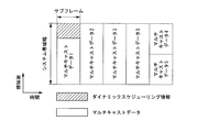
- FIG. 5 is a diagram for explaining dynamic scheduling information in this embodiment.
- the horizontal axis is a time axis
- the vertical axis is a frequency axis.
- Dynamic scheduling information is represented by a hatched square
- multicast data is represented by a hatched square.
- the multicast subframe arrangement pattern is information for designating a subframe in which a multicast subframe can be arranged for a group of subframes within a predetermined period (details will be described later).
- One or a plurality of dynamic scheduling information is arranged within the period of the multicast subframe arrangement pattern, and a data string composed of continuous multicast data among the subframes specified by the multicast subframe arrangement pattern (in the example of FIG. A subframe in which data 1 to 5) are arranged, that is, a subframe to be a multicast subframe.
- the multicast subframe arrangement pattern is input to the base station apparatus 1 from the outside and held.
- the dynamic scheduling information includes, for example, information indicating multicast data 1 and information indicating the first subframe specified by the multicast subframe arrangement pattern in association with each other, information indicating multicast data 2, and multicast
- the information indicating the second subframe specified by the subframe arrangement pattern is stored in association with it, and the other multicast data 3 to 5 are stored in association with the information indicating the subframe in the same manner.
- the information stored in association with the multicast data 1 to 5 stores not only the information indicating the subframe but also the information indicating the size of the multicast data 1 to 5 or the position in the subframe. May be.
- multicast data 1 to 5 indicate continuous multicast data each assigned to one service.
- each of the multicast data 1 to 3 is video data of one video stream service
- each of the multicast data 4 and 5 is audio data of one audio stream service.
- the dynamic scheduling information is multiplexed with multicast data 1 in a subframe.
- the dynamic scheduling information has the following characteristics. (1) A subframe in which one or a plurality of multicast data is arranged. (2) It may be multiplexed with multicast data within a subframe. (3) A plurality of dynamic scheduling information may be included in the period of the multicast subframe arrangement pattern.
- the base station apparatus 1 transmits time-multiplexed multicast subframes in which multicast data is arranged and unicast subframes in which unicast data is arranged.
- the base station apparatus 1 arranges and transmits system information on the downlink shared data channel in the unicast subframe.
- This system information is information on the timing of transmitting a multicast subframe, and includes a multicast subframe arrangement pattern (first type subframe candidate information) that is information input from the outside.
- the base station apparatus 1 transmits dynamic scheduling information indicating a subframe in which one or a plurality of multicast data is arranged among the subframes indicated by the multicast subframe arrangement pattern.
- the base station apparatus 1 informs the subframe as a unicast subframe. Place and send data.
- FIG. 6 is a schematic block diagram showing the configuration of the base station apparatus 1 in the embodiment of the present invention.
- the base station apparatus 1 includes a radio resource control unit 10, a control unit 11, a reception processing unit 12, and a transmission processing unit 13.
- the radio resource control unit 10 performs intermittent transmission / reception cycles with the mobile station apparatus 2, modulation scheme / coding rate, transmission power, radio resource allocation of downlink shared data channel, arrangement of multicast and unicast subframes, downlink It manages the number of OFDM symbols constituting the link control channel, multiplexing of downlink control channels, downlink shared data channels, multicast channels, and the like.
- the radio resource control unit 10 outputs a control signal instructing these management contents to the control unit 11 and notifies the mobile station device 2 of control data, system information, or dynamic scheduling information through the control unit 11 and the transmission processing unit 13. .
- the radio resource control unit 10 receives a multicast subframe arrangement pattern from the outside, and determines each subframe based on the multicast subframe arrangement pattern and the amount of multicast data to be transmitted. The type of multicast subframe or unicast subframe is determined.
- the control unit 11 outputs control signals to the transmission processing unit 13 and the reception processing unit 12 in order to control the transmission processing unit 13 and the reception processing unit 12 based on the control signal input from the radio resource control unit 10. .
- the control unit 11 sets the modulation scheme of the transmission / reception signal, the coding rate setting, the setting of the number of OFDM symbols constituting the downlink control channel, the allocation setting of each channel to the resource element, and the multicast subframe corresponding to the multicast subframe allocation pattern. Control such as arrangement of frames and unicast subframes, generation of downlink pilot channels, and the like is performed on the transmission processing unit 13 and the reception processing unit 12.
- the control unit 11 generates control data to be arranged in the downlink control channel, and instructs the transmission processing unit 13 to perform transmission.
- control unit 11 generates system information to be arranged in the downlink shared data channel such as a multicast subframe arrangement pattern, and instructs the transmission processing unit 13 to perform transmission as data together with the information data. Further, the control unit 11 generates information to be arranged on the multicast channel and instructs the transmission processing unit 13 to transmit.
- the transmission processing unit 13 Based on the input from the control unit 11, the transmission processing unit 13 generates a downlink control channel, a downlink shared data channel, a multicast channel, a downlink pilot channel, and a control format indicator channel, and converts each channel into a downlink radio frame. Multiplexed and transmitted to each mobile station apparatus 2 via a plurality of, for example, four transmission antennas. In addition, since it is not directly related to the present invention, the description of the processing regarding the broadcast channel, the downlink synchronization channel, and the downlink HARQ indicator channel is omitted.
- the reception processing unit 12 Based on the input from the control unit 11, the reception processing unit 12 receives the uplink control channel, the uplink shared data channel, the uplink pilot channel, and the random access channel transmitted by each mobile station apparatus 2 via the reception antenna. Do. In addition, since it is not directly related to the present invention, description of processing related to the uplink is omitted.
- FIG. 7 is a schematic block diagram illustrating an internal configuration of the transmission processing unit 13 of the base station apparatus 1 in the present embodiment.
- the transmission processing unit 13 of the base station apparatus 1 includes a plurality of downlink shared data channel processing units 31, a multicast channel processing unit 32, a plurality of downlink control channel processing units 33, and a reference signal (downlink pilot channel) generation.
- the plurality of downlink shared data channel processing units 31, the plurality of downlink control channel processing units 33, and the per-antenna transmission processing unit (transmitting unit) 37 for each transmission antenna have the same configuration and function. I will explain on behalf of one.
- the downlink shared data channel processing unit 31 performs processing on the downlink shared data channel for information data input from the outside and system information input from the control unit 11. That is, each downlink shared data channel processing unit 31 receives information data addressed to any one of the mobile station apparatuses 2, performs turbo coding and data modulation, and generates a signal addressed to the mobile station apparatus 2. In response to system information such as a multicast subframe arrangement pattern, turbo coding and data modulation are performed, and a signal addressed to an unspecified number of mobile station apparatuses 2 is generated.
- the downlink shared data channel processing unit 31 includes a turbo coding unit 311 and a data modulation unit 312.
- the multicast channel processing unit (scheduling information signal generation unit) 32 performs multicast channel processing on multicast data input from the outside and dynamic scheduling information input from the control unit 11, that is, the multicast channel processing unit 32 performs multicast data processing. In response to the dynamic scheduling information, turbo coding and data modulation are performed to generate a signal addressed to an unspecified number of mobile station apparatuses 2.
- the multicast channel processing unit 32 includes a turbo coding unit 321 and a data modulation unit 322.
- the downlink control channel processing unit (control signal generation unit) 33 performs processing of the downlink control channel on the control data input from the control unit 11, that is, each downlink control channel processing unit 33 is one of the control data.
- Control data addressed to two mobile station apparatuses 2 receiving downlink radio resource allocation information or uplink radio resource allocation information addressed to the mobile station apparatus 2, performing encoding and QPSK modulation, Or control data addressed to a plurality of mobile station apparatuses 2, receiving transmission power command information addressed to the unspecified number of mobile station apparatuses 2, encoding and QPSK (Quadrature Phase Shift Keying; 4 phase (Phase shift keying) modulation is performed to generate a signal of the control data.
- the modulation method is not limited to QPSK modulation.
- the downlink control channel processing unit 33 generates a control data signal including items according to the type of subframe in which the signal generated by the processing unit is arranged.
- the items of control data arranged in the unicast subframe are uplink radio resource allocation information, downlink radio resource allocation information, transmission power command information, and the items of control data arranged in the multicast subframe are: Uplink radio resource allocation information and transmission power command information.
- the downlink control channel processing unit 33 includes a coding unit 331 and a QPSK modulation unit 332.
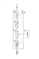
- FIG. 8 is a block diagram illustrating an internal configuration of the encoding unit 331 of the downlink control channel processing unit 33.
- the coding unit 331 of the downlink control channel processing unit 33 includes an error detection code multiplexing unit 333, a convolution coding unit 334, and a rate matching unit 335.
- the encoding unit 331 of the downlink control channel processing unit 33 performs encoding processing on the control data input from the control unit 11.
- the error detection code multiplexing unit 333 multiplexes an error detection code generated using a predetermined generation polynomial on the control data
- the convolution coding unit 334 includes The control data in which the error detection code is multiplexed is convolutionally encoded, and the rate matching unit 335 repeats the convolutionally encoded control data and performs a thinning process so as to obtain a predetermined resource element size.
- the control data signal is encoded to a corresponding length.
- the predetermined sizes of the four resource elements are 36 resource elements, 72 resource elements, 144 resource elements, and 288 resource elements.
- the length corresponding to the size of the resource element is the length when QPSK modulation is performed, that is, the length of 2 bits for one resource element.
- the multiplexing unit 36 arranges the information data and the system information signal generated by the downlink shared data channel processing unit 31 in a unicast subframe, and the multicast data and the dynamic scheduling information signal generated by the multicast channel processing unit 32.
- the control data signal generated by the downlink control channel processing unit 33 is arranged in the unicast subframe and the multicast subframe.
- the transmission processing unit 37 for each transmission antenna transmits the signal of the multiplexing result multiplexed by the multiplexing unit 36 for each transmission antenna via each transmission antenna.
- the transmission processing unit 37 for each transmission antenna includes an IFFT (Inverse Fast Fourier Transform) unit 371, a GI (Guard Interval) insertion unit 372, a D / A (digital / analog conversion) unit 373, And a transmission RF (Radio Frequency) unit 374.
- Each of the plurality of downlink shared data channel processing units 31 transmits information data input from the outside and system information input from the control unit 11 (hereinafter, information data and system information together are referred to as “data”) to OFDM Performs baseband processing for transmission in the system.
- the turbo coding unit 311 performs error correction coding using a turbo code for increasing the error resistance of the input data in accordance with the coding rate instruction from the control unit 11.
- the data modulation section 312 is a modulation scheme instructed by the control section 11 among modulation schemes such as QPSK, 16QAM (16 Quadrature Amplitude Modulation), and 64 QAM (64 Quadrature Amplitude Modulation).
- the data that has been subjected to error correction coding by the turbo coding unit 311 is modulated.
- the multicast channel processing unit 32 performs baseband processing for transmitting multicast data input from the outside and dynamic scheduling information input from the control unit 11 by the OFDM method.
- the turbo coding unit 321 performs error correction coding using a turbo code to increase error resistance of the input multicast data and dynamic scheduling information in accordance with the coding rate instruction from the control unit 11.
- the data modulation unit 322 is a modulation scheme instructed by the control unit 11 among modulation schemes such as QPSK, 16QAM (16 Quadrature Amplitude Modulation), and 64 QAM (64 Quadrature Amplitude Modulation). Then, the multicast data and the dynamic scheduling information that have been error correction encoded by the turbo encoder 321 are modulated.
- Each of the plurality of downlink control channel processing units 33 performs baseband processing for transmitting control data in the OFDM scheme.
- the encoding unit 331 multiplexes the control data input from the control unit 11 with the error detection code unit 333 for detecting the control data and the error, and the convolutional encoding unit 334 increases the error resistance of the control data.
- error correction coding using a convolutional code is performed, and the rate matching unit 335 performs repetition or decimation to match the size when the control data is multiplexed on the downlink control channel by the multiplexing unit 36.
- the QPSK modulation unit 332 modulates the control data encoded by the encoding unit 331 using the QPSK modulation method.
- the reference signal generation unit 34 Based on the control signal indicating the type of each subframe from the control unit 11, the reference signal generation unit 34 transmits a downlink control channel or downlink shared data transmitted by each transmission antenna of the base station apparatus 1 using the downlink pilot channel. A reference signal for a channel or the like and a reference signal for a multicast channel are generated. Based on the control signal from the control unit 11, the control format indicator signal generation unit 35 generates a control format indicator signal for transmitting information indicating the OFDM symbols constituting the downlink control channel through the control format indicator channel.
- the multiplexing unit 36 Based on the control signal from the control unit 11, the multiplexing unit 36 outputs a transmission signal of data addressed to each mobile station apparatus 2 processed by the downlink shared data channel processing unit 31 such as encoding and modulation, Multicast data transmission signal addressed to the mobile station apparatus 2 that has been subjected to the encoding and modulation processing output from the multicast channel processing section 32 and the processed control such as encoding and modulation output from the downlink control channel processing section 33
- a data transmission signal, a control format indicator signal, and a reference signal are arranged in a resource element for each transmission antenna.
- the multiplexing unit 36 does not multiplex the transmission signal generated by the downlink shared data channel processing unit 31 and the transmission signal generated by the multicast channel processing unit 32 in the same subframe. That is, the multiplexing unit 36 arranges the transmission signal generated by the downlink shared data channel processing unit 31 in the resource element of the unicast subframe, and arranges the transmission signal generated by the multicast channel processing unit 32 in the resource element of the multicast subframe. To do.
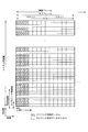
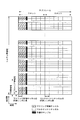
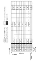
- FIG. 9 is a diagram for explaining a combination of a multicast subframe arrangement pattern and dynamic scheduling information in the present embodiment. That is, it is a diagram illustrating a subframe in which the position of a subframe in which multicast data is transmitted is not indicated by dynamic scheduling information in a plurality of subframes indicated by the multicast subframe arrangement pattern.
- the horizontal axis is the time axis
- the vertical axis is the frequency axis.
- dynamic scheduling information and multicast data to be arranged in the multicast subframe and information data to be arranged in the unicast subframe are shown, and other data arranged in each subframe is not shown. .
- the dynamic scheduling information is represented by a hatched square (first subframe specified by the multicast subframe arrangement pattern), and the multicast data is represented by a thick square (1 specified by the multicast subframe arrangement pattern). ⁇ 5th subframe), the information data is represented by a rectangular box (subframe not specified in the multicast subframe arrangement pattern), and the subframe that is specified in the multicast subframe arrangement pattern but does not transmit multicast data
- the frame is represented by a square with a cross (sixth to seventh subframes specified by the multicast subframe arrangement pattern).
- the multicast subframe arrangement pattern indicates the second, third, seventh, ninth, tenth, eleventh and thirteenth subframes. However, since the dynamic scheduling information indicates only the second, third, seventh, ninth and tenth subframes, multicast data is not arranged in the eleventh and thirteenth subframes.
- the multiplexing unit 36 can arrange the data transmission signal output by the downlink shared data channel processing unit 31 in such a subframe.
- the multiplexing unit 36 arranges uplink radio resource allocation information and transmission power command information in the subframes indicated by the dynamic scheduling information, that is, the multicast subframes. Further, the multiplexing unit 36, in the subframe indicated by the multicast subframe arrangement pattern, a subframe that arranges the transmission signal of the data output by the downlink shared data channel processing unit 31 in the subframe that is not indicated by the dynamic scheduling information, That is, downlink radio resource allocation information, uplink radio resource allocation information, and transmission power command information are arranged in the unicast subframe.
- the IFFT unit 371 performs OFDM inverse modulation by performing a fast inverse Fourier transform on the signal input from the multiplexing unit 36.
- the GI insertion unit 372 adds a guard interval to the signal that has been OFDM-modulated by the IFFT unit 371 based on the control signal from the control unit 11 to form a symbol in the OFDM scheme.
- This OFDM symbol is a baseband digital signal.
- the guard interval is obtained by a known method of duplicating a part of the beginning or end of a symbol to be transmitted.
- the GI insertion part 372 multiplexes a spare sample (FIG. 4) in the case of a multicast subframe.
- the D / A unit 373 converts the baseband digital signal input from the GI insertion unit 372 into an analog signal.
- the transmission RF unit 374 generates an in-phase component and a quadrature component of the intermediate frequency from the analog signal input from the D / A unit 373, removes excess frequency components for the intermediate frequency band, and outputs the intermediate frequency signal to a high frequency
- the signal is converted (up-converted) into the above signal, the excess frequency component is removed, the power is amplified, and the signal is output to the corresponding transmitting antenna.
- the base station apparatus 1 includes the transmission processing units 37 for each antenna by the number of transmission antennas used for transmission, that is, five in this embodiment, and the transmission processing unit 37 for each antenna is output by the multiplexing unit 36. Among the signals for each transmission antenna, the signal for the corresponding transmission antenna is processed.
- the mobile station apparatus 2 of the present embodiment receives a signal addressed to itself from the subframe transmitted by the base station apparatus 1.
- the mobile station apparatus 2 indicates that the subframe indicated by the dynamic scheduling information as including multicast data is the multicast subframe.
- the subframes that are not indicated as including multicast data in the dynamic scheduling information are determined to be unicast subframes.
- the mobile station apparatus 2 determines a method for decoding the downlink control channel when it is determined that the subframe indicated by the multicast subframe arrangement pattern is a unicast subframe and when it is determined that the subframe is a multicast subframe. By switching, the processing load is suppressed.
- FIG. 10 is a schematic block diagram showing the configuration of the mobile station apparatus 2 in the present embodiment.
- the mobile station device 2 includes a control unit 21, a reception processing unit 22, and a transmission processing unit 23.
- the reception processing unit 22 performs reception processing on the downlink control channel, downlink shared data channel, multicast channel, downlink pilot channel, and control format indicator channel received from the base station apparatus 1 via the reception antenna.
- the reception processing unit 22 uses the control data notified using the downlink control channel, the system information notified using the downlink shared data channel and the broadcast channel, and the control format notified using the control format indicator channel.
- the indicator signal and the dynamic scheduling information notified using the multicast channel are output to the control unit 21.
- the reception processing unit 22 outputs the information data notified using the downlink shared data channel and the multicast data notified using the multicast channel to the outside.
- the control unit 21 is notified using the control data notified from the base station apparatus 1 using the downlink control channel, the system information notified using the downlink shared data channel and the broadcast channel, and the control format indicator channel.
- the transmission processing unit 23 and the reception processing unit 22 are controlled based on the control format indicator signal and the dynamic scheduling information notified using the multicast channel.
- control unit 21 includes a signal determination unit 211.
- the signal determination unit (frame type determination unit) 211 determines whether the received subframe is a multicast subframe or a unicast subframe based on the dynamic scheduling information input from the reception processing unit 22 and the multicast subframe arrangement pattern.
- the reception processing unit 22 is instructed to remove a guard interval, a downlink control channel decoding method, and a demultiplexing method.
- the transmission processing unit 23 transmits the information data input from the outside and the control data input from the control unit 21 based on the input from the control unit 21, an uplink control channel, an uplink shared data channel, an uplink pilot channel And via a transmit antenna using a random access channel.
- the details of the processing related to the uplink by the transmission processing unit 23 are omitted.
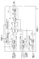
- FIG. 11 is a schematic block diagram showing an internal configuration of the reception processing unit 22 of the mobile station device 2 in the present embodiment.
- the reception processing unit 22 of the mobile station apparatus 2 includes a reception RF (Radio Frequency) unit 221, an A / D (Analogue / Digital) unit 222, and a GI (Guard Interval) removal unit.
- a reception RF Radio Frequency
- a / D Analogue / Digital
- GI Guard Interval
- the reception RF unit 221, the A / D unit 222, the GI removal unit 223, and the FFT unit 224 function as a reception unit that receives a signal transmitted from the base station apparatus 1.
- the reception RF unit 221 amplifies the signal received via the reception antenna, converts it to an intermediate frequency (down-conversion), removes unnecessary frequency components, and controls the amplification level so that the signal level is properly maintained. Then, quadrature demodulation is performed based on the in-phase component and the quadrature component of the received signal.
- the A / D unit 222 converts the analog signal orthogonally demodulated by the reception RF unit 221 into a digital signal.
- the GI removal unit 223 removes a portion corresponding to the guard interval from the digital signal output from the A / D unit 222 based on an instruction from the control unit 21.
- the FFT unit 224 performs fast Fourier transform on the signal input from the GI removal unit 223, and performs OFDM demodulation.
- the demultiplexing unit 225 Based on an instruction from the control unit 21, the demultiplexing unit 225 performs a Fourier transform by the FFT unit 224, that is, a downlink pilot channel, a control format indicator channel, a downlink shared data channel, from a received signal demodulated by the OFDM method, A multicast channel and a downlink control channel are extracted from the allocated resource elements and output.
- the demultiplexing unit 225 extracts the downlink pilot channel and the control format indicator channel having a fixed arrangement, outputs the downlink pilot channel to the propagation path estimation unit 226, and the control format indicator channel is propagated. Output to the path compensation unit 227. Furthermore, the demultiplexing unit 225 receives the radio resource determined by the control unit 21 based on the control format indicator signal included in the control format indicator channel input to the control unit 21 and output to the propagation path compensation unit 227 previously. A downlink control channel including control data such as allocation information is extracted and output to the propagation path compensation unit 229.
- the demultiplexing unit 225 extracts the downlink shared data channel based on the radio resource allocation information included in the downlink control channel that is input via the control unit 21 and previously output to the propagation path compensation unit 229. To the propagation path compensation unit 228.
- the control unit 21 to which the multicast subframe arrangement pattern included in the system information of the downlink shared data channel and the dynamic scheduling information included in the multicast channel of the subframe currently received or received in the past is input.
- the multicast channel is extracted based on the control signal input from the signal determination unit 211 and output to the propagation path compensation unit 228.
- the propagation path estimation unit 226 estimates the propagation path variation for each transmission antenna of the base station apparatus 1 based on the reception result of the known reference signal arranged in the downlink pilot channel separated by the demultiplexing unit 225, and the propagation path Outputs compensation value. Based on the propagation path fluctuation compensation value from the propagation path estimation section 226, the propagation path compensation section 227 compensates for the propagation path fluctuation of the control format indicator channel signal input from the demultiplexing section 225.
- the control format indicator detection unit 230 is a control format indicator signal indicating the number of OFDM symbols constituting the downlink control channel from the signal arranged in the control format indicator channel for which propagation path fluctuation compensation has been performed by the propagation path compensation unit 227. Is output to the control unit 21.
- the propagation path compensation section 228 compensates for propagation path fluctuation of the downlink shared data channel and multicast channel signals input from the demultiplexing section 225.
- the data demodulator 231 demodulates the downlink shared data channel and the multicast channel that have been compensated for propagation path fluctuations by the propagation path compensator 228. This demodulation is performed in accordance with the modulation scheme used in the data modulation sections 312 and 322 of the base station apparatus 1, and the modulation scheme of the downlink shared data channel is determined based on information included in the downlink control channel.
- the control method is instructed from the control unit 21 based on the system information of the downlink shared data channel and the information included in the multicast channel.
- the turbo decoding unit 232 decodes the downlink shared data channel and multicast channel demodulated by the data demodulation unit 231. That is, the turbo decoding unit (scheduling information detection unit) 232 detects dynamic scheduling information arranged in the multicast channel from the received signal. System information included in the downlink shared data channel decoded by the turbo decoding unit 232 is input to the control unit 21. This decoding is performed corresponding to the coding rate used in the turbo coding unit of the base station apparatus 1, and the coding rate of the downlink shared data channel is determined based on information included in the downlink control channel. The coding rate of the multicast channel is instructed from the control unit 21 based on the system information of the downlink shared data channel and the information included in the multicast channel.
- the propagation path compensation section 229 compensates for propagation path fluctuation of the downlink control channel signal input from the demultiplexing section 225.
- the QPSK demodulator 233 performs QPSK demodulation of the downlink control channel in which propagation path fluctuation is compensated by the propagation path compensation unit 226.
- the decoding unit (control data detection unit) 234 decodes the downlink control channel demodulated by the QPSK demodulation unit 233. That is, the decoding unit 234 performs control data detection processing for items corresponding to the types indicated by the determination result of the signal determination unit 211 for each subframe of the received signal.
- the data size corresponding to the item corresponding to the type indicated by the determination result is used. Specifically, in rate dematching when performing detection processing, rate dematching is performed so that the rate dematching result has this data size.
- Control data configured in the downlink control channel decoded by the decoding unit 234 is input to the control unit 21. Details of the decoding unit 234 will be described later.
- the control unit 21 outputs a control signal to the data demodulation unit 231 based on information on the modulation scheme in the control data, and outputs a control signal to the turbo decoding unit 232 based on information on the coding rate in the control data. Further, the control unit 21 outputs a control signal to the demultiplexing unit 225 so as to extract the downlink control channel of the mobile station apparatus 2 from the allocated resource elements based on the control format indicator signal. In addition, when the control data input from the decoding unit 234 is downlink radio resource allocation information, the control unit 21 arranges the downlink shared data channel of the mobile station apparatus 2 based on the downlink radio resource allocation information. A control signal is output to the demultiplexing unit 225 so as to be extracted from the resource element.
- control unit 21 when the control data input from the decoding unit 234 is uplink radio resource allocation information, the control unit 21 causes the transmission processing unit 23 to transmit an uplink shared data channel based on the uplink radio resource allocation information. Output a control signal.
- control unit 21 when the control data input from the decoding unit 234 is transmission power command information, the control unit 21 sets the uplink shared data channel or the transmission power of the uplink control channel based on the transmission power command information. A control signal is output to the transmission processing unit 23.
- the signal determination unit (frame type determination unit) 211 holds a multicast subframe arrangement pattern in the system information arranged in the downlink shared data channel input from the turbo decoding unit 232, and the multicast subframe arrangement Based on the pattern and the dynamic scheduling information arranged in the multicast channel input from the turbo decoding unit 232, the type of each received subframe is determined.
- the signal determination unit 211 recognizes a subframe designated as being able to place a multicast subframe based on the held multicast subframe placement pattern, and sets the type of the subframe not designated as a unicast subframe. Judge as a frame. Further, the signal determination unit 211 responds to the multicast data by the dynamic scheduling information arranged in the multicast channel input from the turbo decoding unit 232 among the subframes designated to be able to arrange the previously recognized multicast subframe. The type of the attached subframe is determined to be a multicast subframe. In addition, the signal determination unit 211 determines the type of the subframe that is not associated with the multicast data by the dynamic scheduling information as the unicast subframe among the subframes that are designated as being capable of arranging the previously recognized multicast subframe. judge.
- the signal determination unit 211 instructs the propagation path estimation unit 226, the propagation path compensation unit 228, the data demodulation unit 231 and the turbo decoding unit 232 with a control signal to perform processing according to the type of the received subframe. To do.
- FIG. 12 is a block diagram showing an internal configuration of the decoding unit 234 of the mobile station apparatus 1.
- the decoding unit 234 includes a control data demultiplexing unit 235, a rate dematching unit 236, a Viterbi decoder unit 237, and an error detection unit 238.
- the control data demultiplexing unit 235 displays the QPSK demodulation result (bit string) of the resource element in which the control data addressed to the mobile station apparatus 2 may be arranged as a bit string for every 36 resource elements, a bit string for every 72 resource elements,
- the four bit patterns for each 144 resource elements and the bit strings for each 288 resource element are separated into control data bit strings and output to the rate dematching unit 236.
- the bit string of the control data input from is rate-dematched and output to the Viterbi decoder unit 237. That is, when the signal determining unit 211 determines that the subframe indicated by the multicast subframe arrangement pattern is a multicast subframe, the downlink data resource allocation information is not included in the control data. Instructs the rate dematching unit 236 with a control signal so as to perform rate dematching assuming that the control data input from the control data demultiplexing unit 235 is control data other than downlink radio resource allocation information.
- the control data demultiplexing unit 235 determines the length of the downlink radio resource allocation information as a result of rate dematching for the subframe.
- the rate dematching using the rate matching pattern is not performed. Therefore, there is an effect that the processing load for detecting the control data can be suppressed.
- the signal determination unit 211 determines that the subframe indicated by the multicast subframe arrangement pattern is a unicast subframe, the signal determination unit 211 transmits the control data input from the control data demultiplexing unit 235 to the downlink radio.
- the rate dematching unit 236 is instructed by a control signal so as to perform rate dematching assuming resource allocation information, uplink radio resource allocation information, or transmission power command information.
- the Viterbi decoder unit 237 performs convolution decoding on the control data input from the rate dematching unit 236 and outputs the decoding result to the error detection unit 238.
- the error detection unit 238 extracts an error detection code multiplexed in the control data input from the Viterbi decoder unit 237 and performs error detection. When an error is detected, the error detection unit 238 performs rate dematching with a resource element that has not been tried yet.
- the control data demultiplexing unit 235 is instructed by a control signal so as to perform a decoding process in combination with the data length), and if no error is detected, the control data is output to the control unit 21 and is still being tested.
- the control data demultiplexing unit 235 is instructed to perform no decoding process.
- FIG. 13 is a flowchart illustrating an example of the operation of the signal determination unit 211 of the mobile station device 2.
- the signal determination unit 211 receives the multicast subframe arrangement pattern and the dynamic scheduling information from the turbo decoding unit 232 (Sa1), and then the signal determination unit 232 receives the received subframe from the multicast subframe arrangement pattern and the dynamic scheduling information. Is a multicast subframe or a unicast subframe (Sa2).
- the signal determination unit 211 sends the received subframe type (multicast subframe or unicast) to the rate dematching unit 236, the channel estimation unit 226, the channel compensation unit 228, the data demodulation unit 231, and the turbo decoding unit 231.
- a different instruction is given by the control signal so as to perform processing according to (subframe) (Sa3).
- FIG. 14 is a flowchart for explaining an example of the operation of the rate dematching unit 236 of the mobile station apparatus 2.
- Control data is input from the control data demultiplexing unit 235 to the rate dematching unit 236 (Sb1).
- a control signal indicating whether the subframe received from the signal determination unit 211 is a multicast subframe or a unicast subframe is input to the rate dematching unit 236 (Sb2).
- the rate dematching unit 236 assumes that the control data is uplink radio resource allocation information or transmission power command information. The rate dematching is performed (Sb4).
- the rate dematching unit 236 transmits the control data as downlink radio resource allocation information, uplink radio Rate dematching that assumes resource allocation information or transmission power command information is performed (Sb5).
- the rate dematching unit 236 of the decoding unit 234 detects a rate dematching process for detecting control data of an item corresponding to the type indicated by the determination result of the subframe type by the signal determination unit 211. As a result, a remarkable effect of suppressing the processing load for detecting the control data is obtained.
- the program that operates in the mobile station apparatus 2 related to the present invention is a program (a program that causes a computer to function) that controls a CPU (Central Processing Unit) or the like so as to realize the functions of the above-described embodiments related to the present invention. is there. Information handled by these devices is temporarily stored in RAM (Random Access Memory) during the processing, and then stored in various ROMs such as Flash ROM (Read Only Memory) and HDD (Hard Disk Drive). Reading, correction, and writing are performed by the CPU as necessary.
- RAM Random Access Memory
- ROMs Read Only Memory
- HDD Hard Disk Drive
- the “computer system” includes an OS and hardware such as peripheral devices.
- the “computer-readable recording medium” means a storage device such as a flexible disk, a magneto-optical disk, a portable medium such as a ROM and a CD-ROM, and a hard disk incorporated in a computer system. Furthermore, the “computer-readable recording medium” dynamically holds a program for a short time like a communication line when transmitting a program via a network such as the Internet or a communication line such as a telephone line. In this case, a volatile memory in a computer system serving as a server or a client in that case, and a program that holds a program for a certain period of time are also included.
- the program may be a program for realizing a part of the functions described above, and may be a program capable of realizing the functions described above in combination with a program already recorded in a computer system.
- the present invention is suitable for use in a mobile communication system in which a mobile phone terminal is a mobile station device, but is not limited thereto.
Landscapes
- Engineering & Computer Science (AREA)
- Signal Processing (AREA)
- Computer Networks & Wireless Communication (AREA)
- Mobile Radio Communication Systems (AREA)
Abstract
Priority Applications (5)
| Application Number | Priority Date | Filing Date | Title |
|---|---|---|---|
| CN200980123647.0A CN102067695B (zh) | 2008-06-24 | 2009-06-23 | 无线通信系统、移动站装置以及无线接收方法 |
| EP12003766.8A EP2501194B1 (fr) | 2008-06-24 | 2009-06-23 | Système de communication sans fil, dispositif de station mobile et procédé de réception sans fil |
| JP2010518021A JP5093912B2 (ja) | 2008-06-24 | 2009-06-23 | 無線通信システム、移動局装置および無線受信方法 |
| US12/997,894 US9088997B2 (en) | 2008-06-24 | 2009-06-23 | Wireless communication system, mobile station device, and wireless reception method |
| EP09770153A EP2293635A4 (fr) | 2008-06-24 | 2009-06-23 | Système de radiocommunication, dispositif de station mobile et procédé de réception radio |
Applications Claiming Priority (2)
| Application Number | Priority Date | Filing Date | Title |
|---|---|---|---|
| JP2008165110 | 2008-06-24 | ||
| JP2008-165110 | 2008-06-24 |
Publications (1)
| Publication Number | Publication Date |
|---|---|
| WO2009157443A1 true WO2009157443A1 (fr) | 2009-12-30 |
Family
ID=41444509
Family Applications (1)
| Application Number | Title | Priority Date | Filing Date |
|---|---|---|---|
| PCT/JP2009/061404 Ceased WO2009157443A1 (fr) | 2008-06-24 | 2009-06-23 | Système de radiocommunication, dispositif de station mobile et procédé de réception radio |
Country Status (5)
| Country | Link |
|---|---|
| US (1) | US9088997B2 (fr) |
| EP (2) | EP2501194B1 (fr) |
| JP (2) | JP5093912B2 (fr) |
| CN (1) | CN102067695B (fr) |
| WO (1) | WO2009157443A1 (fr) |
Cited By (6)
| Publication number | Priority date | Publication date | Assignee | Title |
|---|---|---|---|---|
| JP2012525729A (ja) * | 2009-04-28 | 2012-10-22 | アルカテル−ルーセント | 無線ネットワーク内でのブロードキャストおよび/またはマルチキャストの通信方法およびデバイス |
| JP2012525726A (ja) * | 2009-04-28 | 2012-10-22 | アルカテル−ルーセント | Mbsfn送信のために無線リソースを動的にディスパッチする方法、mce、および基地局 |
| CN102763358A (zh) * | 2010-01-22 | 2012-10-31 | 夏普株式会社 | 发送装置、接收装置、通信系统以及通信方法 |
| KR20140016366A (ko) * | 2011-05-05 | 2014-02-07 | 퀄컴 인코포레이티드 | 무선 통신 시스템 내의 mbsfn 환경에서 예비된 셀들 및 사용자 장비들의 관리 |
| JP2019507991A (ja) * | 2016-03-07 | 2019-03-22 | クゥアルコム・インコーポレイテッドQualcomm Incorporated | スタンドアロンlteブロードキャストのための同期 |
| JPWO2022130630A1 (fr) * | 2020-12-18 | 2022-06-23 |
Families Citing this family (25)
| Publication number | Priority date | Publication date | Assignee | Title |
|---|---|---|---|---|
| AU2007200185A1 (en) * | 2006-02-08 | 2007-08-23 | Nec Australia Pty Ltd | Delivery of multicast and uni-cast services in an OFDMA system |
| US7834807B2 (en) * | 2007-05-21 | 2010-11-16 | Spatial Digital Systems, Inc. | Retro-directive ground-terminal antenna for communication with geostationary satellites in slightly inclined orbits |
| KR101649493B1 (ko) * | 2008-09-18 | 2016-08-19 | 삼성전자주식회사 | Crc 길이의 가상 확장 방법 및 장치 |
| US8743799B2 (en) | 2010-06-24 | 2014-06-03 | Nokia Siemens Networks Oy | Change of rate matching modes in presence of channel state information reference signal transmission |
| JP5432210B2 (ja) * | 2011-05-02 | 2014-03-05 | 株式会社Nttドコモ | ユーザ端末、無線基地局、下り制御チャネル受信方法及び移動通信システム |
| WO2012171465A1 (fr) * | 2011-06-14 | 2012-12-20 | 华为技术有限公司 | Procédé et dispositif de communication dans un système à duplexage par répartition temporelle |
| DK2737757T3 (en) * | 2011-07-28 | 2017-05-08 | Nokia Technologies Oy | APPARATUS AND PROCEDURE FOR UPLINK POWER CONTROL FOR VARIABLE INTERFERENCE CONDITIONS |
| KR101857019B1 (ko) * | 2011-08-29 | 2018-05-14 | 삼성전자주식회사 | 디바이스 간 직접 통신을 수행하는 시스템에서 브로드캐스트 방법 및 장치 |
| JP5832914B2 (ja) * | 2012-01-27 | 2015-12-16 | シャープ株式会社 | 通信システム、移動局装置、基地局装置、通信方法および集積回路 |
| US20130304938A1 (en) * | 2012-05-11 | 2013-11-14 | Qualcomm Incorporated | Minimizing interference in low latency and high bandwidth communications |
| EP3032862B1 (fr) | 2013-08-07 | 2019-02-27 | Huawei Technologies Co., Ltd. | Procédé et dispositif de transmission et de réception d'informations |
| US9369241B2 (en) * | 2014-02-18 | 2016-06-14 | Huawei Technologies Co., Ltd. | HARQ frame data structure and method of transmitting and receiving with HARQ in systems using blind detection |
| CN107113745B (zh) * | 2014-12-11 | 2020-09-08 | 意大利电信股份公司 | 用于管理移动蜂窝网络中的数据传输功率的方法 |
| US11032780B2 (en) * | 2015-09-03 | 2021-06-08 | Qualcomm Incorporated | Power control in wireless networks |
| US11831584B2 (en) * | 2015-12-15 | 2023-11-28 | Qualcomm Incorporated | Techniques for indicating a dynamic subframe type |
| US9960885B2 (en) * | 2016-02-16 | 2018-05-01 | Samsung Electronics Co., Ltd | Method and apparatus for hybrid automatic repeat requests (HARQ) processing for retransmissions with unknown data length |
| KR102458067B1 (ko) * | 2016-03-30 | 2022-10-24 | 삼성전자 주식회사 | 이동 통신 시스템에서의 신호 전송 방법 및 장치 |
| EP3282797A1 (fr) * | 2016-08-09 | 2018-02-14 | Alcatel Lucent | Procédés pour un système de communication mobile, une station de base et une station mobile, système de communication mobile, station de base et station mobile |
| WO2018061159A1 (fr) * | 2016-09-29 | 2018-04-05 | 富士通株式会社 | Dispositif de station de base, dispositif terminal et procédé d'émission |
| JP2020017781A (ja) * | 2016-11-14 | 2020-01-30 | 株式会社Nttドコモ | 通信装置、及びデータ受信方法 |
| JP6794389B2 (ja) * | 2018-02-21 | 2020-12-02 | 華為技術有限公司Huawei Technologies Co.,Ltd. | 情報送信及び受信方法及びデバイス |
| JP2020182191A (ja) * | 2019-04-26 | 2020-11-05 | 日本電気株式会社 | 無線伝送システム、無線伝送装置、無線伝送方法及び無線伝送プログラム |
| US11558825B2 (en) * | 2020-08-03 | 2023-01-17 | Samsung Electronics Co., Ltd | Method and apparatus for uplink transmission in a wireless communication system |
| CN114070492B (zh) * | 2020-08-03 | 2026-04-28 | 北京三星通信技术研究有限公司 | 上行传输方法和相应设备 |
| KR20230056696A (ko) * | 2020-08-05 | 2023-04-27 | 프라운호퍼 게젤샤프트 쭈르 푀르데룽 데어 안겐반텐 포르슝 에. 베. | 데이터 통신 장치, 데이터 통신 방법, 통신 장치, 및 공유 데이터를 사용한 통신 방법 |
Citations (3)
| Publication number | Priority date | Publication date | Assignee | Title |
|---|---|---|---|---|
| JP2007214822A (ja) * | 2006-02-08 | 2007-08-23 | Ntt Docomo Inc | 送信装置及び送信方法 |
| JP2007221277A (ja) * | 2006-02-14 | 2007-08-30 | Ntt Docomo Inc | 送信装置及び送信方法 |
| JP2008165110A (ja) | 2007-01-04 | 2008-07-17 | Ricoh Co Ltd | 画像形成装置の排気機構 |
Family Cites Families (25)
| Publication number | Priority date | Publication date | Assignee | Title |
|---|---|---|---|---|
| US7599334B2 (en) * | 2001-10-15 | 2009-10-06 | Qualcomm Incorporated | Method and apparatus for processing shared sub-packets in a communication system |
| US8644200B2 (en) * | 2004-10-22 | 2014-02-04 | Qualcomm Incorporated | Time multiplexing of unicast and multicast signals on a downlink carrier frequency in a wireless communication system |
| CN1941687A (zh) * | 2005-09-29 | 2007-04-04 | 华为技术有限公司 | 广播业务信道与非广播业务信道的复用方法 |
| KR101333918B1 (ko) * | 2006-01-05 | 2013-11-27 | 엘지전자 주식회사 | 이동 통신 시스템의 점-대-다 서비스 통신 |
| US20090257371A1 (en) * | 2006-05-01 | 2009-10-15 | Panasonic Corporation | Radio communication base station apparatus and transmission method in the radio communication base station apparatus |
| US8174995B2 (en) * | 2006-08-21 | 2012-05-08 | Qualcom, Incorporated | Method and apparatus for flexible pilot pattern |
| KR101387500B1 (ko) * | 2006-08-22 | 2014-04-21 | 엘지전자 주식회사 | 무선 통신 시스템에서의 제어정보 전송 및 수신 방법 |
| WO2008041928A1 (fr) * | 2006-10-03 | 2008-04-10 | Telefonaktiebolaget Lm Ericsson (Publ) | Procédé de transmission d'informations de commande mbms dans un réseau d'accès radio |
| WO2008066285A1 (fr) * | 2006-11-27 | 2008-06-05 | Samsung Electronics Co., Ltd. | Procédé de sélection de cellule dans un système de communication mobile et système associé |
| JP2010516208A (ja) * | 2007-01-11 | 2010-05-13 | クゥアルコム・インコーポレイテッド | 無線通信システムにおいてdtxおよびdrxを使用すること |
| US8184570B2 (en) * | 2007-04-30 | 2012-05-22 | Lg Electronics Inc. | Method of transmitting data in wireless communication system supporting multimedia broadcast/multicast service |
| KR101138850B1 (ko) * | 2007-05-02 | 2012-05-14 | 노키아 코포레이션 | 이웃 셀 할당을 시그널링하기 위한 방법, 장치, 및 컴퓨터 판독가능 매체 |
| US8670363B2 (en) * | 2007-05-30 | 2014-03-11 | Qualcomm Incorporated | Method and apparatus for sending scheduling information for broadcast and multicast services in a cellular communication system |
| US8131286B2 (en) * | 2007-06-13 | 2012-03-06 | Motorola Mobility, Inc. | Technique for providing broadcast services in a cellular network |
| CN102318232B (zh) * | 2007-06-15 | 2014-12-10 | Lg电子株式会社 | 用于通过单频网络模式的点对多点业务的网络信令 |
| KR101476194B1 (ko) * | 2007-06-18 | 2014-12-24 | 엘지전자 주식회사 | 방송 또는 멀티캐스트 서비스 수신을 위한 제어채널 수신방식 |
| KR100911304B1 (ko) * | 2007-06-18 | 2009-08-11 | 엘지전자 주식회사 | 무선통신 시스템에서 우선순위를 갖는 무선베어러의 데이터전송 방법 |
| KR101526971B1 (ko) * | 2007-06-18 | 2015-06-11 | 엘지전자 주식회사 | 방송 또는 멀티캐스트 서비스 송수신 방법 및 단말 |
| KR101341515B1 (ko) * | 2007-06-18 | 2013-12-16 | 엘지전자 주식회사 | 무선 통신 시스템에서의 반복 전송 정보 갱신 방법 |
| BRPI0813664A2 (pt) * | 2007-06-19 | 2019-09-24 | Panasonic Corp | método de transmissão via rádio, método de recepção via rádio, método de transmissão e recepção via rádio, sistema de transmissão e recepção via rádio, aparelho de estação de base, e terminal de comunicação |
| US8259636B2 (en) * | 2007-06-21 | 2012-09-04 | Koninklijke Philips Electronics N.V. | Method for communicating |
| US8000292B2 (en) * | 2007-09-13 | 2011-08-16 | Research In Motion Limited | Multimedia broadcast multicast service channel mapping and multiplexing |
| CN101132264B (zh) * | 2007-09-29 | 2012-10-10 | 中兴通讯股份有限公司 | 一种harq重传资源配置方法 |
| US20090149164A1 (en) * | 2007-12-10 | 2009-06-11 | Research In Motion Limited | System and method for single cell point-to-multipoint multiplexing and scheduling |
| US7920494B2 (en) * | 2008-01-04 | 2011-04-05 | Motorola Mobility, Inc. | Method and apparatus for performing mobility measurements in a communication network |
-
2009
- 2009-06-23 JP JP2010518021A patent/JP5093912B2/ja active Active
- 2009-06-23 CN CN200980123647.0A patent/CN102067695B/zh active Active
- 2009-06-23 US US12/997,894 patent/US9088997B2/en active Active
- 2009-06-23 WO PCT/JP2009/061404 patent/WO2009157443A1/fr not_active Ceased
- 2009-06-23 EP EP12003766.8A patent/EP2501194B1/fr active Active
- 2009-06-23 EP EP09770153A patent/EP2293635A4/fr not_active Withdrawn
-
2012
- 2012-09-07 JP JP2012196726A patent/JP5369230B2/ja active Active
Patent Citations (3)
| Publication number | Priority date | Publication date | Assignee | Title |
|---|---|---|---|---|
| JP2007214822A (ja) * | 2006-02-08 | 2007-08-23 | Ntt Docomo Inc | 送信装置及び送信方法 |
| JP2007221277A (ja) * | 2006-02-14 | 2007-08-30 | Ntt Docomo Inc | 送信装置及び送信方法 |
| JP2008165110A (ja) | 2007-01-04 | 2008-07-17 | Ricoh Co Ltd | 画像形成装置の排気機構 |
Non-Patent Citations (7)
| Title |
|---|
| "LS response on Signaling of MBSFN Sub-frame Allocation", 3GPP TSG RAN2 #61, SORRENTO, ITALY, 11 February 2008 (2008-02-11) |
| "MBMS scheduling information and paging occasion relation to MBMS sub-frame allocation", 3GPP TSG RAN2 #61, SORRENTO, ITALY, 11 February 2008 (2008-02-11) |
| "Multiplexing and channel coding", 3GPP TS36.212, November 2007 (2007-11-01) |
| "Physical-layer parameters to be configured by RRC", 3GPP TSG RANI #51B, SEVILLA, SPAIN, 14 January 2008 (2008-01-14) |
| 3GPP TS36.211, November 2007 (2007-11-01) |
| 3GPP TS36.300, December 2007 (2007-12-01) |
| See also references of EP2293635A4 |
Cited By (17)
| Publication number | Priority date | Publication date | Assignee | Title |
|---|---|---|---|---|
| JP2012525726A (ja) * | 2009-04-28 | 2012-10-22 | アルカテル−ルーセント | Mbsfn送信のために無線リソースを動的にディスパッチする方法、mce、および基地局 |
| JP2012525729A (ja) * | 2009-04-28 | 2012-10-22 | アルカテル−ルーセント | 無線ネットワーク内でのブロードキャストおよび/またはマルチキャストの通信方法およびデバイス |
| US8989204B2 (en) | 2009-04-28 | 2015-03-24 | Alcatel Lucent | Communication method and device of broadcast and/or multicast in radio network |
| CN104639219A (zh) * | 2010-01-22 | 2015-05-20 | 夏普株式会社 | 发送装置、接收装置以及通信方法 |
| CN102763358A (zh) * | 2010-01-22 | 2012-10-31 | 夏普株式会社 | 发送装置、接收装置、通信系统以及通信方法 |
| CN104639219B (zh) * | 2010-01-22 | 2018-06-08 | 夏普株式会社 | 发送装置、接收装置以及通信方法 |
| CN102763358B (zh) * | 2010-01-22 | 2015-04-01 | 夏普株式会社 | 发送装置、接收装置、通信系统以及通信方法 |
| US9226248B2 (en) | 2011-05-05 | 2015-12-29 | Qualcomm Incorporated | Managing reserved cells and user equipments in an MBSFN environment within a wireless communication system |
| JP2014519243A (ja) * | 2011-05-05 | 2014-08-07 | クゥアルコム・インコーポレイテッド | ワイヤレス通信システム内のmbsfn環境において予約済みセルとユーザ機器とを管理すること |
| KR101631681B1 (ko) * | 2011-05-05 | 2016-06-20 | 퀄컴 인코포레이티드 | 무선 통신 시스템 내의 mbsfn 환경에서 예비된 셀들 및 사용자 장비들의 관리 |
| KR20140016366A (ko) * | 2011-05-05 | 2014-02-07 | 퀄컴 인코포레이티드 | 무선 통신 시스템 내의 mbsfn 환경에서 예비된 셀들 및 사용자 장비들의 관리 |
| JP2019507991A (ja) * | 2016-03-07 | 2019-03-22 | クゥアルコム・インコーポレイテッドQualcomm Incorporated | スタンドアロンlteブロードキャストのための同期 |
| US11319107B2 (en) | 2016-03-07 | 2022-05-03 | Qualcomm Incorporated | Synchronization for standalone LTE broadcast |
| JP7258552B2 (ja) | 2016-03-07 | 2023-04-17 | クゥアルコム・インコーポレイテッド | スタンドアロンlteブロードキャストのための同期 |
| JPWO2022130630A1 (fr) * | 2020-12-18 | 2022-06-23 | ||
| WO2022130630A1 (fr) * | 2020-12-18 | 2022-06-23 | 株式会社Nttドコモ | Terminal, procédé de communication radio et station de base |
| JP7675106B2 (ja) | 2020-12-18 | 2025-05-12 | 株式会社Nttドコモ | 端末、無線通信方法、基地局及びシステム |
Also Published As
| Publication number | Publication date |
|---|---|
| CN102067695B (zh) | 2016-03-16 |
| JP5093912B2 (ja) | 2012-12-12 |
| US20110103290A1 (en) | 2011-05-05 |
| CN102067695A (zh) | 2011-05-18 |
| EP2501194A3 (fr) | 2012-12-05 |
| JP2013009420A (ja) | 2013-01-10 |
| JP5369230B2 (ja) | 2013-12-18 |
| JPWO2009157443A1 (ja) | 2011-12-15 |
| EP2293635A1 (fr) | 2011-03-09 |
| EP2501194A2 (fr) | 2012-09-19 |
| EP2293635A4 (fr) | 2012-12-19 |
| EP2501194B1 (fr) | 2019-05-29 |
| US9088997B2 (en) | 2015-07-21 |
Similar Documents
| Publication | Publication Date | Title |
|---|---|---|
| JP5093912B2 (ja) | 無線通信システム、移動局装置および無線受信方法 | |
| EP2536233B1 (fr) | Appareil de station mobile, procédé de communication, circuit intégré, système de communication sans fil et programme de commande | |
| CN107710805B (zh) | 终端装置、基站装置以及通信方法 | |
| US20150156758A1 (en) | Wireless communication system, base station apparatus, mobile station apparatus, wireless communication method and integrated circuit | |
| CN109076615B (zh) | 终端装置、基站装置、通信方法以及集成电路 | |
| WO2011148876A1 (fr) | Appareil de station mobile, appareil de station de base, système de communication sans fil, procédé de communication sans fil et circuit intégré | |
| WO2014073671A1 (fr) | Dispositif terminal, méthode de communication et circuit intégré | |
| WO2017006877A1 (fr) | Dispositif de terminal, dispositif de station de base, procédé de communication et circuit intégré | |
| WO2017006873A1 (fr) | Dispositif terminal, dispositif station de base, procédé de communication et circuit intégré | |
| JPWO2015045731A1 (ja) | 端末装置、基地局装置、集積回路、および、通信方法 | |
| JPWO2017006882A1 (ja) | 端末装置、基地局装置、通信方法、および、集積回路 | |
| JPWO2017051660A1 (ja) | 基地局装置、端末装置および通信方法 | |
| WO2009157487A1 (fr) | Système de communication radio, dispositif de station de base, dispositif de station mobile, procédé de transmission radio et procédé de réception radio | |
| JPWO2017195660A1 (ja) | 端末装置、基地局装置、通信方法および集積回路 | |
| JP2009522911A (ja) | 単一キャリア周波数分割多重接続システムにおけるアップリンクシグナリング情報を送受信する方法及び装置 | |
| JP2009164816A (ja) | 無線通信システム、第1の無線通信装置、第2の無線通信装置、無線受信方法および無線送信方法 | |
| JP2009188675A (ja) | 無線通信システム、基地局装置、移動局装置および無線通信方法 | |
| WO2016125580A1 (fr) | Dispositif terminal, dispositif station de base, circuit intégré et procédé de communication | |
| WO2016171206A1 (fr) | Dispositif terminal, dispositif station de base et procédé de communication | |
| JP4587965B2 (ja) | 移動局装置、基地局装置、共通制御チャネルマッピング方法及び受信方法、プログラム及び記録媒体 | |
| WO2016125584A1 (fr) | Dispositif terminal, dispositif de station de base, circuit intégré et procédé de communication | |
| JP2018064127A (ja) | 基地局装置、端末装置および通信方法 |
Legal Events
| Date | Code | Title | Description |
|---|---|---|---|
| WWE | Wipo information: entry into national phase |
Ref document number: 200980123647.0 Country of ref document: CN |
|
| 121 | Ep: the epo has been informed by wipo that ep was designated in this application |
Ref document number: 09770153 Country of ref document: EP Kind code of ref document: A1 |
|
| WWE | Wipo information: entry into national phase |
Ref document number: 2010518021 Country of ref document: JP |
|
| WWE | Wipo information: entry into national phase |
Ref document number: 2009770153 Country of ref document: EP |
|
| WWE | Wipo information: entry into national phase |
Ref document number: 12997894 Country of ref document: US |
|
| NENP | Non-entry into the national phase |
Ref country code: DE |