WO2010001479A1 - 風力発電装置 - Google Patents
風力発電装置 Download PDFInfo
- Publication number
- WO2010001479A1 WO2010001479A1 PCT/JP2008/062183 JP2008062183W WO2010001479A1 WO 2010001479 A1 WO2010001479 A1 WO 2010001479A1 JP 2008062183 W JP2008062183 W JP 2008062183W WO 2010001479 A1 WO2010001479 A1 WO 2010001479A1
- Authority
- WO
- WIPO (PCT)
- Prior art keywords
- oil
- pump
- oil supply
- temperature
- supply pump
- Prior art date
- Legal status (The legal status is an assumption and is not a legal conclusion. Google has not performed a legal analysis and makes no representation as to the accuracy of the status listed.)
- Ceased
Links
Images



Classifications
-
- F—MECHANICAL ENGINEERING; LIGHTING; HEATING; WEAPONS; BLASTING
- F03—MACHINES OR ENGINES FOR LIQUIDS; WIND, SPRING, OR WEIGHT MOTORS; PRODUCING MECHANICAL POWER OR A REACTIVE PROPULSIVE THRUST, NOT OTHERWISE PROVIDED FOR
- F03D—WIND MOTORS
- F03D80/00—Details, components or accessories not provided for in groups F03D1/00 - F03D17/00
- F03D80/70—Bearing or lubricating arrangements
-
- F—MECHANICAL ENGINEERING; LIGHTING; HEATING; WEAPONS; BLASTING
- F05—INDEXING SCHEMES RELATING TO ENGINES OR PUMPS IN VARIOUS SUBCLASSES OF CLASSES F01-F04
- F05B—INDEXING SCHEME RELATING TO WIND, SPRING, WEIGHT, INERTIA OR LIKE MOTORS, TO MACHINES OR ENGINES FOR LIQUIDS COVERED BY SUBCLASSES F03B, F03D AND F03G
- F05B2260/00—Function
- F05B2260/70—Adjusting of angle of incidence or attack of rotating blades
- F05B2260/76—Adjusting of angle of incidence or attack of rotating blades the adjusting mechanism using auxiliary power sources
-
- F—MECHANICAL ENGINEERING; LIGHTING; HEATING; WEAPONS; BLASTING
- F05—INDEXING SCHEMES RELATING TO ENGINES OR PUMPS IN VARIOUS SUBCLASSES OF CLASSES F01-F04
- F05B—INDEXING SCHEME RELATING TO WIND, SPRING, WEIGHT, INERTIA OR LIKE MOTORS, TO MACHINES OR ENGINES FOR LIQUIDS COVERED BY SUBCLASSES F03B, F03D AND F03G
- F05B2260/00—Function
- F05B2260/70—Adjusting of angle of incidence or attack of rotating blades
- F05B2260/79—Bearing, support or actuation arrangements therefor
-
- F—MECHANICAL ENGINEERING; LIGHTING; HEATING; WEAPONS; BLASTING
- F05—INDEXING SCHEMES RELATING TO ENGINES OR PUMPS IN VARIOUS SUBCLASSES OF CLASSES F01-F04
- F05B—INDEXING SCHEME RELATING TO WIND, SPRING, WEIGHT, INERTIA OR LIKE MOTORS, TO MACHINES OR ENGINES FOR LIQUIDS COVERED BY SUBCLASSES F03B, F03D AND F03G
- F05B2260/00—Function
- F05B2260/85—Starting
-
- F—MECHANICAL ENGINEERING; LIGHTING; HEATING; WEAPONS; BLASTING
- F05—INDEXING SCHEMES RELATING TO ENGINES OR PUMPS IN VARIOUS SUBCLASSES OF CLASSES F01-F04
- F05B—INDEXING SCHEME RELATING TO WIND, SPRING, WEIGHT, INERTIA OR LIKE MOTORS, TO MACHINES OR ENGINES FOR LIQUIDS COVERED BY SUBCLASSES F03B, F03D AND F03G
- F05B2260/00—Function
- F05B2260/98—Lubrication
-
- F—MECHANICAL ENGINEERING; LIGHTING; HEATING; WEAPONS; BLASTING
- F05—INDEXING SCHEMES RELATING TO ENGINES OR PUMPS IN VARIOUS SUBCLASSES OF CLASSES F01-F04
- F05B—INDEXING SCHEME RELATING TO WIND, SPRING, WEIGHT, INERTIA OR LIKE MOTORS, TO MACHINES OR ENGINES FOR LIQUIDS COVERED BY SUBCLASSES F03B, F03D AND F03G
- F05B2270/00—Control
- F05B2270/10—Purpose of the control system
- F05B2270/107—Purpose of the control system to cope with emergencies
-
- F—MECHANICAL ENGINEERING; LIGHTING; HEATING; WEAPONS; BLASTING
- F05—INDEXING SCHEMES RELATING TO ENGINES OR PUMPS IN VARIOUS SUBCLASSES OF CLASSES F01-F04
- F05B—INDEXING SCHEME RELATING TO WIND, SPRING, WEIGHT, INERTIA OR LIKE MOTORS, TO MACHINES OR ENGINES FOR LIQUIDS COVERED BY SUBCLASSES F03B, F03D AND F03G
- F05B2270/00—Control
- F05B2270/30—Control parameters, e.g. input parameters
- F05B2270/303—Temperature
-
- Y—GENERAL TAGGING OF NEW TECHNOLOGICAL DEVELOPMENTS; GENERAL TAGGING OF CROSS-SECTIONAL TECHNOLOGIES SPANNING OVER SEVERAL SECTIONS OF THE IPC; TECHNICAL SUBJECTS COVERED BY FORMER USPC CROSS-REFERENCE ART COLLECTIONS [XRACs] AND DIGESTS
- Y02—TECHNOLOGIES OR APPLICATIONS FOR MITIGATION OR ADAPTATION AGAINST CLIMATE CHANGE
- Y02E—REDUCTION OF GREENHOUSE GAS [GHG] EMISSIONS, RELATED TO ENERGY GENERATION, TRANSMISSION OR DISTRIBUTION
- Y02E10/00—Energy generation through renewable energy sources
- Y02E10/70—Wind energy
- Y02E10/72—Wind turbines with rotation axis in wind direction
Definitions
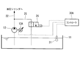
- FIG. 1 shows a pitch control device 10 of a blade 5 as a schematic configuration example around an oil supply pump.
- the pitch control device 10 can individually hydraulically control the blade pitch angle of the three blades 5 attached to the rotor head 4.
- the servo valve 14 switches the hydraulic flow path according to the direction in which the pitch angle of the blade 5 is changed.
- the hydraulic fluid supplied to the blade pitch cylinder 15 presses the piston 15a to the left or right according to the hydraulic flow path set by the servo valve 14.
- the blade 5 connected to the piston rod 15b rotates according to the moving direction of the piston 15a and the piston rod 15b, and is adjusted to a desired blade pitch angle.
- the piston 15a that receives the supply of hydraulic fluid moves in the blade pitch cylinder 15 and presses the opposite hydraulic fluid. For this reason, the hydraulic fluid pressed by the piston 15 a is returned to the oil tank 11 through the servo valve 15 and the return flow path 23.
- the oil temperature of the hydraulic fluid supplied to the hydraulic pipe 22 gradually increases to a predetermined value due to friction between the hydraulic fluid and the pipe wall surface, self-friction of the hydraulic fluid, and the like. Accordingly, the hydraulic pipe 22 to which the hydraulic fluid is supplied and the devices provided in the hydraulic pipe 22 are alleviated from a rapid increase in temperature from a low temperature state cooled by the outside air temperature. At this time, since the bypass flow path 25 is effective, the hydraulic fluid can return to the oil tank 11 through the bypass flow path 25, and therefore, the internal pressure of the hydraulic pipe 22 can be prevented from rapidly increasing.
Landscapes
- Engineering & Computer Science (AREA)
- Life Sciences & Earth Sciences (AREA)
- Sustainable Development (AREA)
- Sustainable Energy (AREA)
- Chemical & Material Sciences (AREA)
- Combustion & Propulsion (AREA)
- Mechanical Engineering (AREA)
- General Engineering & Computer Science (AREA)
- Wind Motors (AREA)
Abstract
Description
このような風力発電装置においては、風況に応じて所定の回転速度と出力とを得るように、油圧を用いて各ブレードのブレードピッチ角度を個別に調整するピッチ制御が行われている。さらに、風力発電装置を構成する増速機や軸受等の回転・摺動部については、潤滑油をポンプで循環させて対象箇所の潤滑を行っている。
このため、従来の風力発電装置においては、油貯蔵タンク内にヒータを設置して加温することが行われている。しかし、ヒータによる加温はヒータ周りの油温しか温度上昇させることができず、従って、効率が悪いという問題を有している。また、油圧ポンプ等の電動機駆動用電源とは別に、ヒータ用として容量の大きな電源を新たに設けることも必要になる。
本発明は、上記の事情に鑑みてなされたものであり、その目的とするところは、容量の大きい新たな電源が不要な油温低下対策を備えている風力発電装置を提供することにある。
本発明に係る風力発電装置の第1の態様は、風車停止時に運転停止される油類供給ポンプを備えている風力発電装置であって、前記油類供給ポンプの吐出側流路から分岐して油類貯蔵タンクに接続されるバイパス流路と、該バイパス流路に設けられて前記油類供給ポンプのポンプ起動時に開となる開閉弁と、前記油類の油温を検出する温度検出部と、前記油類供給ポンプのポンプ起動後にポンプインチングを行って前記油類の温度を所定値まで上昇させる制御部とを備えている。
3 ナセル
4 ローターヘッド
5 ブレード(風車回転翼)
10 ピッチ制御装置
11,11A 油タンク(油類貯蔵タンク)
12,12A 油圧ポンプ(油類供給ポンプ)
12B 潤滑油ポンプ(油類供給ポンプ)
13,13A 電動機
22 油圧配管
22A 潤滑油供給配管
25 バイパス流路
26 電磁弁(開閉弁)
30,30A,30B,30C コントローラ
31 温度センサ(温度検出部)
40 増速機
図2に示す風力発電装置1は、基礎6上に立設される支柱2と、支柱2の上端に設置されるナセル3と、略水平な軸線周りに回転可能にしてナセル3に設けられるローターヘッド4とを有している。
なお、図示の風力発電装置1は、ナセル3の前方でブレード5が回転するアップウインド型と呼ばれるタイプである。
図1は、油類供給ポンプ周りの概略構成例として、ブレード5のピッチ制御装置10を示している。このピッチ制御装置10は、ローターヘッド4に取り付けられた3枚のブレード5について、ブレードピッチ角度を個別に油圧制御することができる。
電動機13には固定容量型や可変容量型があり、本実施形態では、固定容量型の電動機13を用い、吐出量が回転数に応じて変化するギアポンプ等の油圧ポンプ12を駆動する。
なお、風力発電装置1の運転を停止した場合には、上述したピッチ制御装置10も停止状態となるため、電動機13及び油圧ポンプ12が運転されることはない。
油圧ポンプ12が運転されると、油タンク11内の油圧作動油が吸引・昇圧され、油圧配管22を通ってサーボ弁14に供給される。
油圧作動油の供給を受けるピストン15aは、翼ピッチシリンダ15内を移動して反対側の油圧作動油を押圧する。このため、ピストン15aに押圧された油圧作動油は、サーボ弁15及び戻り流路23を通って油タンク11に戻される。
緊急停止バルブ17は常時閉の電磁弁であり、サーボ弁14の故障時等に開いて翼ピッチシリンダ15の予め定めた一方に対して油圧作動油を供給する。この結果、ブレード5が所定の緊急停止位置まで回動し、ピッチ制御装置10の故障に対応することができる。
そこで、風力発電装置1の運転を開始または再開するにあたり、油ポンプ12の運転開始時に油圧作動油の油温が所定値より低い場合には、油圧ポンプ12の起動・停止を短時間に繰り返すポンプインチングを実施し、油圧作動油を徐々に油圧配管22の配管系統へ供給する。この場合、油圧作動油の油温は、たとえば温度センサ31が検出した油タンク11内の油温を採用すればよい。
この後、固定容量型の電動機13にパルス波を入力し、油圧ポンプ12がパルス波に対応したON/OFF運転を行うポンプインチングを実施することにより、油圧ポンプ12の運転・停止が短時間で繰り返される。このようなポンプインチングは、油温の上昇により温度センサ31が所定温度を検出するまで継続される。
このとき、バイパス流路25が有効であるから、油圧作動油はバイパス流路25を通って油タンク11に戻ることができ、従って、油圧配管22の内圧が急激に上昇することを防止できる。
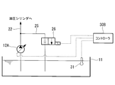
図2は、ピッチ制御装置10の油類供給ポンプ周りについて、概略構成例の要部を示している。なお、上述した実施形態と同様の部分には同じ符号を付し、その詳細な説明は省略する。
この実施形態では、上述したポンプインチングに代えて、油類供給ポンプとして可変容量形の油圧ポンプ12Aを採用し、油温に応じた油圧作動油の流量を油圧配管22に供給する点が異なっている。
図示の構成例では、増速機50の回転・摺動部である軸受41及び歯車42の噛合部に対し、潤滑油ポンプ12Bを運転して油タンク11A内の潤滑油を供給する。潤滑油ポンプ12Bには、たとえば固定容量形の電動機13により駆動されるギアポンプ等が用いられる。
潤滑油ポンプ12Bから吐出された潤滑油は、潤滑油供給配管22Aを通って軸受41及び歯車42に供給され、必要箇所を潤滑した後に潤滑油戻し流路23Aを通って油タンク11に戻される。
この後、固定容量型の電動機13にパルス波を入力し、潤滑油ポンプ12Bがパルス波に対応したON/OFF運転を行うポンプインチングを実施することにより、潤滑油ポンプ12Bの運転・停止が短時間で繰り返される。このようなポンプインチングは、油温の上昇により温度センサ31が所定温度を検出するまで継続され、従って、油圧配管22の内圧が急激に上昇することを防止できる。
なお、本発明は上述した実施形態に限定されることはなく、その要旨を逸脱しない範囲内において適宜変更することができる。
Claims (4)
- 風車停止時に運転停止される油類供給ポンプを備えている風力発電装置であって、
前記油類供給ポンプの吐出側流路から分岐して油類貯蔵タンクに接続されるバイパス流路と、該バイパス流路に設けられて前記油類供給ポンプのポンプ起動時に開となる開閉弁と、前記油類の油温を検出する温度検出部と、前記油類供給ポンプのポンプ起動後にポンプインチングを行って前記油類の温度を所定値まで上昇させる制御部とを備えている風力発電装置。 - 前記ポンプインチングが、前記油類供給ポンプを駆動する固定容量型モータにパルス波を入力して行われる請求項1に記載の風力発電装置。
- 前記ポンプインチングが、前記油類供給ポンプを駆動する可変容量型モータの電流値を制御して行われる請求項1に記載の風力発電装置。
- 風車停止時に運転停止される油類供給ポンプを備えている風力発電装置であって、
前記油類供給ポンプを可変吐出量型ポンプとし、前記油類供給ポンプの吐出側流路から分岐して油類貯蔵タンクに接続されるバイパス流路と、該バイパス流路に設けられて前記油類供給ポンプのポンプ起動時に開となる開閉弁と、前記油類の油温を検出する温度検出部と、前記油類供給ポンプの運転開始時に前記油類供給ポンプの流量制御を行って前記油類の温度を所定値まで上昇させる制御部とを備えている風力発電装置。
Priority Applications (9)
| Application Number | Priority Date | Filing Date | Title |
|---|---|---|---|
| PCT/JP2008/062183 WO2010001479A1 (ja) | 2008-07-04 | 2008-07-04 | 風力発電装置 |
| CA2718489A CA2718489A1 (en) | 2008-07-04 | 2008-07-04 | Wind turbine hydraulic circuit |
| EP08777898.1A EP2295796A4 (en) | 2008-07-04 | 2008-07-04 | DEVICE FOR GENERATING WIND ENERGY |
| CN2008801283640A CN101981313B (zh) | 2008-07-04 | 2008-07-04 | 风力发电装置 |
| US12/933,449 US20110012353A1 (en) | 2008-07-04 | 2008-07-04 | Wind power generator |
| AU2008358707A AU2008358707A1 (en) | 2008-07-04 | 2008-07-04 | Wind power generator |
| BRPI0822488-9A BRPI0822488A2 (pt) | 2008-07-04 | 2008-07-04 | Gerador de energia eólica |
| KR1020107021436A KR20100126766A (ko) | 2008-07-04 | 2008-07-04 | 풍력 발전 장치 |
| JP2010518863A JP5260651B2 (ja) | 2008-07-04 | 2008-07-04 | 風力発電装置 |
Applications Claiming Priority (1)
| Application Number | Priority Date | Filing Date | Title |
|---|---|---|---|
| PCT/JP2008/062183 WO2010001479A1 (ja) | 2008-07-04 | 2008-07-04 | 風力発電装置 |
Publications (1)
| Publication Number | Publication Date |
|---|---|
| WO2010001479A1 true WO2010001479A1 (ja) | 2010-01-07 |
Family
ID=41465595
Family Applications (1)
| Application Number | Title | Priority Date | Filing Date |
|---|---|---|---|
| PCT/JP2008/062183 Ceased WO2010001479A1 (ja) | 2008-07-04 | 2008-07-04 | 風力発電装置 |
Country Status (9)
| Country | Link |
|---|---|
| US (1) | US20110012353A1 (ja) |
| EP (1) | EP2295796A4 (ja) |
| JP (1) | JP5260651B2 (ja) |
| KR (1) | KR20100126766A (ja) |
| CN (1) | CN101981313B (ja) |
| AU (1) | AU2008358707A1 (ja) |
| BR (1) | BRPI0822488A2 (ja) |
| CA (1) | CA2718489A1 (ja) |
| WO (1) | WO2010001479A1 (ja) |
Cited By (5)
| Publication number | Priority date | Publication date | Assignee | Title |
|---|---|---|---|---|
| WO2011096076A1 (ja) * | 2010-02-08 | 2011-08-11 | 三菱重工業株式会社 | 潤滑油加熱機構、歯車機構、及び風力発電装置 |
| WO2011101982A1 (ja) * | 2010-02-19 | 2011-08-25 | 三菱重工業株式会社 | 回転機械の起動方法、及び、風力発電装置の起動方法 |
| JP2015521267A (ja) * | 2012-06-05 | 2015-07-27 | ツェットエフ ウィンド パワー アントワープ エヌ ヴイZf Wind Power Antwerpen N.V. | 風力タービン用ギアボックスの潤滑方法 |
| WO2017149605A1 (ja) * | 2016-02-29 | 2017-09-08 | 三菱重工業株式会社 | 風車並びにその制御装置及び制御方法 |
| US20220042592A1 (en) * | 2018-09-27 | 2022-02-10 | Zf Friedrichshafen Ag | Measuring arrangement for lubricant |
Families Citing this family (9)
| Publication number | Priority date | Publication date | Assignee | Title |
|---|---|---|---|---|
| DK201070305A (en) * | 2010-06-30 | 2011-07-01 | Vestas Wind Sys As | A pitch system |
| FR2970504B1 (fr) * | 2011-01-19 | 2013-02-08 | Turbomeca | Procede et dispositif d'alimentation en lubrifiant |
| FI20115793A0 (fi) * | 2011-08-12 | 2011-08-12 | Mervento Oy | Tuuliturbiinin lapakulman säätöjärjestelmä |
| DK2573391T3 (en) | 2011-09-22 | 2019-01-21 | Moventas Gears Oy | Method and arrangement for controlling the lubrication of an exchange |
| US8869940B2 (en) | 2012-01-17 | 2014-10-28 | General Electric Company | Dual temperature oil control system and method for a wind turbine gearbox |
| DK2992207T3 (en) * | 2013-04-29 | 2018-08-20 | Vestas Wind Sys As | PROCEDURE TO START A WINDMILL IN A COLD CLIMATE ENVIRONMENT |
| CN105484949B (zh) * | 2016-02-01 | 2018-07-27 | 北京金风科创风电设备有限公司 | 风力发电机的轴承保护方法及装置 |
| EP4102084A1 (en) * | 2021-06-11 | 2022-12-14 | Siemens Gamesa Renewable Energy A/S | Method of operating a hydraulic system from an off-state in a cold environment |
| FR3131274A1 (fr) * | 2021-12-23 | 2023-06-30 | Safran Aircraft Engines | Circuit de commande hydraulique de calage d’aubes de soufflante |
Citations (7)
| Publication number | Priority date | Publication date | Assignee | Title |
|---|---|---|---|---|
| JPH0742662A (ja) * | 1993-07-28 | 1995-02-10 | Mitsubishi Heavy Ind Ltd | 風 車 |
| JPH08193591A (ja) * | 1994-01-20 | 1996-07-30 | Meiki Co Ltd | 油圧ポンプのインチング装置 |
| JPH11117914A (ja) * | 1997-10-17 | 1999-04-27 | Komatsu Ltd | 建設機械の油圧駆動装置 |
| JP2002327714A (ja) * | 2001-04-27 | 2002-11-15 | Kobelco Contstruction Machinery Ltd | 建設機械の油圧回路 |
| JP2005023867A (ja) * | 2003-07-04 | 2005-01-27 | Ts Corporation | 風車羽根のピッチ角駆動装置 |
| JP2005155698A (ja) * | 2003-11-21 | 2005-06-16 | Sumitomo (Shi) Construction Machinery Manufacturing Co Ltd | 油圧作業機械の油圧回路 |
| JP2008051263A (ja) * | 2006-08-25 | 2008-03-06 | Daikin Ind Ltd | 油圧システム |
Family Cites Families (4)
| Publication number | Priority date | Publication date | Assignee | Title |
|---|---|---|---|---|
| DE10157714A1 (de) * | 2001-11-24 | 2003-06-26 | Daimler Chrysler Ag | Verfahren und Vorrichtungen zur Durchführung des Verfahrens zum Beeinflussen der Betriebstemperatur eines hydraulischen Betriebsmittels für ein Antriebsaggregat eines Fahrzeuges |
| ATE471462T1 (de) * | 2002-04-24 | 2010-07-15 | Vestas Wind Sys As | Windturbine, hydrauliksystem, entlüftungssystem und verfahren zur steuerung mindestens zweier windturbinenschaufeln |
| WO2004076855A1 (en) * | 2003-02-27 | 2004-09-10 | Avn Hydraulik A/S | Pitch regulation system |
| CN2675879Y (zh) * | 2003-11-11 | 2005-02-02 | 江苏省机电研究所有限公司 | 混凝土泵风扇驱动系统 |
-
2008
- 2008-07-04 BR BRPI0822488-9A patent/BRPI0822488A2/pt not_active IP Right Cessation
- 2008-07-04 CA CA2718489A patent/CA2718489A1/en not_active Abandoned
- 2008-07-04 US US12/933,449 patent/US20110012353A1/en not_active Abandoned
- 2008-07-04 KR KR1020107021436A patent/KR20100126766A/ko not_active Abandoned
- 2008-07-04 AU AU2008358707A patent/AU2008358707A1/en not_active Abandoned
- 2008-07-04 WO PCT/JP2008/062183 patent/WO2010001479A1/ja not_active Ceased
- 2008-07-04 JP JP2010518863A patent/JP5260651B2/ja not_active Expired - Fee Related
- 2008-07-04 EP EP08777898.1A patent/EP2295796A4/en not_active Withdrawn
- 2008-07-04 CN CN2008801283640A patent/CN101981313B/zh not_active Expired - Fee Related
Patent Citations (7)
| Publication number | Priority date | Publication date | Assignee | Title |
|---|---|---|---|---|
| JPH0742662A (ja) * | 1993-07-28 | 1995-02-10 | Mitsubishi Heavy Ind Ltd | 風 車 |
| JPH08193591A (ja) * | 1994-01-20 | 1996-07-30 | Meiki Co Ltd | 油圧ポンプのインチング装置 |
| JPH11117914A (ja) * | 1997-10-17 | 1999-04-27 | Komatsu Ltd | 建設機械の油圧駆動装置 |
| JP2002327714A (ja) * | 2001-04-27 | 2002-11-15 | Kobelco Contstruction Machinery Ltd | 建設機械の油圧回路 |
| JP2005023867A (ja) * | 2003-07-04 | 2005-01-27 | Ts Corporation | 風車羽根のピッチ角駆動装置 |
| JP2005155698A (ja) * | 2003-11-21 | 2005-06-16 | Sumitomo (Shi) Construction Machinery Manufacturing Co Ltd | 油圧作業機械の油圧回路 |
| JP2008051263A (ja) * | 2006-08-25 | 2008-03-06 | Daikin Ind Ltd | 油圧システム |
Non-Patent Citations (1)
| Title |
|---|
| See also references of EP2295796A4 * |
Cited By (12)
| Publication number | Priority date | Publication date | Assignee | Title |
|---|---|---|---|---|
| WO2011096076A1 (ja) * | 2010-02-08 | 2011-08-11 | 三菱重工業株式会社 | 潤滑油加熱機構、歯車機構、及び風力発電装置 |
| JP5186004B2 (ja) * | 2010-02-08 | 2013-04-17 | 三菱重工業株式会社 | 潤滑油加熱機構、歯車機構、及び風力発電装置 |
| WO2011101982A1 (ja) * | 2010-02-19 | 2011-08-25 | 三菱重工業株式会社 | 回転機械の起動方法、及び、風力発電装置の起動方法 |
| AU2010204474B2 (en) * | 2010-02-19 | 2012-05-24 | Mitsubishi Heavy Industries, Ltd. | Starting method for rotating machine and starting method for wind turbine generator |
| AU2010204474B9 (en) * | 2010-02-19 | 2012-09-20 | Mitsubishi Heavy Industries, Ltd. | Starting method for rotating machine and starting method for wind turbine generator |
| JP5285707B2 (ja) * | 2010-02-19 | 2013-09-11 | 三菱重工業株式会社 | 回転機械の起動方法、及び、風力発電装置の起動方法 |
| US8887868B2 (en) | 2010-02-19 | 2014-11-18 | Mitsubishi Heavy Industries, Ltd. | Starting method for rotating machine and starting method for wind turbine generator |
| JP2015521267A (ja) * | 2012-06-05 | 2015-07-27 | ツェットエフ ウィンド パワー アントワープ エヌ ヴイZf Wind Power Antwerpen N.V. | 風力タービン用ギアボックスの潤滑方法 |
| WO2017149605A1 (ja) * | 2016-02-29 | 2017-09-08 | 三菱重工業株式会社 | 風車並びにその制御装置及び制御方法 |
| JPWO2017149605A1 (ja) * | 2016-02-29 | 2018-04-12 | 三菱重工業株式会社 | 風車並びにその制御装置及び制御方法 |
| US20220042592A1 (en) * | 2018-09-27 | 2022-02-10 | Zf Friedrichshafen Ag | Measuring arrangement for lubricant |
| US11566700B2 (en) * | 2018-09-27 | 2023-01-31 | Zf Friedrichshafen Ag | Measuring arrangement for lubricant |
Also Published As
| Publication number | Publication date |
|---|---|
| JP5260651B2 (ja) | 2013-08-14 |
| BRPI0822488A2 (pt) | 2015-06-16 |
| JPWO2010001479A1 (ja) | 2011-12-15 |
| CA2718489A1 (en) | 2010-01-07 |
| US20110012353A1 (en) | 2011-01-20 |
| EP2295796A4 (en) | 2013-06-19 |
| EP2295796A1 (en) | 2011-03-16 |
| CN101981313B (zh) | 2013-07-10 |
| CN101981313A (zh) | 2011-02-23 |
| AU2008358707A1 (en) | 2010-01-07 |
| KR20100126766A (ko) | 2010-12-02 |
Similar Documents
| Publication | Publication Date | Title |
|---|---|---|
| JP5260651B2 (ja) | 風力発電装置 | |
| CN102725522B (zh) | 旋转机械的起动方法及风力发电装置的起动方法 | |
| EP2405145A2 (en) | Method for Monitoring a Component in a Hydraulic Circuit, Monitoring Device and Fluid Turbine | |
| JP6401419B2 (ja) | 風車並びにその制御装置及び制御方法 | |
| JP5364842B1 (ja) | 再生エネルギー型発電装置およびその制御方法 | |
| EP2217806B1 (en) | Electro-hydraulic actuator for controlling the pitch of a blade of a wind turbine | |
| JP6386375B2 (ja) | 風力発電設備および増速機 | |
| US8511079B2 (en) | Piecewise variable displacement power transmission | |
| EA006363B1 (ru) | Ветротурбина с гидравлической трансмиссией | |
| JP5331197B2 (ja) | 翼ピッチ制御装置、風力発電装置、及び翼ピッチ制御方法 | |
| CN113294291B (zh) | 通过使用液压系统来控制风力涡轮机的叶片桨距角的方法 | |
| KR101265435B1 (ko) | 회전 기계의 기동 방법 및 풍력 발전 장치의 기동 방법 | |
| JP2002364516A (ja) | 風車の可変翼装置 | |
| CA3144730A1 (en) | Pump jack system | |
| JP2020020432A (ja) | 油脂供給装置およびそれを用いた風力発電システム |
Legal Events
| Date | Code | Title | Description |
|---|---|---|---|
| WWE | Wipo information: entry into national phase |
Ref document number: 200880128364.0 Country of ref document: CN |
|
| 121 | Ep: the epo has been informed by wipo that ep was designated in this application |
Ref document number: 08777898 Country of ref document: EP Kind code of ref document: A1 |
|
| WWE | Wipo information: entry into national phase |
Ref document number: 2008358707 Country of ref document: AU |
|
| WWE | Wipo information: entry into national phase |
Ref document number: 2010518863 Country of ref document: JP Ref document number: 2718489 Country of ref document: CA |
|
| WWE | Wipo information: entry into national phase |
Ref document number: 12933449 Country of ref document: US |
|
| WWE | Wipo information: entry into national phase |
Ref document number: 6659/DELNP/2010 Country of ref document: IN |
|
| ENP | Entry into the national phase |
Ref document number: 20107021436 Country of ref document: KR Kind code of ref document: A |
|
| WWE | Wipo information: entry into national phase |
Ref document number: 2008777898 Country of ref document: EP |
|
| ENP | Entry into the national phase |
Ref document number: 2008358707 Country of ref document: AU Date of ref document: 20080704 Kind code of ref document: A |
|
| NENP | Non-entry into the national phase |
Ref country code: DE |
|
| ENP | Entry into the national phase |
Ref document number: PI0822488 Country of ref document: BR Kind code of ref document: A2 Effective date: 20100922 |