WO2010001706A1 - 軸受用ころ、軸受、および軸受用ころ加工方法 - Google Patents
軸受用ころ、軸受、および軸受用ころ加工方法 Download PDFInfo
- Publication number
- WO2010001706A1 WO2010001706A1 PCT/JP2009/060737 JP2009060737W WO2010001706A1 WO 2010001706 A1 WO2010001706 A1 WO 2010001706A1 JP 2009060737 W JP2009060737 W JP 2009060737W WO 2010001706 A1 WO2010001706 A1 WO 2010001706A1
- Authority
- WO
- WIPO (PCT)
- Prior art keywords
- roller
- outer diameter
- bearing
- end surface
- diameter surface
- Prior art date
- Legal status (The legal status is an assumption and is not a legal conclusion. Google has not performed a legal analysis and makes no representation as to the accuracy of the status listed.)
- Ceased
Links
Images






Classifications
-
- F—MECHANICAL ENGINEERING; LIGHTING; HEATING; WEAPONS; BLASTING
- F16—ENGINEERING ELEMENTS AND UNITS; GENERAL MEASURES FOR PRODUCING AND MAINTAINING EFFECTIVE FUNCTIONING OF MACHINES OR INSTALLATIONS; THERMAL INSULATION IN GENERAL
- F16C—SHAFTS; FLEXIBLE SHAFTS; ELEMENTS OR CRANKSHAFT MECHANISMS; ROTARY BODIES OTHER THAN GEARING ELEMENTS; BEARINGS
- F16C33/00—Parts of bearings; Special methods for making bearings or parts thereof
- F16C33/30—Parts of ball or roller bearings
- F16C33/34—Rollers; Needles
- F16C33/36—Rollers; Needles with bearing-surfaces other than cylindrical, e.g. tapered; with grooves in the bearing surfaces
-
- F—MECHANICAL ENGINEERING; LIGHTING; HEATING; WEAPONS; BLASTING
- F16—ENGINEERING ELEMENTS AND UNITS; GENERAL MEASURES FOR PRODUCING AND MAINTAINING EFFECTIVE FUNCTIONING OF MACHINES OR INSTALLATIONS; THERMAL INSULATION IN GENERAL
- F16C—SHAFTS; FLEXIBLE SHAFTS; ELEMENTS OR CRANKSHAFT MECHANISMS; ROTARY BODIES OTHER THAN GEARING ELEMENTS; BEARINGS
- F16C33/00—Parts of bearings; Special methods for making bearings or parts thereof
- F16C33/30—Parts of ball or roller bearings
- F16C33/58—Raceways; Race rings
- F16C33/64—Special methods of manufacture
-
- F—MECHANICAL ENGINEERING; LIGHTING; HEATING; WEAPONS; BLASTING
- F16—ENGINEERING ELEMENTS AND UNITS; GENERAL MEASURES FOR PRODUCING AND MAINTAINING EFFECTIVE FUNCTIONING OF MACHINES OR INSTALLATIONS; THERMAL INSULATION IN GENERAL
- F16C—SHAFTS; FLEXIBLE SHAFTS; ELEMENTS OR CRANKSHAFT MECHANISMS; ROTARY BODIES OTHER THAN GEARING ELEMENTS; BEARINGS
- F16C2240/00—Specified values or numerical ranges of parameters; Relations between them
- F16C2240/40—Linear dimensions, e.g. length, radius, thickness, gap
- F16C2240/50—Crowning, e.g. crowning height or crowning radius
Definitions
- the present invention relates to a bearing roller, a bearing, and a bearing roller processing method.
- Bearings include cylindrical roller bearings using cylindrical rollers, tapered roller bearings using tapered rollers, and centering roller bearings using centering rollers.
- the inner ring portion is in line contact and the outer ring portion is in line contact.
- Cylindrical roller bearings have a large radial load capacity and are suitable for heavy loads.
- the tapered roller bearing has a conical shape in which the race of the inner ring, the race of the outer ring, and the rollers each have a head cut.
- the inner ring raceway, the outer ring raceway, and the conical vertices of the rollers are designed to be gathered at one point on the axis.
- the race of the outer ring is designed to be a spherical surface centered on a point that coincides with the center of the bearing, and the roller is attached to the inner ring together with the cage in a barrel shape.
- FIG. 11 shows a self-aligning roller bearing, which is an inner ring 1 having two rows of raceway surfaces 1a and 1b on the outer diameter surface, and a raceway facing the raceway surfaces 1a and 1b of the inner ring 1 on the inner diameter surface.
- the outer ring 2 provided with the surface 2a, the two rows of rollers 3 arranged between the raceways 1a, 1b and 2a of the inner ring 1 and the outer ring 2, and an integrated cage 4 for holding these two rows of rollers 3.
- the inner ring 1 is provided with a middle collar part 5 between the raceway surfaces 1a and 1b, and is provided with outer collar parts 6 and 6 at axial end parts. For this reason, the roller 3 is interposed between the middle collar part 5 and the outer collar part 6.
- the outer diameter surface 3a is a spherical surface having a curvature corresponding to the raceway surface of the outer ring 2
- the large end surface 3b is a spherical surface having a larger curvature than the outer diameter surface 3a
- the small end surface 3c is straight. It is considered as a surface.
- rounded portions Ra and Ra are formed at the boundary between the outer diameter surface 3a and the large end surface 3b and at the boundary between the outer diameter surface 3a and the small end surface 3c, respectively. In many cases, such rounded portions Ra and Ra are generally used while leaving a corner rounded at the time of material processing. Further, the processing of the outer diameter surface 3a, the processing of the end surfaces 3b and 3c, and the processing of the rounded portions Ra and Ra were performed at different rotation centers.
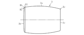
- rollers 3 there are rollers 3 as shown in FIG.
- the roller 3 is provided with chamfered rounded portions Rb and Rc at the boundary between the outer diameter surface 3a and the large end surface 3b and the boundary between the outer diameter surface 3a and the small end surface 3c, respectively.
- the chamfered rounded portion Rb continues smoothly through the first rounded portion R1, and the large end surface 3b and the chamfered rounded portion Rb continue smoothly through the second rounded portion R2.
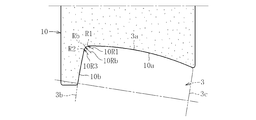
- the roller 3 shown in FIG. 12 uses a grinding wheel 10 as shown in FIG. 13 as described in Patent Document 1.
- the grinding wheel 10 includes an outer diameter grinding portion 10a for grinding the outer diameter surface 3a of the roller 3, a large end surface grinding portion 10b for grinding the large end surface 3b, and a chamfering grinding portion 10Rb for grinding the chamfered radius portion Rb.
- the 1st rounding part 10R1 and the 2nd rounding part 10R2 are provided.
- the first round grinding portion 10R1 has a radius of curvature corresponding to the first round R1 of the roller 3, and smoothly connects the outer diameter grinding portion 10a and the chamfering grinding portion 10Rb.
- the second rounded grinding part 10R2 has a radius of curvature corresponding to the second rounded R2 of the roller 3, and smoothly connects the large end face grinding part 10b and the chamfered grinding part 10Rb.
- the outer diameter surface 3a, the large end surface 3b, and the chamfered rounded portion Rb of the roller 3 are ground simultaneously.
- each processing surface can be processed with high accuracy.
- the relationship between the processed surfaces becomes unstable. That is, the corner of the finished product may not be concentric with the center of rotation of the roller. For this reason, there is a possibility that a highly accurate product (roller) cannot be provided.
- the grinding wheel 10 as shown in FIG. 13 is affected by the size of the material, and if the outer diameter is made uniform, the overall length may vary, and if the entire length is made uniform, the outer diameter may vary.
- the present invention provides a bearing roller that can be molded with high accuracy and can achieve a long life, a method for processing the bearing roller, can reduce rotational torque, and can improve rotational accuracy. It is in providing a bearing that can be achieved.
- the bearing roller of the present invention is a bearing roller in which center holes are formed on both end surfaces, respectively, and the outer diameter surface and the rounded portion of the end surface and the outer diameter surface are supported in the center hole. It is processed so as to be smoothly continuous.
- Edge load may occur in the bearing.
- the edge load means that, when the shape of the roller is inadequate in contact with the raceway ring, a local increase in surface pressure occurs at the end, and early peeling occurs from that point. For this reason, if the outer diameter surface and the corner portion between the end surface and the outer diameter surface are not continuously continuous, an edge load may occur.
- the bearing roller of the present invention since the outer diameter surface and the rounded portion of the corner between the end surface and the outer diameter surface are processed smoothly, when this roller is incorporated in the bearing, Edge load can be suppressed and rotational torque can be reduced.
- It may be a cylindrical roller, a tapered roller, or a centering roller.
- the bearing of the present invention uses the bearing roller described above.
- the processing method of the bearing roller according to the present invention grinds the end surface and the end surface side rounded portion in the rounded portion while rotating around its axis by gripping the outer diameter surface while being supported by the center holes on both end surfaces.
- the outer diameter surface and the outer diameter of the rounded portion are rotated around its axis by driving force transmission from at least one of the end surfaces while being supported by the center holes on both end surfaces and the end surface grinding process.
- an outer diameter surface grinding step for grinding the surface-side corner portion for grinding the surface-side corner portion.
- the end face and the end face side rounded part in the rounded part can be ground while being supported by the center hole, and the outer side is supported in the center hole.
- the outer diameter surface side corner portion in the radial surface and the rounded portion can be ground. For this reason, high quality processing becomes possible.
- the bearing incorporating the bearing roller of the present invention can suppress the edge load, the load applied to the inner ring and the outer ring is reduced, and the life of the bearing can be extended. Further, the rotational torque can be reduced, and high-precision rotation can be obtained.
- the separately processed parts are also concentric, and the outer diameter surface and the corner portion between the end surface and the outer diameter surface are smoothly continuous. Processing is possible. Furthermore, since the end surface and the outer diameter surface can be processed separately, the dimensional accuracy is improved, and the rotational accuracy of the bearing using the roller thus processed is improved.
- FIG. 2 is an enlarged view of a corner portion between a large end surface and an outer diameter surface of the roller shown in FIG. 1.
- FIG. 2 is an enlarged view of a corner portion between a small end surface and an outer diameter surface of the roller shown in FIG. 1.
- It is a simplified block diagram of the roller processing method for bearings which shows the embodiment of the present invention. It is a simplified diagram showing a hardened steel cutting process. It is a schematic diagram which shows an end surface grinding process. It is a principal part enlarged view of the grindstone shown in FIG. It is a simplified diagram showing an outer diameter surface grinding process. It is a principal part enlarged view of the grindstone shown in FIG. It is a graph which shows a residual stress. It is principal part sectional drawing which shows the conventional bearing. It is an enlarged view of the said conventional roller for bearings. It is principal part sectional drawing of the conventional grinding wheel used for the roller processing for bearings.
- this bearing roller 20 is a self-aligning roller.
- Self-aligning roller bearings include asymmetric roller bearings and symmetrical roller bearings depending on the shape of the rollers.
- the asymmetric roller bearing uses an asymmetric roller whose maximum diameter is out of the center of the length. In the symmetric roller bearing, a symmetric roller having a maximum diameter at the center of the length is used.
- the roller 20 of this embodiment is an asymmetric roller, and the maximum outer diameter portion M of the outer diameter surface 20a is deviated from the axial center line.
- the large end surface 20b is a spherical surface having a larger curvature than the outer diameter surface 20a, and the small end surface 20c is a straight surface. That is, B> A> C, where A is the outer diameter of the large end surface 20b, B is the outer diameter of the largest outer diameter portion M, and C is the outer diameter of the small end surface 20c.
- a rounded portion 21 is formed at a corner between the outer diameter surface 20a and the large end surface 20b.
- a rounded portion 22 is formed at a corner between the outer diameter surface 20a and the small end surface 20c.
- the rounded portion 21 includes an outer diameter surface side corner portion 21a on the outer diameter surface 20a side, a large end surface side corner portion 21b on the large end surface 20b side, an outer diameter surface side corner portion 21a and a large end surface. It consists of the intermediate
- the radius of curvature of the outer diameter surface side corner portion 21a is Ra
- the large end surface side corner portion 21b is Rb
- the intermediate round portion 21c Rc
- Ra Rb.
- the rounded portion 22 includes an outer diameter surface side corner portion 22a on the outer diameter surface 20a side and a small end surface side corner portion 22b on the small end surface 20c side.
- ra the curvature radius of the outer diameter surface side corner portion 22a
- rb the large end surface side corner portion 22b
- the outer diameter surface 20a and the rounded portion 21 of the large end surface 20b and the outer diameter surface 20a are processed so as to be smoothly continuous, and the outer diameter surface 20a and the rounded portion 22 of the small end surface 20c and the outer diameter surface 20a are smooth. It is processed to be continuous. Further, as shown in FIG. 1, center holes 23 and 24 disposed on the roller axis are provided in the large end surface 20b and the small end surface 20c.
- the roller in this case is a tapered roller, and a corner portion 21 including an outer diameter surface side corner portion 21a, an intermediate radius portion 21c, and a large end surface side corner portion 21b is formed on the large end surface 20b side.
- a corner portion 22 composed of an outer diameter surface side corner portion 22a and a small end surface side corner portion 22b is formed.
- the hardened steel cutting process 70 which rough-processes the surface
- the end surface grinding process 71 which grinds the end surface side rounded portions 21b and 22b in the end surfaces 20b and 20c and the rounded portions 21 and 22, as shown in FIG.
- an outer diameter surface grinding step 72 for grinding the outer diameter surface side corner portions 21a, 22a in the outer diameter surface 20a and the rounded portions 21, 22.
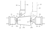
- the hardened steel cutting process 70 uses a chuck device 30 that supports the center holes 23 and 24 of the roller 20 as shown in FIG.
- the chuck device 30 includes a driving side member 31 and a driven side member 32.
- the drive side member 31 includes a rotating body 33, a transmission body 34 that transmits the rotational force of the rotating body 33 to the small end face 20c of the roller 20, and a center 35 in which the tip is fitted into the center hole 24 of the small end face 20c.
- the driven member 32 includes a rotating body 36 that freely rotates around its axis and a center 37 whose tip is fitted into the center hole 23 of the large end surface 20b.
- the roller 20 is supported on the axis O at the center 35 of the driving side member 31 and the center 37 of the driven side member 32.
- this rotational force is transmitted to the small end surface 20c of the roller 20 via the transmitting body 34, and the roller 20 rotates about its axis O. To do.
- the cutting tool 40 includes a cutting tool main body 42 and a cutting tool 43 attached to the cutting tool main body 42.
- the cutting tool 40 can cut the outer diameter surface 20a by moving in the arrow direction A along the outer diameter surface 20a, and cut the end surface 20b by moving in the arrow direction B along the end surface 20b. be able to.
- the outer diameter surface 20a and the end surface 20b are cut by one cutting tool 40.
- the outer diameter surface cutting tool and the end surface cutting tool are provided. It may be.
- the cutting in this case is a hardened steel cutting.
- this roller material has a hardened layer formed by heat treatment on the surface, and steel materials (for example, bearing steel, medium carbon steel, etc.) conventionally used for this type of roller are used.
- hardened steel cutting is simply cutting, and since cutting is usually performed in the state of raw material, it is called hardened steel cutting in order to clarify that the cutting is after heat treatment (after quenching). did. Since cutting is performed after quenching, the heat treatment deformation of the material can be removed in this cutting process. When quenching, tensile residual stress tends to remain, and fatigue strength decreases as it is. For this reason, if the surface is cut, a compressive residual stress can be given to the outermost surface portion, thereby improving the fatigue strength.
- Curing treatment is performed by induction hardening (not often used for heat treatment of rollers), (submerged quenching + tempering), carburizing quenching, or the like depending on the material used.
- Quenching by high-frequency heating is a quenching method that applies the principle of heating a conductive object by placing Joule heat in a coil through which high-frequency current flows, and generating Joule heat by electromagnetic induction. is there.
- Carburizing and quenching is a process in which carbon is impregnated from the surface layer (carburizing treatment) by heating the steel in a carburizing agent such as activated carbon-rich gas, liquid or solid for a long time. It is a method of quenching and tempering steel.
- the small end face 20c can be cut with the cutting tool 41 if the large end face 20b side is supported by the driving side member 31.
- a rounded portion having the same radius of curvature as the curvature radius Rc of the intermediate rounded portion 21c of the rounded portion 21 is formed, and on the small end surface 20c, the rounded portion 22 of the rounded portion 22c is formed.
- a rounded portion having the same curvature radius as the curvature radius rb of the small end face side corner portion 22b is formed.
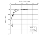
- Fig. 10 shows the relationship between depth from the surface and residual stress.
- No. 1 o and No. 2 ⁇ indicate cutting with a small cutting allowance, and ⁇ indicates heavy cutting with a large cutting allowance. It can be understood that compressive stress is generated on the surface by cutting hardened steel in this way.
- an end face grinding step 71 is performed to grind the end faces 20b and 20c.
- plunge cutting is performed with a grindstone 50 formed by a dress.
- Plunge cut is grinding by sending a grindstone in the radial direction.
- the grindstone 50 includes an end surface grinding part 51 and a corner part grinding part 52.
- the end surface grinding part 51 is disposed on the vertical surface, and the corner part grinding part 52 is inclined with respect to the end surface grinding part 51 so as to form a predetermined angle ⁇ 2 (for example, about 30 degrees).
- the chuck device 55 when using the grindstone 50, a chuck device 55 as shown in FIG. 6 is used.
- the chuck device 55 includes a driving side member 56 and a driven side member 57.
- the driving side member 56 includes a rotating body 58, a transmission body 59 that transmits the rotational force of the rotating body 58 to the outer diameter surface 20a of the roller 20, and a center 60 whose tip is fitted into the center hole 24 of the small end surface 20c.
- the driven member 57 includes a rotating body 61 that freely rotates around its axis and a center 62 whose tip is fitted into the center hole 23 of the large end face 20b. Since the driven side member 57 has the same structure as the driven side member 32 shown in FIG. 5, the driven side member 32 can be used.
- the roller 20 is supported on the axis O by the center 60 of the driving side member 56 and the center 37 of the driven side member 57.
- this rotational force is transmitted to the outer diameter surface 20a of the roller 20 via the transmission body 59, and the roller 20 is rotated around its axis O. Rotate.
- the large end surface 20 b and the large end surface side corner portion 21 c of the rounded portion 21 can be ground by the grindstone 50 while rotating the roller 20 around the axis O by the chuck device 55.
- the small end surface 20c is similar to the grindstone 50, and an end surface grinding portion;
- the small end surface 20c and the small end surface side corner portion 22b of the rounded portion 22 can be ground with a grindstone provided with a corner portion grinding portion.
- an outer diameter surface grinding step 72 is performed to grind the outer diameter surface 20a of the roller as shown in FIG. Also in this case, the plunge cut is performed with the grindstone 65 formed by the dress.
- the grindstone 65 includes a concave portion 66 that is externally fitted to the outer diameter surface 20 a, and the bottom surface of the concave portion 66 serves as the outer diameter surface grinding portion 67.
- the outer diameter surface grinding portion side of the side surface 68 on the large end surface side of the concave portion 66 becomes a corner cutting portion 68a for grinding the outer diameter surface side corner portion 21a.
- the outer diameter surface grinding part side of the side surface 69 on the small end face side of the recess 66 becomes a corner cutting part 69a for grinding the outer diameter surface side corner part 22a.
- the chuck device 30 shown in FIG. 5 can be used as the chuck device.
- the roller 20 when the roller 20 is disposed on the axis at the center 35 of the driving side member 31 and the center 37 of the driven side member 32, and the rotating body 33 on the driving side member 31 side is rotationally driven, The rotational force is transmitted to the small end surface 20c of the roller 20 via the transmission body 34, and the roller 20 rotates about its axis.
- the outer diameter surface 20a and the outer diameter surface side corner portions 21a and 22a of the roller 20 are ground by the grindstone 65 while the roller 20 is rotated about its axis by the chuck device 30. Thereby, the grinding operation (processing operation) for the roller 20 is completed.
- the inclination angle of the outer diameter surface side corner portion 21a is ⁇ 1, for example, it is 30 degrees
- the inclination angle of the outer diameter surface side corner portion 22a is ⁇ 3, for example, 20 degrees. It is said.
- CNC computer numerical control
- the tapered rollers are processed.
- the same processing steps as this processing step are performed. Can be processed.
- the center holes 23 and 24 are formed on both end faces, the outer diameter is supported by the center holes 23 and 24 using such a processing apparatus.
- the corners 21 and 22 of the corners of the surface 20a and the end surfaces 20b and 20c and the outer diameter surface 20a can be processed smoothly.
- the outer diameter surface 20a and the rounded portions 21 and 22 of the end surfaces 20b and 20c and the outer diameter surface 20a are processed so as to be smoothly continuous.
- the edge load can be suppressed and the rotational torque can be reduced.
- the edge load can be suppressed, the load applied to the inner ring and the outer ring is reduced, and the life of the bearing can be extended. Further, the rotational torque can be reduced, and high-precision rotation can be obtained.
- the separately processed parts are also concentric.
- the corner parts 21 and 22 with 20a can be processed smoothly.
- the end surfaces 20b and 20c and the outer diameter surface 20a can be processed separately, the dimensional accuracy is improved, and the rotational accuracy of the bearing using the roller thus processed is improved.
- CNC computer numerical control
- the embodiment of the present invention has been described.
- the present invention is not limited to the above embodiment, and various modifications are possible.
- the curvature radius of each corner part 21 and 22, ie, the curvature radius of the outer surface side corner parts 21a and 22a and the end surface side corner parts 21a and 22b can be set arbitrarily.
- the lapping process is a kind of polishing, and is a process in which abrasive grains are interposed between the workpiece and the tool and rubbed together.
- It may be a cylindrical roller, a tapered roller, or a centering roller. In the case of a self-aligning roller, it can be a symmetric roller bearing.
Landscapes
- Engineering & Computer Science (AREA)
- General Engineering & Computer Science (AREA)
- Mechanical Engineering (AREA)
- Manufacturing & Machinery (AREA)
- Rolling Contact Bearings (AREA)
Abstract
Description
20b 大端面
20c 小端面
21 アール部
22 アール部
23,24 センタ穴
70 焼入鋼切削工程
71 端面研削工程
72 外径面研削工程
Claims (7)
- 両端面にそれぞれセンタ穴が形成された軸受用ころであって、
前記センタ穴に支持された状態で、外径面、及び端面と外径面とのコーナのアール部が滑らかに連続するように加工されてなることを特徴とする軸受用ころ。 - 円筒ころであることを特徴とする請求項1に記載の軸受用ころ。
- 円錐ころであることを特徴とする請求項1に記載の軸受用ころ。
- 調芯ころであることを特徴とする請求項1に記載の軸受用ころ。
- 前記請求項1~請求項4にいずれか1項に記載の軸受用ころを用いたことを特徴とする軸受。
- 両端面のセンタ穴にて支持された状態で、外径面把持によりその軸心廻りに回転させつつ、端面、及びアール部における端面側アール部を研削する端面研削工程と、
両端面のセンタ穴にて支持された状態で、少なくともいずれか一方の端面からの駆動力伝達によってその軸心廻りに回転させつつ、外径面、及びアール部における外径面側コーナ部を研削する外径面研削工程とを備えたことを特徴とする軸受用ころ加工方法。 - 焼入鋼切削にて表面を粗加工した後、前記研削工程を行うことを特徴とする請求項6に記載の軸受用ころ加工方法。
Priority Applications (2)
| Application Number | Priority Date | Filing Date | Title |
|---|---|---|---|
| EP09773284.6A EP2309143B1 (en) | 2008-07-01 | 2009-06-12 | Bearing roller, bearing, and bearing roller processing method |
| CN200980124937.7A CN102076980B (zh) | 2008-07-01 | 2009-06-12 | 自动调心滚子、轴承及自动调心滚子加工方法 |
Applications Claiming Priority (2)
| Application Number | Priority Date | Filing Date | Title |
|---|---|---|---|
| JP2008172604A JP5661235B2 (ja) | 2008-07-01 | 2008-07-01 | 軸受用ころ加工方法 |
| JP2008-172604 | 2008-07-01 |
Publications (1)
| Publication Number | Publication Date |
|---|---|
| WO2010001706A1 true WO2010001706A1 (ja) | 2010-01-07 |
Family
ID=41465809
Family Applications (1)
| Application Number | Title | Priority Date | Filing Date |
|---|---|---|---|
| PCT/JP2009/060737 Ceased WO2010001706A1 (ja) | 2008-07-01 | 2009-06-12 | 軸受用ころ、軸受、および軸受用ころ加工方法 |
Country Status (5)
| Country | Link |
|---|---|
| EP (1) | EP2309143B1 (ja) |
| JP (1) | JP5661235B2 (ja) |
| KR (1) | KR101551316B1 (ja) |
| CN (1) | CN102076980B (ja) |
| WO (1) | WO2010001706A1 (ja) |
Cited By (2)
| Publication number | Priority date | Publication date | Assignee | Title |
|---|---|---|---|---|
| WO2011093215A1 (ja) * | 2010-01-26 | 2011-08-04 | Ntn株式会社 | ころの製造方法 |
| JPWO2023238364A1 (ja) * | 2022-06-10 | 2023-12-14 |
Families Citing this family (11)
| Publication number | Priority date | Publication date | Assignee | Title |
|---|---|---|---|---|
| CN102513894A (zh) * | 2011-12-06 | 2012-06-27 | 瓦房店冶矿轴承制造有限公司 | 一种调心滚子双端面磨削方法 |
| JP2014202329A (ja) * | 2013-04-09 | 2014-10-27 | Ntn株式会社 | 軸受用ころの外面研削方法およびころ軸受 |
| DE102015207106A1 (de) * | 2015-04-20 | 2016-10-20 | Schaeffler Technologies AG & Co. KG | Verfahren zum Herstellen von Wälzkörpern für Wälzlager |
| CN105252223B (zh) * | 2015-11-11 | 2017-10-31 | 宝塔实业股份有限公司 | 特大型轴承带支柱孔圆锥滚动体的加工方法 |
| FR3044571B1 (fr) * | 2015-12-03 | 2018-01-12 | Ntn-Snr Roulements | Procede de profilage d’une arete d’un corps roulant pour un palier a roulement |
| CN108884867B (zh) | 2016-03-24 | 2020-12-18 | Ntn株式会社 | 双排自调心滚子轴承 |
| DE102016220052A1 (de) | 2016-10-14 | 2018-04-19 | Schaeffler Technologies AG & Co. KG | Rolle für ein Wälzlager sowie Wälzlager mit der Rolle |
| ES3000418T3 (en) * | 2017-04-26 | 2025-02-28 | Timken Co | Non-elliptical contact profile for cylindrical roller bearing |
| DE102018213951A1 (de) * | 2018-08-17 | 2020-02-20 | Thyssenkrupp Ag | Wälzkörper mit asymmetrischer Rollenprofilierung, Wälzlager, Windkraftanlage und Verfahren zur geometrischen Dimensionierung von Wälzkörpern |
| CN111503156A (zh) * | 2020-03-27 | 2020-08-07 | 人本集团有限公司 | 一种圆柱滚子轴承 |
| CN114850800A (zh) * | 2022-05-25 | 2022-08-05 | 瓦房店轴承集团国家轴承工程技术研究中心有限公司 | 中空圆锥滚子及其加工方法 |
Citations (5)
| Publication number | Priority date | Publication date | Assignee | Title |
|---|---|---|---|---|
| JPH04159001A (ja) * | 1990-10-24 | 1992-06-02 | Yamazaki Mazak Corp | 旋盤及び該旋盤を用いたシャフトワークの加工方法 |
| JPH05345264A (ja) * | 1991-11-25 | 1993-12-27 | Nippei Toyama Corp | 円筒研削盤 |
| JPH0874858A (ja) * | 1994-08-31 | 1996-03-19 | Ntn Corp | ころ軸受用ころ及びその加工方法 |
| JP2003071685A (ja) * | 2001-09-03 | 2003-03-12 | Nissan Motor Co Ltd | 一体型パワーローラの加工方法 |
| JP2006009891A (ja) * | 2004-06-24 | 2006-01-12 | Nsk Ltd | ころ軸受 |
Family Cites Families (6)
| Publication number | Priority date | Publication date | Assignee | Title |
|---|---|---|---|---|
| US5752775A (en) * | 1994-08-31 | 1998-05-19 | Ntn Corporation | Roller bearing |
| JP2002339977A (ja) * | 2001-05-11 | 2002-11-27 | Hiroshi Teramachi | 球ころ |
| US6896414B2 (en) * | 2000-01-25 | 2005-05-24 | Hiroshi Teramachi | Ball roller |
| JP2004060860A (ja) * | 2002-07-31 | 2004-02-26 | Ntn Corp | ころ軸受、ころ軸受用ころ及びその製造方法 |
| JP2004251323A (ja) * | 2003-02-18 | 2004-09-09 | Ntn Corp | 円筒ころ軸受 |
| JP3799555B2 (ja) * | 2003-12-04 | 2006-07-19 | 博 寺町 | 玉ころ転動体 |
-
2008
- 2008-07-01 JP JP2008172604A patent/JP5661235B2/ja active Active
-
2009
- 2009-06-12 EP EP09773284.6A patent/EP2309143B1/en not_active Not-in-force
- 2009-06-12 KR KR1020107029323A patent/KR101551316B1/ko not_active Expired - Fee Related
- 2009-06-12 WO PCT/JP2009/060737 patent/WO2010001706A1/ja not_active Ceased
- 2009-06-12 CN CN200980124937.7A patent/CN102076980B/zh active Active
Patent Citations (6)
| Publication number | Priority date | Publication date | Assignee | Title |
|---|---|---|---|---|
| JPH04159001A (ja) * | 1990-10-24 | 1992-06-02 | Yamazaki Mazak Corp | 旋盤及び該旋盤を用いたシャフトワークの加工方法 |
| JPH05345264A (ja) * | 1991-11-25 | 1993-12-27 | Nippei Toyama Corp | 円筒研削盤 |
| JPH0874858A (ja) * | 1994-08-31 | 1996-03-19 | Ntn Corp | ころ軸受用ころ及びその加工方法 |
| JP3539770B2 (ja) | 1994-08-31 | 2004-07-07 | Ntn株式会社 | 自動調心ころ軸受用ころ及びその加工方法 |
| JP2003071685A (ja) * | 2001-09-03 | 2003-03-12 | Nissan Motor Co Ltd | 一体型パワーローラの加工方法 |
| JP2006009891A (ja) * | 2004-06-24 | 2006-01-12 | Nsk Ltd | ころ軸受 |
Non-Patent Citations (1)
| Title |
|---|
| See also references of EP2309143A4 * |
Cited By (9)
| Publication number | Priority date | Publication date | Assignee | Title |
|---|---|---|---|---|
| WO2011093215A1 (ja) * | 2010-01-26 | 2011-08-04 | Ntn株式会社 | ころの製造方法 |
| JP2011152597A (ja) * | 2010-01-26 | 2011-08-11 | Ntn Corp | ころの製造方法 |
| CN102753304A (zh) * | 2010-01-26 | 2012-10-24 | Ntn株式会社 | 滚子的制造方法 |
| CN102753304B (zh) * | 2010-01-26 | 2015-02-04 | Ntn株式会社 | 滚子的制造方法 |
| US9174316B2 (en) | 2010-01-26 | 2015-11-03 | Ntn Corporation | Method of manufacturing roller |
| EP2529884A4 (en) * | 2010-01-26 | 2017-05-17 | NTN Corporation | Method for manufacturing roller |
| JPWO2023238364A1 (ja) * | 2022-06-10 | 2023-12-14 | ||
| WO2023238364A1 (ja) * | 2022-06-10 | 2023-12-14 | 株式会社ジェイテクト | 軸受用ころの製造方法 |
| JP7798192B2 (ja) | 2022-06-10 | 2026-01-14 | 株式会社ジェイテクト | 軸受用ころの製造方法 |
Also Published As
| Publication number | Publication date |
|---|---|
| CN102076980B (zh) | 2015-04-15 |
| KR20110020866A (ko) | 2011-03-03 |
| EP2309143A1 (en) | 2011-04-13 |
| EP2309143B1 (en) | 2016-04-06 |
| JP2010014154A (ja) | 2010-01-21 |
| EP2309143A4 (en) | 2012-11-21 |
| JP5661235B2 (ja) | 2015-01-28 |
| KR101551316B1 (ko) | 2015-09-08 |
| CN102076980A (zh) | 2011-05-25 |
Similar Documents
| Publication | Publication Date | Title |
|---|---|---|
| JP5661235B2 (ja) | 軸受用ころ加工方法 | |
| JP5752351B2 (ja) | 加工方法および軸受 | |
| JP5441398B2 (ja) | 機械部品およびその超仕上げ加工方法 | |
| JP6911547B2 (ja) | 溝の超仕上げ方法及び軸受の製造方法 | |
| JP2008240825A (ja) | 加工方法、トラニオン及びトリポード型等速自在継手 | |
| JP2009024708A (ja) | 転がり軸受用軌道輪の製造方法 | |
| CN115786666B (zh) | 滚动轴承套圈滚道表面机械强化装置及强化方法 | |
| JP2005299730A (ja) | 玉軸受軌道輪の製造方法及び密封玉軸受 | |
| JP6881003B2 (ja) | 円すいころ用研磨工具及び円すいころの研磨方法、並びに、円すいころ軸受の製造方法 | |
| EP1398111B1 (en) | Universal cross joint | |
| CN111185724A (zh) | 偏心内圈、偏心轴承的加工方法及偏心轴承、偏心夹具 | |
| EP2251559B1 (en) | Inner joint member for constant velocity universal joint, method of producing the same, and constant velocity universal joint | |
| CN105593544B (zh) | 圆锥滚子的制造方法以及圆锥滚子轴承 | |
| WO2006104130A1 (ja) | 超仕上砥石及びそれを用いた超仕上加工方法 | |
| JP4610973B2 (ja) | 動圧軸受装置用軸部材の製造方法 | |
| JP4581843B2 (ja) | 転がり軸受用軌道輪の製造方法 | |
| JP2025063838A (ja) | 機械部品の製造方法、軸受の製造方法、機械部品、軸受、機械、及び車両 | |
| JP2004276172A (ja) | 研削方法および研削砥石の製造方法 | |
| JP3851094B2 (ja) | トロイダル型無段変速機及びこれに用いるローラの加工方法 | |
| JP2004100867A (ja) | 転がり軸受用軌道輪の製造方法および転がり軸受用軌道輪 | |
| RU2333093C1 (ru) | Устройство для последовательной алмазоабразивной и отделочно-упрочняющей обработки неполных сферических поверхностей | |
| RU2333092C1 (ru) | Способ последовательной алмазоабразивной и отделочно-упрочняющей обработки | |
| RU2333095C1 (ru) | Устройство для комбинированной алмазоабразивной и упрочняющей обработки неполных сферических поверхностей | |
| CN114173990B (zh) | 用于进行工件的切削的外部加工的设备和方法 | |
| US20020126930A1 (en) | Method of finishing the land of the outer ring of a bearing and a bearing |
Legal Events
| Date | Code | Title | Description |
|---|---|---|---|
| WWE | Wipo information: entry into national phase |
Ref document number: 200980124937.7 Country of ref document: CN |
|
| 121 | Ep: the epo has been informed by wipo that ep was designated in this application |
Ref document number: 09773284 Country of ref document: EP Kind code of ref document: A1 |
|
| ENP | Entry into the national phase |
Ref document number: 20107029323 Country of ref document: KR Kind code of ref document: A |
|
| NENP | Non-entry into the national phase |
Ref country code: DE |
|
| WWE | Wipo information: entry into national phase |
Ref document number: 2009773284 Country of ref document: EP |