WO2010001994A1 - クッションクリップ - Google Patents
クッションクリップ Download PDFInfo
- Publication number
- WO2010001994A1 WO2010001994A1 PCT/JP2009/062204 JP2009062204W WO2010001994A1 WO 2010001994 A1 WO2010001994 A1 WO 2010001994A1 JP 2009062204 W JP2009062204 W JP 2009062204W WO 2010001994 A1 WO2010001994 A1 WO 2010001994A1
- Authority
- WO
- WIPO (PCT)
- Prior art keywords
- clip
- cushion
- base
- clip body
- cushion body
- Prior art date
- Legal status (The legal status is an assumption and is not a legal conclusion. Google has not performed a legal analysis and makes no representation as to the accuracy of the status listed.)
- Ceased
Links
Images





Classifications
-
- F—MECHANICAL ENGINEERING; LIGHTING; HEATING; WEAPONS; BLASTING
- F16—ENGINEERING ELEMENTS AND UNITS; GENERAL MEASURES FOR PRODUCING AND MAINTAINING EFFECTIVE FUNCTIONING OF MACHINES OR INSTALLATIONS; THERMAL INSULATION IN GENERAL
- F16F—SPRINGS; SHOCK-ABSORBERS; MEANS FOR DAMPING VIBRATION
- F16F1/00—Springs
- F16F1/36—Springs made of rubber or other material having high internal friction, e.g. thermoplastic elastomers
- F16F1/42—Springs made of rubber or other material having high internal friction, e.g. thermoplastic elastomers characterised by the mode of stressing
- F16F1/44—Springs made of rubber or other material having high internal friction, e.g. thermoplastic elastomers characterised by the mode of stressing loaded mainly in compression
-
- E—FIXED CONSTRUCTIONS
- E05—LOCKS; KEYS; WINDOW OR DOOR FITTINGS; SAFES
- E05F—DEVICES FOR MOVING WINGS INTO OPEN OR CLOSED POSITION; CHECKS FOR WINGS; WING FITTINGS NOT OTHERWISE PROVIDED FOR, CONCERNED WITH THE FUNCTIONING OF THE WING
- E05F5/00—Braking devices, e.g. checks; Stops; Buffers
- E05F5/02—Braking devices, e.g. checks; Stops; Buffers specially for preventing the slamming of swinging wings during final closing movement, e.g. jamb stops
- E05F5/022—Braking devices, e.g. checks; Stops; Buffers specially for preventing the slamming of swinging wings during final closing movement, e.g. jamb stops specially adapted for vehicles, e.g. for hoods or trunks
-
- F—MECHANICAL ENGINEERING; LIGHTING; HEATING; WEAPONS; BLASTING
- F16—ENGINEERING ELEMENTS AND UNITS; GENERAL MEASURES FOR PRODUCING AND MAINTAINING EFFECTIVE FUNCTIONING OF MACHINES OR INSTALLATIONS; THERMAL INSULATION IN GENERAL
- F16B—DEVICES FOR FASTENING OR SECURING CONSTRUCTIONAL ELEMENTS OR MACHINE PARTS TOGETHER, e.g. NAILS, BOLTS, CIRCLIPS, CLAMPS, CLIPS OR WEDGES; JOINTS OR JOINTING
- F16B21/00—Means for preventing relative axial movement of a pin, spigot, shaft or the like and a member surrounding it; Stud-and-socket releasable fastenings
- F16B21/06—Releasable fastening devices with snap-action
- F16B21/08—Releasable fastening devices with snap-action in which the stud, pin, or spigot has a resilient part
- F16B21/086—Releasable fastening devices with snap-action in which the stud, pin, or spigot has a resilient part the shank of the stud, pin or spigot having elevations, ribs, fins or prongs intended for deformation or tilting predominantly in a direction perpendicular to the direction of insertion
Definitions
- the present invention relates to a cushion clip, and more particularly to a cushion clip for absorbing the impact when the door member is closed by receiving movement of the door member relative to the vehicle body side member at various opening and closing positions of the automobile.
- Patent Document 1 For this type of cushion clip, for example, the technique disclosed in Patent Document 1 is already known.
- a clip body provided for attachment to a predetermined panel and a cushion body that absorbs an impact are provided.
- the clip body is molded from a thermoplastic resin material, and the cushion body is molded from an elastic material such as rubber, and these are integrally joined at the time of molding.
- the joint portion has a configuration in which the disc-shaped base portion of the clip body is fitted into the internal space of the cushion body.
- the joint portion between the clip body and the cushion body disclosed in Patent Document 1 is merely that the base portion of the clip body is fitted inside the cushion body, thereby ensuring a sufficient adhesive force. It is difficult.
- the present invention is intended to solve such a problem, and an object of the present invention is to increase a contact area at a joint portion between the clip body and the cushion body to enhance mutual adhesive force.
- the present invention is for achieving the above object, and is configured as follows.
- the clip body In order to absorb the impact by receiving the movement of the movable member approaching the fixed member, the clip body inserted into the mounting hole formed in either the fixed member or the movable member and attached, and the impact is generated by elastic deformation.
- a cushion clip having a cushion body that absorbs, wherein a clip body made of a hard resin material and a cushion body made of a soft resin material are integrally joined by two-color molding at a mutual joint portion. .
- the clip body in this junction part is provided with the base part which entered the inside of a cushion body, and the uneven
- the base portion of the clip body at the joint portion is plate-shaped, and the uneven shape is set by integrally forming a plurality of ribs on the surface thereof.
- the contact area in the junction part of a clip body and a cushion body increases with a some rib.
- a part of the rib melts at the joint portion due to the heat of the resin material and becomes a resin material of the cushion body It will penetrate
- the base portion of the clip body at the joint portion is columnar, and the concavo-convex shape is set by forming a plurality of notches on the outer periphery thereof.
- the columnar base portion is positioned inside the cushion body, and the resin material of the cushion body enters the plurality of notches on the outer periphery of the base portion.
- the base of the clip body at the joint is plate-shaped, and the uneven shape is set by integrally forming a flange projecting from the outer periphery of the base on the surface side.
- the resin material of the cushion body wraps around the flange of the base portion of the clip body, and in addition to increasing the contact area between the clip body and the cushion body, mutual physical coupling is obtained. .
- the base flange of the clip body has a plurality of through holes penetrating through the front and back. According to this structure, since the resin material of the cushion body located on both the front and back sides of the flange is connected through each through-hole in a state where the flange of the base portion of the clip body is wrapped, the stronger clip body and the cushion body A physical bond is obtained.
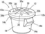
- FIG. 3 is an external perspective view showing the cushion clip in the first embodiment.
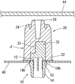
- the longitudinal cross-sectional view showing the cushion clip of FIG. The external appearance perspective view showing the clip body in the cushion clip of FIG.
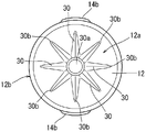
- the top view showing the clip body of FIG. FIG. 6 is an external perspective view showing a cushion clip in a second embodiment.
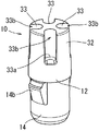
- the longitudinal cross-sectional view showing the cushion clip of FIG. The external appearance perspective view showing the clip body in the cushion clip of FIG.
- the top view showing the clip body of FIG. FIG. 6 is an external perspective view showing a cushion clip in a third embodiment.
- the longitudinal cross-sectional view showing the cushion clip of FIG. The external appearance perspective view showing the clip body in the cushion clip of FIG. FIG. 6 is an external perspective view showing a cushion clip in a fourth embodiment.
- the longitudinal cross-sectional view showing the cushion clip of FIG. The external appearance perspective view showing the clip body in the cushion clip of FIG.
- FIGS. 1 and 2 The cushion clip shown in FIGS. 1 and 2 is attached to the vehicle body side member 40 at the door opening / closing location of the automobile (FIG. 2), and absorbs the impact when the door member 44 is closed. That is, the vehicle body side member 40 and the door member 44 correspond to the “fixed member” and the “movable member” of the present invention.
- the cushion clip may be attached to the door member 44 (movable member) depending on the use location.
- the structure of the cushion clip is roughly divided into a clip body 10 formed of a hard resin material such as polypropylene (PP) and a cushion body 20 formed of a soft resin material such as elastomer. And the clip body 10 and the cushion body 20 are integrally couple
- the clip body 10 is provided for attaching the cushion clip to the vehicle body side member 40, and the cushion body 20 is provided for receiving the door member 44 and absorbing the impact.
- the clip body 10 has a disk-shaped base portion 12, from which a cylindrical anchor portion 14 projects downward.
- the base portion 12 is a portion constituting the joint portion J on the clip body 10 side, and a plurality of ribs 30 constituting an uneven shape are formed on the surface 12a. These ribs 30 extend radially from the central protrusion 30a located at the center of the surface 12a (FIGS. 3 and 4).
- the cross-sectional shape of each rib 30 is a triangle, and the cross-sectional area decreases from the central protrusion 30a toward each tip 30b.
- the anchor portion 14 can be inserted into a mounting hole 42 that is previously opened in the vehicle body side member 40 (FIG. 2), and the outer wall surface 14 a becomes a tapered surface whose diameter decreases from the base portion 12 toward the tip. ing. Further, locking claws 14b are located on both sides of the anchor portion 14, respectively. These locking claws 14 b are pushed and bent inward as the anchor portion 14 is inserted into the mounting hole 42 of the vehicle body side member 40, pass through the mounting hole 42, and are attached inside the vehicle body side member 40. Locks to the edge of the hole 42 (FIG. 2). As a result, the clip body 10 is coupled to the vehicle body side member 40.
- the cushion body 20 is a portion where the bottom portion 22 forms a joint portion J with the base portion 12 of the clip body 10, and the top portion 24 is a portion that receives the door member 44.
- a circular opening 26 for tuning the elastic characteristics of the cushion body 20 is provided in the center of the top portion 24. That is, the flexibility when the cushion body 20 absorbs an impact can be adjusted by changing the plane area and depth of the opening 26.
- the clip body 10 and the cushion body 20 are integrally coupled to each other at the joint portion J by two-color molding using individual resin materials as described above. That is, in the joint portion J, the surface 12 a and the peripheral surface 12 b of the base portion 12 in the clip body 10 are integrated with each other in a state of being wrapped by the bottom portion 22 of the cushion body 20.
- the clip body 10 is made of PP suitable for maintaining the mounting strength with respect to the vehicle body side member 40
- the cushion body 20 is made of elastomer suitable for shock absorption. Can be used.
- the base portion 12 of the clip body 10 in the joint portion J has an uneven shape formed by the plurality of ribs 30 formed on the surface 12a.
- the contact area of the base part 12 of the clip body 10 and the bottom part 22 of the cushion body 20 increases. Therefore, the adhesive force between the clip body 10 and the cushion body 20 at the joint portion J can be increased in a space restricted by the maximum diameter of the cushion body 20 or the mounting hole 42 of the vehicle body side member 40.
- the clip body 10 and the cushion body 20 are two-color molded, the clip body 10 is usually molded first with, for example, PP, and then the cushion body 20 is made of, for example, an elastomer with a mold having its base 12 set in the mold. Injection molding.
- the tip 30b having a small cross-sectional area of each rib 30 is melted by the heat of the elastomer, and the PP is irregularly infiltrated into the elastomer. Thereby, the adhesive force of the clip body 10 and the cushion body 20 in the junction part J is raised more.
- the clip body 10 is coupled to the vehicle body side member 40 by inserting the anchor portion 14 of the clip body 10 into the mounting hole 42 of the vehicle body side member 40, and as a result, the cushion clip is attached to the vehicle body side member 40. It is attached (FIG. 2). Therefore, when the door member 44 is closed, the door member 44 is received by the cushion body 20, and the impact is absorbed by the compression deformation of the cushion body 20. Repeating such elastic deformation of the cushion body 20 promotes mutual peeling at the joint J between the clip body 10 and the cushion body 20 and exerts a force. However, since the contact area between the clip body 10 and the cushion body 20 at the joint portion J is increased as described above, the joined state of the joint portion J is maintained.
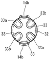
- the cushion clip shown in these drawings includes a vertically long cushion body 20 as compared with the cushion clip in the first embodiment described above or the third and fourth embodiments described later. Therefore, the base portion 12 of the clip body 10 has a columnar extension portion 32 that has entered the inside of the cushion body 20, and a plurality of notches 33 that form an uneven shape are provided on the outer peripheral portion thereof (FIG. 7). And FIG. 8). Each notch 33 is an open surface 33b except for the individual bottom surface 33a, and each open surface 33b is open at the peripheral surface and the end surface of the extension portion 32.
- the cushion body 20 according to the second embodiment includes a cylindrical low buffer portion 28 that protrudes from the top 24 thereof. The low buffer portion 28 first receives and deforms the door member 44 of FIG. 6, and then the main body portion of the cushion body 20 is deformed to absorb the impact.
- each notch 33 of the extension part 32 contains an elastomer or the like as a material of the cushion body 20, and the contact area between the clip body 10 and the cushion body 20 is increased. Therefore, the adhesive force between the clip body 10 and the cushion body 20 at the joint portion J can be increased.
- the bottom surface 33a of each notch 33 prevents the elastomer or the like that has entered each notch 33 from flowing out of the mold, that is, to the anchor portion 14 during the above-described injection molding of the cushion body 20.
- the concave and convex shape of the base portion 12 is set by integrally forming a flange 34 protruding from the outer periphery of the base portion 12 of the clip body 10. Due to the uneven shape, a step is generated between the outer peripheral portion of the base 12 and the flange 34, which is wrapped with an elastomer which is a material of the cushion body 20 (FIG. 10). That is, at the joint J between the clip body 10 and the cushion body 20, the elastomer wraps around from the front surface side of the flange 34 to the back surface (lower surface) side (FIG. 10). For this reason, in addition to an increase in mutual contact area at the joint portion J, the base portion 12 of the clip body 10 and the bottom portion 22 of the cushion body 20 are physically coupled, and the mutual is more firmly integrated.
- a flange 34 is integrally formed on the base portion 12, and a plurality of holes that penetrate through the front and back of the flange 34 are also provided.
- the concavo-convex shape of the base 12 is set by opening the through hole 36.
- the through holes 36 are arranged along the circumferential direction near the outer periphery of the flange 34.
Landscapes
- Engineering & Computer Science (AREA)
- General Engineering & Computer Science (AREA)
- Health & Medical Sciences (AREA)
- Child & Adolescent Psychology (AREA)
- Mechanical Engineering (AREA)
- Vibration Dampers (AREA)
- Insertion Pins And Rivets (AREA)
- Springs (AREA)
Abstract
Description
固定部材に接近してくる可動部材の動きを受け止めて衝撃を吸収するために、固定部材あるいは可動部材のいずれかに形成された取付け孔に挿入して取り付けられるクリップ体と、弾性変形によって衝撃を吸収するクッション体とを備えたクッションクリップであって、硬質の樹脂材からなるクリップ体と軟質の樹脂材からなるクッション体とが、相互の接合部において二色成形で一体的に結合されている。そして、この接合部でのクリップ体が、クッション体の内部に入り込んだ基部を備えているとともに、この基部に対してクッション体との接触面積を増加させるための凹凸形状が設定されている。
これにより、クリップ体を挿入する取付け孔の内径やクッション体の最大径などによって制約されたスペース内において、両者の接合部での接着力を高めることができる。
この構成では、複数のリブによってクリップ体とクッション体との接合部における接触面積が増加する。さらに、二色成形に際してクリップ体を成形した後、クッション体を成形して相互を結合するときに、樹脂材の熱によって相互の接合部ではリブの一部が溶融してクッション体の樹脂材に浸入することになり、接合部の接着力がより高められる。
この構成によれば、クリップ体とクッション体との接合部では、柱状の基部がクッション体の内部に位置し、かつ、基部の外周にある複数の切り欠きにクッション体の樹脂材が入り込むことになり、クリップ体とクッション体との接触面積が増加して接合部の接着力がより高められる。
この構成にあっては、クッション体の樹脂材がクリップ体における基部のフランジを包み込む状態になり、クリップ体とクッション体との接触面積が増加することに加え、相互の物理的な結合が得られる。
この構成によれば、クリップ体における基部のフランジを包み込んだ状態で、該フランジの表裏両側に位置するクッション体の樹脂材が各透孔を通じて繋がることから、さらに強力なクリップ体とクッション体との物理的な結合が得られる。
まず、本発明における実施の形態1を図1~図4によって説明する。
図1および図2で示すクッションクリップは、自動車のドア開閉箇所における車体側部材40に取り付けられ(図2)、ドア部材44を閉めたときの衝撃を吸収する。つまり、この車体側部材40およびドア部材44が、本発明の「固定部材」および「可動部材」に相当する。なお、クッションクリップは、その使用箇所によってはドア部材44(可動部材)に取り付けられる場合もある。
また、クリップ体10とクッション体20との二色成形に際しては、通常はクリップ体10を例えばPPで先に成形した後、その基部12を型内にセットした金型によってクッション体20を例えばエラストマーで射出成形する。このクッション体20の成形時に、各リブ30の断面積の小さい先端部30bなどがエラストマーの熱によって溶融し、PPがエラストマーの中に不規則に浸入した状態になる。これにより、接合部Jでのクリップ体10とクッション体20との接着力がより高められる。
このようなクッション体20の弾性変形が繰り返されることで、クリップ体10とクッション体20との接合部Jには相互の剥離を促進させ力が働くことになる。しかし、前述のように接合部Jでのクリップ体10とクッション体20との接触面積を増加させているので、接合部Jの結合状態は維持される。
これらの図面で示すクッションクリップは、前述の実施の形態1あるいは後述の実施の形態3,4におけるクッションクリップと比較して、縦長形状のクッション体20を備えている。そこで、クリップ体10の基部12は、クッション体20の内部に入り込んだ柱状の延長部32を有し、その外周部には凹凸形状を構成する複数の切り欠き33が設けられている(図7および図8)。各切り欠き33は、個々の底面33aを除いて開放面33bになっており、それぞれの開放面33bは延長部32の周面ならびに端面で開放されている。
なお、実施の形態2のクッション体20は、その頂部24から突出した筒形状の低緩衝部28を備えている。この低緩衝部28は、図6のドア部材44を最初に受け止めて変形し、その後にクッション体20の本体部分が変形して衝撃を吸収する。
各切り欠き33の底面33aは、前述したクッション体20の射出成形時において、個々の切り欠き33に入ったエラストマーなどが金型の外、つまりアンカー部14の側に流出するのを阻止する。
これらの図面で示すクッションクリップにあっては、クリップ体10の基部12にその外周から張り出したフランジ34を一体に成形することで、該基部12の凹凸形状が設定されている。この凹凸形状によって基部12の外周部とフランジ34との間に段差が生じており、ここをクッション体20の素材であるエラストマーで包み込むことになる(図10)。
つまり、クリップ体10とクッション体20との接合部Jにおいては、エラストマーがフランジ34の表面側から裏面(下面)側に回り込んでいる(図10)。このため、接合部Jにおける相互の接触面積が増加することに加え、クリップ体10の基部12とクッション体20の底部22とが物理的に結合され、相互がより強固に一体化される。
これらの図面で示すクッションクリップでは、前述の実施の形態3におけるクリップ体10と同様に、その基部12にフランジ34が一体に成形され、さらに該フランジ34に対して、その表裏に貫通する複数個の透孔36を開けることで、基部12の凹凸形状が設定されている。なお、各透孔36はフランジ34の外周寄りにおいて周方向に沿って配列されている。
これにより、実施の形態3の場合と同様に基部12の外周部とフランジ34との間に段差があるとともに、この段差の近傍においてフランジ34の表面側と裏面側とが各透孔36によって連通している。したがって、クリップ体10とクッション体20との接合部Jにおいては、フランジ34の表面側から裏面側に回り込んだエラストマーが各透孔36を通じて繋がることになる(図13)。この結果、クリップ体10の基部12とクッション体20の底部22とが物理的に結合が実施の形態3の場合よりも、さらに強力となる。
12 基部
12a 表面
20 クッション体
22 底部
J 接合部
30 リブ(凹凸形状)
40 車体側部材(固定部材)
42 取付け孔
44 ドア部材(可動部材)
Claims (5)
- 固定部材に接近してくる可動部材の動きを受け止めて衝撃を吸収するために、固定部材あるいは可動部材のいずれかに形成された取付け孔に挿入して取り付けられるクリップ体と、弾性変形によって衝撃を吸収するクッション体とを備えたクッションクリップであって、
硬質の樹脂材からなるクリップ体と軟質の樹脂材からなるクッション体とが、相互の接合部において二色成形で一体的に結合されており、この接合部でのクリップ体が、クッション体の内部に入り込んだ基部を備えているとともに、この基部に対してクッション体との接触面積を増加させるための凹凸形状が設定されているクッションクリップ。 - 請求項1に記載されたクッションクリップであって、
接合部におけるクリップ体の基部は板状で、その表面に複数のリブを一体に成形することで凹凸形状が設定されているクッションクリップ。 - 請求項1に記載されたクッションクリップであって、
接合部におけるクリップ体の基部は柱状で、その外周に複数の切り欠きを成形することで凹凸形状が設定されているクッションクリップ。 - 請求項1に記載されたクッションクリップであって、
接合部におけるクリップ体の基部は板状で、この基部の表面側にその外周から張り出したフランジを一体に成形することで凹凸形状が設定されているクッションクリップ。 - 請求項4に記載されたクッションクリップであって、
クリップ体における基部のフランジに、その表裏に貫通する複数個の透孔が開けられているクッションクリップ。
Priority Applications (5)
| Application Number | Priority Date | Filing Date | Title |
|---|---|---|---|
| CN200980126156.1A CN102089547B (zh) | 2008-07-04 | 2009-07-03 | 缓冲夹 |
| AU2009266714A AU2009266714B2 (en) | 2008-07-04 | 2009-07-03 | Cushion clip |
| EP09773572.4A EP2306042A4 (en) | 2008-07-04 | 2009-07-03 | DAMPER CLAMP |
| US13/002,468 US20110167590A1 (en) | 2008-07-04 | 2009-07-03 | Cushion clip |
| US29/488,624 USD779313S1 (en) | 2008-07-04 | 2014-04-22 | Cushion clip |
Applications Claiming Priority (2)
| Application Number | Priority Date | Filing Date | Title |
|---|---|---|---|
| JP2008-175660 | 2008-07-04 | ||
| JP2008175660A JP2010014216A (ja) | 2008-07-04 | 2008-07-04 | クッションクリップ |
Related Child Applications (2)
| Application Number | Title | Priority Date | Filing Date |
|---|---|---|---|
| US13/002,468 A-371-Of-International US20110167590A1 (en) | 2008-07-04 | 2009-07-03 | Cushion clip |
| US29/488,624 Continuation USD779313S1 (en) | 2008-07-04 | 2014-04-22 | Cushion clip |
Publications (1)
| Publication Number | Publication Date |
|---|---|
| WO2010001994A1 true WO2010001994A1 (ja) | 2010-01-07 |
Family
ID=41466084
Family Applications (1)
| Application Number | Title | Priority Date | Filing Date |
|---|---|---|---|
| PCT/JP2009/062204 Ceased WO2010001994A1 (ja) | 2008-07-04 | 2009-07-03 | クッションクリップ |
Country Status (6)
| Country | Link |
|---|---|
| US (2) | US20110167590A1 (ja) |
| EP (1) | EP2306042A4 (ja) |
| JP (1) | JP2010014216A (ja) |
| CN (1) | CN102089547B (ja) |
| AU (1) | AU2009266714B2 (ja) |
| WO (1) | WO2010001994A1 (ja) |
Cited By (2)
| Publication number | Priority date | Publication date | Assignee | Title |
|---|---|---|---|---|
| US20110283490A1 (en) * | 2010-05-21 | 2011-11-24 | Daiwa Kasei Kogyo Kabushiki Kaisha | Cushion clip |
| JP2012180897A (ja) * | 2011-03-01 | 2012-09-20 | Mazda Motor Corp | 介在部材の保持構造、介在部材、及びがたつき防止部材 |
Families Citing this family (27)
| Publication number | Priority date | Publication date | Assignee | Title |
|---|---|---|---|---|
| JP2010014216A (ja) * | 2008-07-04 | 2010-01-21 | Daiwa Kasei Kogyo Kk | クッションクリップ |
| JP5154459B2 (ja) * | 2009-01-19 | 2013-02-27 | 大和化成工業株式会社 | クッションクリップ |
| JP2011027209A (ja) * | 2009-07-28 | 2011-02-10 | Daiwa Kasei Kogyo Kk | クッションクリップ |
| JP5666368B2 (ja) * | 2011-03-31 | 2015-02-12 | 大和化成工業株式会社 | 緩衝クリップ |
| DE112012006016B4 (de) * | 2012-03-12 | 2024-08-01 | Piolax Inc. | Vorspannvorrichtung |
| CN104520605B (zh) * | 2012-08-07 | 2016-12-14 | 百乐仕株式会社 | 缓冲装置 |
| CN103437625A (zh) * | 2013-08-20 | 2013-12-11 | 重庆长安汽车股份有限公司 | 一种车门缓冲构件 |
| JP2015110999A (ja) * | 2013-11-06 | 2015-06-18 | 大和化成工業株式会社 | クリップ |
| JP6328476B2 (ja) * | 2014-04-16 | 2018-05-23 | 大和化成工業株式会社 | クリップ |
| USD777019S1 (en) * | 2014-05-08 | 2017-01-24 | Daiwa Kasei Kogyo Kabushiki Kaisha | Cushion |
| US9181745B1 (en) | 2014-05-21 | 2015-11-10 | Newfrey Llc | Trunk cushion assembly |
| WO2016121583A1 (ja) * | 2015-01-26 | 2016-08-04 | 株式会社パイオラックス | ストッパ装置 |
| GB2537615B (en) * | 2015-04-20 | 2019-11-20 | Ford Global Tech Llc | A bump stop assembly |
| US9873389B2 (en) * | 2015-07-10 | 2018-01-23 | Daiwa Kasei Industry Co., Ltd. | Vehicle cushion component |
| USD786054S1 (en) * | 2015-08-25 | 2017-05-09 | Daiwa Kasei Kogyo Kabushiki Kaisha | Clip |
| CN106870614A (zh) * | 2017-02-27 | 2017-06-20 | 北京汽车研究总院有限公司 | 一种减震器及车辆 |
| CN108146541B (zh) * | 2018-01-10 | 2024-03-29 | 延锋彼欧汽车外饰系统有限公司 | 一种缓冲垫匹配结构 |
| CN110043142B (zh) * | 2018-01-15 | 2021-07-20 | 宝沃汽车(中国)有限公司 | 车门锁扣及具有其的车辆 |
| FR3079594B1 (fr) * | 2018-03-30 | 2020-03-06 | A. Raymond Et Cie | Dispositif d'ajustement de l'elevation d'une piece |
| TWD203911S (zh) * | 2019-09-06 | 2020-04-11 | 仟昇工業股份有限公司 | 千斤頂之支撐台 |
| USD1064800S1 (en) * | 2022-06-27 | 2025-03-04 | Zhejiang Feitian Optoelectronic Co., Ltd. | Hook |
| US12123250B2 (en) * | 2022-07-01 | 2024-10-22 | Illinois Tool Works Inc. | Fasteners |
| JP7851482B2 (ja) * | 2023-03-31 | 2026-04-24 | 本田技研工業株式会社 | 緩衝部材取付構造 |
| USD1056691S1 (en) * | 2024-08-28 | 2025-01-07 | Bing Long | Hanging hook |
| USD1056692S1 (en) * | 2024-08-28 | 2025-01-07 | Bing Long | Hanging hook |
| USD1060016S1 (en) * | 2024-08-28 | 2025-02-04 | Bing Long | Hanging hook |
| USD1055678S1 (en) * | 2024-09-14 | 2024-12-31 | Feelinghi Trade (Guangzhou) Co., ltd. | Hanging hook |
Citations (5)
| Publication number | Priority date | Publication date | Assignee | Title |
|---|---|---|---|---|
| JPH10323860A (ja) * | 1997-05-27 | 1998-12-08 | Hitachi Maxell Ltd | 二色成形品と二色成形用金型 |
| JP2003130110A (ja) | 2001-10-30 | 2003-05-08 | Nippon Stud Welding Co Ltd | クッション |
| JP2003214470A (ja) * | 2002-01-17 | 2003-07-30 | Nifco Inc | 緩衝クリップ |
| JP2005186542A (ja) * | 2003-12-26 | 2005-07-14 | Idemitsu Kosan Co Ltd | 多色成形品、およびその成形方法 |
| JP2006052806A (ja) * | 2004-08-13 | 2006-02-23 | Daiwa Kasei Ind Co Ltd | クッションクリップ |
Family Cites Families (33)
| Publication number | Priority date | Publication date | Assignee | Title |
|---|---|---|---|---|
| US272531A (en) * | 1883-02-20 | Door-check | ||
| US2703428A (en) * | 1949-06-21 | 1955-03-08 | Automotive Spring Company | Cushion head pin |
| US2813712A (en) * | 1953-09-30 | 1957-11-19 | Studebaker Packard Corp | Rubber bumpers |
| USD372419S (en) * | 1989-11-01 | 1996-08-06 | Toshiroh Ikegami | Coupling element for furniture |
| US5482348A (en) * | 1993-07-12 | 1996-01-09 | Ford Motor Company | Vehicle hood support post member |
| US5419539A (en) * | 1993-08-16 | 1995-05-30 | Freudenberg-Nok General Partnership | Elastomeric shock absorber with positioning insert |
| KR19980027994A (ko) * | 1996-10-18 | 1998-07-15 | 박병재 | 자동차의 후드 오버슬램범퍼 완충장치 |
| US5742982A (en) * | 1996-11-25 | 1998-04-28 | Siecor Corporation | Cable strain relief apparatus |
| USD395815S (en) * | 1997-06-16 | 1998-07-07 | Siecor Corporation | Spacer for optical fiber cables |
| USD412435S (en) * | 1997-07-16 | 1999-08-03 | Harley-Davidson Motor Company | Axle nut cover |
| US6295697B1 (en) * | 1999-07-30 | 2001-10-02 | Triangle Brass Manufacturing Co. | Vandal-resistant wall-bumper |
| IT1321053B1 (it) * | 2000-11-09 | 2003-12-30 | Fiat Auto Spa | Tampone di battuta regolabile per una parte mobile della carrozzeriadi un autoveicolo. |
| US6857166B2 (en) * | 2001-11-13 | 2005-02-22 | Toyoda Gosei Co., Ltd. | Cushion |
| JP2003202043A (ja) * | 2002-01-08 | 2003-07-18 | Daiwa Kasei Ind Co Ltd | 緩衝クリップ |
| US6710249B1 (en) * | 2002-09-13 | 2004-03-23 | Sandra L. Denton | Wire separator |
| US7017239B2 (en) * | 2002-12-17 | 2006-03-28 | Illinois Tool Works Inc. | Component connection system |
| US20040139575A1 (en) * | 2003-01-17 | 2004-07-22 | Kargilis John S. | Vehicle bumper and method of attachment |
| US6974292B2 (en) * | 2003-10-30 | 2005-12-13 | Illinois Tool Works Inc | One-piece reusable plastic fastener |
| KR100565371B1 (ko) * | 2004-06-09 | 2006-03-28 | 현대모비스 주식회사 | 글로브 박스용 단차조절 가능 범퍼 |
| DE202004012733U1 (de) * | 2004-08-13 | 2004-10-21 | Böllhoff Verbindungstechnik GmbH | Einstelleinheit zum Einstellen des Abstandes zwischen zwei Bauteilen |
| DE102004055638A1 (de) * | 2004-11-18 | 2006-05-24 | Ejot Gmbh & Co. Kg | Elastischer Anschlagpuffer, insbesondere für Verschlussdeckel |
| JP2006153083A (ja) * | 2004-11-26 | 2006-06-15 | Daiwa Kasei Ind Co Ltd | 緩衝クリップ |
| US7469445B2 (en) * | 2005-06-28 | 2008-12-30 | Gm Global Technology Operations, Inc. | Adjustable bumper for door |
| JP2007162733A (ja) * | 2005-12-09 | 2007-06-28 | Daiwa Kasei Ind Co Ltd | クッション部材およびクッション部材の成形方法 |
| JP2007225093A (ja) * | 2006-02-27 | 2007-09-06 | Daiwa Kasei Ind Co Ltd | クッションクリップ |
| JP4898389B2 (ja) * | 2006-10-27 | 2012-03-14 | 大和化成工業株式会社 | 車両用クッションクリップ |
| JP2010014216A (ja) * | 2008-07-04 | 2010-01-21 | Daiwa Kasei Kogyo Kk | クッションクリップ |
| USD642901S1 (en) * | 2009-12-08 | 2011-08-09 | Hon Hai Precision Industry Co., Ltd. | Bolt |
| USD632163S1 (en) * | 2010-03-17 | 2011-02-08 | Greenland Composites, Inc. | Four-way coupling |
| JP2011241962A (ja) * | 2010-05-21 | 2011-12-01 | Daiwa Kasei Kogyo Kk | 緩衝クリップ |
| JP5666368B2 (ja) * | 2011-03-31 | 2015-02-12 | 大和化成工業株式会社 | 緩衝クリップ |
| CN104520605B (zh) * | 2012-08-07 | 2016-12-14 | 百乐仕株式会社 | 缓冲装置 |
| JP5847769B2 (ja) * | 2012-12-18 | 2016-01-27 | 八千代工業株式会社 | 燃料タンク用緩衝部材 |
-
2008
- 2008-07-04 JP JP2008175660A patent/JP2010014216A/ja active Pending
-
2009
- 2009-07-03 WO PCT/JP2009/062204 patent/WO2010001994A1/ja not_active Ceased
- 2009-07-03 EP EP09773572.4A patent/EP2306042A4/en not_active Withdrawn
- 2009-07-03 US US13/002,468 patent/US20110167590A1/en not_active Abandoned
- 2009-07-03 CN CN200980126156.1A patent/CN102089547B/zh active Active
- 2009-07-03 AU AU2009266714A patent/AU2009266714B2/en not_active Ceased
-
2014
- 2014-04-22 US US29/488,624 patent/USD779313S1/en active Active
Patent Citations (5)
| Publication number | Priority date | Publication date | Assignee | Title |
|---|---|---|---|---|
| JPH10323860A (ja) * | 1997-05-27 | 1998-12-08 | Hitachi Maxell Ltd | 二色成形品と二色成形用金型 |
| JP2003130110A (ja) | 2001-10-30 | 2003-05-08 | Nippon Stud Welding Co Ltd | クッション |
| JP2003214470A (ja) * | 2002-01-17 | 2003-07-30 | Nifco Inc | 緩衝クリップ |
| JP2005186542A (ja) * | 2003-12-26 | 2005-07-14 | Idemitsu Kosan Co Ltd | 多色成形品、およびその成形方法 |
| JP2006052806A (ja) * | 2004-08-13 | 2006-02-23 | Daiwa Kasei Ind Co Ltd | クッションクリップ |
Non-Patent Citations (1)
| Title |
|---|
| See also references of EP2306042A4 |
Cited By (4)
| Publication number | Priority date | Publication date | Assignee | Title |
|---|---|---|---|---|
| US20110283490A1 (en) * | 2010-05-21 | 2011-11-24 | Daiwa Kasei Kogyo Kabushiki Kaisha | Cushion clip |
| US8407857B2 (en) * | 2010-05-21 | 2013-04-02 | Daiwa Kasei Kogyo Kabushiki Kaisha | Cushion clip |
| JP2012180897A (ja) * | 2011-03-01 | 2012-09-20 | Mazda Motor Corp | 介在部材の保持構造、介在部材、及びがたつき防止部材 |
| US9212736B2 (en) | 2011-03-01 | 2015-12-15 | Nifco Inc. | Holding structure of intervening member, intervening member, and wobbling-prevention member |
Also Published As
| Publication number | Publication date |
|---|---|
| US20110167590A1 (en) | 2011-07-14 |
| EP2306042A4 (en) | 2014-06-18 |
| EP2306042A1 (en) | 2011-04-06 |
| AU2009266714B2 (en) | 2013-06-06 |
| CN102089547B (zh) | 2013-03-27 |
| CN102089547A (zh) | 2011-06-08 |
| JP2010014216A (ja) | 2010-01-21 |
| AU2009266714A1 (en) | 2010-01-07 |
| USD779313S1 (en) | 2017-02-21 |
Similar Documents
| Publication | Publication Date | Title |
|---|---|---|
| JP2010014216A (ja) | クッションクリップ | |
| JP6328476B2 (ja) | クリップ | |
| US7762375B2 (en) | Soundproofing material | |
| JP5154459B2 (ja) | クッションクリップ | |
| JP6147508B2 (ja) | クッションクリップ | |
| JP2011027209A (ja) | クッションクリップ | |
| RU2667441C2 (ru) | Магнитный крепежный узел и несущий элемент для удержания магнитного крепежного подузла | |
| KR20210131002A (ko) | 자동차용 펜더 인슐레이션의 제조방법 | |
| JP2013147939A (ja) | エンジンカバー | |
| JP2002349524A (ja) | 緩衝クリップとその成形方法 | |
| JP2008094261A (ja) | クッションクリップ | |
| JPH06239189A (ja) | 車両用内装部品の取付構造 | |
| JP2004252169A (ja) | 中空構造物の中空室遮断具 | |
| JP3719888B2 (ja) | バンパーラバー | |
| KR100757608B1 (ko) | 차량의 도어 트림 패드 장착 구조 | |
| KR20200050083A (ko) | 도어트림용 파스너 | |
| JP3700580B2 (ja) | 配管のクランプ | |
| JP2013095271A (ja) | 車両用窓板の装飾部材 | |
| CN107524364A (zh) | 用于车辆结构件的缓冲件及约束组件 | |
| JP5691287B2 (ja) | 発泡成形部材、その取付用クリップ、発泡成形部材の製造方法並びに発泡成形部材の取付構造 | |
| JP6339614B2 (ja) | バウンドストッパ | |
| JP2017100511A (ja) | 車両用バックドア | |
| JP2021169844A (ja) | クッションクリップ | |
| US10786049B2 (en) | Housing for a belt buckle | |
| JP6747890B2 (ja) | 車両用緩衝部品 |
Legal Events
| Date | Code | Title | Description |
|---|---|---|---|
| WWE | Wipo information: entry into national phase |
Ref document number: 200980126156.1 Country of ref document: CN |
|
| 121 | Ep: the epo has been informed by wipo that ep was designated in this application |
Ref document number: 09773572 Country of ref document: EP Kind code of ref document: A1 |
|
| NENP | Non-entry into the national phase |
Ref country code: DE |
|
| WWE | Wipo information: entry into national phase |
Ref document number: 2009773572 Country of ref document: EP |
|
| WWE | Wipo information: entry into national phase |
Ref document number: 2009266714 Country of ref document: AU |
|
| WWE | Wipo information: entry into national phase |
Ref document number: 880/DELNP/2011 Country of ref document: IN |
|
| ENP | Entry into the national phase |
Ref document number: 2009266714 Country of ref document: AU Date of ref document: 20090703 Kind code of ref document: A |
|
| WWE | Wipo information: entry into national phase |
Ref document number: 13002468 Country of ref document: US |