WO2010005205A2 - Plaque de condensateur à diffusion élevée et ensemble de rétroéclairage utilisant ladite plaque - Google Patents
Plaque de condensateur à diffusion élevée et ensemble de rétroéclairage utilisant ladite plaque Download PDFInfo
- Publication number
- WO2010005205A2 WO2010005205A2 PCT/KR2009/003607 KR2009003607W WO2010005205A2 WO 2010005205 A2 WO2010005205 A2 WO 2010005205A2 KR 2009003607 W KR2009003607 W KR 2009003607W WO 2010005205 A2 WO2010005205 A2 WO 2010005205A2
- Authority
- WO
- WIPO (PCT)
- Prior art keywords
- light
- diffusion
- sheet
- base layer
- condensing lens
- Prior art date
- Legal status (The legal status is an assumption and is not a legal conclusion. Google has not performed a legal analysis and makes no representation as to the accuracy of the status listed.)
- Ceased
Links
Images


Classifications
-
- G—PHYSICS
- G02—OPTICS
- G02B—OPTICAL ELEMENTS, SYSTEMS OR APPARATUS
- G02B5/00—Optical elements other than lenses
- G02B5/02—Diffusing elements; Afocal elements
- G02B5/0273—Diffusing elements; Afocal elements characterized by the use
- G02B5/0278—Diffusing elements; Afocal elements characterized by the use used in transmission
-
- C—CHEMISTRY; METALLURGY
- C08—ORGANIC MACROMOLECULAR COMPOUNDS; THEIR PREPARATION OR CHEMICAL WORKING-UP; COMPOSITIONS BASED THEREON
- C08J—WORKING-UP; GENERAL PROCESSES OF COMPOUNDING; AFTER-TREATMENT NOT COVERED BY SUBCLASSES C08B, C08C, C08F, C08G or C08H
- C08J5/00—Manufacture of articles or shaped materials containing macromolecular substances
- C08J5/18—Manufacture of films or sheets
-
- G—PHYSICS
- G02—OPTICS
- G02B—OPTICAL ELEMENTS, SYSTEMS OR APPARATUS
- G02B5/00—Optical elements other than lenses
- G02B5/02—Diffusing elements; Afocal elements
- G02B5/0205—Diffusing elements; Afocal elements characterised by the diffusing properties
- G02B5/021—Diffusing elements; Afocal elements characterised by the diffusing properties the diffusion taking place at the element's surface, e.g. by means of surface roughening or microprismatic structures
- G02B5/0221—Diffusing elements; Afocal elements characterised by the diffusing properties the diffusion taking place at the element's surface, e.g. by means of surface roughening or microprismatic structures the surface having an irregular structure
-
- G—PHYSICS
- G02—OPTICS
- G02F—OPTICAL DEVICES OR ARRANGEMENTS FOR THE CONTROL OF LIGHT BY MODIFICATION OF THE OPTICAL PROPERTIES OF THE MEDIA OF THE ELEMENTS INVOLVED THEREIN; NON-LINEAR OPTICS; FREQUENCY-CHANGING OF LIGHT; OPTICAL LOGIC ELEMENTS; OPTICAL ANALOGUE/DIGITAL CONVERTERS
- G02F1/00—Devices or arrangements for the control of the intensity, colour, phase, polarisation or direction of light arriving from an independent light source, e.g. switching, gating or modulating; Non-linear optics
- G02F1/01—Devices or arrangements for the control of the intensity, colour, phase, polarisation or direction of light arriving from an independent light source, e.g. switching, gating or modulating; Non-linear optics for the control of the intensity, phase, polarisation or colour
- G02F1/13—Devices or arrangements for the control of the intensity, colour, phase, polarisation or direction of light arriving from an independent light source, e.g. switching, gating or modulating; Non-linear optics for the control of the intensity, phase, polarisation or colour based on liquid crystals, e.g. single liquid crystal display cells
- G02F1/133—Constructional arrangements; Operation of liquid crystal cells; Circuit arrangements
- G02F1/1333—Constructional arrangements; Manufacturing methods
- G02F1/1335—Structural association of cells with optical devices, e.g. polarisers or reflectors
- G02F1/133524—Light-guides, e.g. fibre-optic bundles, louvered or jalousie light-guides
-
- G—PHYSICS
- G02—OPTICS
- G02F—OPTICAL DEVICES OR ARRANGEMENTS FOR THE CONTROL OF LIGHT BY MODIFICATION OF THE OPTICAL PROPERTIES OF THE MEDIA OF THE ELEMENTS INVOLVED THEREIN; NON-LINEAR OPTICS; FREQUENCY-CHANGING OF LIGHT; OPTICAL LOGIC ELEMENTS; OPTICAL ANALOGUE/DIGITAL CONVERTERS
- G02F1/00—Devices or arrangements for the control of the intensity, colour, phase, polarisation or direction of light arriving from an independent light source, e.g. switching, gating or modulating; Non-linear optics
- G02F1/01—Devices or arrangements for the control of the intensity, colour, phase, polarisation or direction of light arriving from an independent light source, e.g. switching, gating or modulating; Non-linear optics for the control of the intensity, phase, polarisation or colour
- G02F1/13—Devices or arrangements for the control of the intensity, colour, phase, polarisation or direction of light arriving from an independent light source, e.g. switching, gating or modulating; Non-linear optics for the control of the intensity, phase, polarisation or colour based on liquid crystals, e.g. single liquid crystal display cells
- G02F1/133—Constructional arrangements; Operation of liquid crystal cells; Circuit arrangements
- G02F1/1333—Constructional arrangements; Manufacturing methods
- G02F1/1335—Structural association of cells with optical devices, e.g. polarisers or reflectors
- G02F1/133526—Lenses, e.g. microlenses or Fresnel lenses
-
- G—PHYSICS
- G02—OPTICS
- G02F—OPTICAL DEVICES OR ARRANGEMENTS FOR THE CONTROL OF LIGHT BY MODIFICATION OF THE OPTICAL PROPERTIES OF THE MEDIA OF THE ELEMENTS INVOLVED THEREIN; NON-LINEAR OPTICS; FREQUENCY-CHANGING OF LIGHT; OPTICAL LOGIC ELEMENTS; OPTICAL ANALOGUE/DIGITAL CONVERTERS
- G02F1/00—Devices or arrangements for the control of the intensity, colour, phase, polarisation or direction of light arriving from an independent light source, e.g. switching, gating or modulating; Non-linear optics
- G02F1/01—Devices or arrangements for the control of the intensity, colour, phase, polarisation or direction of light arriving from an independent light source, e.g. switching, gating or modulating; Non-linear optics for the control of the intensity, phase, polarisation or colour
- G02F1/13—Devices or arrangements for the control of the intensity, colour, phase, polarisation or direction of light arriving from an independent light source, e.g. switching, gating or modulating; Non-linear optics for the control of the intensity, phase, polarisation or colour based on liquid crystals, e.g. single liquid crystal display cells
- G02F1/133—Constructional arrangements; Operation of liquid crystal cells; Circuit arrangements
- G02F1/1333—Constructional arrangements; Manufacturing methods
- G02F1/1335—Structural association of cells with optical devices, e.g. polarisers or reflectors
- G02F1/1336—Illuminating devices
- G02F1/133602—Direct backlight
- G02F1/133606—Direct backlight including a specially adapted diffusing, scattering or light controlling members
Definitions
- the present invention relates to a backlight, and more particularly, to luminance of light emitted from a light source in a backlight using a fluorescent lamp (CCFL) or a light emitting diode (LED) as a light source.
- the present invention relates to a highly diffused condensing lens sheet having a novel structure for improving uniformity, and a backlight assembly using the same.
- the flat panel display includes a liquid crystal display (LCD), a field emission display (FED), a plasma display panel, and an electroluminescence display (EL). Since the dual liquid crystal display is a non-light emitting device that does not emit light by itself, an external light source such as a backlight is inevitably required.
- LCD liquid crystal display
- FED field emission display
- EL electroluminescence display
- FIG. 1 is a cross-sectional view showing a backlight assembly for a liquid crystal display according to the prior art
- FIG. 2 is a cross-sectional view showing the structure of a light collecting sheet according to the prior art.
- the backlight assembly 20 for a liquid crystal display includes a top plate 12 that is a color filter substrate and a bottom plate 11 that is a thin film transistor (TFT) substrate. Located at the rear of the liquid crystal panel 10 is provided to serve to provide a light source to the liquid crystal panel 10.
- TFT thin film transistor
- the backlight assembly 20 for a liquid crystal display device may include a lamp 21 as a light source for emitting light and a light guide plate 22 for guiding the light emitted from the lamp 21 to the liquid crystal panel 10. , Totally reflecting the light emitted from the lower part of the light guide plate 22 to minimize the loss of light, and an optical sheet 24 to diffuse and collect the light emitted from the upper part of the light guide plate 22 to the liquid crystal panel 10. It is configured to include.
- the diffusion sheet 24a for diffusing the light emitted from the upper portion of the light guide plate 22 at a predetermined angle, and the diffused light to collect and transmit to the liquid crystal panel 10 It comprises the condensing sheet 24b, the diffusion sheet 24a, and the protective sheet 24c which protects the condensing sheet 24b.
- the light collecting sheet 24b is a prism film that collects light in an unnecessary viewing angle region in order to compensate for the frontal luminance of light exiting from the lamp 21 through the light guide plate 22 and the diffusion sheet 24a. That is, it plays a role of collecting the light spread widely at the wide viewing angle by the diffusion sheet (a).
- the light condensing sheet 24b forms a triangular protrusion pattern P having the same size on the upper surface thereof, and the incident light L1, L2, L3, and L4 are applied to the protrusion pattern ( Refraction or total reflection by P) improves the efficiency of the backlight.
- the portions L2 and L3 of the light incident on the light collecting sheet 24b are refracted at a predetermined angle by the protrusion pattern P to pass through the light collecting sheet 24b, and the pitch of the protrusion pattern P
- the linear light L1 incident to picth immediately passes through the light collecting sheet 24b without refraction.
- a part of the light L4 incident on the inclined surface of the protruding pattern P is totally reflected and does not pass through the light collecting sheet 24b and exits to the rear diffusion sheet 24a.
- part of the light L4 incident on the inclined surface of the protrusion pattern P in the conventional light collecting sheet 24b does not contribute to the improvement of the brightness of the front due to total internal reflection and is emitted to the upper / lower side or the side of the screen. There is a problem that a sidelobe phenomenon occurs.
- the present invention has been made to solve the above problems, and to provide a high-diffusion condensing lens sheet of a new structure that can improve the overall light brightness by increasing the light collecting performance of the light emitted from the backlight assembly.
- Another technical problem to be achieved by the present invention is to provide a backlight assembly using a high-diffusion condensing lens sheet having a new structure as described above.
- the base layer forming a base; And a pattern in which lens-shaped protruding surfaces are randomly arrayed on the base layer, and the average diameter of each of the arrayed protruding surfaces is formed to have a size of 71 ⁇ m to 120 ⁇ m to refract or reflect light incident through the base layer. It may include wealth.
- each of the protruding surfaces arranged in the pattern portion may have a different size from each other.
- the base layer may be polyethylene terephthalate (PET) resin, and the pattern portion may be made of acrylic resin.
- PET polyethylene terephthalate
- the thickness including the base layer and the pattern portion may be 350 ⁇ m or less.
- the height of each projecting surface arrayed in the pattern portion may be 50% or less of the diameter of the projecting surface.
- the backlight assembly of the present invention for achieving the above technical problem is characterized in that it comprises a high diffusion condensing lens sheet formed of the above-described structure.
- the optical sheet may have an effect of minimizing efficiency reduction of the light source and securing a wide viewing angle.
- FIG. 1 is a cross-sectional view illustrating a backlight assembly for a liquid crystal display according to the related art.
- FIG. 2 is a cross-sectional view showing the structure of a prism sheet according to the prior art.
- 3 and 4 are cross-sectional views illustrating a configuration of a backlight assembly according to various embodiments of the present disclosure.
- FIG. 5 is a cross-sectional view of a high diffusion condensing lens sheet according to an embodiment of the present invention.
- FIG. 6 is a perspective view of a high diffusion condensing lens sheet according to an embodiment of the present invention.
- FIG. 7 is an enlarged view of region A of FIG. 5.
- FIG. 8 is a graph illustrating a result of measuring luminance according to a lens size of a high-diffusion condensing lens sheet according to an exemplary embodiment of the present invention.
- 9 is an analysis table showing all-light characteristics according to the size of the protruding surface of the high-diffusion condensing lens sheet.
- 3 and 4 are cross-sectional views illustrating a configuration of a backlight assembly according to various embodiments of the present disclosure.
- the backlight assembly may be classified into an edge type or a direct type according to the position of the light source.
- the edge type of the electron is a structure in which a light source is disposed on a side of a light guide plate (LGP).
- LGP light guide plate
- the latter direct type has a structure in which a light source is directly disposed on the rear surface of the liquid crystal panel to supply light to the front surface of the liquid crystal panel.
- the backlight assembly 100 may include a lamp unit 110 generating light and a lamp unit 110.
- the light guide plate 120 for guiding the light toward the liquid crystal display panel, the reflective plate 130 which totally reflects the light emitted from the lower portion of the light guide plate 120 to reduce the loss of light, and diffuses and condenses the light emitted above the light guide plate 120. It is comprised including the optical sheet 140 which exits to a panel (not shown).
- the lamp unit 110 may be configured of a lamp 112 provided on one side or both sides of the light guide plate 120 and a lamp reflector 114 surrounding the lamp 112.
- the light guide plate 120 may be inclined toward the other side from one side where the lamp unit 110 is installed as shown, so that the thickness of the lower surface may be gradually thinner, or may be formed to have the same thickness.
- the reflective plate 130 may be disposed along the lower surface of the light guide plate 120.
- the lamp unit 110 since the lamp unit 110 is positioned at the side of the light guide plate 120, the light generated from the side of the light guide plate 120 is refracted and emitted to the upper liquid crystal panel.
- the backlight assembly 200 of the direct type is similar to the edge type structure of FIG. 3, which is similar to the lamp unit 210, the light guide plate 220, and the reflective plate 230. ), And may include an optical sheet 240.
- the lamp unit 210 generating the light source is located under the light guide plate 220.
- the reflector 230 is positioned below the lamp unit 210 and configured to reflect light leaking backward from the lamp unit 210.
- the light source generated from the lamp unit 210 is emitted directly from the rear of the light guide plate 220 to the front surface.
- the optical sheets 140 and 240 are disposed on the light guide plates 120 and 220 to improve the efficiency of the light output from the light guide plates 120 and 220.
- 240 forms a structure in which the diffusion sheets 141 and 241, the high diffusion condensing lens sheets 143 and 243, and the protective sheets 145 and 245 are sequentially stacked.
- two diffusion sheets and two high-diffusion condenser lens sheets may be configured as needed.
- the diffusion sheet and the high-diffusion condenser lens sheet may be added and removed to be used. It is not limited.
- the diffusion sheets 141 and 241 scatter the light incident from each of the light guide plates 120 and 220 at a predetermined angle to uniform the luminance distribution of the light.
- the high diffusing condenser lens sheets 143 and 243 collect the light diffused through the diffusion sheets 141 and 241 and emit the light toward the front liquid crystal panel. That is, a protruding surface having a predetermined pattern may be provided on a surface facing the diffusion sheets 141 and 241. Therefore, the efficiency of light is improved by refracting or totally reflecting the light incident on the high-diffusion condensing lens sheets 143 and 243 by the protruding surface.
- the protective sheets 145 and 245 are disposed on the high diffusing condensing lens sheets 143 and 243 to protect the surfaces of the high diffusing condensing lens sheets 143 and 243, and at the same time, the high diffusing condensing lens sheets 143 and 243. In order to uniformize the distribution of the light incident from These protective sheets 145 and 245 can be removed as needed.
- FIG. 5 is a cross-sectional view of a high diffusion condensing lens sheet according to an embodiment of the present invention
- FIG. 6 is a perspective view of a high diffusion condensing lens sheet according to an embodiment of the present invention
- FIG. 7 is an enlarged view of a region A of FIG. Drawing.
- the high-diffusion condensing lens sheet 400 has a base layer 410 forming a base of the sheet, and a predetermined pattern on the base layer 410.
- Protruding surfaces 421, 422, and 423 may include an arrayed pattern part 420.
- the high-diffusion condensing lens sheet 400 is provided such that the thickness 400h including the base layer 410 and the pattern portion 420 does not exceed 350 ⁇ m, and the thickness 420h of the pattern portion 420. ) Is provided so as not to exceed 50% of the average diameter of the protruding surfaces 421, 422, 423.
- the base layer 410 may be made of polyethylene terephthalate (PET) resin having excellent light transmittance and a transparent material.
- PET polyethylene terephthalate
- the pattern unit 420 may be formed of an acrylic resin, and other transparent materials may be formed of the same material as the base layer 410 or another material corresponding to the transparent material.
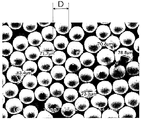
- the pattern part 420 has a plurality of protrusions 421, 422, 423 randomly arranged on one surface of the flat base layer 410, and the plurality of protrusions 421, 422, 423 are provided in a micro lens shape. And the average diameter (D) of the microlenses is formed to have a size of about 71 ⁇ m to about 120 ⁇ m.
- the plurality of projecting surfaces 421, 422, 423 are characterized by having different sizes within the above range.
- the first protrusion 421, the second protrusion 422, and the third protrusion 423 adjacent to each other may have diameters of 75 ⁇ m, 85 ⁇ m, and 73.4 ⁇ m, respectively. At this time, the diameters are all the dimensions included in the range of 71 ⁇ m to 120 ⁇ m.
- the heights 421h, 422h, and 423h of the protruding surfaces 421, 422, and 423 may be 50% or less in the average diameter D of the microlenses.
- the height 421h of the first protrusion 421 is 37.5 ⁇ m or less
- the height 422h of the second protrusion 422 is 42.5 ⁇ m or less
- the height of the third protrusion 423 4523h may be formed to be 36.7 ⁇ m or less.
- the high-diffusion condensing lens sheet 400 configured as described above may be used by stacking two or more of the same sheet by arranging the protrusions 421, 422, and 423 with different diameters D on the pattern portion 420. In this case, it is possible to prevent a moire phenomenon, an optical phenomenon in which a pattern such as a ripple is formed on the screen.
- the heights 421h, 422h, and 423h of the protruding surfaces 421, 422, and 423 are in a range of 50% or less of the average diameter D, thereby significantly reducing the moiré phenomenon occurring when the lenses are stacked. At the same time, the brightness can be increased.
- the luminance according to the size and height of the protruding surface in the high-diffusion condensing lens sheet configured as described above will be measured and compared.
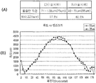
- FIG. 8 is a graph of luminance measured according to the size of the protruding surface of the high diffusing condensing lens sheet according to the embodiment of the present invention, and is a table comparing the high diffusing condensing lens sheet of the present invention with a conventional condensing sheet.
- Example 1 shows a high-diffusion condensing lens sheet of the present invention having an average diameter of the protruding surface in the range of 71 ⁇ m to 120 ⁇ m (for example, a size of 75 ⁇ m), and
- Example 2 of the protruding surface A conventional light collecting sheet having a size (eg, a size of 55 ⁇ m) having an average diameter in the range of 40 ⁇ m to 70 ⁇ m is shown.
- haze was 82.5% for the conventional light collecting sheet (Example 2), while 87.8% for the high-diffusion light collecting lens sheet of the present invention (Example 1).
- the brightness is increased, and it can be seen that the high-diffusion condensing lens sheet (Example 1) of the present invention is improved over the conventional condensing sheet (Example 2).
- the high-diffusion condensing lens sheet (Example 1) of the present invention has a higher luminance than the conventional condensing sheet (Example 2).
- the high dimension of can increase the concealment against defects in appearance.
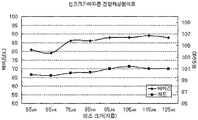
- 9 is an analysis table showing all-light characteristics according to the projecting surface size of the high-diffusion condensing lens sheet.
- the X-axis coordinates represent the projecting surface size of the high-diffusion condensing lens sheet
- the left Y-axis coordinates represent haze values
- the right Y-axis coordinates represent luminance values, respectively.
- the haze value is low when the size of the protruding surface is fine, then rapidly increases from about 70 ⁇ m, and decreases when the size is more than 120 ⁇ m.
- the luminance value can be seen that the size of the protruding surface increases after approximately 70 ⁇ m and decreases from 120 ⁇ m or more.
- the protruding surface when the size of the protruding surface is 70 ⁇ m or less or more than 120 ⁇ m, it has a low luminance value and, of course, a low haze value, so that the diffusivity is low, and thus there is a problem of inferior concealment.
- the size of the protruding surface exceeds 120 ⁇ m, the protruding surface can be visually identified and the thickness of the high-diffusion condensing lens sheet is increased, which causes problems in light and thinning of the product.
- the size of the protruding surface within the range of 71 ⁇ m to 120 ⁇ m has a high brightness value and haze value has the advantage of improving the light efficiency and at the same time minimize the appearance defects due to the improved concealability.
- the high-diffusion condensing lens sheet according to the embodiment of the present invention can obtain improved optical characteristics with respect to luminance and viewing angle by appropriately adjusting the size of the protruding surfaces randomly arranged in the pattern portion within the range of 71 ⁇ m to 120 ⁇ m. have.
Landscapes
- Physics & Mathematics (AREA)
- General Physics & Mathematics (AREA)
- Optics & Photonics (AREA)
- Chemical & Material Sciences (AREA)
- Nonlinear Science (AREA)
- Mathematical Physics (AREA)
- Crystallography & Structural Chemistry (AREA)
- Manufacturing & Machinery (AREA)
- Engineering & Computer Science (AREA)
- Materials Engineering (AREA)
- Health & Medical Sciences (AREA)
- Chemical Kinetics & Catalysis (AREA)
- Medicinal Chemistry (AREA)
- Polymers & Plastics (AREA)
- Organic Chemistry (AREA)
- Optical Elements Other Than Lenses (AREA)
- Planar Illumination Modules (AREA)
- Liquid Crystal (AREA)
Abstract
La présente invention concerne une plaque de condensateur à diffusion élevée destinée à améliorer la luminosité et l'uniformité de la lumière émise par un rétroéclairage, ainsi qu'un ensemble de rétroéclairage utilisant ladite plaque. La plaque de condensateur à diffusion élevée de la présente invention comprend une couche de base constituant une base, et une unité à motifs présentant des surfaces saillantes en forme de lentilles agencées en réseau de manière aléatoire sur la couche de base, chacune des surfaces saillantes présentant des tailles différentes avec un diamètre moyen compris entre 71㎛ et 120㎛.
Applications Claiming Priority (2)
| Application Number | Priority Date | Filing Date | Title |
|---|---|---|---|
| KR1020080066748A KR20100006501A (ko) | 2008-07-09 | 2008-07-09 | 고확산 집광 렌즈 시트 및 이를 이용한 백라이트 어셈블리 |
| KR10-2008-0066748 | 2008-07-09 |
Publications (2)
| Publication Number | Publication Date |
|---|---|
| WO2010005205A2 true WO2010005205A2 (fr) | 2010-01-14 |
| WO2010005205A3 WO2010005205A3 (fr) | 2010-04-22 |
Family
ID=41507558
Family Applications (1)
| Application Number | Title | Priority Date | Filing Date |
|---|---|---|---|
| PCT/KR2009/003607 Ceased WO2010005205A2 (fr) | 2008-07-09 | 2009-07-02 | Plaque de condensateur à diffusion élevée et ensemble de rétroéclairage utilisant ladite plaque |
Country Status (2)
| Country | Link |
|---|---|
| KR (1) | KR20100006501A (fr) |
| WO (1) | WO2010005205A2 (fr) |
Cited By (3)
| Publication number | Priority date | Publication date | Assignee | Title |
|---|---|---|---|---|
| CN104865782A (zh) * | 2014-02-20 | 2015-08-26 | 卡西欧计算机株式会社 | 以激光二极管为光源并具有微镜阵列的光源装置及投影仪 |
| CN110114698A (zh) * | 2016-12-28 | 2019-08-09 | 迪睿合株式会社 | 反射型扩散板、显示装置、投影装置及照明装置 |
| CN111929978A (zh) * | 2020-10-15 | 2020-11-13 | 成都菲斯特科技有限公司 | 一种投影屏幕及投影系统 |
Family Cites Families (3)
| Publication number | Priority date | Publication date | Assignee | Title |
|---|---|---|---|---|
| EP1969578A4 (fr) * | 2005-12-01 | 2010-05-05 | Fujifilm Corp | Feuille optique pour affichage ainsi que procede et appareil de fabrication connexes |
| KR100817838B1 (ko) * | 2006-08-24 | 2008-03-31 | 희성전자 주식회사 | 측면형 백라이트 장치의 도광판 구조 |
| KR20080060406A (ko) * | 2006-12-27 | 2008-07-02 | 삼성전자주식회사 | 광학 시트 및 이를 갖는 표시 장치 |
-
2008
- 2008-07-09 KR KR1020080066748A patent/KR20100006501A/ko not_active Withdrawn
-
2009
- 2009-07-02 WO PCT/KR2009/003607 patent/WO2010005205A2/fr not_active Ceased
Cited By (5)
| Publication number | Priority date | Publication date | Assignee | Title |
|---|---|---|---|---|
| CN104865782A (zh) * | 2014-02-20 | 2015-08-26 | 卡西欧计算机株式会社 | 以激光二极管为光源并具有微镜阵列的光源装置及投影仪 |
| CN110114698A (zh) * | 2016-12-28 | 2019-08-09 | 迪睿合株式会社 | 反射型扩散板、显示装置、投影装置及照明装置 |
| US11002889B2 (en) | 2016-12-28 | 2021-05-11 | Dexerials Corporation | Reflective diffuser plate, display device, projection device, and lighting device |
| CN110114698B (zh) * | 2016-12-28 | 2022-04-05 | 迪睿合株式会社 | 反射型扩散板、显示装置、投影装置及照明装置 |
| CN111929978A (zh) * | 2020-10-15 | 2020-11-13 | 成都菲斯特科技有限公司 | 一种投影屏幕及投影系统 |
Also Published As
| Publication number | Publication date |
|---|---|
| KR20100006501A (ko) | 2010-01-19 |
| WO2010005205A3 (fr) | 2010-04-22 |
Similar Documents
| Publication | Publication Date | Title |
|---|---|---|
| US7246931B2 (en) | LED light source | |
| JP4133420B2 (ja) | バックライト及び液晶表示装置 | |
| US8184235B2 (en) | Optical prism sheet, backlight unit, and liquid crystal display | |
| CN100427976C (zh) | 棱镜片和使用该棱镜片的背光单元 | |
| KR100665871B1 (ko) | 액정표시장치의 백라이트 어셈블리 | |
| WO2011025102A1 (fr) | Dispositif d'affichage à cristaux liquides | |
| CN113495386B (zh) | 照明装置及显示装置 | |
| WO2016186410A1 (fr) | Module de polarisation réfléchissant comportant des particules et unité de rétroéclairage comprenant celui-ci | |
| WO2012039532A1 (fr) | Feuille optique, unité optique et dispositif d'éclairage les utilisant | |
| WO2013032286A1 (fr) | Feuille optique | |
| KR100838681B1 (ko) | 광학 시트, 이를 이용한 백라이트 유닛 및 액정 표시 장치 | |
| WO2010005205A2 (fr) | Plaque de condensateur à diffusion élevée et ensemble de rétroéclairage utilisant ladite plaque | |
| CN110720012A (zh) | 形成有遮蔽部的光传递单元、利用该光传递单元的背光模块以及光传递单元的制造方法 | |
| WO2009151217A2 (fr) | Feuille optique, ensemble de rétroéclairage et dispositif d'affichage à cristaux liquides comprenant la feuille optique | |
| CN1306329C (zh) | 背光模块的光源 | |
| WO2017173703A1 (fr) | Module de rétroéclairage et afficheur à cristaux liquides | |
| CN102162868B (zh) | 一种光学片及具备光学片的背光模组 | |
| TWM409450U (en) | Light guide plate with inner laser engraving | |
| US7954983B2 (en) | Optical component, manufacturing method of the same and backlight module | |
| WO2020171506A1 (fr) | Structure optique pour dispositif à diode électroluminescente et dispositif à diode électroluminescente pour application d'éclairage comprenant celle-ci | |
| WO2010114345A2 (fr) | Plaque de guide de lumière comprenant des particules de diffusion de lumière | |
| WO2014168387A1 (fr) | Élément optique de type prisme inversé | |
| KR101419242B1 (ko) | 백라이트 유닛 및 이를 이용한 액정 표시장치 | |
| KR20120039405A (ko) | 백라이트 유닛 및 이를 구비한 액정표시장치 | |
| KR100877411B1 (ko) | 휘도 향상 시트, 이를 포함하는 백라이트 장치, 액정 표시장치 및 그 제조 방법 |
Legal Events
| Date | Code | Title | Description |
|---|---|---|---|
| 121 | Ep: the epo has been informed by wipo that ep was designated in this application |
Ref document number: 09794611 Country of ref document: EP Kind code of ref document: A2 |
|
| NENP | Non-entry into the national phase |
Ref country code: DE |
|
| 122 | Ep: pct application non-entry in european phase |
Ref document number: 09794611 Country of ref document: EP Kind code of ref document: A2 |