WO2010007975A1 - 真空ポンプ - Google Patents
真空ポンプ Download PDFInfo
- Publication number
- WO2010007975A1 WO2010007975A1 PCT/JP2009/062708 JP2009062708W WO2010007975A1 WO 2010007975 A1 WO2010007975 A1 WO 2010007975A1 JP 2009062708 W JP2009062708 W JP 2009062708W WO 2010007975 A1 WO2010007975 A1 WO 2010007975A1
- Authority
- WO
- WIPO (PCT)
- Prior art keywords
- vibration
- contact
- rotating
- vacuum pump
- frequency
- Prior art date
- Legal status (The legal status is an assumption and is not a legal conclusion. Google has not performed a legal analysis and makes no representation as to the accuracy of the status listed.)
- Ceased
Links
Images




Classifications
-
- F—MECHANICAL ENGINEERING; LIGHTING; HEATING; WEAPONS; BLASTING
- F04—POSITIVE - DISPLACEMENT MACHINES FOR LIQUIDS; PUMPS FOR LIQUIDS OR ELASTIC FLUIDS
- F04D—NON-POSITIVE-DISPLACEMENT PUMPS
- F04D19/00—Axial-flow pumps
- F04D19/02—Multi-stage pumps
- F04D19/04—Multi-stage pumps specially adapted to the production of a high vacuum, e.g. molecular pumps
- F04D19/042—Turbomolecular vacuum pumps
-
- F—MECHANICAL ENGINEERING; LIGHTING; HEATING; WEAPONS; BLASTING
- F04—POSITIVE - DISPLACEMENT MACHINES FOR LIQUIDS; PUMPS FOR LIQUIDS OR ELASTIC FLUIDS
- F04D—NON-POSITIVE-DISPLACEMENT PUMPS
- F04D27/00—Control, e.g. regulation, of pumps, pumping installations or pumping systems specially adapted for elastic fluids
- F04D27/001—Testing thereof; Determination or simulation of flow characteristics; Stall or surge detection, e.g. condition monitoring
-
- F—MECHANICAL ENGINEERING; LIGHTING; HEATING; WEAPONS; BLASTING
- F04—POSITIVE - DISPLACEMENT MACHINES FOR LIQUIDS; PUMPS FOR LIQUIDS OR ELASTIC FLUIDS
- F04D—NON-POSITIVE-DISPLACEMENT PUMPS
- F04D27/00—Control, e.g. regulation, of pumps, pumping installations or pumping systems specially adapted for elastic fluids
- F04D27/02—Surge control
- F04D27/0292—Stop safety or alarm devices, e.g. stop-and-go control; Disposition of check-valves
-
- F—MECHANICAL ENGINEERING; LIGHTING; HEATING; WEAPONS; BLASTING
- F04—POSITIVE - DISPLACEMENT MACHINES FOR LIQUIDS; PUMPS FOR LIQUIDS OR ELASTIC FLUIDS
- F04D—NON-POSITIVE-DISPLACEMENT PUMPS
- F04D29/00—Details, component parts, or accessories
- F04D29/66—Combating cavitation, whirls, noise, vibration or the like; Balancing
- F04D29/661—Combating cavitation, whirls, noise, vibration or the like; Balancing especially adapted for elastic fluid pumps
-
- F—MECHANICAL ENGINEERING; LIGHTING; HEATING; WEAPONS; BLASTING
- F05—INDEXING SCHEMES RELATING TO ENGINES OR PUMPS IN VARIOUS SUBCLASSES OF CLASSES F01-F04
- F05D—INDEXING SCHEME FOR ASPECTS RELATING TO NON-POSITIVE-DISPLACEMENT MACHINES OR ENGINES, GAS-TURBINES OR JET-PROPULSION PLANTS
- F05D2260/00—Function
- F05D2260/60—Fluid transfer
- F05D2260/607—Preventing clogging or obstruction of flow paths by dirt, dust, or foreign particles
Definitions
- the present invention relates to a vacuum pump for exhausting a vacuum vessel such as a turbo molecular pump.
- a vacuum pump such as a turbo molecular pump
- the clearance between a rotating part such as a rotating blade rotating at high speed and a fixed part is extremely small. Therefore, when solid products such as solidification components of exhaust gas accumulate inside the vacuum pump, when the rotating body is deformed due to creep phenomenon, or when wear of the protective bearing progresses, the rotating and fixed parts Touch. If the rotating part and the fixed part are in contact with each other without performing maintenance (overhaul), a serious problem may occur.
- Patent Document 1 proposes a technique for detecting a shake amount of a rotor using a position sensor, outputting an alarm when the detected shake amount exceeds a reference shake amount, and stopping the pump.
- Patent Document 2 proposes a technique for directly measuring the amount of solid product (foreign matter) deposited using a capacitive film pressure sensor.
- Patent Document 3 discloses a technique for measuring a temperature difference between a temperature of a gas flow path and a temperature of a portion that is not a gas flow path, and measuring the amount of a solid product accumulated in the gas flow path based on the temperature difference. Proposed.
- a first object of the present invention is to accurately detect physical contact between a rotating part and a fixed part in a vacuum pump.
- a second object of the present invention is to detect more accurately that the amount of solid product deposited has reached the clearance between the rotating part and the fixed part.
- an exterior body having an intake port and an exhaust port, a fixing portion provided in the exterior body, and a rotatable portion within the exterior body.
- a supported shaft and a rotor provided on the shaft and provided with a gas transfer mechanism for transferring gas from the intake port to the exhaust port, with a predetermined gap between the fixed portion and the rotor.
- the rotation unit arranged in a row, the motor for rotating the shaft, the vibration detection means for detecting vibration, and the vibration detected by the vibration detection means are identified due to the contact between the fixed part and the rotation part.
- a vacuum pump comprising: contact detection means for detecting that contact between the fixed part and the rotating part occurs when vibration exceeds a predetermined threshold.
- the specific vibration is a first frequency indicating a natural frequency of a part constituting the fixed part, a second frequency indicating a natural frequency of a part constituting the rotating part, A third frequency indicating a frequency that is a multiple of the number of rotations (frequency) of the rotating part; a fourth frequency indicating a beat frequency of vibration in the first to third frequencies; the rotating part and the fixed part 2.
- the vacuum pump according to claim 1, wherein the vibration is a vibration of at least one frequency of a fifth frequency in a specific range generated when the first and second contacts.
- the vibration detecting means comprises a vibration sensor disposed on a member of the fixed portion that faces the rotating portion. Provide a vacuum pump.
- the vibration detecting means is composed of a plurality of vibration sensors provided at different parts of the fixed portion, and the fixed portion is based on a difference in vibration detected by the vibration sensor.
- the fixing portion provided with the vibration detecting means is fixed to the exterior body via an elastic member.
- a vacuum pump according to the claims is provided.
- the invention according to claim 6 provides the vacuum pump according to claim 1 or 2, wherein the vibration detecting means detects a temporal change in the positional displacement of the rotating portion as vibration. .
- the vacuum pump according to the sixth aspect wherein the vibration detecting means comprises a non-contact displacement sensor that detects the displacement of the rotating portion.
- an alarm output means for issuing an alarm prompting execution of maintenance when the contact detection means detects that the contact between the fixed portion and the rotating portion has occurred.
- the present invention provides, in the invention according to claim 9, an exterior body including an intake port and an exhaust port, a fixing portion provided in the exterior body, A shaft rotatably supported in the exterior body, and a rotor provided on the shaft and provided with a gas transfer mechanism for transferring gas from the intake port to the exhaust port.
- a rotating portion disposed via a predetermined gap, a motor for rotating the shaft, an elastic member having vibration damping characteristics disposed between the exterior body and the fixing portion, and the fixing portion
- a vibration detection means disposed in the filter, a filter to which an output of the vibration detection means is input, and a pass band in a frequency band higher than a cutoff frequency in the vibration damping characteristics of the elastic member, and an output of the filter is a predetermined threshold value
- the invention according to claim 10 is a composite vacuum pump comprising a turbo molecular pump part and a thread groove pump part, wherein the vibration detecting means is a thread groove spacer that forms an exhaust passage of the thread groove pump part.
- the vacuum pump according to claim 9 is provided.
- the invention according to claim 11 is provided with a sensitivity adjusting means for adjusting the sensitivity of the vibration detecting means provided in the exterior body or inside thereof.
- storage means for storing a correction value of an output level in the vibration detecting means provided in the exterior body or in the exterior body.
- the vacuum pump described in 1. is provided.
- the invention according to claim 13 is characterized in that the elastic member is formed of an O-ring material or an O-ring that is continuous in the circumferential direction.
- a vacuum pump according to one claim is provided.
- the vibration detection means outputs a digital signal obtained by converting a vibration detection value
- the filter is constituted by a digital filter.
- a vacuum pump according to any one of the claims is provided.
- the contact detection means detects that the contact between the fixed portion and the rotating portion has occurred, an alarm for prompting maintenance or an alarm output for issuing a contact notification signal
- a vacuum pump according to any one of claims 9 to 14 is provided.
- the rotation part and the fixed part are detected by detecting that the contact between the rotating part and the fixed part has occurred.
- the physical contact with the part can be detected with high accuracy.
- the elastic body is disposed between the exterior body and the fixed portion, and the output of the vibration detecting means disposed in the fixed portion is passed through the high-pass filter, thereby detecting contact. It is possible to reduce the influence of the resonance generated during acceleration / deceleration of the rotating part and the impact and vibration propagated from the outside of the vacuum pump. As a result, it is possible to more accurately detect that the solid product accumulation amount has reached the clearance between the rotating portion and the fixed portion, and that the contact between the rotating portion and the fixed portion has occurred.
- FIG. 1 is a diagram illustrating a schematic configuration of a turbo molecular pump according to a first embodiment. It is the figure which showed the structural example of the other detection means of the contact detection means which concerns on this Embodiment 1, (a) is the figure which showed the example of arrangement
- FIG. (A) is the graph which showed the vibration propagation characteristic of the elastic member
- (b) is the graph which showed the attenuation characteristic of the vibration signal of the digital filter in a supervisor circuit.
- Embodiment 1 and Embodiment 2 a turbo molecular pump is used as an example of a vacuum pump having a contact detection function between a rotating part and a fixed part.
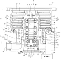
- FIG. 1 is a diagram showing a schematic configuration of a turbo molecular pump 1 according to the first embodiment.
- FIG. 1 shows a cross section of the turbo molecular pump 1 in the axial direction.
- a so-called composite blade type (composite type) vacuum pump including a turbo molecular pump part T and a thread groove type pump part S will be described as an example.
- this Embodiment 1 and this Embodiment 2 are applied to the vacuum pump which has only one of the turbo molecular pump part T or the thread groove pump part S, and the vacuum pump in which the thread groove was provided in the rotary body side. May be.
- the casing 2 forming the outer casing of the turbo molecular pump 1 has a cylindrical shape, and constitutes the outer casing of the turbo molecular pump 1 together with the base 3 provided at the bottom of the casing 2.
- a structure that allows the turbo molecular pump 1 to perform an exhaust function that is, a gas transfer mechanism, is accommodated inside the exterior body of the turbo molecular pump 1.
- the gas transfer mechanism in the turbo molecular pump 1 includes a turbo molecular pump portion T on the intake port 6 side and a thread groove type pump portion S on the exhaust port 19 side. These structures that exhibit the exhaust function are roughly composed of a rotating part that is rotatably supported and a fixed part that is fixed to the casing 2.
- a control device 48 for controlling the operation of the turbo molecular pump 1 is connected to the outside of the exterior body of the turbo molecular pump 1 through a dedicated line.
- the rotating part is composed of a shaft 11 and a rotor part 24 that are rotated by a motor part 10 to be described later.
- the shaft 11 is a rotating shaft (rotor shaft) of the cylindrical member.
- a rotor portion 24 is attached to the upper end of the shaft 11 by a plurality of bolts 25.
- the rotor portion 24 is a rotating member disposed on the shaft 11.
- the rotor part 24 is composed of a rotor blade 21 provided on the intake port 6 side (turbo molecular pump part T) and a cylindrical member 29 provided on the exhaust port 19 side (screw groove type pump part S). .
- the rotor blades 21 are composed of a plurality of blades extending radially from the rotor portion 24 while being inclined at a predetermined angle from a plane perpendicular to the axis of the shaft 11.
- the turbo molecular pump 1 is provided with a plurality of rotor blades 21 in the axial direction.
- the rotor portion 24 is made of a metal such as stainless steel or aluminum alloy.
- the cylindrical member 29 is composed of a member whose outer peripheral surface has a cylindrical shape.
- a motor unit 10 that rotates the shaft 11 is disposed in the middle of the shaft 11 in the axial direction.
- the motor unit 10 is configured by a DC brushless motor.
- a permanent magnet 10 a is fixed to a portion of the shaft 11 constituting the motor unit 10.
- the permanent magnet 10 a is fixed so that the N pole and the S pole are arranged around the shaft 11 every 180 °.
- Around the permanent magnet 10a for example, six electromagnets 10b are arranged symmetrically with respect to the axis of the shaft 11 every 60 ° through a predetermined gap (gap) from the shaft 11. Yes.
- the permanent magnet 10 a functions as a rotor part (rotating part) of the motor unit 10
- the electromagnet 10 b functions as a stator part (fixed part) of the motor unit 10.
- the turbo molecular pump 1 includes a sensor that detects the rotation speed and rotation angle (phase) of the shaft 11, and the control device 48 detects the position of the magnetic pole of the permanent magnet 10 a fixed to the shaft 11 by this sensor. Be able to.
- the control device 48 sequentially switches the current of the electromagnet 10b of the motor unit 10 according to the detected magnetic pole position, and generates a rotating magnetic field around the permanent magnet 10a of the shaft 11.
- the permanent magnet 10a fixed to the shaft 11 follows this rotating magnetic field, whereby the shaft 11 is configured to rotate.
- a radial magnetic bearing unit 8 and a radial magnetic bearing unit 12 that support the shaft 11 in the radial direction, that is, support the load of the rotating unit in the radial direction.
- a thrust magnetic bearing portion 20 that supports the shaft 11 in the axial direction (thrust direction), that is, supports the load of the rotating portion in the thrust direction, is provided at the lower end of the shaft 11.
- the shaft 11 (rotating portion) is supported by the radial magnetic bearing portions 8 and 12 in a non-contact manner in the radial direction (the radial direction of the shaft 11), and is not contacted by the thrust magnetic bearing portion 20 in the thrust direction (the axial direction of the shaft 11). It is supported by.
- These magnetic bearings constitute a so-called five-axis control type magnetic bearing, and the shaft 11 has only a degree of freedom of rotation around the axis.
- electromagnets 8 b are arranged on the radial magnetic bearing portion 8 so as to face the periphery of the shaft 11 every 90 °. These electromagnets 8b are arranged between the shaft 11 via a gap (air gap).
- This gap value is a value that takes into consideration the vibration amount (swing amount) of the shaft 11 in a steady state, the spatial distance between the rotor portion 24 and the stator portion (fixed portion), the performance of the radial magnetic bearing portion 8, and the like.
- a target 8a is formed on the shaft 11 facing the electromagnet 8b.
- the shaft 11 When the target 8a is attracted by the magnetic force of the electromagnet 8b of the radial magnetic bearing portion 8, the shaft 11 is supported in a non-contact manner in the radial direction.
- the target 8 a functions as a rotor portion of the radial magnetic bearing portion 8
- the electromagnet 8 b functions as a stator portion of the radial magnetic bearing portion 8.
- the radial magnetic bearing portion 12 has the same configuration as that of the radial magnetic bearing portion 8, and more specifically, the target 12a is attracted by the magnetic force of the electromagnet 12b of the radial magnetic bearing portion 12, thereby causing the shaft 11 to move in the radial direction. It comes to be supported by contact.
- the thrust magnetic bearing portion 20 floats the shaft 11 in the axial direction via a disk-shaped metal armature disk 30 provided perpendicular to the shaft 11.
- two electromagnets 20 a and 20 b are arranged on the thrust magnetic bearing portion 20 so as to face each other with the armature disk 30 therebetween.
- These electromagnets 20 a and 20 b are arranged with a gap between them and the armature disk 30.
- This gap value is a value that takes into account the amount of vibration of the shaft 11 in a steady state, the spatial distance between the rotor portion 24 and the stator portion, the performance of the thrust magnetic bearing portion 20, and the like.
- the armature disk 30 is attracted by the magnetic force of the electromagnets 20a and 20b of the thrust magnetic bearing portion 20, so that the shaft 11 is supported in a non-contact manner in the thrust direction (axial direction).
- Displacement sensors 9 and 13 are formed in the vicinity of the radial magnetic bearing portions 8 and 12, respectively, so that the displacement of the shaft 11 in the radial direction can be detected. Further, a displacement sensor 17 is formed at the lower end of the shaft 11 so that the displacement of the shaft 11 in the axial direction can be detected.
- the displacement sensors 9 and 13 are elements that detect the displacement of the shaft 11 in the radial direction. In this embodiment, the displacement sensors 9 and 13 are constituted by inductance type sensors such as eddy current sensors provided with the coils 9b and 13b.
- the coils 9 b and 13 b in the displacement sensors 9 and 13 are part of an oscillation circuit formed in the control device 48 installed outside the turbo molecular pump 1.
- the displacement sensor 9 generates a high-frequency magnetic field on the shaft 11 as a high-frequency current flows with the oscillation of the oscillation circuit.
- the oscillation amplitude of the oscillation circuit changes, whereby the displacement of the shaft 11 can be detected.
- the sensor for detecting the displacement of the shaft 11 is not limited to this, and for example, a capacitance type or an optical type may be used.
- the control device 48 detects the radial displacement of the shaft 11 based on the signals from the displacement sensors 9 and 13, the control device 48 adjusts the magnetic force of the electromagnets 8 b and 12 b of the radial magnetic bearing portions 8 and 12 to place the shaft 11 in a predetermined position. Operate to return. As described above, the control device 48 feedback-controls the radial magnetic bearing portions 8 and 12 based on the signals of the displacement sensors 9 and 13. As a result, the shaft 11 is magnetically levitated in the radial direction with a predetermined gap (gap) from the electromagnets 8b and 12b in the radial magnetic bearing portions 8 and 12, and is held in a non-contact manner in the space.
- a predetermined gap gap
- the displacement sensor 17 is also provided with a coil 17 b.
- the displacement in the thrust direction is detected by detecting the distance from the target 17a provided on the shaft 11 side facing the coil 17b.
- the control device 48 detects the displacement of the shaft 11 in the thrust direction based on the signal from the displacement sensor 17, the control device 48 adjusts the magnetic force of each of the electromagnets 20 a and 20 b of the thrust magnetic bearing unit 20 to return the shaft 11 to a predetermined position. To work. As described above, the control device 48 feedback-controls the thrust magnetic bearing unit 20 based on the signal from the displacement sensor 17.
- the shaft 11 is magnetically levitated in the thrust direction in the thrust magnetic bearing portion 20 from the electromagnets 20a and 20b with a predetermined gap, and is held in the space without contact.
- the shaft 11 is held in the radial direction by the radial magnetic bearing portions 8 and 12 and is held in the thrust direction by the thrust magnetic bearing portion 20, so that the shaft 11 rotates around the axis.
- the stator portion includes a stator blade 22 provided on the intake port 6 side (turbo molecular pump portion T), a thread groove spacer 5 provided on the exhaust port 19 side (screw groove type pump portion S), a stator column 18 and the like. It is composed of The stator blade 22 is composed of a blade that is inclined from the plane perpendicular to the axis of the shaft 11 by a predetermined angle and extends from the inner peripheral surface of the casing 2 toward the shaft 11. In the turbo molecular pump portion T, the stator blades 22 are formed in a plurality of stages alternately with the rotor blades 21 in the axial direction. The stator blades 22 at each stage are separated from each other by a cylindrical spacer 23.
- the thread groove spacer 5 is a cylindrical member in which the spiral groove 7 is formed on the inner peripheral surface and the thickness on the exhaust port 19 side (near the base 3) is thin.
- a gap 90 is provided between the outer peripheral surface of the portion where the thickness of the thread groove spacer 5 is thin and the base 3 (or the casing 2).
- the vibration sensor 100 is provided on the outer peripheral surface in the site
- the vibration sensor 100 is a sensor that functions as a contact detection unit that detects contact between the rotating part and the fixed part inside the turbo molecular pump 1, and converts vibration amplitude into an electric signal.
- an acceleration pickup a piezoelectric element, It consists of a moving coil and strain gauge.
- the sensitivity adjustment device sensitivity adjustment function
- the vibration sensor 100 is built in the turbo molecular pump 1. Since there are individual differences in the vibration sensor 100, it is necessary to adjust the conversion rate (conversion sensitivity) when converting the vibration level into an electrical signal. As described above, by providing the sensitivity adjusting device inside the turbo molecular pump 1, even when the combination of the control devices 48 is changed (when connected to another control device 48), the sensitivity of the vibration sensor 100 is improved. This eliminates the need to adjust each time, improving convenience.
- the inner peripheral surface of the thread groove spacer 5 faces the outer peripheral surface of the cylindrical member 29 with a predetermined gap therebetween.
- the direction of the spiral groove 7 formed in the thread groove spacer 5 is the direction toward the exhaust port 19 when the gas is transported in the spiral groove 7 in the rotational direction of the rotor portion 24.
- the depth of the spiral groove 7 becomes shallower as it approaches the exhaust port 19. The gas transported through the spiral groove 7 is compressed as it approaches the exhaust port 19.
- the base 3 constitutes an exterior body of the turbo molecular pump 1 together with the casing 2.
- a stator column 18 having a cylindrical shape concentric with the rotation axis of the rotating portion is attached in the direction of the intake port 6.
- the motor unit 10 and the radial magnetic bearing units 8 and 12 are disposed.
- the turbo molecular pump 1 is provided with a protective bearing 40 on the intake port 6 side of the displacement sensor 9 and a protective bearing 49 on the exhaust port 19 side of the displacement sensor 13.
- the protective bearings 40 and 49 are used in an emergency (at the time of touchdown) in which the radial magnetic bearing portions 8 and 12 and the thrust magnetic bearing portion 20 do not operate normally due to the turbo molecular pump 1 being started, stopped, or powered off. This is a bearing for supporting the shaft 11.
- the turbo molecular pump 1 having such a configuration is used as a vacuum pump when performing exhaust processing of a vacuum chamber, for example, a process chamber provided in a semiconductor manufacturing apparatus in which the inside is maintained in a high vacuum state. .
- the turbo molecular pump 1 sucks and exhausts process gas from the process chamber.
- These process gases are introduced into the chamber at elevated temperatures to increase reactivity.
- a part of these process gases is solidified into a solid product by becoming a pressure higher than a certain pressure in the process of being evacuated in the turbo molecular pump 1 or by being cooled. It adheres and deposits on the surface of one channel.
- the distance between the rotating part and the fixed part in the turbo molecular pump 1, for example, the distance between the rotor blade 21 and the stator blade 22, and the distance between the cylindrical member 29 and the thread groove spacer 5 are extremely narrow. For this reason, if a solid product as described above accumulates a predetermined amount or more in the clearance (gap) between the rotating part and the fixed part, the rotating part and the fixed part come into contact with each other through the solid product. In the turbo molecular pump 1, the rotating part rotates at a high speed of several tens of thousands of rotations per minute. Therefore, when a rotating part and a fixed part contact, there exists a possibility that a deformation
- the vibration sensor is used to detect contact between the rotating part and the fixed part inside the turbo molecular pump.
- the turbo molecular pump 1 (control device 48), when the vibration detected by the vibration sensor 100 satisfies any of the following conditions, contact between the rotating part and the fixed part occurs in the turbo molecular pump 1. Detect. (1) When the vibration level (amplitude magnitude) at the natural frequency of the components (stator blade 22, spacer 23, thread groove spacer 5) constituting the fixed part exceeds a predetermined threshold. (2) The vibration level at the natural frequency of the components (rotor blades 21, cylindrical member 29, shaft 11, rotor portion 24) constituting the rotating body at the rotation speed (frequency) of the rotation section has exceeded a predetermined threshold value. If. (3) The vibration level at a frequency that is a multiple of the number of rotations (frequency) of the rotating part exceeds a predetermined threshold.
- the control device 48 When the vibration sensor 100 detects (detects) the vibration described above, the control device 48 is configured to issue an alarm signal indicating an abnormal state. When this alarm signal is issued, the turbo molecular pump 1 according to the present embodiment automatically stops its operation in order to prevent parts from being damaged. In order to avoid the influence of false detection due to externally applied shock (disturbance) or noise received by the vibration sensor 100, the control device 48 is provided with a timer function, and when an alarm signal is continuously generated for a predetermined time or more, The operation of the turbo molecular pump 1 may be stopped.
- the time interval (detection timing interval) at which the vibration sensor 100 detects (detects) the vibration described above is shortened over time, and a predetermined interval time ( An alarm signal may be issued when the period becomes shorter than the period.
- an alarm signal is generated only when the number of times contact is detected exceeds a predetermined number (threshold), or when the integrated value of the time when contact is detected exceeds a predetermined time (threshold). Also good.
- the timing which issues an alarm signal is not limited to the conditions mentioned above.
- the alarm signal is divided into a plurality of times (for example, two stages) to notify in advance that the maintenance time is approaching, and the turbo molecular pump 1 does not suddenly become unusable. You may do it. Specifically, after issuing an alarm signal notifying that it is the initial stage of contact between the rotating part and the fixed part, the contact state advances and the turbo molecular pump 1 is automatically stopped (or urged to stop). Send an alarm signal to inform you.
- timing for issuing such an alarm signal indicating the level difference in the degree of contact is arbitrarily set based on, for example, the number of times contact is detected, the integrated value of the time at which contact is detected, the fluctuation value of the contact detection interval, etc. can do.
- the following intermittent contact phenomenon occurs until the contact is always brought into contact.
- Contact due to solid product ⁇ Wear of contact portion ⁇ Temporary non-contact state ⁇ Deposition of solid product and progress of deformation of rotating portion (for example, expansion of cylindrical member 29) ⁇ Normal contact.
- an alarm signal corresponding to the contact level may be issued while monitoring the contact cycle interval, that is, the timing at which the contact detection interval becomes transiently short.
- the vibration sensor 100 detects (detects) the specific vibration generated when the rotating unit and the fixed unit are in contact with each other, the alarm signal is generated, and the turbo is generated at an appropriate time (timing).
- the operation of the molecular pump 1 can be stopped. Thereby, the damage (breakage) of the components of the turbo molecular pump 1 can be prevented in advance, and the running cost of the turbo molecular pump 1 can be reduced and the safety can be improved.
- the determination conditions shown in the above (1) to (5) capture not only the vibration amplitude but also the specific vibration generated when the rotating part and the fixed part are in contact with each other. This is for the purpose of differentiation (discrimination).
- vibration is excited in the rotating part and the fixed part due to the impact.
- the presence / absence of contact between the rotating portion and the fixed portion is determined based on this excitation vibration component.
- the conditions shown in the above (1) and (2) use the property (characteristic) that the amplitude at the natural frequency at which the damping of each component is minimized in the vibration excited to each component by contact. Is set. Note that, even when excitation is caused by external vibration, vibration at the natural frequency of the component is generated. However, when the component is directly excited by contact, this vibration level increases. Therefore, when this vibration level greatly exceeds a predetermined threshold value, it can be determined that contact has occurred.
- the natural frequency of the component shown by the said conditions includes what originates (causes) by the rigidity of the local of the component integrally formed, the whole, and an attachment part.
- the natural frequency of a part changes due to a change in the part dimension due to a mechanical tolerance of the part, temperature, or a change in rigidity of the mounting portion. Therefore, when detecting vibration at a natural frequency of a certain part, a peak value of vibration existing in a frequency range having a certain degree of clearance (margin width) is captured. Therefore, in the present embodiment, a signal converted into an electric signal by a detection unit such as the vibration sensor 100 is extracted using a bandpass filter that passes an assumed frequency band, and the size of the extracted signal is determined. The presence or absence of contact between the rotating part and the fixed part is determined by comparing with a predetermined threshold value.
- the vibration at the natural frequency of the components constituting the rotating body exists even when the rotating part and the fixed part are not in contact with each other.
- the vibration is transmitted to the fixed part side via the shaft 11 and the like. Communicated. Therefore, the predetermined threshold value under the condition shown in (2) above is set to a value that can appropriately exclude the vibration level at the natural frequency of the components constituting the rotating body transmitted to the fixed part side in such a normal state.
- the natural frequency of the parts constituting the rotating body varies depending on the number of rotations due to the acting centrifugal force and gyro moment. Therefore, in the present embodiment, the characteristics (passband characteristics) of the bandpass filter described above are changed in advance according to the number of rotations of the rotating unit.
- control device 48 is pre-recorded with map information for changing the filter characteristics in accordance with the rotational speed, and is configured to change the setting of the filter to be used based on this map information.
- map information for changing the filter characteristics in accordance with the rotational speed
- the conditions shown in (3) above are set based on the following reasons.
- (A) The frequency of the main excitation force of the vibration excited by the contact between the rotating part and the fixed part is caused by the rotational frequency, and the multiple times of the vibration is excited by the parts on the fixed part side.
- the predetermined threshold value under the condition (3) is set to a value that can appropriately exclude the vibration level transmitted to the fixed portion side in such a normal state.
- FIG. 2A is a diagram illustrating a configuration example of another detection unit.
- a vibration sensor 101 is further provided on the outer peripheral surface of the base 3, and vibration detection is performed using the two sensors of the vibration sensor 100 and the vibration sensor 101.
- the vibration sensor 100 is disposed on the thread groove spacer 5
- the vibration sensor 101 is disposed on the base 3 to which the thread groove spacer 5 is fixed.
- the vibration sensor 101 is disposed on another component (base 3) stacked on the component (screw groove spacer 5) on which the vibration sensor 100 is disposed. That is, the vibration sensors 100 and 101 are not disposed on the same component constituting the fixed portion, but are disposed on components having different numbers of stacked components.
- the vibration sensor 101 provided on the outer peripheral surface of the turbo molecular pump 1 (base 3) can more significantly detect vibration caused by an externally applied impact (disturbance). it can.
- the difference of each detection result (output signal) with the sensor 101 is calculated.
- the control device 48 determines whether or not the contact between the fixed portion and the rotating portion has occurred based on the calculated difference signal.
- a vibration sensor 101 is further provided on a part physically separated from the contact portion, and the vibration sensor 101 and the vibration sensor 100 are obtained. Based on the difference between the signals (difference signal), vibration due to contact is captured preferentially.
- the vibration sensor 101 that detects the comparison signal for calculating the difference signal with respect to the vibration sensor 100 is disposed on the base 3 stacked on the thread groove spacer 5 has been described.
- the portion where the vibration sensor 101 is disposed is not limited to this, and may be provided in another fixing portion (for example, the casing 2) stacked on the thread groove spacer 5.
- FIG. 2B is a view showing another arrangement example of the vibration sensor 100.
- the vibration sensor 50 may be disposed on the fixed portion via a plate-like beam 60 attached to the thread groove spacer 5.
- a beam 60 having an L-shaped cross section is formed on the step formed on the exhaust port 19 side of the thread groove spacer 5 so that the L-shaped vertical bar is parallel to the outer peripheral wall of the thread groove spacer 5.
- the vibration sensor 100 may be disposed on the side surface of the L-shaped vertical bar portion of the beam 60.
- the beam 60 is configured such that its own natural frequency becomes the frequency of the excitation vibration that is the determination condition shown in the above (1) to (5), or a frequency in the vicinity of a multiple of this excitation vibration. .
- the vibration sensor 100 is disposed via the beam 60 in order to expand (amplify) and capture the vibration excited in the portion on the fixed portion side.
- the vibration (amplitude) generated in the turbo molecular pump 1 can be easily amplified, vibration detection accuracy can be improved.
- the vibration sensor 100 By arranging the vibration sensor 100 via the beam 60, the vibration frequency to be extracted can be appropriately narrowed down, so that the vibration detection accuracy can be further improved.
- the vibration level at the natural frequency of the beam 60 in the vibration detected by the vibration sensor 100 appears significantly large. Therefore, as a component constituting the fixed part, it is possible to sufficiently determine whether or not there is contact between the rotating part and the fixed part simply by monitoring (managing) the vibration level (magnitude) of the beam 60 at the natural frequency. can do.
- the vibration sensor 100 is provided with a fixing portion (thread groove spacer 5 ′) where the vibration sensor 100 is disposed. It may be fixed to the exterior body (casing 2, base 3) via a vibration buffer member (elastomer) having a vibration damping rate higher (larger) than that of the fixing member provided with.
- FIG. 2C is a diagram illustrating an arrangement example using a vibration damping member. Specifically, as shown in FIG. 2C, an elastic member 70 is disposed between the outer peripheral side surface of the thread groove spacer 5 ′ and the inner peripheral side surface of the base 3.
- an elastic member 71 is disposed between a flange-like attachment portion 55 to the base 3 provided on the inlet 6 side of the thread groove spacer 5 ′ and the attachment surface of the base 3. Further, the washer 72 of the bolt 80 for fixing (fastening) the mounting portion 50 of the thread groove spacer 5 'and the base 3 is formed of an elastic body.
- the vibration absorbing (vibration damping) member is preferably composed of a resin member such as rubber or plastic. Such a structure using the vibration damping member (elastic member / elastic body) may be applied not only to the third modification of the first embodiment but also to each of the modifications described above.
- the rotation part and the fixed part are easy to contact the vibration sensor 100 for detecting the specific vibration generated at the time of contact between the rotary part and the fixed part.
- the case where the solid product is attached to a portion close to the downstream side (exhaust port 19 side) of the gas transfer path where the solid product easily deposits has been described.
- the attachment site of the vibration sensor 100 is not limited to this, and the vibration sensor 100 may be provided on another fixed portion that faces the rotating portion, for example, the stator blade 22 or the spacer 23.
- a vibration buffer member may be provided between the exterior body and the exterior body.
- First Embodiment Modification 4 In the first embodiment and each of the first to third modifications, the case where the vibration sensor 100 disposed on the fixed portion side is used as a method for detecting contact between the rotating portion and the fixed portion inside the turbo molecular pump 1 has been described. .
- a method for detecting a specific vibration generated when the rotating unit and the fixed unit are in contact with each other is not limited to these methods.
- the presence or absence of contact between the rotating part and the fixed part may be detected by detecting the vibration of the rotating part, that is, the time change of the displacement of the rotating part.
- a sensor for monitoring the displacement of a rotating part such as the shaft 11 and the rotor part 24 (the rotor blade 21 and the cylindrical member 29) is provided, and based on the detection result (detection result) of this sensor. The presence or absence of contact between the rotating part and the fixed part is determined.
- This sensor is composed of, for example, an inductance type, eddy current type, electrostatic capacity type, or optical non-contact displacement sensor that converts the vibration amplitude of the rotating part into an electric signal.
- a sensor (non-contact sensor) for detecting the contact between the rotating part and the fixed part may also be used as the displacement sensors 9 and 13 used when controlling the radial magnetic bearing parts 8 and 12. . Then, based on the monitoring result of the displacement of the rotating part, it is determined whether or not the vibration of the rotating part satisfies any of the determination conditions (1) to (5) described above.
- the presence or absence of contact between the rotating part and the fixed part can also be determined by directly monitoring the vibration of the rotating part.
- a phenomenon that satisfies the above conditions occurs a plurality of times within a predetermined time, or occurs continuously for a predetermined time. For example, it may be detected that contact between the rotating portion and the fixed portion has occurred.
- a beam member similar to the beam 60 described above may be fixed to the rotating portion, and the displacement (vibration) of the beam member may be detected.
- the vibration (amplitude) generated in the turbo molecular pump 1 can be easily amplified, so that the vibration detection accuracy can be improved.
- the sensitivity adjusting device 103 is provided on the inner peripheral surface of the substantially cylindrical base 3.
- the arrangement position of the sensitivity adjusting device 103 is not limited to this.
- the vibration sensor There is no need to adjust the sensitivity of 102 each time. Therefore, it is not necessary to accompany a measuring instrument for sensitivity adjustment at the time of exchanging the turbo molecular pump 1 ', the simplification of the exchanging operation can be achieved, and convenience is improved.
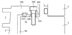
- FIG. 4 is an enlarged view of a broken line
- FIG. 5 is a plan view of a state in which the thread groove spacer 5 is attached to the base 3 as viewed from the intake port 6 side.
- the thread groove spacer 5 is attached to the base 3 with a plurality of bolts 300 via an O-ring 200.
- the thread groove spacer 5 has an annular ring for fixing projecting outward at the end of the cylindrical portion in which the spiral groove 7 is formed on the inner peripheral surface.
- a flange portion 106 is provided.
- An annular attachment portion 107 having a thickness smaller than that of the flange portion 106 is provided on the outer peripheral edge of the flange portion 106.
- bolt holes 108 through which the fixing bolts 300 are inserted are formed in the mounting portion 107 at four locations on the circumference equally.
- claw portions 109 for positioning the thread groove spacer 5 that protrude in the direction of the casing 2 from the outer peripheral edge are formed in the mounting portion 107 at four locations equally divided in the circumference.
- the claw portion 109 is formed so that the contact area with the exterior body is sufficiently small in order to suppress the influence of external vibration propagating from the exterior body (casing 2, base 3) to the thread groove spacer 5.
- the thread groove spacer 5 is formed with a ring groove 110 along the circumferential direction for fitting and fixing the O-ring 200 on the surface of the flange portion 106 on the exhaust port 19 side.
- the flange portion 106 is fixed to the end surface of the base 3 on the intake port 6 side by the bolt 300.
- the bolt 300 is directly attached to the thread groove spacer 5 (mounting) in order to suppress the influence of the external vibration propagating from the exterior body (casing 2, base 3) to the thread groove spacer 5 via the bolt 300.
- a cylindrical bush (bushing) 301 is disposed in the bolt hole 108 so as not to contact the portion 107). That is, the thread groove spacer 5 is attached to the base 3 with the bolt 300 inserted through the bush 301.
- the O-ring 200 is made of an elastic member having vibration damping characteristics, for example, a fluorine resin, which is sufficient to prevent the thread groove spacer 5 and the base 3 from contacting when the thread groove spacer 5 is fixed to the base 3.
- a shape having a large cross-sectional diameter is used.
- the O-ring 200 is preferably formed of a material classified into “4 types D” in the JIS standard.
- the bush 301 is also formed of an elastic member having vibration damping characteristics, such as nylon.
- FIGS. 6A and 6B are views showing a modification of the method for attaching the thread groove spacer 5 in the second embodiment.
- FIG. 6 the same parts as those in FIGS. 1 and 4 are denoted by the same reference numerals, and detailed description thereof is omitted.
- Embodiment 2 Modification 1 For example, as shown in FIG. 6A, a ring groove 201 for fitting and fixing the O-ring 200 is formed not on the thread groove spacer 5 but on the end face on the inlet 6 side of the base 3 along the circumferential direction. You may make it do. Further, ring grooves 110 (FIG. 4) and 201 (FIG.
- the O-ring 200 may be provided on both the end face of the base 3 on the intake port 6 side and the thread groove spacer 5.
- the O-ring 200 has a shape having a sufficient cross-sectional diameter so that the thread groove spacer 5 and the base 3 do not contact when the thread groove spacer 5 is fixed to the base 3.
- an annular plate-like shape having vibration damping characteristics is used instead of the O-ring 200 between the thread groove spacer 5 and the end face on the intake port 6 side of the base 3.
- the elastic body 202 may be provided.
- an annular plate-like elastic body 202 in which bolt holes 203 for inserting the bolts 300 and the bushings 301 are formed at positions corresponding to the four bolt holes 108 equally divided in the circumferential direction is connected to the intake port of the base 3.
- the thread groove spacer 5 may be fixed in a state of being sandwiched between the end surface on the 6 side and the surface on the exhaust port 19 side of the mounting portion 107.
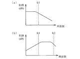
- FIG. 7A is a graph showing the vibration propagation characteristics of the elastic member.
- the elastic member has frequency characteristics of a low-pass filter whose cutoff frequency (cutoff frequency) is fc1 [Hz]. That is, the elastic member propagates to the thread groove spacer 5 side without attenuating vibration (hereinafter referred to as external vibration) caused by an impact (disturbance) applied to the exterior body having a frequency smaller than fc1 [Hz].
- the external vibration having a frequency of fc1 [Hz] or more is attenuated by 20 dB / decad and is difficult to propagate to the thread groove spacer 5 side.
- the cut-off frequency of the elastic member described above indicates a value set based on the rigidity of the state of being disposed between the thread groove spacer 5 and the exterior body.
- the control device 48 is provided with an A / D conversion circuit (not shown) that converts an analog vibration signal output from the vibration sensor 102 into a digital vibration signal. Further, the control device 48 is further provided with a supervisor circuit (not shown) based on a DSP that receives a digitized vibration signal from the A / D conversion circuit. This supervisor circuit is programmed to detect contact between the rotating part and the fixed part in the turbo molecular pump 1 '.
- a digital filter is incorporated in the supervisor circuit, and a vibration signal having a predetermined passband frequency is extracted by inputting the digital vibration signal to the digital filter.
- the supervisor circuit detects that the contact between the fixed portion and the rotating portion has occurred in the turbo molecular pump 1 ′. Is programmed.
- FIG. 7B is a graph showing the attenuation characteristics of the vibration signal of the digital filter in the supervisor circuit.
- the digital filter has a frequency characteristic of a bandpass filter whose passband is the fc1 to fc2 [Hz] band.
- the digital filter has a characteristic of attenuating and outputting a vibration signal having a frequency smaller than fc1 [Hz] and a vibration signal having a frequency larger than fc2 [Hz] among the input vibration signals. That is, it has a characteristic of outputting only a vibration signal of fc1 [Hz] or more and fc2 [Hz] or less.
- fc1 [Hz] indicating the lower limit of the pass band of the digital filter is an elastic member (O-ring) disposed between the above-described thread groove spacer 5 and the exterior body (casing 2, base 3). 200, the elastic body 202) is set to coincide with the cutoff frequency.
- the cut-off frequency (fc1) of the elastic member is set to about 100 [Hz] in consideration of the band of resonance vibration that occurs during acceleration / deceleration of the turbo molecular pump 1 ′.
- the second embodiment is configured to determine the presence or absence of contact between the fixed portion and the rotating portion by comparing the vibration signal that has passed through the digital filter with a predetermined threshold value.
- the vibration signal due to the action of the elastic member disposed between the thread groove spacer 5 and the exterior body, the vibration signal in a band not containing (small) the component of external vibration, that is, the influence of external vibration. It is configured to determine whether or not there is a contact between the fixed portion and the rotating portion based on a vibration signal in a band that is not (or is not easily received).
- the presence or absence of contact between the fixed portion and the rotating portion is determined based on the vibration signal in the band where the impact or vibration component due to the contact between the fixed portion and the rotating portion remains (extracted). It is configured. Accordingly, since erroneous detection due to the influence of external vibration can be suppressed, it is possible to determine the presence or absence of contact between the fixed portion and the rotating portion with higher accuracy.
- the presence or absence of contact between the fixed portion and the rotating portion with the simple configuration as described above that is, detecting that the amount of solid product deposited has reached the clearance between the rotating portion and the fixed portion. Can do.
- a bandpass filter is used as a method for extracting a band in which an impact or vibration component due to contact between the fixed part and the rotating part remains (extracted), but instead of the bandpass filter.
- a high-pass filter having a cutoff frequency (cut-off frequency) of fc1 [Hz] that can eliminate at least external vibration or a component of resonance vibration generated during acceleration / deceleration of the turbo molecular pump 1 ′ may be used.
- the control device 48 When the control device 48 (supervisor circuit) detects (detects) the contact between the fixed portion and the rotating portion of the turbo molecular pump 1 ′, the control device 48 is configured to issue an alarm signal indicating an abnormal state. Yes. When this alarm signal is issued, the turbo molecular pump 1 ′ according to the second embodiment automatically stops its operation in order to prevent the parts from being damaged. In order to avoid the influence of false detection due to externally applied impact (disturbance) or noise received by the vibration sensor 102, a timer function is provided in the control device 48, and when an alarm signal is continuously generated for a predetermined time or more, The operation of the turbo molecular pump 1 ′ may be stopped.
- the time interval (detection timing interval) at which the vibration sensor 102 detects (detects) the vibration described above is shortened over time, and a predetermined interval time ( An alarm signal may be issued when the period becomes shorter than the period.
- an alarm signal is generated only when the number of times contact is detected exceeds a predetermined number (threshold), or when the integrated value of the time when contact is detected exceeds a predetermined time (threshold). Also good.
- the timing which issues an alarm signal is not limited to the conditions mentioned above.
- the alarm signal is divided into multiple times (for example, two stages) to notify in advance that the maintenance time is approaching, and the turbo molecular pump 1 'suddenly becomes unusable. It may not be possible.
- the contact state proceeds and the turbo molecular pump 1 ′ is automatically stopped (or stopped).
- Prompt Issue an alarm signal to inform you that the situation is present.
- timing for issuing such an alarm signal indicating the level difference in the degree of contact is arbitrarily set based on, for example, the number of times contact is detected, the integrated value of the time at which contact is detected, the fluctuation value of the contact detection interval, etc. can do.
- the following intermittent contact phenomenon occurs until the contact is always brought into contact.
- Contact due to solid product ⁇ Wear of contact portion ⁇ Temporary non-contact state ⁇ Deposition of solid product and progress of deformation of rotating portion (for example, expansion of cylindrical member 29) ⁇ Normal contact.
- an alarm signal corresponding to the contact level may be issued while monitoring the contact cycle interval, that is, the timing at which the contact detection interval becomes transiently short.
- the vibration sensor 102 detects (detects) the specific vibration that occurs when the rotating unit and the fixed unit are in contact with each other as described above, an appropriate timing (timing) is generated by issuing an alarm signal or a contact notification signal.
- an appropriate timing is generated by issuing an alarm signal or a contact notification signal.
- the sensitivity adjusting device 103 of the vibration sensor 102 is built in the main body side of the turbo molecular pump 1 ′ so that it is not necessary to adjust the sensitivity of the vibration sensor 102 each time.
- the method of eliminating the need to adjust the sensitivity of the vibration sensor 102 each time is not limited to this.
- an adjustment value of the detection signal level of the vibration sensor 102 set at the time of factory shipment is incorporated on the main body side of the turbo molecular pump 1 ′.
- the control device 48 may read out and adjust the adjustment value of the detection signal level of the vibration sensor 102 from the storage device.
- the adjustment value of the detection signal level of the vibration sensor 102 is preferably stored in a memory mounted on the pump internal substrate 104, for example.
- the adjustment value of the detection signal level of the vibration sensor 102 is stored in the storage device built in the main body side of the turbo molecular pump 1 ′, so that, for example, even when the control device 48 is replaced, the vibration There is no need to adjust the detection signal level of the sensor 102 each time, and convenience is improved.
- the output signal of the vibration sensor 102 is converted into a digital signal, but the processing method of the output signal of the vibration sensor 102 is not limited to this.
- a process for detecting contact between the rotating part and the fixed part may be performed without converting the digital signal into an analog signal.
- an analog filter having similar characteristics is used instead of the digital filter described above.
- the vibration sensor 102 for detecting a specific vibration generated when the rotating portion and the fixed portion are in contact with each other is used.
- the case where it is attached to a portion close to the downstream side (exhaust port 19 side) of the gas transfer path that is easy to contact, that is, where the solid product is easily deposited has been described.
- the attachment site of the vibration sensor 102 is not limited to this, and the vibration sensor 102 may be provided on another fixed portion that faces the rotating portion, for example, the stator blade 22 or the spacer 23.
- an elastic member is disposed between the fixed portion where the vibration sensor 102 is provided and the exterior body.
Landscapes
- Engineering & Computer Science (AREA)
- Mechanical Engineering (AREA)
- General Engineering & Computer Science (AREA)
- Non-Positive Displacement Air Blowers (AREA)
- Structures Of Non-Positive Displacement Pumps (AREA)
- Control Of Positive-Displacement Air Blowers (AREA)
Abstract
Description
このような回転部と固定部が接触した状態を、メンテナンス(オーバーホール)を行わずに放置しておくと、重大な不具合が生じるおそれがある。
特許文献2には、静電容量型膜圧センサを用いて、固体生成物(異物)の堆積量を直接測定する技術が提案されている。
特許文献3には、ガス流路の温度と、ガス流路でない部分の温度との温度差を測定し、この温度差に基づいてガス流路に堆積した固体生成物の量を計測する技術が提案されている。
また、ポンプが接続される真空バルブの開閉等に伴う機械的振動や、ポンプやポンプが接続される装置(真空容器等)に加えられた外部振動に起因する振動振幅の増加を、回転部と固定部との物理的な接触に起因する振動振幅の増加と区別することができなかった。
そこで本発明は、真空ポンプにおいて、回転部と固定部との物理的な接触を精度よく検出することを第1の目的とする。
そこで本発明は、固体生成物の堆積量が、回転部と固定部とのクリアランスに達したことをより精度良く検知することを第2の目的とする。
請求項2に記載の発明では、前記特定振動は、前記固定部を構成する部品の固有振動数を示す第1の周波数、前記回転部を構成する部品の固有振動数を示す第2の周波数、前記回転部の回転数(周波数)の逓数倍の周波数を示す第3の周波数、前記第1から第3の周波数での振動のうなり周波数を示す第4の周波数、前記回転部と前記固定部とが接触する際に発生する特定範囲の第5の周波数のうちの少なくとも1の周波数の振動であることを特徴とする請求項1に記載の真空ポンプを提供する。
請求項3に記載の発明では、前記振動検出手段は、前記固定部における前記回転部と対向する部材に配設された振動センサからなることを特徴とする請求項1又は請求項2に記載の真空ポンプを提供する。
請求項4に記載の発明では、前記振動検出手段は、前記固定部の異なる部位に設けられた複数の振動センサで構成され、前記振動センサにより検出された振動の差分に基づいて、前記固定部と前記回転部との接触が発生したことを検知することを特徴とする請求項1から請求項3のいずれか1の請求項に記載の真空ポンプを提供する。
請求項5に記載の発明では、前記振動検出手段が設けられた固定部は、弾性部材を介して前記外装体に固定されていることを特徴とする請求項1から請求項4の何れか1の請求項に記載の真空ポンプを提供する。
請求項6に記載の発明では、前記振動検出手段は、前記回転部の位置変位の時間的変化を振動として検出することを特徴とする請求項1又は請求項2に記載の真空ポンプを提供する。
請求項7に記載の発明では、前記振動検出手段は、前記回転部の変位を検出する非接触変位センサからなることを特徴とする請求項6に記載の真空ポンプを提供する。
請求項8に記載の発明では、前記接触検知手段により、前記固定部と前記回転部との接触が発生したことを検知した場合、メンテナンスの実施を促すアラームを発するアラーム出力手段を備えたことを特徴とする請求項1から請求項7の何れか1の請求項に記載の真空ポンプを提供する。
また、本発明は、前記第2の目的を達成するために、請求項9に記載の発明では、吸気口と排気口を備えた外装体と、前記外装体内に設けられた固定部と、前記外装体内に回転自在に支持されたシャフトと、前記シャフトに配設され、前記吸気口から前記排気口へ気体を移送する気体移送機構が設けられたロータと、からなり、前記固定部との間に所定の空隙を介して配置された回転部と、前記シャフトを回転させるモータと、前記外装体と前記固定部との間に配設された、振動減衰特性を有する弾性部材と、前記固定部に配設された振動検出手段と、前記振動検出手段の出力が入力され、前記弾性部材の振動減衰特性における遮断周波数より高い周波数帯域を通過帯域とするフィルタと、前記フィルタの出力が所定の閾値を超えた場合、前記固定部と前記回転部との接触が発生したことを検知する接触検知手段と、を備えたことを特徴とする真空ポンプを提供する。
請求項10に記載の発明では、ターボ分子ポンプ部及びねじ溝ポンプ部を備えた複合型真空ポンプであって、前記振動検出手段は、前記ねじ溝ポンプ部の排気流路を形成するねじ溝スペーサに配設されていることを特徴とする請求項9に記載の真空ポンプを提供する。
請求項11に記載の発明では、前記外装体又はその内部に設けられた、前記振動検出手段の感度調整を行う感度調整手段を備えたことを特徴とする請求項9又は請求項10に記載の真空ポンプを提供する。
請求項12に記載の発明では、前記外装体又はその内部に設けられた、前記振動検出手段における出力レベルの補正値を記憶する記憶手段を備えたことを特徴とする請求項9又は請求項10に記載の真空ポンプを提供する。
請求項13に記載の発明では、前記弾性部材は、Oリング材料で形成されるか、又は、円周方向に連続するOリングからなることを特徴とする請求項9から請求項12の何れか1の請求項に記載の真空ポンプを提供する。
請求項14に記載の発明では、前記振動検出手段は、振動検出値を変換したデジタル信号を出力し、前記フィルタは、デジタルフィルタで構成されていることを特徴とする請求項9から請求項13の何れか1の請求項に記載の真空ポンプを提供する。
請求項15に記載の発明では、前記接触検知手段により、前記固定部と前記回転部との接触が発生したことを検知した場合、メンテナンスの実施を促すアラーム、又は、接触通知信号を発するアラーム出力手段を備えたことを特徴とする請求項9から請求項14の何れか1の請求項に記載の真空ポンプを提供する。
1′本実施形態2に係わる、ターボ分子ポンプ
2 ケーシング
3 ベース
5 ねじ溝スペーサ
6 吸気口
7 らせん溝
8 ラジアル磁気軸受部
9 変位センサ
10 モータ部
11 シャフト
12 ラジアル磁気軸受部
13 変位センサ
17 変位センサ
18 ステータコラム
19 排気口
20 スラスト磁気軸受部
21 ロータ翼
22 ステータ翼
23 スペーサ
24 ロータ部
25 ボルト
29 円筒部材
30 アーマチュアディスク
40 保護用ベアリング
48 制御装置
49 保護用ベアリング
50 取付部
60 梁
70、71 弾性部材
72 座金
80 ボルト
90 空隙
100、101、102 振動センサ
103 感度調整装置
104 ポンプ内部基板
105 裏蓋
106 フランジ部
107 取付部
108 ボルト孔
109 爪部
110 リング溝
200 Oリング
201 リング溝
202 弾性体
203 ボルト孔
300 ボルト
301 ブッシュ(ブッシング)
(1)実施形態の概要
本実施形態1及び本実施形態2では、回転部と固定部との接触検知機能を有する真空ポンプの一例として、ターボ分子ポンプを用いて説明する。
図1は、本実施形態1に係るターボ分子ポンプ1の概略構成を示した図である。なお、図1は、ターボ分子ポンプ1の軸線方向の断面を示している。
本実施形態1では、ターボ分子ポンプ1の一例としてターボ分子ポンプ部Tとねじ溝式ポンプ部Sを備えた、いわゆる複合翼タイプ(複合型)の真空ポンプを例にとり説明する。
なお、本実施形態1及び本実施形態2は、ターボ分子ポンプ部T又はねじ溝ポンプ部Sの、どちらか一方のみを有する真空ポンプや、ねじ溝が回転体側に設けられた真空ポンプに適用してもよい。
ターボ分子ポンプ1における気体移送機構は、吸気口6側のターボ分子ポンプ部Tと、排気口19側のねじ溝式ポンプ部Sとから構成されている。
これら排気機能を発揮する構造物は、大きく分けて回転自在に軸支された回転部とケーシング2に対して固定された固定部から構成されている。
また、ターボ分子ポンプ1の外装体の外部には、ターボ分子ポンプ1の動作を制御する制御装置48が専用線を介して接続されている。
シャフト11は、円柱部材の回転軸(ロータ軸)である。シャフト11の上端にはロータ部24が複数のボルト25により取り付けられている。
ロータ部24は、シャフト11に配設された回転部材である。ロータ部24は、吸気口6側(ターボ分子ポンプ部T)に設けられたロータ翼21と、排気口19側(ねじ溝式ポンプ部S)に設けられた円筒部材29などから構成されている。
ロータ翼21は、シャフト11の軸線に垂直な平面から所定の角度だけ傾斜してロータ部24から放射状に伸びた複数のブレードから構成されている。ターボ分子ポンプ1には、ロータ翼21が軸線方向に複数段設けられている。
なお、ロータ部24は、ステンレスやアルミニウム合金などの金属により構成されている。
円筒部材29は、外周面が円筒形状をした部材から構成されている。
本実施の形態では、一例としてモータ部10は、DCブラシレスモータによって構成されているものとする。
シャフト11におけるモータ部10を構成する部位には、永久磁石10aが固着されている。この永久磁石10aは、例えば、シャフト11の周りにN極とS極が180°ごとに配置されるように固定されている。
そして永久磁石10aの周囲には、シャフト11から所定のギャップ(空隙)を経て、例えば6個の電磁石10bが60°ごとにシャフト11の軸線に対して対称的にかつ対向するように配置されている。
なお、永久磁石10aは、モータ部10のロータ部(回転部)として機能し、電磁石10bは、モータ部10のステータ部(固定部)として機能する。
制御装置48は、検出した磁極の位置に従って、モータ部10の電磁石10bの電流を次々に切り替えて、シャフト11の永久磁石10aの周囲に回転磁界を生成する。
シャフト11に固着した永久磁石10aはこの回転磁界に追従し、これによってシャフト11は回転するように構成されている。
さらに、シャフト11の下端には、シャフト11を軸線方向(スラスト方向)に軸支する、即ち回転部の荷重をスラスト方向に支持するスラスト磁気軸受部20が設けられている。
シャフト11(回転部)は、ラジアル磁気軸受部8、12によってラジアル方向(シャフト11の径方向)に非接触で支持され、スラスト磁気軸受部20によってスラスト方向(シャフト11の軸方向)に非接触で支持されている。これらの磁気軸受は、いわゆる5軸制御型の磁気軸受を構成しており、シャフト11は軸線周りの回転の自由度のみ有している。
そして、電磁石8bに対向するシャフト11には、ターゲット8aが形成されている。ラジアル磁気軸受部8の電磁石8bの磁力でこのターゲット8aが吸引されることによって、シャフト11がラジアル方向に非接触で支持されるようになっている。
なお、ターゲット8aは、ラジアル磁気軸受部8のロータ部として機能し、電磁石8bは、ラジアル磁気軸受部8のステータ部として機能する。
ラジアル磁気軸受部12についても、ラジアル磁気軸受部8と同様の構成をとり、詳しくは、ラジアル磁気軸受部12の電磁石12bの磁力でターゲット12aが吸引されることによって、シャフト11がラジアル方向に非接触で支持されるようになっている。
スラスト磁気軸受部20には、例えば2つの電磁石20a、20bがアーマチュアディスク30を介して対向するように配置されている。これらの電磁石20a、20bは、アーマチュアディスク30との間にギャップを介して配置されている。なお、このギャップ値は、シャフト11の定常時における振動量、ロータ部24とステータ部との空間距離、スラスト磁気軸受部20の性能等を考慮した値となっている。
そして、スラスト磁気軸受部20の電磁石20a、20bの磁力でアーマチュアディスク30が吸引されることによって、シャフト11がスラスト方向(軸線方向)に非接触で支持されるようになっている。
変位センサ9、13は、シャフト11のラジアル方向の変位を検出する素子であって、本実施形態では、コイル9b、13bを備えた渦電流センサなどのインダクタンス型センサによって構成されている。
そして、変位センサ9、13とターゲット9a、13aとの距離が変化すると発振回路の発振振幅が変化し、これによってシャフト11の変位を検出することができるようになっている。
なお、シャフト11の変位を検出するセンサは、これに限定されるものではなく、例えば、静電容量式のものや光学式のものなどを用いるようにしてもよい。
このように、制御装置48は変位センサ9、13の信号により、ラジアル磁気軸受部8、12をフィードバック制御する。これによってシャフト11は、ラジアル磁気軸受部8、12において電磁石8b、12bから所定のギャップ(空隙)を隔ててラジアル方向に磁気浮上し、空間中に非接触で保持される。
制御装置48は、変位センサ17からの信号によってシャフト11のスラスト方向の変位を検出すると、スラスト磁気軸受部20の各電磁石20a、20bの磁力を調節して、シャフト11を所定の位置に戻すように動作する。
このように、制御装置48は変位センサ17の信号によりスラスト磁気軸受部20をフィードバック制御する。これによってシャフト11はスラスト磁気軸受部20において各電磁石20a、20bから所定の空隙を隔ててスラスト方向に磁気浮上し、空間中に非接触で保持される。
このようにして、シャフト11は、ラジアル磁気軸受部8、12によりラジアル方向に保持され、スラスト磁気軸受部20によりスラスト方向に保持されるため、軸線周りに回転するようになっている。
ステータ翼22は、シャフト11の軸線に垂直な平面から所定の角度だけ傾斜してケーシング2の内周面からシャフト11に向かって伸びたブレードから構成されている。ターボ分子ポンプ部Tでは、これらステータ翼22が軸線方向に、ロータ翼21と互い違いに複数段形成されている。各段のステータ翼22は、円筒形状をしたスペーサ23により互いに隔てられている。
そして、ねじ溝スペーサ5の肉厚が薄く形成された部位における外周面上に空隙90を利用して振動センサ100が設けられている。
振動センサ100は、ターボ分子ポンプ1の内部における回転部と固定部との接触を検知する接触検知手段として機能するセンサであり、振動振幅を電気信号に変換する、例えば、加速度ピックアップ、圧電素子、ムービングコイル、歪みゲージなどで構成されている。
なお、図示されていないが、振動センサ100の感度調整装置(感度調整機能)は、ターボ分子ポンプ1に内蔵されている。振動センサ100には、個体差があるため、振動レベルから電気信号に変換する際の変換レート(変換感度)の調整が必要となる。
このように、感度調整装置をターボ分子ポンプ1の内部に設けることにより、制御装置48の組み合わせが変更された場合(他の制御装置48に接続した場合)であっても、振動センサ100の感度をその都度調整する必要がなくなり、利便性が向上する。
ねじ溝スペーサ5に形成されたらせん溝7の方向は、らせん溝7内をロータ部24の回転方向にガスが輸送された場合、排気口19に向かう方向である。らせん溝7の深さは排気口19に近づくにつれ浅くなるようになっている。そして、らせん溝7を輸送されるガスは排気口19に近づくにつれて圧縮されるようになっている。
このステータコラム18の内部に、モータ部10及びラジアル磁気軸受部8、12が配設されている。
ターボ分子ポンプ1には、変位センサ9の吸気口6側に保護用ベアリング40、変位センサ13の排気口19側に保護用ベアリング49が設けられている。
保護用ベアリング40、49は、ターボ分子ポンプ1の起動時、停止時や、停電時等によりラジアル磁気軸受部8、12やスラスト磁気軸受部20が正常に動作しない非常時(タッチダウン時)にシャフト11を支持するための軸受である。
ターボ分子ポンプ1は、プロセスチャンバ内からプロセスガスの吸引排気を行う。これらのプロセスガスは、反応性を高めるため高温の状態でチャンバに導入される。しかし、これらのプロセスガスの一部は、ターボ分子ポンプ1において排気される過程で、ある圧力以上になることにより、又、冷却されることにより、凝固して固体の生成物となり、ターボ分子ポンプ1の流路表面上に付着して堆積する。
ターボ分子ポンプ1では、回転部が毎分数万回転の高速回転をしている。そのため、回転部と固定部とが接触した場合、変形や破損(破壊)等が生じるおそれがある。
(1)固定部を構成する部品(ステータ翼22、スペーサ23、ねじ溝スペーサ5)の固有振動数での振動レベル(振幅の大きさ)が所定の閾値を超えた場合。
(2)回転部の回転数(周波数)における、回転体を構成する部品(ロータ翼21、円筒部材29、シャフト11、ロータ部24)の固有振動数での振動レベルが所定の閾値を超えた場合。
(3)回転部の回転数(周波数)の逓数倍の周波数での振動レベルが所定の閾値を超えた場合。
(4)上記(1)~(3)に記載の特定周波数での振動のうなり(合成振動)の振動レベルが所定の閾値を超えた場合。
(5)回転部と固定部とが接触する際に発生する特定範囲(数百~数千kHz)の弾性波(アコースティック・エミッション)の振動レベルが所定の閾値を超えた場合。
なお、振動センサ100における誤検知などを考慮して、これらの条件を満たす現象が、所定時間内に複数回発生した場合や、所定時間連続して発生した場合などに固定部と回転部との接触が生じたと検知するようにしてもよい。
外部から加えられた衝撃(外乱)や振動センサ100の受けるノイズによる誤検知の影響を避けるために、制御装置48にタイマー機能を設け、アラーム信号が所定時間以上連続して発せられた場合に、ターボ分子ポンプ1の運転を停止させるようにしてもよい。
なお、振動センサ100における誤検知などを考慮して、振動センサ100によって、上述した振動が検知(検出)された時間間隔(検知タイミングの間隔)が、経時的に短くなり、所定の間隔時間(周期)より短くなった場合にアラーム信号を発するように構成してもよい。
また、接触を検知した回数が所定の回数(閾値)を超えた場合や、接触を検知した時間の積算値が所定の時間(閾値)を超えた場合にのみアラーム信号を発するように構成してもよい。
例えば、アラーム信号を複数回(例えば、2段階)に分けて発することにより、メンテナンス時期が迫っていることを事前に告知し、ターボ分子ポンプ1が突然使用不能な状況に陥るようなことのないようにしてもよい。
詳しくは、回転部と固定部との接触の初期段階である旨を知らせるアラーム信号を発した後、接触状態が進行しターボ分子ポンプ1を自動停止させる(または停止を促す)状況にある旨を知らせるアラーム信号を発するようにする。
なお、このような接触度合いのレベル差を示すアラーム信号を発するタイミングは、例えば、接触を検知した回数、接触を検知した時間の積算値、接触の検知間隔の変動値などに基づいて任意に設定することができる。
固体生成物に起因する接触→接触部の摩耗→一時的な非接触状態→固体生成物の堆積や回転部の変形(例えば、円筒部材29の膨張)の進行→常時接触。このように、固体生成物の堆積や回転部の変形が進行すると接触箇所が増大し、上記サイクルが過渡的に短くなる。
そこで、このような接触サイクルの間隔、つまり接触検知間隔が過渡的に短くなるタイミングをモニタリングしながら接触レベルに応じたアラーム信号を発するようにしてもよい。
回転部と固定部との接触が発生すると、その衝撃により、回転部及び固定部に振動が励起される。本実施形態では、この励起振動の成分に基づいて、回転部と固定部との接触の有無を判断する。
上記(1)、(2)に示す条件は、接触により各構成部品に励起される振動において、各部品のダンピングが極小となる固有振動数での振幅が極大となる性質(特徴)を利用して設定されている。
なお、外来振動による励振によっても、部品の固有振動数での振動は発生するが、接触により直接部品が励振される場合、この振動レベルは大きくなる。そのため、この振動レベルが所定の閾値を大きく超えた場合、接触が発生したと判定することができる。
部品の機械的寸法公差や温度による部品寸法の変化、取付部の剛性の変化によって部品の固有振動数は変化する。そのため、ある部品の固有振動数での振動検出に当たっては、ある程度のクリアランス(余裕幅)をもった周波数範囲に存在する振動のピーク値を捕らえるようにする。
そこで、本実施形態では、振動センサ100などの検出手段により電気信号に変換された信号を、想定される周波数帯域を通過するバンドパスフィルタを用いて抽出し、その抽出された信号の大きさを所定の閾値と比較することによって、回転部と固定部との接触の有無を判断する。
回転体を構成する部品の固有振動数は、作用する遠心力やジャイロモーメントに起因して回転数により変化する。そこで、本実施形態では、予め回転部の回転数に応じて上述したバンドパスフィルタの特性(通過帯域特性)を変化させるように構成されている。例えば、制御装置48には回転数に応じてフィルタ特性を変化させるマップ情報が予め記録されており、このマップ情報に基づいて使用するフィルタの設定を変更するように構成されている。なお、検出精度は低下するが、想定される固有振動数の変化に応じて周波数帯域を広げたバンドパスフィルタを用いるようにしてもよい。
(a)回転部と固定部との接触によって励起される振動の主な加振力の周波数が回転周波数に起因し、その逓数倍の振動が固定部側の部品に励起されるため。
(b)回転体を構成する部品の機械加工精度や、シャフト11とロータ翼21との取付公差から、回転部の表面には、シャフト11の理想の中心に対して複数の振れ(ずれ)が生じ、接触が1周の回転に対して複数度発生すると、回転数の逓数倍の振動が生じるため。
(c)接触の発生する部品のうち、回転部と固定部との隙間(クリアランス)が狭くなる部位を1円周の中に複数箇所(n箇所)有する部品においては、その箇所数(n)に応じて、回転数×nの振動が発生するため。例えば、ねじ溝式ポンプ部Sにおいては、ねじ溝スペーサ5の周方向に沿ってねじ山が複数箇所に概ね等配置されている。
これらの理由を根拠に上記(3)に示す条件は設定されている。
回転部と固定部とが接触する際には、単一の周波数の振動のみが励起されるのではなく、上記(1)~(3)に記載の特定周波数により励起される振動が同時に発生する。このことを根拠に、上記(4)に示す条件が設定されている。
ターボ分子ポンプ1の内部における回転部と固定部との接触を検知する検知手段の構成は、上述した実施形態に限定されるものではない。
図2(a)は、他の検知手段の構成例を示した図である。
例えば、図2(a)に示すように、さらに、ベース3の外周面に振動センサ101を設け、振動センサ100、及び、振動センサ101の2つのセンサを用いて振動検知を行うようにしてもよい。
詳しくは、ねじ溝スペーサ5に振動センサ100を配設し、さらに、ねじ溝スペーサ5が固定されているベース3に振動センサ101を配設する。このように、振動センサ100が配設された部品(ねじ溝スペーサ5)に積み上げられた別の部品(ベース3)に、振動センサ101を配設する。つまり、振動センサ100、101は、固定部を構成する同一部品上ではなく、それぞれ、部品の積み上げ数の異なる部品上に配設されている。
ここでは、回転部(接触部)側に設けられた振動センサ100と、回転部(接触部)から物理的に離れた部位、つまり距離や積み上げ数に差を設けた部位に配設された振動センサ101とのそれぞれの検知結果(出力信号)の差分を算出する。そして、制御装置48では、この算出された差分信号に基づいて、固定部と回転部との接触が生じたか否かの判断を行う。
回転部と固定部との接触により発生した振動は、接触部で最も大きくなり、また、伝達部品での振動減衰により接触部から遠くなるほど小さくなる傾向にある。一方、外来振動では、この関係が逆になる。
そこで、本実施形態1の変形例1では、このような特性を利用して、接触部から物理的に離れた部品にさらに振動センサ101を設け、この振動センサ101と振動センサ100とから得られた信号の差分(差分信号)に基づいて、接触による振動を優位に捕らえる。
なお、この変形例では、振動センサ100との差分信号を算出する比較信号を検出する振動センサ101をねじ溝スペーサ5に積み上げられたベース3に配設する場合について説明した。しかしながら、振動センサ101を配設する部位は、これに限定されるものではなく、ねじ溝スペーサ5に積み上げられた他の固定部(例えば、ケーシング2)に設けるようにしてもよい。
上述した本実施形態1では、振動を検知する振動センサ100を、ねじ溝スペーサ5に直に配設する場合について説明した。しかしながら、振動センサ100の配設方法はこれに限定されるものではない。
図2(b)は、振動センサ100の他の配設例を示した図である。
例えば、図2(b)に示すように、ねじ溝スペーサ5に取り付けられた板状の梁60を介して、振動センサ50を固定部に配設するようにしてもよい。
詳しくは、ねじ溝スペーサ5の排気口19側に形成された段部に、断面L字状の梁60をL字の縦棒部がねじ溝スペーサ5の外周壁に対して平行になるように取り付け、そして、この梁60のL字の縦棒部の側面に振動センサ100を配設するようにしてもよい。
なお、梁60は、自身の固有振動数が上述した(1)~(5)に示す判定条件となる励起振動の周波数、または、この励起振動の逓数倍近傍の周波数となるように構成する。
梁60を介して振動センサ100を配設することにより、抽出する振動周波数を適切に絞り込むことができるため、振動の検出精度をより向上させることができる。
また、ターボ分子ポンプ1の内部で回転部と固定部との接触が生じた場合、振動センサ100で検出された振動における梁60の固有振動数での振動レベルが、顕著に大きく現れる。そのため、固定部を構成する部品として、この梁60の固有振動数での振動レベル(振幅の大きさ)をモニタ(管理)するだけで、十分に回転部と固定部との接触の有無を判定することができる。
また、振動を検知する振動センサ100が受ける外部から加えられた衝撃(外乱)の影響を低減化させるために、振動センサ100を配設する固定部(ねじ溝スペーサ5′)を、振動センサ100が配設されている固定部材よりも振動減衰率の高い(大きい)振動緩衝部材(エラストマ)を介して外装体(ケーシング2、ベース3)に固定するようにしてもよい。
図2(c)は、振動緩衝部材を用いた配設例を示した図である。
詳しくは、図2(c)に示すように、ねじ溝スペーサ5′の外周側面とベース3の内周側面との間に、弾性部材70を配設する。
また、ねじ溝スペーサ5′の吸気口6側に設けられたベース3へのフランジ状の取付部55とベース3の取付面との間に弾性部材71を配設する。
さらに、ねじ溝スペーサ5′の取付部50とベース3とを固定(締結)するボルト80の座金72を弾性体で構成するようにする。
なお、振動吸収(振動減衰)部材は、例えば、ゴムやプラスチックなどの樹脂製の部材で構成することが好ましい。
このような振動緩衝部材(弾性部材・弾性体)を用いた構造は、本実施形態1の変形例3だけでなく上述した各変形例に適用させるようにしてもよい。
しかしながら、振動センサ100の取り付け部位はこれに限定されるものではなく、回転部と対向する他の固定部、例えば、ステータ翼22やスペーサ23に振動センサ100を設けるようにしてもよい。
この場合も、上述した変形例と同様に、ベース3やケーシング2に配設した振動センサ101との差分信号に基づいて接触を検知したり、梁を介して振動センサ100を取り付けたり、また、外装体との間に振動緩衝部材を設けたりするようにしてもよい。
本実施形態1及び各変形例1から3では、ターボ分子ポンプ1の内部における回転部と固定部との接触の検知方法として、固定部側に配設した振動センサ100を用いた場合について説明した。しかしながら、回転部と固定部との接触時に発生する特有の振動の検知方法は、これらに限定されるものではない。
例えば、回転部の振動、即ち、回転部の変位の時間変化を検出することによって、回転部と固定部との接触の有無を検知するようにしてもよい。
詳しくは、シャフト11、ロータ部24(ロータ翼21、円筒部材29)などの回転部(回転体)の変位をモニタ(監視)するセンサを設け、このセンサの検出結果(検知結果)に基づいて、回転部と固定部との接触の有無を判断する。
そして、この回転部の変位のモニタ結果に基づいて、回転部の振動が、上述した(1)~(5)に示す判定条件のいずれかを満たすか否かを判断する。
なお、この場合もまた、本実施形態1と同様に、センサにおける誤検知などを考慮して、上記条件を満たす現象が所定時間内に複数回発生した場合や、所定時間連続して発生した場合などに、回転部と固定部との接触が生じたと検知するようにしてもよい。
また、回転部に上述した梁60同様の梁部材を固定し、この梁部材の変位(振動)を検出するようにしてもよい。なお、この梁部材は、固定部との接触が予測される部位に設けることが好ましい。
このように、感度調整装置103をターボ分子ポンプ1′の本体側に設けることにより、制御装置48の組み合わせが変更された場合(他の制御装置48に接続した場合)であっても、振動センサ102の感度をその都度調整する必要がなくなる。そのため、ターボ分子ポンプ1′の交換作業時に感度調整のための測定器等を帯同する必要もなく、交換作業の簡素化を図ることができ、利便性が向上する。
図5は、ねじ溝スペーサ5のベース3への取り付け状態を吸気口6側から見た平面図である。
ここで、ねじ溝スペーサ5の取り付け方法の詳細について説明する。ねじ溝スペーサ5は、Oリング200を介して複数のボルト300によってベース3に取り付けられている。
図5に示すように、ねじ溝スペーサ5には、内周面にらせん溝7が形成された円筒形の部位の吸気口6側端部に、外側へ張り出した固定用のための円環状のフランジ部106が設けられている。このフランジ部106の外周縁には、フランジ部106より厚みの小さい環状の取付部107が設けられている。取付部107には、図4に示すように、固定用のボルト300を挿通するためのボルト孔108が円周等分4箇所に形成されている。また、取付部107には、外周縁からケーシング2の方向に突出する、ねじ溝スペーサ5の位置決めのための爪部109が円周等分4箇所に形成されている。爪部109は、外装体(ケーシング2、ベース3)からねじ溝スペーサ5へ伝播する外来振動の影響を抑制するために、外装体との接触面積が十分に小さくなるように形成されている。
また、ねじ溝スペーサ5には、フランジ部106の排気口19側の面に、Oリング200を嵌め込み固定するためのリング溝110が円周方向に沿って形成されている。
本実施形態2では、ボルト300を介して、外装体(ケーシング2、ベース3)からねじ溝スペーサ5へ伝播する外来振動の影響を抑制するために、ボルト300を直にねじ溝スペーサ5(取付部107)と接触させないための円筒状のブッシュ(ブッシング)301がボルト孔108に配設されている。即ち、ねじ溝スペーサ5は、ボルト300をブッシュ301に挿通した状態でベース3に取り付けられている。
また、Oリング200は、振動減衰特性を有する弾性部材、例えば、フッ素系樹脂で形成された、ねじ溝スペーサ5をベース3に固定した際にねじ溝スペーサ5とベース3が接触しない程度の十分な断面径を有する形状のものを用いる。なお、Oリング200は、JIS規格において“4種D”に区分される材質で形成されていることが好ましい。
ブッシュ301もまた、振動減衰特性を有する弾性部材、例えば、ナイロンで形成されている。
このように、ねじ溝スペーサ5は、外装体(ケーシング2、ベース3)との間に弾性部材が配設された状態で固定されている。
図6(a)、(b)は、本実施形態2における、ねじ溝スペーサ5の取り付け方法の変形例を示した図である。なお、図6では、図1及び図4と重複する部位については同一の符号を付し、詳細な説明は省略する。
(本実施形態2 変形例1)
例えば、図6(a)に示すように、Oリング200を嵌め込み固定するためのリング溝201を、ねじ溝スペーサ5ではなく、ベース3の吸気口6側の端面に円周方向に沿って形成するようにしてもよい。
また、Oリング200を嵌め込み固定するためのリング溝110(図4)、201(図6)を、ベース3の吸気口6側の端面とねじ溝スペーサ5の双方に設けるようにしてもよい。但し、この場合においても、Oリング200は、ねじ溝スペーサ5をベース3に固定した際にねじ溝スペーサ5とベース3が接触しない程度の十分な断面径を有する形状のものを用いる。
また、例えば、図6(b)に示すように、ねじ溝スペーサ5とベース3の吸気口6側の端面との間に、Oリング200に代えて、振動減衰特性を有する円環板状の弾性体202を配設するようにしてもよい。
詳しくは、ボルト300及びブッシュ301を挿通するためのボルト孔203が円周等分4箇所のボルト孔108と対応する位置に形成された円環板状の弾性体202を、ベース3の吸気口6側の端面と取付部107の排気口19側の面との間に挟み込んだ状態で、ねじ溝スペーサ5を固定するようにしてもよい。
なお、上述した本実施形態2及び本実施形態2の各変形例では、ねじ溝スペーサ5を4つのボルト300で固定する場合について説明したが、ボルト300の固定箇所数はこれに限定されるものではなく、固定時の安定性を考慮して、少なくとも3箇所以上あればよい。だたし、外装体(ケーシング2、ベース3)からねじ溝スペーサ5へ伝播する外来振動の影響を抑制するためにボルト300の固定箇所数は、少ないことが望ましい。
図7(a)は、弾性部材の振動伝播特性を示したグラフである。
図7(a)に示すように、弾性部材は、遮断周波数(カットオフ周波数)がfc1[Hz]のローパスフィルタの周波数特性を有する。
つまり、弾性部材は、fc1[Hz]より小さな周波数をもった外装体に外部から加えられた衝撃(外乱)による振動(以下、外部振動とする)を減衰させることなくねじ溝スペーサ5側に伝播させ、一方、fc1[Hz]以上の周波数をもった外部振動を、20dB/decadで減衰させ、ねじ溝スペーサ5側に伝播させにくくするという特性を有する。
なお、上述した弾性部材の遮断周波数は、ねじ溝スペーサ5と外装体との間に配設された状態の剛性などに基づいて設定される値を示す。
制御装置48には、振動センサ102から出力されるアナログ振動信号をデジタル(ディジタル)振動信号に変換する、図示しないA/D変換回路が設けられている。
また、制御装置48にはさらに、A/D変換回路からのデジタル化された振動信号を受けるDSPを基にした、図示しないスーパーバイザ回路が設けられている。このスーパーバイザ回路は、ターボ分子ポンプ1′における回転部と固定部との接触を検出するようにプログラムされている。
スーパーバイザ回路は、デジタルフィルタを通過した振動信号(抽出された振動信号)の振動レベルが所定の閾値を超えた場合、ターボ分子ポンプ1′において固定部と回転部との接触が生じたと検知するようにプログラムされている。
図7(b)は、スーパーバイザ回路におけるデジタルフィルタの振動信号の減衰特性を示したグラフである。
図7(b)に示すように、デジタルフィルタは、fc1~fc2[Hz]帯域を通過帯域とするバンドパスフィルタの周波数特性を有する。
デジタルフィルタは、入力された振動信号のうちfc1[Hz]より小さな周波数をもった振動信号、及びfc2[Hz]より大きな周波数をもった振動信号を減衰させて出力させる特性を有する。つまり、fc1[Hz]以上fc2[Hz]以下の振動信号のみを出力させる特性を有する。
このような、デジタルフィルタを用いることにより、弾性部材で減衰せずにねじ溝スペーサ5に伝播した外部振動やターボ分子ポンプ1′の加減速時に生ずる共振振動の成分を減衰させることができる。
なお、弾性部材の遮断周波数(fc1)は、ターボ分子ポンプ1′の加減速時に生ずる共振振動の帯域を考慮して、100[Hz]程度に設定されている。
本実施形態2では、ねじ溝スペーサ5と外装体との間に配設される弾性部材の作用により、外部振動の成分が含まれていない(少ない)帯域における振動信号、即ち、外部振動の影響を受けない(受けにくい)帯域における振動信号に基づいて固定部と回転部との接触の有無を判断するように構成されている。つまり、本実施形態では、固定部と回転部との接触による衝撃又は振動の成分が残る(抽出された)帯域の振動信号に基づいて固定部と回転部との接触の有無を判断するように構成されている。
従って、外部振動の影響による誤検知等を抑制することができるため、より精度よく固定部と回転部との接触の有無を判断することができる。
本実施形態2では、上述したような簡素な構成で固定部と回転部との接触の有無、即ち、固体生成物の堆積量が回転部と固定部とのクリアランスに達したことを検知することができる。
本実施形態2に係るターボ分子ポンプ1′は、このアラーム信号が発せられた場合、部品の破損を防止するために自動的に運転を停止する。
外部から加えられた衝撃(外乱)や振動センサ102の受けるノイズによる誤検知の影響を避けるために、制御装置48にタイマー機能を設け、アラーム信号が所定時間以上連続して発せられた場合に、ターボ分子ポンプ1′の運転を停止させるようにしてもよい。
なお、振動センサ102における誤検知などを考慮して、振動センサ102によって、上述した振動が検知(検出)された時間間隔(検知タイミングの間隔)が、経時的に短くなり、所定の間隔時間(周期)より短くなった場合にアラーム信号を発するように構成してもよい。
また、接触を検知した回数が所定の回数(閾値)を超えた場合や、接触を検知した時間の積算値が所定の時間(閾値)を超えた場合にのみアラーム信号を発するように構成してもよい。
例えば、アラーム信号を複数回(例えば、2段階)に分けて発することにより、メンテナンス時期が迫っていることを事前に告知し、ターボ分子ポンプ1′が突然使用不能な状況に陥るようなことのないようにしてもよい。
詳しくは、回転部と固定部との接触の初期段階である旨を知らせるアラーム信号(接触通知信号)を発した後、接触状態が進行し、ターボ分子ポンプ1′を自動停止させる(又は停止を促す)状況にある旨を知らせるアラーム信号を発するようにする。
なお、このような接触度合いのレベル差を示すアラーム信号を発するタイミングは、例えば、接触を検知した回数、接触を検知した時間の積算値、接触の検知間隔の変動値などに基づいて任意に設定することができる。
固体生成物に起因する接触→接触部の摩耗→一時的な非接触状態→固体生成物の堆積や回転部の変形(例えば、円筒部材29の膨張)の進行→常時接触。このように、固体生成物の堆積や回転部の変形が進行すると接触箇所が増大し、上記サイクルが過渡的に短くなる。
そこで、このような接触サイクルの間隔、つまり接触検知間隔が過渡的に短くなるタイミングをモニタリングしながら接触レベルに応じたアラーム信号を発するようにしてもよい。
感度調整装置103をターボ分子ポンプ1′の本体側に内蔵する代わりに、例えば、工場出荷時に設定された振動センサ102の検出信号レベルの調整値を、ターボ分子ポンプ1′の本体側に内蔵された記憶装置に記憶しておき、制御装置48の組み合わせが変更された場合、制御装置48がこの記憶装置から振動センサ102の検出信号レベルの調整値を読み出して補正するようにしてもよい。なお、振動センサ102の検出信号レベルの調整値は、例えば、ポンプ内部基板104に搭載したメモリに記憶させることが好ましい。
このように、振動センサ102の検出信号レベルの調整値をターボ分子ポンプ1′の本体側に内蔵された記憶装置に記憶させることにより、例えば、制御装置48を交換する場合であっても、振動センサ102の検出信号レベルをその都度調整する必要がなくなり、利便性が向上する。
しかしながら、振動センサ102の取り付け部位はこれに限定されるものではなく、回転部と対向する他の固定部、例えば、ステータ翼22やスペーサ23に振動センサ102を設けるようにしてもよい。この場合も、振動センサ102が設けられる固定部と外装体との間に、弾性部材を配設する。
Claims (15)
- 吸気口と排気口を備えた外装体と、
前記外装体内に設けられた固定部と、
前記外装体内に回転自在に支持されたシャフトと、前記シャフトに配設され、前記吸気口から前記排気口へ気体を移送する気体移送機構が設けられたロータと、からなり、前記固定部との間に所定の空隙を介して配置された回転部と、
前記シャフトを回転させるモータと、
振動を検出する振動検出手段と、
前記振動検出手段により検出された振動において、前記固定部と前記回転部との接触に起因する特定振動が所定の閾値を超えた場合、前記固定部と前記回転部との接触が発生したことを検知する接触検知手段と、を備えたことを特徴とする真空ポンプ。 - 前記特定振動は、
前記固定部を構成する部品の固有振動数を示す第1の周波数、
前記回転部を構成する部品の固有振動数を示す第2の周波数、
前記回転部の回転数(周波数)の逓数倍の周波数を示す第3の周波数、
前記第1から第3の周波数での振動のうなり周波数を示す第4の周波数、
前記回転部と前記固定部とが接触する際に発生する特定範囲の第5の周波数
のうちの少なくとも1の周波数の振動であることを特徴とする請求項1に記載の真空ポンプ。 - 前記振動検出手段は、前記固定部における前記回転部と対向する部材に配設された振動センサからなることを特徴とする請求項1または請求項2に記載の真空ポンプ。
- 前記振動検出手段は、前記固定部の異なる部位に設けられた複数の振動センサで構成され、前記振動センサにより検出された振動の差分に基づいて、前記固定部と前記回転部との接触が発生したことを検知することを特徴とする請求項1から請求項3のいずれか1の請求項に記載の真空ポンプ。
- 前記振動検出手段が設けられた固定部は、弾性部材を介して前記外装体に固定されていることを特徴とする請求項1から請求項4のいずれか1の請求項に記載の真空ポンプ。
- 前記振動検出手段は、前記回転部の位置変位の時間的変化を振動として検出することを特徴とする請求項1または請求項2に記載の真空ポンプ。
- 前記振動検出手段は、前記回転部の変位を検出する非接触変位センサからなることを特徴とする請求項6に記載の真空ポンプ。
- 前記接触検知手段により、前記固定部と前記回転部との接触が発生したことを検知した場合、メンテナンスの実施を促すアラームを発するアラーム出力手段を備えたことを特徴とする請求項1から請求項7のいずれか1の請求項に記載の真空ポンプ。
- 吸気口と排気口を備えた外装体と、
前記外装体内に設けられた固定部と、
前記外装体内に回転自在に支持されたシャフトと、前記シャフトに配設され、前記吸気口から前記排気口へ気体を移送する気体移送機構が設けられたロータと、からなり、前記固定部との間に所定の空隙を介して配置された回転部と、
前記シャフトを回転させるモータと、
前記外装体と前記固定部との間に配設された、振動減衰特性を有する弾性部材と、
前記固定部に配設された振動検出手段と、
前記振動検出手段の出力が入力され、前記弾性部材の振動減衰特性における遮断周波数より高い周波数帯域を通過帯域とするフィルタと、
前記フィルタの出力が所定の閾値を超えた場合、前記固定部と前記回転部との接触が発生したことを検知する接触検知手段と、を備えたことを特徴とする真空ポンプ。 - ターボ分子ポンプ部およびねじ溝ポンプ部を備えた複合型真空ポンプであって、
前記振動検出手段は、前記ねじ溝ポンプ部の排気流路を形成するねじ溝スペーサに配設されていることを特徴とする請求項9に記載の真空ポンプ。 - 前記外装体又はその内部に設けられた、前記振動検出手段の感度調整を行う感度調整手段を備えたことを特徴とする請求項9又は請求項10に記載の真空ポンプ。
- 前記外装体又はその内部に設けられた、前記振動検出手段における出力レベルの補正値を記憶する記憶手段を備えたことを特徴とする請求項9又は請求項10に記載の真空ポンプ。
- 前記弾性部材は、Oリング材料で形成されるか、又は、円周方向に連続するOリングからなることを特徴とする請求項9から請求項12の何れか1の請求項に記載の真空ポンプ。
- 前記振動検出手段は、振動検出値を変換したデジタル信号を出力し、
前記フィルタは、デジタルフィルタで構成されていることを特徴とする請求項9から請求項13の何れか1の請求項に記載の真空ポンプ。 - 前記接触検知手段により、前記固定部と前記回転部との接触が発生したことを検知した場合、メンテナンスの実施を促すアラーム、又は、接触通知信号を発するアラーム出力手段を備えたことを特徴とする請求項9から請求項14の何れか1の請求項に記載の真空ポンプ。
Priority Applications (3)
| Application Number | Priority Date | Filing Date | Title |
|---|---|---|---|
| EP09797900.9A EP2314877B1 (en) | 2008-07-14 | 2009-07-14 | Vacuum pump |
| US12/999,137 US8690525B2 (en) | 2008-07-14 | 2009-07-14 | Vacuum pump |
| JP2010520863A JP5719592B2 (ja) | 2008-07-14 | 2009-07-14 | 真空ポンプ |
Applications Claiming Priority (4)
| Application Number | Priority Date | Filing Date | Title |
|---|---|---|---|
| JP2008182364 | 2008-07-14 | ||
| JP2008-182365 | 2008-07-14 | ||
| JP2008182365 | 2008-07-14 | ||
| JP2008-182364 | 2008-07-14 |
Publications (1)
| Publication Number | Publication Date |
|---|---|
| WO2010007975A1 true WO2010007975A1 (ja) | 2010-01-21 |
Family
ID=41550378
Family Applications (1)
| Application Number | Title | Priority Date | Filing Date |
|---|---|---|---|
| PCT/JP2009/062708 Ceased WO2010007975A1 (ja) | 2008-07-14 | 2009-07-14 | 真空ポンプ |
Country Status (5)
| Country | Link |
|---|---|
| US (1) | US8690525B2 (ja) |
| EP (1) | EP2314877B1 (ja) |
| JP (1) | JP5719592B2 (ja) |
| KR (1) | KR101629979B1 (ja) |
| WO (1) | WO2010007975A1 (ja) |
Cited By (14)
| Publication number | Priority date | Publication date | Assignee | Title |
|---|---|---|---|---|
| WO2011145444A1 (ja) * | 2010-05-21 | 2011-11-24 | エドワーズ株式会社 | 排気ポンプの堆積物検知装置と、該装置を備えた排気ポンプ |
| WO2012165105A1 (ja) * | 2011-06-03 | 2012-12-06 | エドワーズ株式会社 | 真空ポンプ |
| WO2014192356A1 (ja) * | 2013-05-31 | 2014-12-04 | エドワーズ株式会社 | メンテナンス予測装置とその予測方法 |
| JP2015533404A (ja) * | 2012-10-30 | 2015-11-24 | エドワーズ リミテッド | 真空ポンプ |
| JP2015229935A (ja) * | 2014-06-03 | 2015-12-21 | 株式会社島津製作所 | 真空ポンプおよび真空ポンプの製造方法 |
| JP2015537146A (ja) * | 2012-10-30 | 2015-12-24 | エドワーズ リミテッド | バックアップ軸受接触センサ付きの真空ポンプ |
| WO2016076191A1 (ja) * | 2014-11-12 | 2016-05-19 | エドワーズ株式会社 | 真空ポンプ及び該真空ポンプの異常原因推定方法 |
| CN108691787A (zh) * | 2017-04-03 | 2018-10-23 | 株式会社岛津制作所 | 真空泵 |
| JP2019120157A (ja) * | 2017-12-28 | 2019-07-22 | エドワーズ株式会社 | 真空ポンプ及び真空ポンプの堆積物検知装置並びに真空ポンプの堆積物検知方法 |
| JP2019214993A (ja) * | 2018-06-14 | 2019-12-19 | 株式会社島津製作所 | 真空ポンプおよび診断システム |
| JP2020099165A (ja) * | 2018-12-19 | 2020-06-25 | 株式会社荏原製作所 | 電動機組立体 |
| JP2022113557A (ja) * | 2021-01-25 | 2022-08-04 | 株式会社島津製作所 | 真空ポンプ |
| WO2024225288A1 (ja) * | 2023-04-27 | 2024-10-31 | エドワーズ株式会社 | 真空ポンプ及び真空ポンプの運転方法 |
| WO2025041796A1 (ja) * | 2023-08-21 | 2025-02-27 | エドワーズ株式会社 | 真空ポンプの異常検知装置、真空ポンプシステムおよび真空ポンプの異常検知方法 |
Families Citing this family (19)
| Publication number | Priority date | Publication date | Assignee | Title |
|---|---|---|---|---|
| EP2518456A1 (en) * | 2011-04-29 | 2012-10-31 | ABB Technology AG | Method for monitoring demagnetization |
| US11274671B2 (en) * | 2011-09-14 | 2022-03-15 | Roger L. Bottomfield | Turbine cap for turbo-molecular pump |
| CN102425563B (zh) * | 2011-12-08 | 2014-03-12 | 北京中科科仪股份有限公司 | 同步抑制磁悬浮分子泵转子次临界振动的方法和系统 |
| US9777612B2 (en) * | 2012-04-24 | 2017-10-03 | Edwards Japan Limited | Deposit detection device for exhaust pump and exhaust pump |
| JP6616611B2 (ja) * | 2015-07-23 | 2019-12-04 | エドワーズ株式会社 | 排気システム |
| JP6391171B2 (ja) * | 2015-09-07 | 2018-09-19 | 東芝メモリ株式会社 | 半導体製造システムおよびその運転方法 |
| JP6692635B2 (ja) * | 2015-12-09 | 2020-05-13 | エドワーズ株式会社 | 連結型ネジ溝スペーサ、および真空ポンプ |
| JP6758865B2 (ja) * | 2016-03-04 | 2020-09-23 | エドワーズ株式会社 | 真空ポンプ |
| GB2551337A (en) * | 2016-06-13 | 2017-12-20 | Edwards Ltd | Pump assembly, method and computer program |
| JP6948147B2 (ja) * | 2017-04-18 | 2021-10-13 | エドワーズ株式会社 | 真空ポンプ、真空ポンプに備わる磁気軸受部およびシャフト |
| JP7088688B2 (ja) * | 2018-02-16 | 2022-06-21 | エドワーズ株式会社 | 真空ポンプと真空ポンプの制御装置 |
| JP7096006B2 (ja) * | 2018-02-16 | 2022-07-05 | エドワーズ株式会社 | 真空ポンプと真空ポンプの制御装置 |
| EP3557072B1 (de) * | 2019-02-27 | 2021-02-24 | Pfeiffer Vacuum Gmbh | Überwachung der lagereinrichtung einer vakuumpumpe |
| JP2021014834A (ja) * | 2019-07-12 | 2021-02-12 | エドワーズ株式会社 | 真空ポンプ、ロータ及び座金 |
| JP7377660B2 (ja) * | 2019-09-27 | 2023-11-10 | エドワーズ株式会社 | 真空ポンプ及び真空ポンプの付属ユニット |
| DE102019130981A1 (de) * | 2019-11-15 | 2021-05-20 | Seepex Gmbh | Exzenterschneckenpumpe |
| JP7766998B2 (ja) * | 2020-03-31 | 2025-11-11 | エドワーズ株式会社 | 真空ポンプ |
| JP7546412B2 (ja) * | 2020-08-21 | 2024-09-06 | エドワーズ株式会社 | 真空ポンプ、固定翼、およびスペーサ |
| JP7680226B2 (ja) * | 2021-03-04 | 2025-05-20 | エドワーズ株式会社 | 真空ポンプ |
Citations (5)
| Publication number | Priority date | Publication date | Assignee | Title |
|---|---|---|---|---|
| JPH06101655A (ja) | 1992-09-24 | 1994-04-12 | Nissan Edowaazu Shinku Kk | ドライシールド型真空ポンプ |
| JPH06330885A (ja) | 1993-05-25 | 1994-11-29 | Seiko Seiki Co Ltd | 磁気軸受装置 |
| JP2003097554A (ja) * | 2001-09-25 | 2003-04-03 | Ebara Corp | 磁気軸受制御装置 |
| JP2004117091A (ja) | 2002-09-25 | 2004-04-15 | Boc Edwards Technologies Ltd | 真空ポンプ |
| JP2004150340A (ja) * | 2002-10-30 | 2004-05-27 | Mitsubishi Heavy Ind Ltd | ターボ分子ポンプおよびその故障予測方法 |
Family Cites Families (14)
| Publication number | Priority date | Publication date | Assignee | Title |
|---|---|---|---|---|
| DE8703108U1 (de) * | 1987-02-28 | 1988-03-31 | Leybold AG, 5000 Köln | Vakuumpumpe mit einer Einrichtung zur Drehzahlmessung |
| JPH02145696U (ja) * | 1989-05-16 | 1990-12-11 | ||
| US5469007A (en) * | 1993-12-07 | 1995-11-21 | Mitsubishi Jukogyo Kabushiki Kaisha | Magnetic bearing arrangement |
| IT1289811B1 (it) * | 1996-12-27 | 1998-10-16 | Varian Spa | Metodo ed apparato di diagnosi per pompa da vuoto. |
| US6213737B1 (en) * | 1997-04-18 | 2001-04-10 | Ebara Corporation | Damper device and turbomolecular pump with damper device |
| US7539549B1 (en) * | 1999-09-28 | 2009-05-26 | Rockwell Automation Technologies, Inc. | Motorized system integrated control and diagnostics using vibration, pressure, temperature, speed, and/or current analysis |
| JP4197819B2 (ja) * | 1999-02-19 | 2008-12-17 | 株式会社荏原製作所 | ターボ分子ポンプ |
| JP2000274391A (ja) * | 1999-03-23 | 2000-10-03 | Seiko Seiki Co Ltd | オーバーハング型ターボ分子ポンプ |
| JP2000283056A (ja) * | 1999-03-26 | 2000-10-10 | Hitachi Ltd | 真空ポンプ異常監視システム |
| JP2003021093A (ja) * | 2001-07-05 | 2003-01-24 | Boc Edwards Technologies Ltd | 真空ポンプ |
| JP2005105846A (ja) * | 2003-09-26 | 2005-04-21 | Boc Edwards Kk | 真空ポンプ |
| GB0508872D0 (en) * | 2005-04-29 | 2005-06-08 | Boc Group Plc | Method of operating a pumping system |
| DE102006034478A1 (de) * | 2006-07-26 | 2008-01-31 | Oerlikon Leybold Vacuum Gmbh | Verfahren zur Ermittlung einer Aussage über einen Zustand einer Turbomolekularpumpe sowie eine Turbomolekularpumpe |
| JP5126186B2 (ja) * | 2009-09-09 | 2013-01-23 | 株式会社島津製作所 | ターボ分子ポンプおよびその故障予測方法 |
-
2009
- 2009-07-14 JP JP2010520863A patent/JP5719592B2/ja not_active Expired - Fee Related
- 2009-07-14 WO PCT/JP2009/062708 patent/WO2010007975A1/ja not_active Ceased
- 2009-07-14 US US12/999,137 patent/US8690525B2/en not_active Expired - Fee Related
- 2009-07-14 EP EP09797900.9A patent/EP2314877B1/en not_active Not-in-force
- 2009-07-14 KR KR1020107026872A patent/KR101629979B1/ko not_active Expired - Fee Related
Patent Citations (5)
| Publication number | Priority date | Publication date | Assignee | Title |
|---|---|---|---|---|
| JPH06101655A (ja) | 1992-09-24 | 1994-04-12 | Nissan Edowaazu Shinku Kk | ドライシールド型真空ポンプ |
| JPH06330885A (ja) | 1993-05-25 | 1994-11-29 | Seiko Seiki Co Ltd | 磁気軸受装置 |
| JP2003097554A (ja) * | 2001-09-25 | 2003-04-03 | Ebara Corp | 磁気軸受制御装置 |
| JP2004117091A (ja) | 2002-09-25 | 2004-04-15 | Boc Edwards Technologies Ltd | 真空ポンプ |
| JP2004150340A (ja) * | 2002-10-30 | 2004-05-27 | Mitsubishi Heavy Ind Ltd | ターボ分子ポンプおよびその故障予測方法 |
Non-Patent Citations (1)
| Title |
|---|
| See also references of EP2314877A4 |
Cited By (31)
| Publication number | Priority date | Publication date | Assignee | Title |
|---|---|---|---|---|
| JP5767632B2 (ja) * | 2010-05-21 | 2015-08-19 | エドワーズ株式会社 | 排気ポンプの堆積物検知装置と、該装置を備えた排気ポンプ |
| US11149737B2 (en) | 2010-05-21 | 2021-10-19 | Edwards Japan Limited | Deposition detection device for exhaust pump and exhaust pump having the same |
| WO2011145444A1 (ja) * | 2010-05-21 | 2011-11-24 | エドワーズ株式会社 | 排気ポンプの堆積物検知装置と、該装置を備えた排気ポンプ |
| WO2012165105A1 (ja) * | 2011-06-03 | 2012-12-06 | エドワーズ株式会社 | 真空ポンプ |
| JPWO2012165105A1 (ja) * | 2011-06-03 | 2015-02-23 | エドワーズ株式会社 | 真空ポンプ |
| JP2015533404A (ja) * | 2012-10-30 | 2015-11-24 | エドワーズ リミテッド | 真空ポンプ |
| JP2015537146A (ja) * | 2012-10-30 | 2015-12-24 | エドワーズ リミテッド | バックアップ軸受接触センサ付きの真空ポンプ |
| WO2014192356A1 (ja) * | 2013-05-31 | 2014-12-04 | エドワーズ株式会社 | メンテナンス予測装置とその予測方法 |
| US10267337B2 (en) | 2014-06-03 | 2019-04-23 | Shimadzu Corporation | Vacuum pump and method of manufacturing vacuum pump |
| JP2015229935A (ja) * | 2014-06-03 | 2015-12-21 | 株式会社島津製作所 | 真空ポンプおよび真空ポンプの製造方法 |
| WO2016076191A1 (ja) * | 2014-11-12 | 2016-05-19 | エドワーズ株式会社 | 真空ポンプ及び該真空ポンプの異常原因推定方法 |
| CN107110167A (zh) * | 2014-11-12 | 2017-08-29 | 埃地沃兹日本有限公司 | 真空泵以及该真空泵的异常原因推定方法 |
| KR20170085039A (ko) | 2014-11-12 | 2017-07-21 | 에드워즈 가부시키가이샤 | 진공 펌프 및 이 진공 펌프의 이상 원인 추정 방법 |
| JP2016094849A (ja) * | 2014-11-12 | 2016-05-26 | エドワーズ株式会社 | 真空ポンプ及び該真空ポンプの異常原因推定方法 |
| US10578158B2 (en) | 2014-11-12 | 2020-03-03 | Edwards Japan Limited | Vacuum pump and abnormality cause estimating method for vacuum pump |
| CN108691787A (zh) * | 2017-04-03 | 2018-10-23 | 株式会社岛津制作所 | 真空泵 |
| JP2019120157A (ja) * | 2017-12-28 | 2019-07-22 | エドワーズ株式会社 | 真空ポンプ及び真空ポンプの堆積物検知装置並びに真空ポンプの堆積物検知方法 |
| JP7057128B2 (ja) | 2017-12-28 | 2022-04-19 | エドワーズ株式会社 | 真空ポンプ及び真空ポンプの堆積物検知装置並びに真空ポンプの堆積物検知方法 |
| US11359636B2 (en) | 2018-06-14 | 2022-06-14 | Shimadzu Corporation | Vacuum pump and diagnosis system |
| JP2019214993A (ja) * | 2018-06-14 | 2019-12-19 | 株式会社島津製作所 | 真空ポンプおよび診断システム |
| JP7006520B2 (ja) | 2018-06-14 | 2022-01-24 | 株式会社島津製作所 | 真空ポンプおよび診断システム |
| JP7173856B2 (ja) | 2018-12-19 | 2022-11-16 | 株式会社荏原製作所 | 電動機組立体 |
| JP2020099165A (ja) * | 2018-12-19 | 2020-06-25 | 株式会社荏原製作所 | 電動機組立体 |
| JP2022113557A (ja) * | 2021-01-25 | 2022-08-04 | 株式会社島津製作所 | 真空ポンプ |
| JP7459811B2 (ja) | 2021-01-25 | 2024-04-02 | 株式会社島津製作所 | 真空ポンプ |
| WO2024225288A1 (ja) * | 2023-04-27 | 2024-10-31 | エドワーズ株式会社 | 真空ポンプ及び真空ポンプの運転方法 |
| JP2024158546A (ja) * | 2023-04-27 | 2024-11-08 | エドワーズ株式会社 | 真空ポンプ及び真空ポンプの運転方法 |
| JP7696946B2 (ja) | 2023-04-27 | 2025-06-23 | エドワーズ株式会社 | 真空ポンプ及び真空ポンプの運転方法 |
| WO2025041796A1 (ja) * | 2023-08-21 | 2025-02-27 | エドワーズ株式会社 | 真空ポンプの異常検知装置、真空ポンプシステムおよび真空ポンプの異常検知方法 |
| JP2025029409A (ja) * | 2023-08-21 | 2025-03-06 | エドワーズ株式会社 | 真空ポンプの異常検知装置、真空ポンプシステムおよび真空ポンプの異常検知方法 |
| JP7762691B2 (ja) | 2023-08-21 | 2025-10-30 | エドワーズ株式会社 | 真空ポンプの異常検知装置、真空ポンプシステムおよび真空ポンプの異常検知方法 |
Also Published As
| Publication number | Publication date |
|---|---|
| US20110103934A1 (en) | 2011-05-05 |
| JP5719592B2 (ja) | 2015-05-20 |
| US8690525B2 (en) | 2014-04-08 |
| JPWO2010007975A1 (ja) | 2012-01-05 |
| EP2314877A1 (en) | 2011-04-27 |
| EP2314877A4 (en) | 2015-03-11 |
| KR101629979B1 (ko) | 2016-06-13 |
| KR20110028259A (ko) | 2011-03-17 |
| EP2314877B1 (en) | 2018-08-22 |
Similar Documents
| Publication | Publication Date | Title |
|---|---|---|
| JP5719592B2 (ja) | 真空ポンプ | |
| JP5879055B2 (ja) | エアフォイルの健全性を監視するシステム及び方法 | |
| JP5898865B2 (ja) | エアフォイルの健全性を監視するシステム及び方法 | |
| KR101185265B1 (ko) | 댐퍼 및 진공 펌프 | |
| JP7057128B2 (ja) | 真空ポンプ及び真空ポンプの堆積物検知装置並びに真空ポンプの堆積物検知方法 | |
| JP2004162696A (ja) | 分子ポンプ、及びフランジ | |
| JP2002295398A (ja) | ターボ分子ポンプの保護装置、及びターボ分子ポンプの保護方法 | |
| EP1998048B1 (en) | Molecular pump and flange | |
| JP5126186B2 (ja) | ターボ分子ポンプおよびその故障予測方法 | |
| JP2005147151A (ja) | 振動減衰器を備えた真空ポンプ | |
| WO2018193944A1 (ja) | 真空ポンプ、磁気軸受装置及びロータ | |
| US11976663B2 (en) | Vacuum pump, rotor, and rotor body with rupture location control means on the rotor | |
| JP6436731B2 (ja) | 真空ポンプ及び該真空ポンプの異常原因推定方法 | |
| JPWO2009011042A1 (ja) | 防振ダンパ | |
| JP2005105846A (ja) | 真空ポンプ | |
| JP3457353B2 (ja) | 磁気軸受装置 | |
| US20050186099A1 (en) | Active vibration reduction | |
| JP4529552B2 (ja) | 磁気軸受式ターボ分子ポンプ | |
| JP3986295B2 (ja) | ターボ分子ポンプの異常検出装置 | |
| KR20150079654A (ko) | 예비 베어링 접촉 센서를 구비한 진공 펌프 | |
| JP2020139504A (ja) | 真空ポンプ | |
| JP2000074794A (ja) | 水力機械の異常診断装置 | |
| JP7762691B2 (ja) | 真空ポンプの異常検知装置、真空ポンプシステムおよび真空ポンプの異常検知方法 | |
| KR20020001816A (ko) | 진공펌프 | |
| JP2009287576A (ja) | 分子ポンプ、及びフランジ |
Legal Events
| Date | Code | Title | Description |
|---|---|---|---|
| 121 | Ep: the epo has been informed by wipo that ep was designated in this application |
Ref document number: 09797900 Country of ref document: EP Kind code of ref document: A1 |
|
| WWE | Wipo information: entry into national phase |
Ref document number: 2010520863 Country of ref document: JP |
|
| ENP | Entry into the national phase |
Ref document number: 20107026872 Country of ref document: KR Kind code of ref document: A |
|
| WWE | Wipo information: entry into national phase |
Ref document number: 12999137 Country of ref document: US Ref document number: 2009797900 Country of ref document: EP |
|
| NENP | Non-entry into the national phase |
Ref country code: DE |