WO2010010623A1 - 列車ブレーキ装置 - Google Patents
列車ブレーキ装置 Download PDFInfo
- Publication number
- WO2010010623A1 WO2010010623A1 PCT/JP2008/063308 JP2008063308W WO2010010623A1 WO 2010010623 A1 WO2010010623 A1 WO 2010010623A1 JP 2008063308 W JP2008063308 W JP 2008063308W WO 2010010623 A1 WO2010010623 A1 WO 2010010623A1
- Authority
- WO
- WIPO (PCT)
- Prior art keywords
- switch
- circuit
- valve
- brake
- compressed air
- Prior art date
- Legal status (The legal status is an assumption and is not a legal conclusion. Google has not performed a legal analysis and makes no representation as to the accuracy of the status listed.)
- Ceased
Links
Images





Classifications
-
- B—PERFORMING OPERATIONS; TRANSPORTING
- B60—VEHICLES IN GENERAL
- B60T—VEHICLE BRAKE CONTROL SYSTEMS OR PARTS THEREOF; BRAKE CONTROL SYSTEMS OR PARTS THEREOF, IN GENERAL; ARRANGEMENT OF BRAKING ELEMENTS ON VEHICLES IN GENERAL; PORTABLE DEVICES FOR PREVENTING UNWANTED MOVEMENT OF VEHICLES; VEHICLE MODIFICATIONS TO FACILITATE COOLING OF BRAKES
- B60T17/00—Component parts, details, or accessories of power brake systems not covered by groups B60T8/00, B60T13/00 or B60T15/00, or presenting other characteristic features
- B60T17/18—Safety devices; Monitoring
- B60T17/22—Devices for monitoring or checking brake systems; Signal devices
- B60T17/228—Devices for monitoring or checking brake systems; Signal devices for railway vehicles
-
- B—PERFORMING OPERATIONS; TRANSPORTING
- B60—VEHICLES IN GENERAL
- B60T—VEHICLE BRAKE CONTROL SYSTEMS OR PARTS THEREOF; BRAKE CONTROL SYSTEMS OR PARTS THEREOF, IN GENERAL; ARRANGEMENT OF BRAKING ELEMENTS ON VEHICLES IN GENERAL; PORTABLE DEVICES FOR PREVENTING UNWANTED MOVEMENT OF VEHICLES; VEHICLE MODIFICATIONS TO FACILITATE COOLING OF BRAKES
- B60T13/00—Transmitting braking action from initiating means to ultimate brake actuator with power assistance or drive; Brake systems incorporating such transmitting means, e.g. air-pressure brake systems
- B60T13/10—Transmitting braking action from initiating means to ultimate brake actuator with power assistance or drive; Brake systems incorporating such transmitting means, e.g. air-pressure brake systems with fluid assistance, drive, or release
- B60T13/66—Electrical control in fluid-pressure brake systems
- B60T13/665—Electrical control in fluid-pressure brake systems the systems being specially adapted for transferring two or more command signals, e.g. railway systems
-
- B—PERFORMING OPERATIONS; TRANSPORTING
- B60—VEHICLES IN GENERAL
- B60T—VEHICLE BRAKE CONTROL SYSTEMS OR PARTS THEREOF; BRAKE CONTROL SYSTEMS OR PARTS THEREOF, IN GENERAL; ARRANGEMENT OF BRAKING ELEMENTS ON VEHICLES IN GENERAL; PORTABLE DEVICES FOR PREVENTING UNWANTED MOVEMENT OF VEHICLES; VEHICLE MODIFICATIONS TO FACILITATE COOLING OF BRAKES
- B60T8/00—Arrangements for adjusting wheel-braking force to meet varying vehicular or ground-surface conditions, e.g. limiting or varying distribution of braking force
- B60T8/18—Arrangements for adjusting wheel-braking force to meet varying vehicular or ground-surface conditions, e.g. limiting or varying distribution of braking force responsive to vehicle weight or load, e.g. load distribution
- B60T8/1893—Arrangements for adjusting wheel-braking force to meet varying vehicular or ground-surface conditions, e.g. limiting or varying distribution of braking force responsive to vehicle weight or load, e.g. load distribution especially adapted for railway vehicles
-
- B—PERFORMING OPERATIONS; TRANSPORTING
- B60—VEHICLES IN GENERAL
- B60T—VEHICLE BRAKE CONTROL SYSTEMS OR PARTS THEREOF; BRAKE CONTROL SYSTEMS OR PARTS THEREOF, IN GENERAL; ARRANGEMENT OF BRAKING ELEMENTS ON VEHICLES IN GENERAL; PORTABLE DEVICES FOR PREVENTING UNWANTED MOVEMENT OF VEHICLES; VEHICLE MODIFICATIONS TO FACILITATE COOLING OF BRAKES
- B60T8/00—Arrangements for adjusting wheel-braking force to meet varying vehicular or ground-surface conditions, e.g. limiting or varying distribution of braking force
- B60T8/32—Arrangements for adjusting wheel-braking force to meet varying vehicular or ground-surface conditions, e.g. limiting or varying distribution of braking force responsive to a speed condition, e.g. acceleration or deceleration
- B60T8/321—Arrangements for adjusting wheel-braking force to meet varying vehicular or ground-surface conditions, e.g. limiting or varying distribution of braking force responsive to a speed condition, e.g. acceleration or deceleration deceleration
- B60T8/3235—Systems specially adapted for rail vehicles
Definitions
- the present invention relates to a train braking device.
- the air brake control unit In the train brake device having the air brake control unit, the air brake control unit generates a predetermined signal based on the service brake command or the emergency brake command, and the electromagnetic valve generates an air signal corresponding to the predetermined signal. It is possible to obtain a predetermined brake cylinder force.
- the train brake device disclosed in Patent Document 1 below has a common circuit for common brake control and sliding control in an air brake control unit.
- the emergency brake circuit has a configuration independent of the service brake control circuit and the sliding control circuit.
- the solenoid valve for common use brake control and the solenoid valve for sliding control is made common, the solenoid valve for emergency brakes is an independent structure. Therefore, the conventional train brake device can generate an emergency brake independently of the service brake control and the sliding control.
- the train brake device disclosed in Patent Document 1 includes a plurality of circuits and solenoid valves for the air brake control unit, labor and cost required for manufacturing and maintaining the device are increased, and further reliability of the air brake is achieved. There was a problem in improvement.
- the present invention has been made in view of the above, and an object thereof is to obtain a train brake device capable of improving the reliability of the air brake.
- the train brake device includes: In a train brake device having a control unit for controlling a brake cylinder pressure acting on a brake cylinder based on a service brake command or an emergency brake command, a supply valve for supplying supplied compressed air to the brake cylinder, And an exhaust valve that regulates the compressed air, and the control unit includes first and second ends of a series connection circuit including a first emergency brake switch and a first service brake control switch.
- a first switch circuit having one end connected to a circuit power source and the other end connected to the supply valve, a second emergency brake switch, and a second switch A switch circuit in which a second sliding control switch is connected in parallel to both ends of a series connection circuit including a common brake control switch, It is connected to the other end of the serial first switch circuit, characterized by comprising an electromagnetic valve driving circuit having a second switch circuit and the other end is connected to the exhaust valve, the.
- the supply valve and the exhaust valve respectively connected to the two switch circuits in which the sliding control switch is connected in parallel to the series connection circuit of the emergency brake switch and the service brake control switch. Since the exhaust valve is configured to interlock with the supply valve, there is an effect that the reliability of the air brake can be further improved.
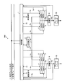
- FIG. 1 is a diagram illustrating an example of a configuration of a train brake device according to the first embodiment.
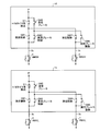
- FIG. 2 is a diagram illustrating an example of the configuration of the solenoid valve drive circuit according to the first embodiment.
- FIG. 3 is a diagram illustrating an example of the configuration of the train brake device according to the second embodiment.
- FIG. 4 is a diagram illustrating an example of the configuration of the solenoid valve drive circuit according to the second embodiment.
- FIG. 5 is a diagram illustrating an example of a logical table.
- FIG. 6 is a diagram illustrating an example of a solenoid valve drive circuit with a simplified circuit configuration.
- FIG. 7 is a diagram illustrating an example of a block diagram of a temperature control circuit of the solenoid valve.
- FIG. 1 is a diagram illustrating an example of a configuration of a train brake device according to a first embodiment of the present invention.
- a train brake device 100 shown in FIG. 1 includes, as main components, a control unit 1, a variable load valve 2, an AMV (Apply Magnet Valve) 20, an RMV (Release Magnet Valve) 21, a relay valve 9, And a brake cylinder 10.
- Each component connected to the control unit 1 is shown symmetrically about the variable load valve 2. This is because the first component connected to the control unit 1 controls the brake of the first carriage of each vehicle, and the second component controls the brake of the second carriage.
- the control unit 1 takes in the service brake command 11 transmitted from the brake command unit. Further, the control unit 1 takes in the emergency brake command 12 by a system different from the service brake command 11.
- variable load valve 2 is installed in the front and rear carriages of each vehicle, and generates an emergency brake by directly supplying the output pressure 2a of the compressed air to the relay valve 9.
- the AMV 20 supplies the output pressure 2a of the supplied compressed air to the brake cylinder 10.
- the RMV 21 regulates the output pressure 2a of the supplied compressed air.
- the constituent parts of the AMV 20 and RMV 21 are referred to as electromagnetic valve parts.
- the relay valve 9 is used to improve the responsiveness of the brake cylinder pressure 9a, and amplifies the compressed air (hereinafter referred to as “pressure control signal”) 3b supplied from the AMV 20 and the RMV 21 to a predetermined pressure.
- An original air reservoir (not shown) is connected to the relay valve 9. Since the compressed air is stored in the original air reservoir, the relay valve 9 can amplify the pressure control signal 3b and generate the brake cylinder pressure 9a for operating the brake cylinder 10.
- FIG. 2 is a diagram illustrating an example of the configuration of the solenoid valve drive circuit according to the first embodiment.
- the electromagnetic valve drive circuit 1a is a part of the internal circuit of the control unit 1, and is a circuit for driving the AMV 20 and the RMV 21.
- the solenoid valve drive circuit 1a includes, as main components, a first sliding control switch SW1, a second sliding control switch SW4, a first emergency brake switch SW2, a second emergency brake switch SW5, and a first It has a service brake control switch SW3, a second service brake control switch SW6, an H / W timer contact S1, an H / W timer contact S2, and a circuit power supply P.
- AMV 20 and RMV 21 correspond to AMV 20 and RMV 21 shown in FIG.
- the H / W timer contact S1 and the H / W timer contact S2 can protect the electromagnetic valve from excessive wear by stopping the wheel slip control safety function and the wheel slip control operation, and stop the train. The wheel slip control can be recovered without any trouble.
- the solenoid valve drive circuit 1a has a first sliding control switch SW1 or a first sliding control at both ends of a series connection circuit including a first emergency brake switch SW2 and a first service brake control switch SW3.
- a first switch circuit in which a series connection circuit of the switch SW1 and the H / W timer contact S1 is connected in parallel.
- the solenoid valve drive circuit 1a has a second sliding control switch SW4 or a second sliding control switch at both ends of a series connection circuit including a second emergency brake switch and a second service brake control switch.
- a second switch circuit is provided in which a series connection circuit of the switch SW4 and the H / W timer contact S2 is connected in parallel.
- a series connection circuit consisting of each emergency brake switch and each service brake control switch is shown. However, the switches included in this series connection circuit are only the emergency brake switch and service brake control switch. It is not limited.
- the first switch circuit has one end connected to the circuit power supply P and the other end connected to the AMV 20.
- the second switch circuit has one end connected to the first switch circuit and the other end connected to the RMV 21.
- the sliding control can be made independent from the emergency brake and the service brake control, and the RMV 21 can be driven in conjunction with the AMV 20.
- the first sliding control switch SW1 when the contact of the first sliding control switch SW1 is closed, the current of the circuit power supply P is supplied to the second switch circuit, and the second switch circuit can drive the RMV 21.
- a predetermined logic table is set in the control unit 1 in advance, and the control unit 1 sets the first service brake control switch SW3 and the second service brake control switch SW6 to OPEN or based on the logic table. CLOSE.
- the logic table indicates that the second mode for supplying compressed air and the fifth mode for exhausting compressed air are provided so that the brake cylinder pressure 9a necessary for the service brake control, the sliding control, and the emergency brake output can be obtained. Defined and used to control AMV 20 or RMV 21 under pressure control or no pressure control.
- the solenoid valve drive circuit 1a forcibly sets the first emergency brake switch SW2 and the second emergency brake switch SW5 to OPEN. Since the first sliding control switch SW1 and the second sliding control switch SW4 are OPEN, all the solenoid valves are not supplied with circuit power P and are not pressurized.
- the train brake device 100 generates an emergency brake by supplying the output pressure 2a from the variable load valve 2 to the relay valve 9.
- the electromagnetic valve drive circuit 1a opens or closes the first sliding control switch SW1 and the second sliding control switch SW4 based on the logic table, and drives the AMV 20 or RMV 21.
- the solenoid valve driving circuit 1a causes the first sliding control switch SW1 and the second sliding control switch SW4 to become OPEN by stall detection, but generates a normal brake control or an emergency brake. it can.
- the electromagnetic valve drive circuit 1a including the first switch circuit and the second switch circuit is configured to interlock the RMV 21 with the AMV 20. Therefore, unlike conventional train brake devices, emergency braking and sliding without using an emergency solenoid valve and switching solenoid valve, and without making the emergency brake circuit separate from the sliding control and regular brake switches. Control and service brake control can be performed. Moreover, since an emergency solenoid valve is unnecessary, the train brake device 100 can be reduced in size, weight, raw material weight, and cost. Furthermore, since the number of parts is reduced, the reliability of the train brake device 100 is improved and long-term use is possible.
- Embodiment 2 FIG.
- the train brake device 300 according to the second embodiment is configured to be able to finely control the brake cylinder pressure 9a by using four types of magnet valves.
- FIG. 3 is a diagram illustrating an example of the configuration of the train brake device according to the second embodiment.
- the train brake device 300 shown in FIG. 3 includes a control unit 1, a variable load valve 2, an AMVH (Apply Magnet Valve High: first supply valve) 4, an AMVL (Apply Magnet Valve Low: second supply) as main components. Valve) 5, RMVH (Release Magnet Valve High: first exhaust valve) 6, RMVL (Release Magnet Valve Low: second exhaust valve) 7, relay valve 9, and brake cylinder 10. .
- the AMVH 4 supplies the output pressure 2a of the supplied compressed air to the brake cylinder 10.
- the RMVH 6 regulates the output pressure 2a of the supplied compressed air.
- AMVL5 supplies the output pressure 2a of compressed air weaker than AMVH4.
- RMVL7 adjusts the output pressure 2a of the compressed air to be weaker than RMVH6.
- the relay valve 9 is used to improve the response of the brake cylinder pressure 9a, and amplifies the pressure control signal 3b supplied from the AMVH4, AMVL5, RMVH6, and RMVL7 to a predetermined pressure.
- FIG. 4 is a diagram illustrating an example of the configuration of the solenoid valve drive circuit according to the second embodiment.
- the first solenoid valve drive circuit 1b and the second solenoid valve drive circuit 1c are part of the internal circuit of the control unit 1, and are circuits for driving AMVH4, AMVL5, RMVH6, and RMVL7.
- the first solenoid valve drive circuit 1b and the second solenoid valve drive circuit 1c have, as main components, a first sliding control switch SW1, a second sliding control switch SW4, and a first emergency brake switch, respectively.
- SW2 second emergency brake switch SW5, first service brake control switch SW3, second service brake control switch SW6, H / W timer contact S1, H / W timer contact S2, and circuit power supply P is configured.
- AMVH4, AMVL5, RMVH6, and RMVL7 correspond to AMVH4, AMVL5, RMVH6, and RMVL7 shown in FIG.
- the first solenoid valve drive circuit 1b and the second solenoid valve drive circuit 1c are respectively connected to both ends of a series connection circuit including a first emergency brake switch SW2 and a first service brake control switch SW3.
- the first solenoid valve drive circuit 1b and the second solenoid valve drive circuit 1c are connected to both ends of a series connection circuit including a second emergency brake switch and a second service brake control switch.
- the first solenoid valve drive circuit 1b one end of the first switch circuit is connected to the circuit power source P and the other end is connected to the AMVH4.
- the second switch circuit has one end connected to the first switch circuit and the other end connected to the RMVH 6.
- the second solenoid valve drive circuit 1c one end of the first switch circuit is connected to the circuit power source P and the other end is connected to the AMVL5.
- the second switch circuit has one end connected to the first switch circuit and the other end connected to the RMVL 7.
- the train brake device 300 returns the pressure control signal 3b and the brake cylinder pressure 9a to the control unit 1. Therefore, the controller 1 drives AMVH4, AMVL5, RMVH6, and RMVL7 while recognizing the state of the pressure control signal 3b and the brake cylinder pressure 9a.
- FIG. 6 is a diagram showing an example of a solenoid valve drive circuit with a simplified circuit configuration.
- the first solenoid valve drive circuit 1d and the second solenoid valve drive circuit 1e shown in FIG. 6 have a configuration in which the second emergency brake switch SW5 shown in FIG. 4 is omitted.
- the connection between the first emergency brake switch SW2 and the first service brake control switch SW3 is connected to the second service brake control switch SW6, and the first service control switch SW1 is connected to the second service. Since the control switch SW4 is connected, each emergency brake switch SW2 can generate an emergency brake.
- AMVH4 AMVL5, RMVH6, and RMVL7 can be brought into a non-pressurized state in synchronization.
- the solenoid valve drive circuit 1a according to the first embodiment may be simplified in the same manner.
- FIG. 5 is a diagram showing an example of a logical table.
- the logic table 50 is set in the control unit 1 in advance, and is used to adjust the supply of compressed air and the strength of exhaust gas by combining the operations of AMVH4, AMVL5, RMVH6, and RMVL7.
- the logic table 50 includes items indicating the names of the respective solenoid valves and items indicating the strength of the supply and exhaust of compressed air.
- AMVH4, AMVL5, RMVH6, and RMVL7 are shown as an example.
- the items indicating the supply of compressed air and the strength of exhaust include, as an example, a first mode, a second mode, a third mode, a fourth mode, a fifth mode, a sixth mode, and a seventh mode. Modes are shown.
- the first mode shows the release state of the service brake.
- AMVH4 and AMVL5 are CLOSE
- RMVH6 and RMVL7 are OPEN.
- the output pressure 2a of compressed air is supplied.
- the AMVH4 is OPEN
- the AMVL5, RMVH6, and RMVL7 are CLOSE.
- the compressed air output pressure 2a is gently supplied, and the service brake is "finely tuned".
- the AMVH4 is in the pressurized state “ ⁇ ”
- the AMVL5 is OPEN
- the AMVH4, RMVH6, and RMVL7 are CLOSE.
- the output pressure 2a of the compressed air is exhausted.
- the RMVH6 is OPEN
- the AMVH4, AMVL5, and RMVL7 are CLOSE.
- the sixth mode exhausts the compressed air output pressure 2a more slowly than the fifth mode.
- RMVH6 is in the non-pressurized state “x”
- RMVL7 is OPEN
- AMVH4, AMVL5, and RMVH6 are CLOSE.
- the operation of each switch shown in FIG. 4 will be described.
- the first sliding control switch SW1 and the second sliding control switch SW4 are OPEN. Since the emergency brake command 12 is always a pressurization command, the first emergency brake switch SW2 and the second emergency brake switch SW5 are normally closed. Therefore, the first solenoid valve drive circuit 1b or the second solenoid valve drive circuit 1c sets the first service brake control switch SW3 and the second service brake control SW6 to OPEN or CLOSE based on the logic table 50.
- AMVH4, AMVL5, RMVH6, and RMVL7 are driven.
- the first solenoid valve drive circuit 1b or the second solenoid valve drive circuit 1c forcibly opens the first emergency brake switch SW2 and the second emergency brake switch SW5. Then, the circuit power supply P used in the service brake control is opened.
- the train brake device 300 generates an emergency brake by supplying the output pressure 2 a of compressed air from the variable load valve 2 to the relay valve 9.
- the first emergency brake switch SW2 and the second emergency brake switch SW5 are CLOSE.
- the first service brake control switch SW3 and the second service brake control switch SW6 are OPEN.
- the first solenoid valve drive circuit 1b or the second solenoid valve drive circuit 1c opens or closes the first sliding control switch SW1 and the second sliding control switch SW4, and AMVH4 , AMVL5, RMVH6, and RMVL7.
- the pressure control signal 3b output from the AMVH4, AMVL5, RMVH6, and RMVL7 and the brake cylinder pressure 9a output from the relay valve 9 are returned to the control unit 1 to re-adhere the wheel.
- the first sliding control switch SW1 and the second sliding control switch SW4 become OPEN when a stall is detected, but the normal brake control or emergency brake can be operated. It is.
- the 1b or second solenoid valve drive circuit 1c performs hysteresis correction in the third mode or the sixth mode of the logic table 50 with the brake cylinder pressure 9a as a reference.
- control unit 1 uses the pressure control signal 3b indicating the pressure of the compressed air input to the relay valve 9 and the brake cylinder pressure 9a output from the relay valve 9 to use the first electromagnetic valve drive circuit 1b and The second electromagnetic valve drive circuit 1c is controlled to reduce the hysteresis loss so as to approach the value of the brake cylinder pressure 9a determined according to the pressure of the compressed air input to the relay valve 9.
- the brake cylinder pressure 9a can be finely adjusted by using four types of magnet valves. It is possible to improve the accuracy of control and sliding control. Further, since the circuit configuration of the control unit 1 is simplified, the train brake device 300 can be reduced in size, the amount of raw materials can be reduced, and the cost can be reduced. Furthermore, since the number of parts is reduced, the reliability of the train brake device 300 is improved and long-term use is possible.
- Embodiment 3 In the train brake device according to the third embodiment, in order to improve the reliability of each electromagnetic valve, a temperature sensor and a heater can be installed in the vicinity of the electromagnetic valve to perform temperature management of the electromagnetic valve. Note that the train brake device according to the third embodiment corresponds to either the train brake device 100 or the train brake device 300.
- FIG. 7 is a diagram showing an example of a block diagram of a temperature control circuit of the solenoid valve.
- the temperature control circuit is mainly composed of a first temperature sensor A71, a second temperature sensor B72, an analog input circuit A73, an analog input circuit B74, an A / D converter A75, an A / D converter B76, an IO logic IC 77, a stall. It has a detection 78, a digital input / output circuit 79, and a heater 80.
- the first temperature sensor A71 is for measuring the temperature of the solenoid valve portion or the vicinity of the solenoid valve portion, and always measures the temperature. Similar to the first temperature sensor A71, the second temperature sensor B72 is installed in the vicinity of the electromagnetic valve portion or the electromagnetic valve portion, and monitors whether the value of the first temperature sensor A71 is normal.
- the train brake device 100 or the train brake device 300 is When the temperature is less than 10 degrees, the heater 80 is turned on to warm the solenoid valve.
- the heater 80 When the temperature in the box is high, for example, 15 degrees or more, the heater 80 is turned off to stabilize the operation of the solenoid valve. Further, when the CPU is abnormal, the heater is turned off by the stall detection 78 in order to suppress the temperature rise in the box.
- the number of the first temperature sensor A71 or the second temperature sensor B72 and the devices corresponding to each temperature sensor are not limited to two, but more first temperature sensors A71 or second ones. Two temperature sensors B72 and the like may be installed for finer temperature control.
- the ambient temperature of the solenoid valve can be kept at room temperature, so that the solenoid valve can be used for a long period of time compared to the conventional case. Moreover, since abnormal heat generation of the electromagnetic valve can be detected, the reliability of the train brake device can be improved.
- the train brake device according to the present invention is useful for a train brake device that controls the brake cylinder pressure.
Landscapes
- Engineering & Computer Science (AREA)
- Transportation (AREA)
- Mechanical Engineering (AREA)
- Braking Systems And Boosters (AREA)
- Regulating Braking Force (AREA)
- Valves And Accessory Devices For Braking Systems (AREA)
Abstract
Description
常用ブレーキ指令または非常ブレーキ指令に基づいて、ブレーキシリンダに作用するブレーキシリンダ圧力を制御する制御部を備えた列車ブレーキ装置において、供給された圧縮空気を前記ブレーキシリンダに供給する供給弁と、供給された前記圧縮空気を調圧する排気弁とを有する電磁弁部を備え、前記制御部は、第1の非常ブレーキ用スイッチと第1の常用ブレーキ制御用スイッチとを含む直列接続回路の両端に第1の滑走制御用スイッチを並列接続したスイッチ回路であって、一端が回路電源に接続され、他端が前記供給弁に接続される第1のスイッチ回路と、第2の非常ブレーキ用スイッチと第2の常用ブレーキ制御用スイッチとを含む直列接続回路の両端に第2の滑走制御用スイッチを並列接続したスイッチ回路であって、一端が前記第1のスイッチ回路の他端に接続され、他端が前記排気弁に接続される第2のスイッチ回路と、を有する電磁弁駆動回路を備えたことを特徴とする。
1a、1b、1c、1d、1e 電磁弁駆動回路
2 応荷重弁
2a 出力圧
3b 圧力制御信号
3c 制御信号
4 AMVH
5 AMVL
6 RMVH
7 RMVL
9 中継弁
9a ブレーキシリンダ圧力
10 ブレーキシリンダ
11 常用ブレーキ指令
12 非常ブレーキ指令
13 速度信号
14 荷重信号
20 AMV
21 RMV
50 論理表
71 温度センサA
72 温度センサB
73 アナログ入力回路A
74 アナログ入力回路B
75 A/DコンバータA
76 A/DコンバータB
77 IOロジックIC
78 ストール検知
79 デジタル入出力回路
80 ヒータ
100、300 列車ブレーキ装置
S1、S2 H/Wタイマ用接点
SW1、SW4 滑走制御用スイッチ
SW2、SW5 非常ブレーキ用スイッチ
SW3、SW6 常用ブレーキ制御用スイッチ
P 回路電源
図1は、本発明の実施の形態1にかかる列車ブレーキ装置の構成の一例を示す図である。図1に示す列車ブレーキ装置100は、主たる構成部として、制御部1、応荷重弁2、AMV(Apply Magnet Valve:供給弁)20、RMV(Release Magnet Valve:排気弁)21、中継弁9、およびブレーキシリンダ10を有して構成されている。制御部1に接続される各構成部は、応荷重弁2を中心に左右対称に図示されている。これは、制御部1に接続される第1の構成部が各車両の第1の台車のブレーキを制御し、第2の構成部が第2の台車のブレーキを制御するためである。
実施の形態2にかかる列車ブレーキ装置300は、4種類のマグネットバルブを使用することにより、ブレーキシリンダ圧力9aを細かく制御することができるように構成されている。
実施の形態3にかかる列車ブレーキ装置は、各電磁弁の信頼性を向上させるため、電磁弁近傍に温度センサとヒータを設置し、電磁弁の温度管理を行うことができる。なお、実施の形態3にかかる列車ブレーキ装置は列車ブレーキ装置100または列車ブレーキ装置300のいずれにも対応している。
Claims (7)
- 常用ブレーキ指令または非常ブレーキ指令に基づいて、ブレーキシリンダに作用するブレーキシリンダ圧力を制御する制御部を備えた列車ブレーキ装置において、
供給された圧縮空気を前記ブレーキシリンダに供給する供給弁と、供給された前記圧縮空気を調圧する排気弁とを有する電磁弁部を備え、
前記制御部は、
第1の非常ブレーキ用スイッチと第1の常用ブレーキ制御用スイッチとを含む直列接続回路の両端に第1の滑走制御用スイッチを並列接続したスイッチ回路であって、一端が回路電源に接続され、他端が前記供給弁に接続される第1のスイッチ回路と、
第2の非常ブレーキ用スイッチと第2の常用ブレーキ制御用スイッチとを含む直列接続回路の両端に第2の滑走制御用スイッチを並列接続したスイッチ回路であって、一端が前記第1のスイッチ回路の他端に接続され、他端が前記排気弁に接続される第2のスイッチ回路と、
を有する電磁弁駆動回路を備えたことを特徴とする列車ブレーキ装置。 - 前記供給弁は第1の供給弁および第2の供給弁から成り、前記排気弁は第1の排気弁および第2の排気弁から成り、
前記電磁弁駆動回路は、
前記圧縮空気を供給する前記第1の供給弁に前記第1のスイッチ回路の他端が接続され、前記圧縮空気を排気する前記第1の排気弁に前記第2のスイッチ回路の他端が接続された第1の電磁弁駆動回路と、
前記第1の供給弁より圧縮空気を弱く供給する前記第2の供給弁に前記第1のスイッチ回路の他端が接続され、前記第1の排気弁より圧縮空気を弱く排気する前記第2の排気弁に前記第2のスイッチ回路の他端が接続された第2の電磁弁駆動回路と、
を備えたことを特徴とする請求項1に記載の列車ブレーキ装置。 - 前記圧縮空気の供給と排気を停止する第4のモードの他に、前記圧縮空気を供給する第2のモードおよび前記第2のモードに比して供給を緩やかに行う第3のモードならびに前記圧縮空気を排気する第5のモードおよび前記第5のモードに比して排気を緩やかに行う第6のモードが定義され、
前記制御部は、
前記第3のモードを動作させる場合、前記第1の電磁弁駆動回路における前記第1のスイッチ回路に接続された前記第1の供給弁のみを加圧状態に制御し、
前記第6のモードを動作させる場合、前記第1の電磁弁駆動回路における前記第2のスイッチ回路に接続された前記第1の排気弁のみを無加圧状態に制御すること、
を特徴とする請求項2に記載の列車ブレーキ装置。 - 前記電磁弁部から供給された前記圧縮空気に応じて前記ブレーキシリンダ圧力を生成する中継弁を備え、
前記電磁弁部は、前記中継弁に供給される圧縮空気の圧力を調整し、
前記制御部は、前記中継弁に入力される前記圧縮空気の圧力と前記中継弁から出力される前記ブレーキシリンダ圧力とを用いて、前記中継弁に入力される前記圧縮空気の圧力に応じて定まるブレーキシリンダ圧力の値に近づくように第1の電磁弁駆動回路および第2の電磁弁駆動回路を制御することを特徴とする請求項2または3に記載の列車ブレーキ装置。 - 前記電磁弁駆動回路は、前記常用ブレーキ指令が出力された場合、前記常用ブレーキ制御用スイッチをクローズし、前記常用ブレーキ指令が出力されていない場合、前記常用ブレーキ制御用スイッチをオープンにすることを特徴とする請求項1ないし4のいずれか1項に記載の列車ブレーキ装置。
- 前記電磁弁駆動回路は、滑走が発生している場合、前記滑走制御用スイッチをオープンにし、滑走が発生していない場合、前記滑走制御用スイッチをクローズにすることを特徴とする請求項1ないし4のいずれか1項に記載の列車ブレーキ装置。
- 前記電磁弁部または前記電磁弁部周辺の温度を測定する第1の温度センサと、第1の温度センサを監視する第2の温度センサと、前記電磁弁部または前記電磁弁部周辺の温度を調整するヒータとを有する温度制御回路を備え、
前記温度制御回路は、前記第1の温度センサの値と前記第2の温度センサの値との所定差に応じて前記ヒータを制御することを特徴とする請求項1ないし6のいずれか1項に記載の列車ブレーキ装置。
Priority Applications (8)
| Application Number | Priority Date | Filing Date | Title |
|---|---|---|---|
| ES08791560T ES2390174T3 (es) | 2008-07-24 | 2008-07-24 | Dispositivo de frenado de tren |
| PCT/JP2008/063308 WO2010010623A1 (ja) | 2008-07-24 | 2008-07-24 | 列車ブレーキ装置 |
| CN2008801305160A CN102099233B (zh) | 2008-07-24 | 2008-07-24 | 列车制动装置 |
| US12/999,207 US8646853B2 (en) | 2008-07-24 | 2008-07-24 | Train braking device |
| EP08791560A EP2330006B1 (en) | 2008-07-24 | 2008-07-24 | Train braking device |
| CA2731570A CA2731570C (en) | 2008-07-24 | 2008-07-24 | Train braking device |
| KR1020107029028A KR101182465B1 (ko) | 2008-07-24 | 2008-07-24 | 열차 브레이크 장치 |
| JP2010521565A JP4606519B2 (ja) | 2008-07-24 | 2008-07-24 | 列車ブレーキ装置 |
Applications Claiming Priority (1)
| Application Number | Priority Date | Filing Date | Title |
|---|---|---|---|
| PCT/JP2008/063308 WO2010010623A1 (ja) | 2008-07-24 | 2008-07-24 | 列車ブレーキ装置 |
Publications (1)
| Publication Number | Publication Date |
|---|---|
| WO2010010623A1 true WO2010010623A1 (ja) | 2010-01-28 |
Family
ID=41570102
Family Applications (1)
| Application Number | Title | Priority Date | Filing Date |
|---|---|---|---|
| PCT/JP2008/063308 Ceased WO2010010623A1 (ja) | 2008-07-24 | 2008-07-24 | 列車ブレーキ装置 |
Country Status (8)
| Country | Link |
|---|---|
| US (1) | US8646853B2 (ja) |
| EP (1) | EP2330006B1 (ja) |
| JP (1) | JP4606519B2 (ja) |
| KR (1) | KR101182465B1 (ja) |
| CN (1) | CN102099233B (ja) |
| CA (1) | CA2731570C (ja) |
| ES (1) | ES2390174T3 (ja) |
| WO (1) | WO2010010623A1 (ja) |
Families Citing this family (22)
| Publication number | Priority date | Publication date | Assignee | Title |
|---|---|---|---|---|
| US20120296501A1 (en) * | 2010-01-21 | 2012-11-22 | Mitsubishi Electric Corporation | Brake control device and brake control method |
| CN103068645A (zh) * | 2010-08-11 | 2013-04-24 | 纳博特斯克有限公司 | 气动制动装置的控制方法 |
| ES2461843T3 (es) | 2010-12-23 | 2014-05-21 | Biedermann Technologies Gmbh & Co. Kg | Dispositivo de anclaje de hueso |
| CN102225693B (zh) * | 2011-04-25 | 2016-04-13 | 浙江金字机械电器有限公司 | 列车气路控制器 |
| DE102011110047A1 (de) * | 2011-08-12 | 2013-02-14 | Knorr-Bremse Systeme für Schienenfahrzeuge GmbH | Notbremseinrichtung für ein Schienenfahrzeug, Bremsanlage für ein Schienenfahrzeug sowie Schienenfahrzeug |
| DE102011113093A1 (de) * | 2011-09-09 | 2013-03-14 | Knorr-Bremse Systeme für Schienenfahrzeuge GmbH | Bremswirkungsbestimmung für ein Schienenfahrzeug |
| GB2502252B (en) * | 2012-03-26 | 2018-09-05 | Knorr Bremse Rail Systems Uk Ltd | Emergency braking |
| DE102012009427B4 (de) * | 2012-05-11 | 2013-11-21 | Knorr-Bremse Systeme für Schienenfahrzeuge GmbH | Steuerventileinrichtung für eine Schienenfahrzeugbremse |
| DE102012013523A1 (de) * | 2012-07-06 | 2014-01-09 | Knorr-Bremse Systeme für Schienenfahrzeuge GmbH | Steuerventil mit einer Einrichtung zur Erzeugung definierter Brems- und Lösezeiten |
| JP5900891B2 (ja) * | 2013-04-26 | 2016-04-06 | 三菱電機株式会社 | ブレーキ制御装置およびブレーキ制御方法 |
| CN103935380B (zh) * | 2014-04-25 | 2016-03-09 | 南车株洲电力机车有限公司 | 一种机车空气防滑系统的控制方法和装置 |
| CN104260745A (zh) * | 2014-09-28 | 2015-01-07 | 青岛思锐科技有限公司 | 动车组制动控制单元 |
| US12509037B2 (en) | 2014-11-13 | 2025-12-30 | Faiveley Transport Italia S.P.A. | Vehicle braking assembly |
| CN107107897B (zh) * | 2014-11-13 | 2019-08-09 | 法伊韦利传送器意大利有限公司 | 具体用于铁路运载工具的气动制动安装的电动气动组件 |
| ITUB20152413A1 (it) | 2015-07-22 | 2017-01-22 | Faiveley Transport Italia Spa | Sistema pneumatico di frenatura per un veicolo ferroviario, con elettrovalvola di rilascio della frenatura. |
| CN105128839B (zh) * | 2015-09-28 | 2018-07-06 | 中车资阳机车有限公司 | 一种机车无线遥控系统 |
| CN106427959A (zh) * | 2016-07-15 | 2017-02-22 | 青岛雷尔威机械制造有限公司 | 一种防滑器主机装置 |
| CN109649430A (zh) * | 2019-01-25 | 2019-04-19 | 中车青岛四方机车车辆股份有限公司 | 一种列车制动隔离的设备、方法及系统 |
| EP3766443B1 (en) | 2019-07-18 | 2023-02-15 | Biedermann Technologies GmbH & Co. KG | Bone anchoring device |
| CN113212400A (zh) * | 2021-06-10 | 2021-08-06 | 中车长春轨道客车股份有限公司 | 一种列车紧急制动控制电路及方法 |
| ES2989275T3 (es) * | 2022-07-04 | 2024-11-25 | Dellner Bubenzer Ab | Controlador para estimar los pesos individuales de los ejes de un vehículo ferroviario, procedimiento implementado por ordenador para este, programa informático y portadora de datos no volátil |
| KR102534280B1 (ko) | 2022-11-08 | 2023-05-26 | 주식회사 주은기공 | 열차의 제동을 제어하는 장치 및 방법 |
Citations (5)
| Publication number | Priority date | Publication date | Assignee | Title |
|---|---|---|---|---|
| JPS5674701A (en) * | 1979-11-22 | 1981-06-20 | Toshiba Corp | Double system switching decision apparatus of process computer |
| JPH0478069U (ja) * | 1990-11-21 | 1992-07-08 | ||
| JPH0867240A (ja) * | 1994-08-30 | 1996-03-12 | Nabco Ltd | ブレーキ装置 |
| JPH10338123A (ja) * | 1997-06-06 | 1998-12-22 | Nabco Ltd | 鉄道車両用ブレーキ装置 |
| JP2001018784A (ja) | 1999-07-02 | 2001-01-23 | Mitsubishi Electric Corp | 電気車の空気ブレーキ装置及び空気ブレーキ方法 |
Family Cites Families (12)
| Publication number | Priority date | Publication date | Assignee | Title |
|---|---|---|---|---|
| US4598953A (en) * | 1985-06-17 | 1986-07-08 | American Standard Inc. | Electropneumatic brake control system for railway transit vehicle |
| US5222788A (en) * | 1991-09-16 | 1993-06-29 | Westinghouse Air Brake Company | Microprocessor based electro-pneumatic locomotive brake control system having brake assurance circuit |
| JPH05155327A (ja) | 1991-12-05 | 1993-06-22 | Railway Technical Res Inst | 電磁自動空気ブレーキ方式及び装置 |
| JP2593787B2 (ja) | 1993-09-29 | 1997-03-26 | 株式会社ナブコ | 非常ブレーキ読換装置 |
| US5758929A (en) * | 1996-09-11 | 1998-06-02 | New York Air Brake Corporation | Variable capacity electropneumatic control valve |
| US5887953A (en) * | 1997-01-28 | 1999-03-30 | Westinghouse Air Brake Company | Dual pneumatic trainline control unit |
| US5791744A (en) * | 1997-01-28 | 1998-08-11 | Westinghouse Air Brake Company | Pneumatic trainline control unit |
| GB9820526D0 (en) * | 1998-09-21 | 1998-11-11 | Westinghouse Brake & Signal | Controlling a braking system |
| DE59914512D1 (de) * | 1998-10-23 | 2007-11-08 | Knorr Bremse Systeme | Bremssystem für ein schienenfahrzeug |
| CN2706750Y (zh) * | 2004-06-04 | 2005-06-29 | 郑州三瑞电子技术有限公司 | 微机控制列车制动机试验系统 |
| US7240970B2 (en) * | 2005-09-14 | 2007-07-10 | New York Air Brake Corporation | Trail locomotive brake control |
| CN100475619C (zh) * | 2006-06-07 | 2009-04-08 | 吴萌岭 | 微机控制模拟式直通电空气液转换列车制动系统 |
-
2008
- 2008-07-24 WO PCT/JP2008/063308 patent/WO2010010623A1/ja not_active Ceased
- 2008-07-24 EP EP08791560A patent/EP2330006B1/en active Active
- 2008-07-24 CN CN2008801305160A patent/CN102099233B/zh active Active
- 2008-07-24 KR KR1020107029028A patent/KR101182465B1/ko not_active Expired - Fee Related
- 2008-07-24 ES ES08791560T patent/ES2390174T3/es active Active
- 2008-07-24 US US12/999,207 patent/US8646853B2/en not_active Expired - Fee Related
- 2008-07-24 CA CA2731570A patent/CA2731570C/en not_active Expired - Fee Related
- 2008-07-24 JP JP2010521565A patent/JP4606519B2/ja active Active
Patent Citations (5)
| Publication number | Priority date | Publication date | Assignee | Title |
|---|---|---|---|---|
| JPS5674701A (en) * | 1979-11-22 | 1981-06-20 | Toshiba Corp | Double system switching decision apparatus of process computer |
| JPH0478069U (ja) * | 1990-11-21 | 1992-07-08 | ||
| JPH0867240A (ja) * | 1994-08-30 | 1996-03-12 | Nabco Ltd | ブレーキ装置 |
| JPH10338123A (ja) * | 1997-06-06 | 1998-12-22 | Nabco Ltd | 鉄道車両用ブレーキ装置 |
| JP2001018784A (ja) | 1999-07-02 | 2001-01-23 | Mitsubishi Electric Corp | 電気車の空気ブレーキ装置及び空気ブレーキ方法 |
Non-Patent Citations (1)
| Title |
|---|
| See also references of EP2330006A4 * |
Also Published As
| Publication number | Publication date |
|---|---|
| CN102099233A (zh) | 2011-06-15 |
| US20110089755A1 (en) | 2011-04-21 |
| JP4606519B2 (ja) | 2011-01-05 |
| JPWO2010010623A1 (ja) | 2012-01-05 |
| ES2390174T3 (es) | 2012-11-07 |
| CA2731570C (en) | 2013-01-08 |
| KR101182465B1 (ko) | 2012-09-12 |
| CN102099233B (zh) | 2013-10-23 |
| KR20110014218A (ko) | 2011-02-10 |
| EP2330006A4 (en) | 2011-08-17 |
| EP2330006A1 (en) | 2011-06-08 |
| US8646853B2 (en) | 2014-02-11 |
| EP2330006B1 (en) | 2012-06-27 |
| CA2731570A1 (en) | 2010-01-28 |
Similar Documents
| Publication | Publication Date | Title |
|---|---|---|
| JP4606519B2 (ja) | 列車ブレーキ装置 | |
| JP6254576B2 (ja) | 非常ブレーキ | |
| EP2338749B1 (en) | Railcar brake control device | |
| CN108290563B (zh) | 具有附加控制回路的车辆电子气动式驻车制动装置 | |
| JP5538398B2 (ja) | パーキングブレーキ装置 | |
| US11932219B2 (en) | Control device and method for controlling an actuator for actuating braking means of a vehicle, more particularly of a rail vehicle | |
| EP2505451B1 (en) | Brake controller | |
| CN114761294B (zh) | 单稳态和容错设计的驻车制动阀组件 | |
| JPS61244658A (ja) | 電気車用空気ブレ−キ制御装置 | |
| US20120286563A1 (en) | Brake arrangement of a rail vehicle | |
| US10471940B2 (en) | Compressed air brake device for a rail vehicle with a direct electropneumatic brake | |
| US20070057569A1 (en) | Trail locomotive brake control | |
| JP3586140B2 (ja) | 電気車の空気ブレーキ装置及び空気ブレーキ方法 | |
| EP1259408B1 (en) | Controlling pressure in brake actuation outputs | |
| CN100389993C (zh) | 轨道车辆刹车装置 | |
| JP2857068B2 (ja) | ブレーキ装置 | |
| US6746087B1 (en) | Electronic equalizing reservoir controller with pneumatic penalty override | |
| WO2021022904A1 (zh) | 一种轨道车辆制动压力控制装置及其控制方法 | |
| CN117734647A (zh) | 一种列车电空联合制动方法 | |
| JP2857067B2 (ja) | ブレーキ装置 | |
| US5803554A (en) | Brake monitoring device for railroad cars | |
| US7527340B2 (en) | Apparatus for controlling a braking system | |
| US6896339B2 (en) | Methods and system for controlling latching exhaust valves | |
| US9725080B1 (en) | Parking brake system for locomotive |
Legal Events
| Date | Code | Title | Description |
|---|---|---|---|
| WWE | Wipo information: entry into national phase |
Ref document number: 200880130516.0 Country of ref document: CN |
|
| 121 | Ep: the epo has been informed by wipo that ep was designated in this application |
Ref document number: 08791560 Country of ref document: EP Kind code of ref document: A1 |
|
| ENP | Entry into the national phase |
Ref document number: 2010521565 Country of ref document: JP Kind code of ref document: A |
|
| WWE | Wipo information: entry into national phase |
Ref document number: 12999207 Country of ref document: US |
|
| ENP | Entry into the national phase |
Ref document number: 20107029028 Country of ref document: KR Kind code of ref document: A |
|
| WWE | Wipo information: entry into national phase |
Ref document number: 2008791560 Country of ref document: EP |
|
| ENP | Entry into the national phase |
Ref document number: 2731570 Country of ref document: CA |
|
| NENP | Non-entry into the national phase |
Ref country code: DE |