WO2010010896A1 - Composant de transmission de puissance, mécanisme d'amortissement et ensemble volant - Google Patents
Composant de transmission de puissance, mécanisme d'amortissement et ensemble volant Download PDFInfo
- Publication number
- WO2010010896A1 WO2010010896A1 PCT/JP2009/063105 JP2009063105W WO2010010896A1 WO 2010010896 A1 WO2010010896 A1 WO 2010010896A1 JP 2009063105 W JP2009063105 W JP 2009063105W WO 2010010896 A1 WO2010010896 A1 WO 2010010896A1
- Authority
- WO
- WIPO (PCT)
- Prior art keywords
- rotating body
- spring
- power transmission
- main body
- damper mechanism
- Prior art date
- Legal status (The legal status is an assumption and is not a legal conclusion. Google has not performed a legal analysis and makes no representation as to the accuracy of the status listed.)
- Ceased
Links
Images


Classifications
-
- F—MECHANICAL ENGINEERING; LIGHTING; HEATING; WEAPONS; BLASTING
- F16—ENGINEERING ELEMENTS AND UNITS; GENERAL MEASURES FOR PRODUCING AND MAINTAINING EFFECTIVE FUNCTIONING OF MACHINES OR INSTALLATIONS; THERMAL INSULATION IN GENERAL
- F16F—SPRINGS; SHOCK-ABSORBERS; MEANS FOR DAMPING VIBRATION
- F16F15/00—Suppression of vibrations in systems; Means or arrangements for avoiding or reducing out-of-balance forces, e.g. due to motion
- F16F15/10—Suppression of vibrations in rotating systems by making use of members moving with the system
- F16F15/12—Suppression of vibrations in rotating systems by making use of members moving with the system using elastic members or friction-damping members, e.g. between a rotating shaft and a gyratory mass mounted thereon
- F16F15/131—Suppression of vibrations in rotating systems by making use of members moving with the system using elastic members or friction-damping members, e.g. between a rotating shaft and a gyratory mass mounted thereon the rotating system comprising two or more gyratory masses
- F16F15/133—Suppression of vibrations in rotating systems by making use of members moving with the system using elastic members or friction-damping members, e.g. between a rotating shaft and a gyratory mass mounted thereon the rotating system comprising two or more gyratory masses using springs as elastic members, e.g. metallic springs
- F16F15/134—Wound springs
-
- Y—GENERAL TAGGING OF NEW TECHNOLOGICAL DEVELOPMENTS; GENERAL TAGGING OF CROSS-SECTIONAL TECHNOLOGIES SPANNING OVER SEVERAL SECTIONS OF THE IPC; TECHNICAL SUBJECTS COVERED BY FORMER USPC CROSS-REFERENCE ART COLLECTIONS [XRACs] AND DIGESTS
- Y10—TECHNICAL SUBJECTS COVERED BY FORMER USPC
- Y10T—TECHNICAL SUBJECTS COVERED BY FORMER US CLASSIFICATION
- Y10T74/00—Machine element or mechanism
- Y10T74/21—Elements
- Y10T74/2121—Flywheel, motion smoothing-type
- Y10T74/2131—Damping by absorbing vibration force [via rubber, elastomeric material, etc.]
-
- Y—GENERAL TAGGING OF NEW TECHNOLOGICAL DEVELOPMENTS; GENERAL TAGGING OF CROSS-SECTIONAL TECHNOLOGIES SPANNING OVER SEVERAL SECTIONS OF THE IPC; TECHNICAL SUBJECTS COVERED BY FORMER USPC CROSS-REFERENCE ART COLLECTIONS [XRACs] AND DIGESTS
- Y10—TECHNICAL SUBJECTS COVERED BY FORMER USPC
- Y10T—TECHNICAL SUBJECTS COVERED BY FORMER US CLASSIFICATION
- Y10T74/00—Machine element or mechanism
- Y10T74/21—Elements
- Y10T74/2121—Flywheel, motion smoothing-type
- Y10T74/2132—Structural detail, e.g., fiber, held by magnet, etc.
Definitions
- the present invention relates to a power transmission component, a damper mechanism, and a flywheel assembly for transmitting rotational power.
- a clutch device or a flywheel assembly can be considered.
- a damper mechanism is used for the purpose of damping rotational vibration (see, for example, Patent Documents 1 and 2).
- This type of damper mechanism has, for example, an input member, an output member, a plurality of springs that elastically connect the input member and the output member in the rotational direction, and a spring seat that supports the end of the spring. is doing.
- the input member and the output member are power transmission components.
- the conventional damper mechanism is provided with a friction generating mechanism in order to enhance vibration damping performance.
- the friction generating mechanism includes a bush, a friction plate, and a cone spring.
- the bush is disposed so as to rotate integrally with the input member.
- the friction plate is disposed so as to rotate integrally with the output member.
- the cone spring is disposed between the bush and the input member in the axial direction, and presses the bush and the friction plate against the output member.
- the friction plate slides with the bush, and a frictional resistance is generated in the rotation direction. Due to this frictional resistance, a hysteresis torque acts between the input member and the output member, and the rotational vibration is effectively attenuated.
- the flywheel assembly includes a first flywheel, a second flywheel, and a damper mechanism.
- the first flywheel is fixed to the crankshaft of the engine.
- the damper mechanism elastically connects the first flywheel and the second flywheel in the rotational direction.
- a ring gear is fixed to the first flywheel to apply power to the crankshaft when the engine is started.
- the movement of the spring seat in the radial direction is not sufficiently restricted, so that the operation of the spring seat is difficult to stabilize.
- the vibration damping performance of the damper mechanism is not stable.
- a first problem of the present invention is to provide a power transmission component and a damper mechanism that can ensure a large power transmission area while suppressing an increase in weight.
- a second object of the present invention is to provide a damper mechanism that can enhance vibration damping performance while preventing an increase in size.
- a third object of the present invention is to provide a power transmission component and a flywheel assembly that can reduce the manufacturing cost.
- a fourth problem of the present invention is to provide a damper mechanism that can stabilize vibration damping performance.
- a fifth problem of the present invention is to provide a damper mechanism that can reduce the wear of the spring seat.
- the power transmission component according to the first feature is a component for transmitting power, and includes an annular main body portion and a plate-shaped transmission portion.
- the transmission portion includes a first protrusion that extends radially outward from the main body, and a second protrusion that extends from the circumferential end of the first protrusion to the first side in the axial direction.
- the second protrusion extends from the circumferential end of the first protrusion to the first side in the axial direction, for example, a large power transmission area of the second protrusion can be ensured. it can.
- the transmission portion is plate-shaped, it is possible to suppress an increase in the weight of the power transmission component.
- a damper mechanism includes a first rotating body, a second rotating body, a first member, a second member, a first friction member, a second friction member, and a pressing member. ing.
- the second rotating body is arranged to be rotatable with respect to the first rotating body.
- the first member is provided so as to be integrally rotatable with the first rotating body.
- the second member is provided so as to be able to rotate integrally with the second rotating body.
- the first friction member is sandwiched between the first member and the second member in the axial direction, and is provided to be rotatable with respect to the first member and the second member.
- the second friction member is sandwiched between the first member and the second rotating body in the axial direction, and is provided to be rotatable with respect to the first member and the second rotating body.
- the pressing member presses the second member against the second rotating body side in the axial direction.
- the first friction member is sandwiched between the axial directions of the first member and the second member, and the second friction member is sandwiched between the axial directions of the first member and the second rotating body. Therefore, the friction surface can be increased. For this reason, the vibration damping performance of the damper mechanism can be enhanced without increasing the radial dimension of the first friction member or the second friction member.
- the power transmission component according to the third feature is a component for transmitting power, and includes a ring member and a plate member.
- the plate member includes a disk-shaped main body portion and a plurality of support protrusions that are portions for positioning the ring member with respect to the main body portion and protrude in the axial direction from the main body portion.
- the ring member can be easily positioned with respect to the plate member. That is, it is possible to position the ring member only by forming the support protrusion, and to reduce the manufacturing cost.
- the manufacturing cost can be reduced.
- the damper mechanism includes a first rotating body, a second rotating body, a spring, and a spring seat.
- the first rotating body has a pair of first inclined surfaces inclined with respect to the radial direction.
- the second rotating body is arranged to be rotatable with respect to the first rotating body.
- the spring elastically connects the first rotating body and the second rotating body in the rotation direction.
- the spring seat is a member that supports the end portion of the spring, and has a pair of second inclined surfaces that are inclined with respect to the radial direction and are slidable with the pair of first inclined surfaces. .
- a damper mechanism includes a first rotating body, a second rotating body, at least one spring, and a first spring seat.
- the second rotating body is arranged to be rotatable with respect to the first rotating body.
- the spring elastically connects the first rotating body and the second rotating body in the rotational direction, and is arranged so as to act in series between the first rotating body and the second rotating body.
- the first spring seat is disposed between the rotation direction of the first end of the spring and the second rotator, and is in contact with the second rotator in the rotation direction.
- the contact area between the first spring seat and the second rotating body is 250 mm 2 or more.
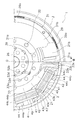
- FIG. 3 Top view of flywheel assembly II-II sectional view of FIG. Top view of flywheel assembly Top view of flywheel assembly
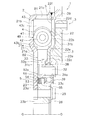
- FIG. 3 VI-VI cross section of Fig. 4
- the flywheel assembly 1 will be described with reference to FIGS. 2, 5 and 6, an engine (not shown) is arranged on the left side, and a transmission (not shown) is arranged on the right side.
- the left side in FIGS. 2, 5, and 6 is referred to as the engine side (an example of the first axial direction), and the right side is referred to as the transmission side.
- the flywheel assembly 1 is a device for transmitting power generated by an engine to a transmission via a clutch device (not shown).
- the flywheel assembly 1 includes a first flywheel 2 (an example of a first rotating body), a second flywheel 3 (an example of a second rotating body), a damper mechanism 4, and a friction generating mechanism 5. ing.
- the first flywheel 2 is a member to which power generated by the engine is input, and is fixed to a crankshaft (not shown) of the engine by a bolt 28.
- the first flywheel 2 has a first plate 21, a second plate 22, a support member 23, and a pressing plate 26.
- the first plate 21 includes a first plate body 21a, two first side parts 21b, and a cylindrical part 21c extending in the axial direction from the outer periphery of the first plate body 21a and the first side part 21b. Have.
- the first side portion 21b is a portion that protrudes closer to the engine side than the first plate body 21a, and is formed by, for example, pressing.
- the two first side portions 21b are arranged at an equal pitch in the rotation direction.
- the first side portion 21b is formed in a range corresponding to four spring sets 49 (described later).
- An inclined surface 21e (an example of a first inclined surface) that is inclined with respect to the axial direction is formed on the inner peripheral portion of the first side portion 21b.
- the inclined surface 21e is slidable with a first inclined sliding surface 44d (described later) of the first spring seat 44 and a second inclined sliding surface 43d (described later) of the second spring seat 43.
- the second plate 22 is an annular member fixed to the cylindrical portion 21c, and includes a second plate main body 22a, two second side portions 22b, an inner cylindrical portion 22c, and a plurality of support protrusions 22d. And a plurality of recesses 22f.
- the second side portion 22b is a portion that protrudes closer to the transmission side than the second plate main body 22a, and is formed by, for example, pressing.
- the two second side portions 22b are arranged at an equal pitch in the rotation direction.
- the second side portion 22b is formed in a range corresponding to four spring sets 49 (described later).
- An inclined surface 22e (an example of a first inclined surface) that is inclined with respect to the axial direction is formed on the inner peripheral portion of the second side portion 22b.
- the inclined surface 22e is a surface that forms a pair with the inclined surface 21e, and includes a first inclined sliding surface 44d (described later) of the first spring seat 44 and a second inclined sliding surface 43d (described later) of the second spring seat 43. It is slidable.
- the second side portion 22b is disposed so as to face the first side portion 21b in the axial direction, a relatively wide space in which the spring set 49 is disposed on the outer peripheral portion of the first flywheel 2 is provided in the first side portion. 21b and the second side portion 22b. Further, as shown in FIG. 9, the end of the first side portion 21b in the rotation direction and the end of the second side portion 22b in the rotation direction can contact the first spring seat 44 in the rotation direction.
- the first spring seat 44 is supported in the rotational direction by the first side portion 21b and the second side portion 22b.
- a portion of the first flywheel 2 that supports the first spring seat 44 in the rotation direction is referred to as a support portion 2a.
- the support protrusion 22d protrudes from the second side portion 22b to the transmission side, and is formed by, for example, embossing. Along with the processing of the support protrusion 22d, a recess 22f recessed toward the transmission is formed on the opposite side of the support protrusion 22d in the axial direction.
- the plurality of support protrusions 22d are arranged at an equal pitch in the circumferential direction, and the plurality of recesses 22f are also arranged at an equal pitch in the circumferential direction.
- the inner cylindrical portion 22c is a cylindrical portion extending from the inner peripheral portion of the second plate main body 22a to the engine side, and is in contact with a seal ring 38 (described later).
- the support member 23 includes an annular support member main body 23a, an annular protrusion 23b, and an annular sliding portion 23c.
- the support member main body 23 a is fixed to the crankshaft by bolts 28 together with the first plate 21.
- the annular protrusion 23b is an annular portion that protrudes from the inner peripheral portion of the support member main body 23a toward the engine, and positions the first plate 21 in the radial direction.
- the sliding portion 23 c is a portion extending in the radial direction from the support member main body 23 a and slides with the second bush 55 of the friction generating mechanism 5.
- a bearing 39 is fitted on the outer periphery of the support member main body 23a.
- the pressing plate 26 is a member for pressing the bearing 39 in the axial direction, and is fixed to the crankshaft by bolts 28 together with the first plate 21 and the support member 23.
- the 2nd flywheel 3 is a member arranged so that rotation to the 1st flywheel 2 is carried out, and has the 2nd flywheel main part 31 and output plate 33 (an example of power transmission parts). .
- the second flywheel 3 is supported by a bearing 39 so as to be rotatable with respect to the first flywheel 2.
- the second flywheel main body 31 is an annular member disposed on the transmission side of the second plate 22 and includes a support portion 31a and a friction portion 31b.
- the support portion 31 a is an annular portion that is rotatably supported by the bearing 39 with respect to the first flywheel 2, and is disposed on the inner peripheral side of the second plate 22.
- a seal ring 38 is fitted in the groove 31c of the support portion 31a.
- the housing space S of the first flywheel 2 and the space outside the first flywheel 2 are sealed by the seal ring 38.
- the accommodation space S is filled with lubricating oil.
- An output plate 33 is fixed to the support portion 31 a by rivets 32.
- the friction portion 31b is an annular portion to which a friction facing (not shown) of the clutch disk assembly is pressed, and is provided on the outer peripheral portion of the support portion 31a.
- the friction part 31b is disposed on the transmission side of the second plate 22, and protrudes closer to the transmission side than the support part 31a.
- the output plate 33 is disposed in the accommodation space S and is fixed to the support portion 31a.
- the output plate 33 has an annular main body portion 33a and two transmission portions 33e extending in the radial direction from the main body portion 33a.
- the main body portion 33a is an annular portion fixed to the support portion 31a.
- a plurality of notches 33d arranged at equal pitches in the circumferential direction are formed in the inner peripheral portion of the main body portion 33a.
- a protrusion 52b (described later) of the second friction plate 52 is inserted into the notch 33d. Thereby, the 2nd friction plate 52 and the 2nd flywheel 3 can rotate integrally.
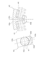
- the transmission portion 33e is a portion to which the power transmitted to the first flywheel 2 is transmitted through the four spring sets 49, and includes a first protrusion 33c and a pair of second protrusions 33b. ing.
- the 1st protrusion part 33c and the 2nd protrusion part 33b are shape
- the first projecting portion 33c is a plate-like portion that projects radially outward from the main body portion 33a.
- the first protruding portion 33c is formed so as to protrude toward the axial transmission side from the central portion 33h (an example of the first protruding portion main body) disposed at the same axial position as the main body portion 33a.
- a pair of outer portions 33i are disposed on both sides in the rotation direction of the central portion 33h.
- the second projecting portion 33b is a portion extending from the rotational end of the first projecting portion 33c (more specifically, the outer portion 33i) to the axial engine side, and includes a contact portion 33f, a reinforcing portion 33g, have.
- the contact portion 33f is a portion extending in the radial direction, and has a contact surface 33j that can contact a first spring seat 44 (described later) in the rotation direction.
- the thickness direction of the contact portion 33f (the normal direction of the contact surface 33j) is substantially coincident with the rotation direction.
- the reinforcing portion 33g is a portion that connects the radially inner end portion of the contact portion 33f and the outer peripheral portion of the main body portion 33a, and the contact surface 33j faces from the radially inner end portion of the contact portion 33f. It extends to the side. As shown in FIGS. 3 and 4, the reinforcing portion 33g has a curved portion.
- the axial dimension of the reinforcing part 33g is the same as the axial dimension of the contact part 33f. Since the outer portion 33i protrudes closer to the transmission side than the central portion 33h, the axial dimension L of the abutting portion 33f can be secured relatively large. Thereby, the area of the contact surface 33j can be set large. In particular, the contact area between the contact portion 33f and the first spring seat 44 is ensured to be 250 mm 2 or more.
- the damper mechanism 4 is a mechanism that elastically connects the first flywheel 2 and the second flywheel 3 in the rotational direction, and includes eight spring sets 49, four first spring seats 44, and six second springs. And a sheet 43.
- the damper mechanism 4 also includes the first plate 21, the second plate 22, and the output plate 33 described above.
- the spring set 49 includes a first spring 41 and a second spring 42.
- a second spring 42 is arranged inside the first spring 41 so as to act in parallel.
- Four spring sets 49 are arranged in the first compressed portion B1 formed by the first side portion 21b, the second side portion 22b, and the tubular portion 21c so as to act in series in a pre-compressed state. Yes.
- the first spring seat 44 disposed between the spring set 49 and the transmission portion 33e includes an end portion in the rotation direction of the first side portion 21b and an end portion in the rotation direction of the second side portion 22b. It is in contact with the rotation direction.
- the first spring seat 44 includes a first seat body 44c, a first outer support portion 44a, and a first inner support portion 44b.
- the first seat body 44c supports the end of the spring set 49 in the rotational direction.
- the first outer support portion 44a is a portion extending in the rotational direction from the radially outer portion of the first seat body 44c, and supports the end portion of the spring set 49 in the radial direction.
- the first outer support portion 44 a is slidable with the cylindrical portion 21 c of the first plate 21.
- 1st inner side support part 44b is a part extended in the rotation direction from the radial direction inner side part of the 1st sheet
- the end portions of the spring set 49 are supported not only in the radial direction but also in the axial direction by the first inner support portion 44b and the first outer support portion 44a.
- the first inner support portion 44b is shorter in the rotational direction than the first outer support portion 44a.
- the first inner support portion 44b has a pair of first inclined sliding surfaces 44d (an example of a second inclined surface) disposed so as to be symmetrical on both axial sides of the first inner support portion 44b. .
- the first inclined sliding surface 44d is inclined with respect to the axial direction and the radial direction, and is formed over the entire rotational direction of the first inner support portion 44b.
- the first inclined sliding surface 44d is inclined by about 45 degrees with respect to the rotation axis.
- the first inclined sliding surface 44d is slidable with the inclined surface 21e.
- a second spring seat 43 is disposed between the spring sets 49.
- the second spring seat 43 includes a second seat body 43c, a second outer support portion 43a, and a second inner support portion 43b.
- the second sheet body 43c supports the end of the spring set 49 in the rotational direction.
- the second sheet body 43c supports the end of the spring set 49 in the rotational direction.
- the second outer support portion 43a is a portion that extends from the radially outer portion of the second seat body 43c to both sides in the rotational direction, and supports the end of the spring set 49 in the radial direction.
- the second outer support portion 43a is slidable with the cylindrical portion 21c.
- the second inner support portion 43b is a portion extending from the radially inner portion of the second seat body 43c to both sides in the rotational direction, and supports the end portion of the spring set 49 in the radial direction.
- the end portions of the spring set 49 are supported not only in the radial direction but also in the axial direction by the second inner support portion 43b and the second outer support portion 43a.
- the second inner support portion 43b is shorter in the rotational direction than the second outer support portion 43a.
- the second inner support portion 43b has a pair of second inclined sliding surfaces 43d (an example of a second inclined surface) disposed so as to be symmetrical on both axial sides of the second inner support portion 43b. .
- the second inclined sliding surface 43d is inclined with respect to the axial direction and the radial direction, and is formed over the entire rotational direction of the second inner support portion 43b.
- the second inclined sliding surface 43d is inclined by about 45 degrees with respect to the rotation axis.
- the second inclined sliding surface 43d is slidable with the inclined surface 21e.
- the spring set 49, the first spring seat 44 and the second spring seat 43 are accommodated in the accommodating space S of the first flywheel 2. Specifically, the spring set 49, the first spring seat 44, and the second spring seat 43 are in the first housing portion B1 formed by the first side portion 21b, the cylindrical portion 21c, and the second side portion 22b. Has been placed.
- the above-described pair of inclined surfaces 21e is formed in the second housing portion B2 that is narrower in the axial direction than the first housing portion B1. For this reason, the first spring seat 44 and the second spring seat 43 can move in the first accommodating portion B1 in the rotational direction in a state where movement in the axial direction and the radial direction with respect to the first flywheel 2 is restricted. ing.
- the friction generating mechanism 5 is a mechanism for generating a rotational force between the first flywheel 2 and the second flywheel 3, and includes a first friction plate 53, a second friction plate 52, The first bush 54, the second bush 55, and the cone spring 51 are provided.
- the first friction plate 53 is disposed so as to be able to rotate integrally with the first flywheel 2, and is disposed on the engine side of the first bush 54.
- the second friction plate 52 is disposed so as to be rotatable integrally with the second flywheel 3, and has an annular plate body 52 a (an example of a first member body) and a plurality of protrusions protruding radially outward from the plate body 52 a. 52b.
- the plate body 52 a is disposed between the first bush 54 and the second bush 55 in the axial direction, and is slidable with the first bush 54 and the second bush 55.
- the protrusion 52b is inserted into the aforementioned notch 33d.
- the first bush 54 is sandwiched between the first friction plate 53 and the second friction plate 52 in the axial direction, and is arranged to be rotatable with respect to the first flywheel 2 and the second flywheel 3.
- the second bush 55 is sandwiched between the second friction plate 52 and the sliding portion 23 c in the axial direction, and is disposed so as to be rotatable with respect to the second friction plate 52 and the first flywheel 2.
- the cone spring 51 is disposed between the first friction plate 53 and the first plate 21 in the axial direction, and presses the first friction plate 53 toward the transmission side.
- the first bushing 54 is sandwiched between the axial directions of the first friction plate 53 and the second friction plate 52, and the axial direction of the first friction plate 53 and the second flywheel 3. Since the second bush 55 is sandwiched between them, the friction surface can be increased. Thereby, the vibration damping performance of the damper mechanism can be enhanced.
- the sliding portion 23 c of the support member 23 is disposed on the radially inner side of the main body portion 33 a of the output plate 33.
- interposes 2 bush 55 is realizable with a simple structure.
- the ring gear 29 can be easily positioned with respect to the second plate 22. That is, the ring gear 29 can be positioned simply by forming the support protrusion 22d on the second plate 22, and the manufacturing cost can be reduced.
- the first inclined sliding surface 44 d of the first spring seat 44 is slidable with the inclined surface 21 e of the first flywheel 2, so that the operation of the first spring seat 44 is stabilized and vibration damping is performed. The performance can be stabilized.
- the pair of second inclined sliding surfaces 43d are formed on the second inner support portion 43b extending in the rotational direction, the length of the second inclined sliding surface 43d in the rotational direction is set to be relatively large. Thus, the operation of the second spring seat 43 is further stabilized.
- the pair of inclined surfaces 21 e and 22 e is formed in the narrowed portion of the second housing portion B 2, so that the first spring seat 44 is shortened while reducing the axial dimension of the second housing portion B 2.
- the operation of the second spring seat 43 can be stabilized.
- the first spring seat 44 and the second spring seat 43 are supported in the axial direction and the radial direction by the first side portion 21b, the cylindrical portion 21c, and the second side portion 22b.
- the first spring seat 44 and the second spring seat 43 are guided in the rotation direction. With these configurations, the operations of the first spring seat 44 and the second spring seat 43 in the rotational direction are stabilized.
- the contact area between the first spring seat 44 and the second protrusion 33 b (more specifically, the contact portion 33 f) of the first flywheel 2 is 250 mm 2 or more. 44 wear can be reduced.
- the second projecting portion 33b extends from the first projecting portion 33c toward the axial engine side.
- the second protrusion 33b may extend from the end of the first protrusion 33c to the axial engine side and the transmission side. Thereby, the intensity
- the device using the output plate 33 is described by taking the flywheel assembly 1 as an example.
- the device using the output plate 33 is another device as long as it transmits power. Also good.
- the present invention is useful in the field of power transmission devices.
Landscapes
- Engineering & Computer Science (AREA)
- General Engineering & Computer Science (AREA)
- Physics & Mathematics (AREA)
- Acoustics & Sound (AREA)
- Aviation & Aerospace Engineering (AREA)
- Mechanical Engineering (AREA)
- Mechanical Operated Clutches (AREA)
Abstract
Priority Applications (3)
| Application Number | Priority Date | Filing Date | Title |
|---|---|---|---|
| CN2009801280793A CN102089548B (zh) | 2008-07-24 | 2009-07-22 | 动力传递部件、减振机构及飞轮组件 |
| DE112009001678.2T DE112009001678B4 (de) | 2008-07-24 | 2009-07-22 | Dämpfungsmechanismus |
| US12/996,594 US8840481B2 (en) | 2008-07-24 | 2009-07-22 | Power transmission part, damper mechanism, and flywheel assembly |
Applications Claiming Priority (10)
| Application Number | Priority Date | Filing Date | Title |
|---|---|---|---|
| JP2008-191520 | 2008-07-24 | ||
| JP2008-191517 | 2008-07-24 | ||
| JP2008191520A JP4512654B2 (ja) | 2008-07-24 | 2008-07-24 | ダンパー機構 |
| JP2008-191516 | 2008-07-24 | ||
| JP2008191516A JP4435249B2 (ja) | 2008-07-24 | 2008-07-24 | 動力伝達部品およびそれを備えたダンパー機構 |
| JP2008191518A JP4620764B2 (ja) | 2008-07-24 | 2008-07-24 | 動力伝達部品およびそれを備えたフライホイール組立体 |
| JP2008-191519 | 2008-07-24 | ||
| JP2008191519A JP4451912B2 (ja) | 2008-07-24 | 2008-07-24 | ダンパー機構 |
| JP2008191517A JP2010031886A (ja) | 2008-07-24 | 2008-07-24 | ダンパー機構 |
| JP2008-191518 | 2008-07-24 |
Publications (1)
| Publication Number | Publication Date |
|---|---|
| WO2010010896A1 true WO2010010896A1 (fr) | 2010-01-28 |
Family
ID=41570356
Family Applications (1)
| Application Number | Title | Priority Date | Filing Date |
|---|---|---|---|
| PCT/JP2009/063105 Ceased WO2010010896A1 (fr) | 2008-07-24 | 2009-07-22 | Composant de transmission de puissance, mécanisme d'amortissement et ensemble volant |
Country Status (4)
| Country | Link |
|---|---|
| US (1) | US8840481B2 (fr) |
| CN (1) | CN102089548B (fr) |
| DE (3) | DE112009005528B4 (fr) |
| WO (1) | WO2010010896A1 (fr) |
Cited By (3)
| Publication number | Priority date | Publication date | Assignee | Title |
|---|---|---|---|---|
| CN105556165A (zh) * | 2013-09-13 | 2016-05-04 | 日产自动车株式会社 | 减振器装置 |
| CN106151367A (zh) * | 2015-05-11 | 2016-11-23 | 现代自动车株式会社 | 车辆减震装置 |
| US10024386B2 (en) | 2015-09-03 | 2018-07-17 | Honda Motor Co., Ltd. | Damper |
Families Citing this family (9)
| Publication number | Priority date | Publication date | Assignee | Title |
|---|---|---|---|---|
| CN103975145B (zh) * | 2011-12-05 | 2019-05-10 | 舍弗勒技术股份两合公司 | 传动系 |
| KR101400592B1 (ko) * | 2012-12-27 | 2014-05-27 | 평화크랏치공업 주식회사 | 듀얼 매스 플라이휠 |
| JP6028144B2 (ja) * | 2013-09-13 | 2016-11-16 | 日産自動車株式会社 | ダンパ装置 |
| EP3045768B1 (fr) * | 2013-09-13 | 2019-06-12 | Nissan Motor Co., Ltd | Dispositif d'amortissement |
| JP2015086965A (ja) * | 2013-10-31 | 2015-05-07 | 株式会社エクセディ | フライホイール組立体 |
| DE102015212367A1 (de) * | 2014-07-25 | 2016-01-28 | Schaeffler Technologies AG & Co. KG | Verfahren zum Befestigen eines Dämpferflanschs an einer Dämpfernabe |
| JP6356652B2 (ja) * | 2015-11-04 | 2018-07-11 | 本田技研工業株式会社 | 変動減衰装置 |
| CN110439968B (zh) * | 2018-05-04 | 2023-04-07 | 南京法雷奥离合器有限公司 | 扭转减振阻尼系统 |
| DE102022117945A1 (de) * | 2022-07-19 | 2024-01-25 | Schaeffler Technologies AG & Co. KG | Flansch |
Citations (11)
| Publication number | Priority date | Publication date | Assignee | Title |
|---|---|---|---|---|
| JPH0194644U (fr) * | 1987-12-16 | 1989-06-22 | ||
| JPH02122256U (fr) * | 1989-03-20 | 1990-10-05 | ||
| JPH0522900U (ja) * | 1991-09-04 | 1993-03-26 | 株式会社大金製作所 | 液体粘性ダンパーデイスク組立体 |
| JPH0727176A (ja) * | 1993-06-24 | 1995-01-27 | Daikin Mfg Co Ltd | 捩じり振動減衰装置 |
| JPH07208547A (ja) * | 1993-12-22 | 1995-08-11 | Fichtel & Sachs Ag | 捩じり振動止め |
| JPH08505933A (ja) * | 1993-11-15 | 1996-06-25 | ヴァレオ | 特に自動車用の減衰フライホィール |
| JPH0972383A (ja) * | 1995-08-31 | 1997-03-18 | Yutaka Giken Co Ltd | フライホイールの油室 |
| JPH09242825A (ja) * | 1996-03-08 | 1997-09-16 | Fichtel & Sachs Ag | トーショナルダンパ |
| JP2001090781A (ja) * | 1999-07-19 | 2001-04-03 | Exedy Corp | コイルスプリング組立体及びダンパー機構 |
| JP2003519343A (ja) * | 1999-12-30 | 2003-06-17 | ヴァレオ | 摩擦クラッチのためのトーションダンパー装置 |
| JP2008121762A (ja) * | 2006-11-10 | 2008-05-29 | Aisin Seiki Co Ltd | トルク変動吸収装置 |
Family Cites Families (15)
| Publication number | Priority date | Publication date | Assignee | Title |
|---|---|---|---|---|
| US3128639A (en) * | 1959-10-01 | 1964-04-14 | Gen Motors Corp | Clutch and starter assembly |
| IT1019403B (it) * | 1973-10-17 | 1977-11-10 | Daimler Benz Ag | Piastra di comando per un disco di accoppiamento di un innesto princibale di autoveicoli |
| JPS582426U (ja) * | 1981-06-30 | 1983-01-08 | 株式会社大金製作所 | クラツチデイスク |
| JP2550977Y2 (ja) * | 1991-11-25 | 1997-10-15 | 株式会社エクセディ | ダンパーディスク |
| DE4141723C2 (de) * | 1991-12-20 | 1999-12-16 | Mannesmann Sachs Ag | Torsionsschwingungsdämpfer mit Leerlauffederung |
| DE4422732C2 (de) * | 1993-12-22 | 1997-03-20 | Fichtel & Sachs Ag | Torsionsschwingungsdämpfer mit einem Planetengetriebe |
| GB9505750D0 (en) * | 1995-03-21 | 1995-05-10 | Automotive Products Plc | A twin mass flywheel friction damping device |
| US5778738A (en) * | 1995-08-31 | 1998-07-14 | Kabushiki Kaisha Yutaka Giken | Two-mass type of flywheel device |
| US6119839A (en) * | 1996-07-05 | 2000-09-19 | Luk Lamellen Und Kupplungsbau Gmbh | Torsional vibration damper |
| JP3558462B2 (ja) * | 1996-08-28 | 2004-08-25 | 株式会社エクセディ | フライホイール組立体 |
| FR2772862B1 (fr) * | 1997-12-23 | 2000-02-04 | Valeo | Amortisseur de torsion, notamment pour embrayage de verrouillage d'un appareil d'accouplement hydrocinetique |
| DE19958811A1 (de) * | 1999-12-07 | 2001-06-13 | Mannesmann Sachs Ag | Drehschwingungsdämpfer |
| US20040082392A1 (en) * | 2002-10-22 | 2004-04-29 | Exedy Corporation | Damper mechanism |
| JP4016398B2 (ja) | 2003-03-20 | 2007-12-05 | 現代自動車株式会社 | ねじれ振動ダンパー |
| JP4882642B2 (ja) * | 2006-09-29 | 2012-02-22 | アイシン精機株式会社 | トルク変動吸収装置 |
-
2009
- 2009-07-22 DE DE112009005528.1T patent/DE112009005528B4/de active Active
- 2009-07-22 CN CN2009801280793A patent/CN102089548B/zh active Active
- 2009-07-22 US US12/996,594 patent/US8840481B2/en active Active
- 2009-07-22 DE DE112009005530.3T patent/DE112009005530B4/de active Active
- 2009-07-22 WO PCT/JP2009/063105 patent/WO2010010896A1/fr not_active Ceased
- 2009-07-22 DE DE112009001678.2T patent/DE112009001678B4/de active Active
Patent Citations (11)
| Publication number | Priority date | Publication date | Assignee | Title |
|---|---|---|---|---|
| JPH0194644U (fr) * | 1987-12-16 | 1989-06-22 | ||
| JPH02122256U (fr) * | 1989-03-20 | 1990-10-05 | ||
| JPH0522900U (ja) * | 1991-09-04 | 1993-03-26 | 株式会社大金製作所 | 液体粘性ダンパーデイスク組立体 |
| JPH0727176A (ja) * | 1993-06-24 | 1995-01-27 | Daikin Mfg Co Ltd | 捩じり振動減衰装置 |
| JPH08505933A (ja) * | 1993-11-15 | 1996-06-25 | ヴァレオ | 特に自動車用の減衰フライホィール |
| JPH07208547A (ja) * | 1993-12-22 | 1995-08-11 | Fichtel & Sachs Ag | 捩じり振動止め |
| JPH0972383A (ja) * | 1995-08-31 | 1997-03-18 | Yutaka Giken Co Ltd | フライホイールの油室 |
| JPH09242825A (ja) * | 1996-03-08 | 1997-09-16 | Fichtel & Sachs Ag | トーショナルダンパ |
| JP2001090781A (ja) * | 1999-07-19 | 2001-04-03 | Exedy Corp | コイルスプリング組立体及びダンパー機構 |
| JP2003519343A (ja) * | 1999-12-30 | 2003-06-17 | ヴァレオ | 摩擦クラッチのためのトーションダンパー装置 |
| JP2008121762A (ja) * | 2006-11-10 | 2008-05-29 | Aisin Seiki Co Ltd | トルク変動吸収装置 |
Cited By (5)
| Publication number | Priority date | Publication date | Assignee | Title |
|---|---|---|---|---|
| CN105556165A (zh) * | 2013-09-13 | 2016-05-04 | 日产自动车株式会社 | 减振器装置 |
| CN105556165B (zh) * | 2013-09-13 | 2017-07-11 | 日产自动车株式会社 | 减振器装置 |
| CN106151367A (zh) * | 2015-05-11 | 2016-11-23 | 现代自动车株式会社 | 车辆减震装置 |
| CN106151367B (zh) * | 2015-05-11 | 2019-07-05 | 现代自动车株式会社 | 车辆减震装置 |
| US10024386B2 (en) | 2015-09-03 | 2018-07-17 | Honda Motor Co., Ltd. | Damper |
Also Published As
| Publication number | Publication date |
|---|---|
| DE112009005530B4 (de) | 2022-10-13 |
| DE112009005530A5 (de) | 2015-05-07 |
| CN102089548A (zh) | 2011-06-08 |
| DE112009005528B4 (de) | 2020-08-13 |
| DE112009001678B4 (de) | 2025-08-21 |
| US20110081977A1 (en) | 2011-04-07 |
| DE112009001678T5 (de) | 2011-06-01 |
| DE112009005528A5 (de) | 2015-04-16 |
| CN102089548B (zh) | 2013-11-06 |
| US8840481B2 (en) | 2014-09-23 |
Similar Documents
| Publication | Publication Date | Title |
|---|---|---|
| WO2010010896A1 (fr) | Composant de transmission de puissance, mécanisme d'amortissement et ensemble volant | |
| JP4489822B2 (ja) | フライホイール組立体 | |
| CN102187117B (zh) | 减振机构 | |
| JP6965566B2 (ja) | トルク変動吸収装置 | |
| WO2012011428A1 (fr) | Dispositif d'absorption de fluctuation de couple | |
| US8641537B2 (en) | Damper mechanism | |
| CN102844585B (zh) | 飞轮组件 | |
| JP5315427B2 (ja) | フライホイール組立体 | |
| JP4451912B2 (ja) | ダンパー機構 | |
| JP5388628B2 (ja) | ダンパー機構 | |
| JPWO2011062158A1 (ja) | 動力伝達機構 | |
| JP4435249B2 (ja) | 動力伝達部品およびそれを備えたダンパー機構 | |
| JP4512654B2 (ja) | ダンパー機構 | |
| JP4625791B2 (ja) | スプリングシート及びスプリング組立体 | |
| JP4620764B2 (ja) | 動力伝達部品およびそれを備えたフライホイール組立体 | |
| EP3636955B1 (fr) | Dispositif d'amortisseur | |
| CN115899168A (zh) | 减振装置 | |
| JP4434660B2 (ja) | 2マスフライホイール | |
| JP2010031886A (ja) | ダンパー機構 | |
| JP4184234B2 (ja) | 原動機のフライホイール装置 | |
| JP6188195B2 (ja) | トルクコンバータのロックアップ装置 | |
| JP2023084447A (ja) | ダンパー装置 | |
| JP6044531B2 (ja) | ダンパ装置 |
Legal Events
| Date | Code | Title | Description |
|---|---|---|---|
| WWE | Wipo information: entry into national phase |
Ref document number: 200980128079.3 Country of ref document: CN |
|
| 121 | Ep: the epo has been informed by wipo that ep was designated in this application |
Ref document number: 09800410 Country of ref document: EP Kind code of ref document: A1 |
|
| WWE | Wipo information: entry into national phase |
Ref document number: 12996594 Country of ref document: US |
|
| RET | De translation (de og part 6b) |
Ref document number: 112009001678 Country of ref document: DE Date of ref document: 20110601 Kind code of ref document: P |
|
| 122 | Ep: pct application non-entry in european phase |
Ref document number: 09800410 Country of ref document: EP Kind code of ref document: A1 |