WO2010013541A1 - Dispositif d'amortisseur et ressort d'amortisseur - Google Patents
Dispositif d'amortisseur et ressort d'amortisseur Download PDFInfo
- Publication number
- WO2010013541A1 WO2010013541A1 PCT/JP2009/060032 JP2009060032W WO2010013541A1 WO 2010013541 A1 WO2010013541 A1 WO 2010013541A1 JP 2009060032 W JP2009060032 W JP 2009060032W WO 2010013541 A1 WO2010013541 A1 WO 2010013541A1
- Authority
- WO
- WIPO (PCT)
- Prior art keywords
- damper
- spring
- damper spring
- outer peripheral
- damper device
- Prior art date
- Legal status (The legal status is an assumption and is not a legal conclusion. Google has not performed a legal analysis and makes no representation as to the accuracy of the status listed.)
- Ceased
Links
Images


Classifications
-
- F—MECHANICAL ENGINEERING; LIGHTING; HEATING; WEAPONS; BLASTING
- F16—ENGINEERING ELEMENTS AND UNITS; GENERAL MEASURES FOR PRODUCING AND MAINTAINING EFFECTIVE FUNCTIONING OF MACHINES OR INSTALLATIONS; THERMAL INSULATION IN GENERAL
- F16H—GEARING
- F16H45/00—Combinations of fluid gearings for conveying rotary motion with couplings or clutches
- F16H45/02—Combinations of fluid gearings for conveying rotary motion with couplings or clutches with mechanical clutches for bridging a fluid gearing of the hydrokinetic type
-
- F—MECHANICAL ENGINEERING; LIGHTING; HEATING; WEAPONS; BLASTING
- F16—ENGINEERING ELEMENTS AND UNITS; GENERAL MEASURES FOR PRODUCING AND MAINTAINING EFFECTIVE FUNCTIONING OF MACHINES OR INSTALLATIONS; THERMAL INSULATION IN GENERAL
- F16F—SPRINGS; SHOCK-ABSORBERS; MEANS FOR DAMPING VIBRATION
- F16F15/00—Suppression of vibrations in systems; Means or arrangements for avoiding or reducing out-of-balance forces, e.g. due to motion
- F16F15/10—Suppression of vibrations in rotating systems by making use of members moving with the system
- F16F15/12—Suppression of vibrations in rotating systems by making use of members moving with the system using elastic members or friction-damping members, e.g. between a rotating shaft and a gyratory mass mounted thereon
- F16F15/131—Suppression of vibrations in rotating systems by making use of members moving with the system using elastic members or friction-damping members, e.g. between a rotating shaft and a gyratory mass mounted thereon the rotating system comprising two or more gyratory masses
- F16F15/133—Suppression of vibrations in rotating systems by making use of members moving with the system using elastic members or friction-damping members, e.g. between a rotating shaft and a gyratory mass mounted thereon the rotating system comprising two or more gyratory masses using springs as elastic members, e.g. metallic springs
- F16F15/134—Wound springs
- F16F15/1343—Wound springs characterised by the spring mounting
- F16F15/13453—Additional guiding means for springs
-
- F—MECHANICAL ENGINEERING; LIGHTING; HEATING; WEAPONS; BLASTING
- F16—ENGINEERING ELEMENTS AND UNITS; GENERAL MEASURES FOR PRODUCING AND MAINTAINING EFFECTIVE FUNCTIONING OF MACHINES OR INSTALLATIONS; THERMAL INSULATION IN GENERAL
- F16H—GEARING
- F16H45/00—Combinations of fluid gearings for conveying rotary motion with couplings or clutches
- F16H45/02—Combinations of fluid gearings for conveying rotary motion with couplings or clutches with mechanical clutches for bridging a fluid gearing of the hydrokinetic type
- F16H2045/0205—Combinations of fluid gearings for conveying rotary motion with couplings or clutches with mechanical clutches for bridging a fluid gearing of the hydrokinetic type two chamber system, i.e. without a separated, closed chamber specially adapted for actuating a lock-up clutch
-
- F—MECHANICAL ENGINEERING; LIGHTING; HEATING; WEAPONS; BLASTING
- F16—ENGINEERING ELEMENTS AND UNITS; GENERAL MEASURES FOR PRODUCING AND MAINTAINING EFFECTIVE FUNCTIONING OF MACHINES OR INSTALLATIONS; THERMAL INSULATION IN GENERAL
- F16H—GEARING
- F16H45/00—Combinations of fluid gearings for conveying rotary motion with couplings or clutches
- F16H45/02—Combinations of fluid gearings for conveying rotary motion with couplings or clutches with mechanical clutches for bridging a fluid gearing of the hydrokinetic type
- F16H2045/0273—Combinations of fluid gearings for conveying rotary motion with couplings or clutches with mechanical clutches for bridging a fluid gearing of the hydrokinetic type characterised by the type of the friction surface of the lock-up clutch
- F16H2045/0294—Single disk type lock-up clutch, i.e. using a single disc engaged between friction members
Definitions
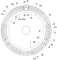
- FIGS. 1 A first embodiment of the present invention will be described with reference to FIGS.
- a damper device applied to a lockup clutch for a torque converter is exemplified.
- the lockup clutch will be explained.
- FIG. 1 the right side and the left side are referred to as “front side” and “rear side”, respectively.
- the damper device has a plurality of the same members, usually one member will be described.
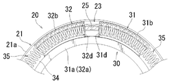
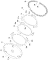
- the lock-up clutch 20 includes a disc-shaped clutch piston 21 provided in front of the rear side wall (the left side wall in FIG. 1) 11b of the torque converter cover 11 and the rear part of the turbine 13 (see FIG. 1). A predetermined number (three in this embodiment, one of which is shown in FIG. 1) of actuating members 25 projecting from the outer periphery of the outer periphery on the left side in FIG. And a damper device 30 provided between the turbine 13 and the turbine 13.
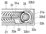
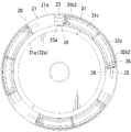
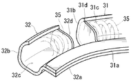
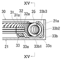
- each damper spring 35 is received in one of the receiving recesses 31c of the spring holding piece 31b of the first plate 31, and the other end is adjacent to the spring holding piece 31b in the circumferential direction. 2 is received in one of the receiving recesses 32c of the spring holding piece 32b of the plate 32 (see FIG. 6). Between the adjacent spring holding pieces 31b and 32b of the plates 31 and 32, a gap 34 of a predetermined angle is provided to allow relative rotation of the plates 31 and 32 (see FIG. 2). The spring holding pieces 31b and 32b of the plates 31 and 32 are formed so as to align with each other in the circumferential direction. The plates 31 and 32 are rotatable relative to the clutch piston 21 and the operation member 25 of the turbine 13, respectively.
- the “end portion” means a region near the end including the end.
- the other end of the damper spring 35 is received in the accommodating recess 32 c of the spring holding piece 32 b of the second plate 32.
- the end portions received in the accommodating recesses 31c and 32c are referred to as “first end portion” and “second end portion”, respectively.
- the spring seat 36 is in contact with the engaging member 23 and the operating member 25 with the elasticity of the damper spring 35.
Landscapes
- Engineering & Computer Science (AREA)
- General Engineering & Computer Science (AREA)
- Mechanical Engineering (AREA)
- Physics & Mathematics (AREA)
- Acoustics & Sound (AREA)
- Aviation & Aerospace Engineering (AREA)
- Mechanical Operated Clutches (AREA)
Abstract
L'invention porte sur un dispositif d'amortisseur (30) comportant un élément d'actionnement (25), un piston d'embrayage (21) capable de tourner par rapport à l'élément d'actionnement (25), au moins un ressort d'amortisseur (35) comprimé par une rotation relative de l'élément d'actionnement (25) et du piston d'embrayage (21), et ayant des première et seconde extrémités, un premier élément tournant (31) capable de tourner par rapport à l'élément d'actionnement (25) et au piston d'embrayage (21), capable de se déplacer conjointement avec la première extrémité du ressort d'amortisseur (35), et ayant au moins une première cavité de réception (31c) pour recevoir la première extrémité du ressort d'amortisseur (35), et un second élément tournant (32) capable de tourner par rapport à l'élément d'actionnement (25) et au piston d'embrayage (21), capable de se déplacer conjointement avec la seconde extrémité du ressort d'amortisseur (35) et ayant au moins une seconde cavité de réception (32c) pour recevoir la seconde extrémité du ressort d'amortisseur (35).
Applications Claiming Priority (2)
| Application Number | Priority Date | Filing Date | Title |
|---|---|---|---|
| JP2008193365A JP5143658B2 (ja) | 2008-07-28 | 2008-07-28 | ダンパ装置及びダンパスプリング |
| JP2008-193365 | 2008-07-28 |
Publications (1)
| Publication Number | Publication Date |
|---|---|
| WO2010013541A1 true WO2010013541A1 (fr) | 2010-02-04 |
Family
ID=41610247
Family Applications (1)
| Application Number | Title | Priority Date | Filing Date |
|---|---|---|---|
| PCT/JP2009/060032 Ceased WO2010013541A1 (fr) | 2008-07-28 | 2009-06-02 | Dispositif d'amortisseur et ressort d'amortisseur |
Country Status (2)
| Country | Link |
|---|---|
| JP (1) | JP5143658B2 (fr) |
| WO (1) | WO2010013541A1 (fr) |
Cited By (2)
| Publication number | Priority date | Publication date | Assignee | Title |
|---|---|---|---|---|
| CN107407370A (zh) * | 2015-03-19 | 2017-11-28 | 株式会社艾科赛迪 | 动态减振装置及液力偶合器 |
| CN107407371A (zh) * | 2015-03-19 | 2017-11-28 | 株式会社艾科赛迪 | 动态减震装置及流体接头 |
Citations (5)
| Publication number | Priority date | Publication date | Assignee | Title |
|---|---|---|---|---|
| JPH06147294A (ja) * | 1992-11-10 | 1994-05-27 | Nsk Warner Kk | トルクコンバータ用ロックアップクラッチのダンパー装置 |
| JP2002195379A (ja) * | 2000-12-26 | 2002-07-10 | Valeo Unisia Transmission Kk | ロックアップダンパー装置 |
| JP2006037973A (ja) * | 2004-07-22 | 2006-02-09 | Aisin Aw Industries Co Ltd | トルクコンバータのロックアップダンパ装置 |
| JP2007292223A (ja) * | 2006-04-26 | 2007-11-08 | F C C:Kk | ロックアップクラッチ |
| JP2008144934A (ja) * | 2006-12-13 | 2008-06-26 | Aisin Aw Industries Co Ltd | トルクコンバータのロックアップダンパ装置 |
-
2008
- 2008-07-28 JP JP2008193365A patent/JP5143658B2/ja not_active Expired - Fee Related
-
2009
- 2009-06-02 WO PCT/JP2009/060032 patent/WO2010013541A1/fr not_active Ceased
Patent Citations (5)
| Publication number | Priority date | Publication date | Assignee | Title |
|---|---|---|---|---|
| JPH06147294A (ja) * | 1992-11-10 | 1994-05-27 | Nsk Warner Kk | トルクコンバータ用ロックアップクラッチのダンパー装置 |
| JP2002195379A (ja) * | 2000-12-26 | 2002-07-10 | Valeo Unisia Transmission Kk | ロックアップダンパー装置 |
| JP2006037973A (ja) * | 2004-07-22 | 2006-02-09 | Aisin Aw Industries Co Ltd | トルクコンバータのロックアップダンパ装置 |
| JP2007292223A (ja) * | 2006-04-26 | 2007-11-08 | F C C:Kk | ロックアップクラッチ |
| JP2008144934A (ja) * | 2006-12-13 | 2008-06-26 | Aisin Aw Industries Co Ltd | トルクコンバータのロックアップダンパ装置 |
Cited By (6)
| Publication number | Priority date | Publication date | Assignee | Title |
|---|---|---|---|---|
| CN107407370A (zh) * | 2015-03-19 | 2017-11-28 | 株式会社艾科赛迪 | 动态减振装置及液力偶合器 |
| CN107407371A (zh) * | 2015-03-19 | 2017-11-28 | 株式会社艾科赛迪 | 动态减震装置及流体接头 |
| CN107407370B (zh) * | 2015-03-19 | 2019-04-26 | 株式会社艾科赛迪 | 动态减振装置及液力偶合器 |
| CN107407371B (zh) * | 2015-03-19 | 2019-04-26 | 株式会社艾科赛迪 | 动态减震装置及流体接头 |
| US10422408B2 (en) | 2015-03-19 | 2019-09-24 | Exedy Corporation | Dynamic vibration absorbing device and fluid coupling |
| US10473184B2 (en) | 2015-03-19 | 2019-11-12 | Exedy Corporation | Dynamic vibration absorbing device and fluid coupling |
Also Published As
| Publication number | Publication date |
|---|---|
| JP2010031933A (ja) | 2010-02-12 |
| JP5143658B2 (ja) | 2013-02-13 |
Similar Documents
| Publication | Publication Date | Title |
|---|---|---|
| US7900762B2 (en) | Twin clutch device | |
| JP4048487B2 (ja) | ダンパ装置およびロックアップクラッチ装置 | |
| CN102822551B (zh) | 双离合器 | |
| JP4489822B2 (ja) | フライホイール組立体 | |
| US20090095589A1 (en) | Lockup device, and fluid-type torque transmission device equipped with same | |
| CN102089548A (zh) | 动力传递部件、减振机构及飞轮组件 | |
| JP2014202228A (ja) | トルクダンパ装置 | |
| US20140144284A1 (en) | Dual mass flywheel | |
| KR20100081314A (ko) | 1차 휠에 대한 웨브의 반경방향 이동을 제한하기 위한 수단을 포함하는 듀얼 댐핑 휠이 마련되어 있는 마찰 클러치 장치 | |
| CN110352312B (zh) | 变矩器 | |
| JP4558772B2 (ja) | トルクダンパ | |
| WO2010013541A1 (fr) | Dispositif d'amortisseur et ressort d'amortisseur | |
| US6866129B2 (en) | Lockup device for fluid-type torque transmission device | |
| JP5388628B2 (ja) | ダンパー機構 | |
| JP4451912B2 (ja) | ダンパー機構 | |
| US6837347B2 (en) | Lockup device for fluid-type torque transmission device | |
| JP4512654B2 (ja) | ダンパー機構 | |
| KR20180036423A (ko) | 차량용 토크 컨버터 | |
| JP7429661B2 (ja) | トルクコンバータ | |
| JP2007132522A (ja) | 流体式トルク伝達装置のロックアップ装置 | |
| KR20140076315A (ko) | 차량용 토크 컨버터 | |
| JP5256160B2 (ja) | ダンパ装置及び動力伝達装置 | |
| JP2005282651A (ja) | 捩り振動低減装置 | |
| JP2010031885A (ja) | 動力伝達部品およびそれを備えたダンパー機構 | |
| JP2018096449A (ja) | ダンパ装置 |
Legal Events
| Date | Code | Title | Description |
|---|---|---|---|
| 121 | Ep: the epo has been informed by wipo that ep was designated in this application |
Ref document number: 09802786 Country of ref document: EP Kind code of ref document: A1 |
|
| NENP | Non-entry into the national phase |
Ref country code: DE |
|
| 122 | Ep: pct application non-entry in european phase |
Ref document number: 09802786 Country of ref document: EP Kind code of ref document: A1 |