WO2010016609A1 - 旋盤加工用部材 - Google Patents
旋盤加工用部材 Download PDFInfo
- Publication number
- WO2010016609A1 WO2010016609A1 PCT/JP2009/064141 JP2009064141W WO2010016609A1 WO 2010016609 A1 WO2010016609 A1 WO 2010016609A1 JP 2009064141 W JP2009064141 W JP 2009064141W WO 2010016609 A1 WO2010016609 A1 WO 2010016609A1
- Authority
- WO
- WIPO (PCT)
- Prior art keywords
- lathe
- alloy
- core
- copper
- noble metal
- Prior art date
- Legal status (The legal status is an assumption and is not a legal conclusion. Google has not performed a legal analysis and makes no representation as to the accuracy of the status listed.)
- Ceased
Links
Images




Classifications
-
- B—PERFORMING OPERATIONS; TRANSPORTING
- B23—MACHINE TOOLS; METAL-WORKING NOT OTHERWISE PROVIDED FOR
- B23B—TURNING; BORING
- B23B1/00—Methods for turning or working essentially requiring the use of turning-machines; Use of auxiliary equipment in connection with such methods
-
- B—PERFORMING OPERATIONS; TRANSPORTING
- B21—MECHANICAL METAL-WORKING WITHOUT ESSENTIALLY REMOVING MATERIAL; PUNCHING METAL
- B21C—MANUFACTURE OF METAL SHEETS, WIRE, RODS, TUBES, PROFILES OR LIKE SEMI-MANUFACTURED PRODUCTS OTHERWISE THAN BY ROLLING; AUXILIARY OPERATIONS USED IN CONNECTION WITH METAL-WORKING WITHOUT ESSENTIALLY REMOVING MATERIAL
- B21C1/00—Manufacture of metal sheets, wire, rods, tubes or like semi-manufactured products by drawing
-
- B—PERFORMING OPERATIONS; TRANSPORTING
- B23—MACHINE TOOLS; METAL-WORKING NOT OTHERWISE PROVIDED FOR
- B23B—TURNING; BORING
- B23B5/00—Turning-machines or devices specially adapted for particular work; Accessories specially adapted therefor
-
- B—PERFORMING OPERATIONS; TRANSPORTING
- B23—MACHINE TOOLS; METAL-WORKING NOT OTHERWISE PROVIDED FOR
- B23Q—DETAILS, COMPONENTS, OR ACCESSORIES FOR MACHINE TOOLS, e.g. ARRANGEMENTS FOR COPYING OR CONTROLLING; MACHINE TOOLS IN GENERAL CHARACTERISED BY THE CONSTRUCTION OF PARTICULAR DETAILS OR COMPONENTS; COMBINATIONS OR ASSOCIATIONS OF METAL-WORKING MACHINES, NOT DIRECTED TO A PARTICULAR RESULT
- B23Q3/00—Devices holding, supporting, or positioning work or tools, of a kind normally removable from the machine
- B23Q3/02—Devices holding, supporting, or positioning work or tools, of a kind normally removable from the machine for mounting on a work-table, tool-slide, or analogous part
- B23Q3/06—Work-clamping means
- B23Q3/062—Work-clamping means adapted for holding workpieces having a special form or being made from a special material
- B23Q3/064—Work-clamping means adapted for holding workpieces having a special form or being made from a special material for holding elongated workpieces, e.g. pipes, bars or profiles
-
- B—PERFORMING OPERATIONS; TRANSPORTING
- B23—MACHINE TOOLS; METAL-WORKING NOT OTHERWISE PROVIDED FOR
- B23Q—DETAILS, COMPONENTS, OR ACCESSORIES FOR MACHINE TOOLS, e.g. ARRANGEMENTS FOR COPYING OR CONTROLLING; MACHINE TOOLS IN GENERAL CHARACTERISED BY THE CONSTRUCTION OF PARTICULAR DETAILS OR COMPONENTS; COMBINATIONS OR ASSOCIATIONS OF METAL-WORKING MACHINES, NOT DIRECTED TO A PARTICULAR RESULT
- B23Q3/00—Devices holding, supporting, or positioning work or tools, of a kind normally removable from the machine
- B23Q3/02—Devices holding, supporting, or positioning work or tools, of a kind normally removable from the machine for mounting on a work-table, tool-slide, or analogous part
- B23Q3/06—Work-clamping means
- B23Q3/062—Work-clamping means adapted for holding workpieces having a special form or being made from a special material
- B23Q3/065—Work-clamping means adapted for holding workpieces having a special form or being made from a special material for holding workpieces being specially deformable, e.g. made from thin-walled or elastic material
-
- B—PERFORMING OPERATIONS; TRANSPORTING
- B23—MACHINE TOOLS; METAL-WORKING NOT OTHERWISE PROVIDED FOR
- B23B—TURNING; BORING
- B23B2215/00—Details of workpieces
- B23B2215/64—Thin walled components
-
- B—PERFORMING OPERATIONS; TRANSPORTING
- B23—MACHINE TOOLS; METAL-WORKING NOT OTHERWISE PROVIDED FOR
- B23B—TURNING; BORING
- B23B2222/00—Materials of tools or workpieces composed of metals, alloys or metal matrices
- B23B2222/12—Brass
-
- B—PERFORMING OPERATIONS; TRANSPORTING
- B23—MACHINE TOOLS; METAL-WORKING NOT OTHERWISE PROVIDED FOR
- B23B—TURNING; BORING
- B23B2222/00—Materials of tools or workpieces composed of metals, alloys or metal matrices
- B23B2222/21—Copper
-
- B—PERFORMING OPERATIONS; TRANSPORTING
- B23—MACHINE TOOLS; METAL-WORKING NOT OTHERWISE PROVIDED FOR
- B23B—TURNING; BORING
- B23B2222/00—Materials of tools or workpieces composed of metals, alloys or metal matrices
- B23B2222/24—Gold
-
- B—PERFORMING OPERATIONS; TRANSPORTING
- B23—MACHINE TOOLS; METAL-WORKING NOT OTHERWISE PROVIDED FOR
- B23B—TURNING; BORING
- B23B2222/00—Materials of tools or workpieces composed of metals, alloys or metal matrices
- B23B2222/68—Palladium
-
- B—PERFORMING OPERATIONS; TRANSPORTING
- B23—MACHINE TOOLS; METAL-WORKING NOT OTHERWISE PROVIDED FOR
- B23B—TURNING; BORING
- B23B2222/00—Materials of tools or workpieces composed of metals, alloys or metal matrices
- B23B2222/72—Platinum
-
- B—PERFORMING OPERATIONS; TRANSPORTING
- B23—MACHINE TOOLS; METAL-WORKING NOT OTHERWISE PROVIDED FOR
- B23B—TURNING; BORING
- B23B2222/00—Materials of tools or workpieces composed of metals, alloys or metal matrices
- B23B2222/76—Silver
-
- Y—GENERAL TAGGING OF NEW TECHNOLOGICAL DEVELOPMENTS; GENERAL TAGGING OF CROSS-SECTIONAL TECHNOLOGIES SPANNING OVER SEVERAL SECTIONS OF THE IPC; TECHNICAL SUBJECTS COVERED BY FORMER USPC CROSS-REFERENCE ART COLLECTIONS [XRACs] AND DIGESTS
- Y10—TECHNICAL SUBJECTS COVERED BY FORMER USPC
- Y10T—TECHNICAL SUBJECTS COVERED BY FORMER US CLASSIFICATION
- Y10T428/00—Stock material or miscellaneous articles
- Y10T428/12—All metal or with adjacent metals
- Y10T428/12229—Intermediate article [e.g., blank, etc.]
- Y10T428/12236—Panel having nonrectangular perimeter
-
- Y—GENERAL TAGGING OF NEW TECHNOLOGICAL DEVELOPMENTS; GENERAL TAGGING OF CROSS-SECTIONAL TECHNOLOGIES SPANNING OVER SEVERAL SECTIONS OF THE IPC; TECHNICAL SUBJECTS COVERED BY FORMER USPC CROSS-REFERENCE ART COLLECTIONS [XRACs] AND DIGESTS
- Y10—TECHNICAL SUBJECTS COVERED BY FORMER USPC
- Y10T—TECHNICAL SUBJECTS COVERED BY FORMER US CLASSIFICATION
- Y10T428/00—Stock material or miscellaneous articles
- Y10T428/12—All metal or with adjacent metals
- Y10T428/12493—Composite; i.e., plural, adjacent, spatially distinct metal components [e.g., layers, joint, etc.]
- Y10T428/12771—Transition metal-base component
- Y10T428/12861—Group VIII or IB metal-base component
-
- Y—GENERAL TAGGING OF NEW TECHNOLOGICAL DEVELOPMENTS; GENERAL TAGGING OF CROSS-SECTIONAL TECHNOLOGIES SPANNING OVER SEVERAL SECTIONS OF THE IPC; TECHNICAL SUBJECTS COVERED BY FORMER USPC CROSS-REFERENCE ART COLLECTIONS [XRACs] AND DIGESTS
- Y10—TECHNICAL SUBJECTS COVERED BY FORMER USPC
- Y10T—TECHNICAL SUBJECTS COVERED BY FORMER US CLASSIFICATION
- Y10T428/00—Stock material or miscellaneous articles
- Y10T428/12—All metal or with adjacent metals
- Y10T428/12493—Composite; i.e., plural, adjacent, spatially distinct metal components [e.g., layers, joint, etc.]
- Y10T428/12771—Transition metal-base component
- Y10T428/12861—Group VIII or IB metal-base component
- Y10T428/12875—Platinum group metal-base component
Definitions
- the present invention relates to a lathe member that is attached to a lathe and performs lathe machining.
- the workpiece which is a lathe machining member
- the workpiece is attached and fixed to the chuck of the lathe, and then the desired shape is formed by cutting the workpiece using a tool or a drill.
- Forming Specifically, for example, when an axially symmetric member such as a screw is formed by lathe processing, it is common to apply a cylindrical workpiece made of a solid solid material (see, for example, Patent Document 1). ).
- the present invention has been made in view of the above, and it is possible to reduce the waste of such material and reduce the cost when a product made of a rare and expensive material is formed by lathe processing. It aims at providing the member for lathe processing.
- a lathe machining member is a lathe machining member that performs lathe machining by being attached to a lathe, and at least a part thereof is made of a noble metal alloy, A cylindrical core portion having a diameter larger than the maximum diameter of a shape to be obtained by lathe processing, and a hollow cylindrical outer peripheral portion made of a material different from the core portion, and the core portion includes the outer peripheral portion. It is characterized in that it is provided in the hollow portion of this without gaps.
- the core portion includes a hollow cylindrical outer core portion and an inner core portion provided in the hollow portion of the outer core portion without a gap.
- One of the outer core portion and the inner core portion is made of the noble metal alloy, and the other is made of a metal different from the noble metal alloy.
- the lathe machining member according to the present invention is characterized in that, in the above invention, the diameter of the inner core portion is smaller than the maximum diameter.
- the lathe processing member according to the present invention is characterized in that, in the above invention, the outer peripheral portion is made of an alloy material.
- the alloy material is one material selected from the group consisting of copper alloy, silver-copper alloy, brass, phosphor bronze, and beryllium copper.
- the lathe machining member according to the present invention is the above-described invention, wherein the alloy material is one material selected from the group consisting of free-cutting brass, free-cutting phosphor bronze, free-cutting white, and free-cutting beryllium copper. It is characterized by being.
- the lathe machining member according to the present invention is characterized in that, in the above invention, the outer peripheral portion is iron.
- FIG. 1 is a diagram showing a configuration of a lathe member according to Embodiment 1 of the present invention.
- 2 is a cross-sectional view taken along line AA in FIG.
- FIG. 3 is a diagram showing an outline of lathe machining using the lathe machining member according to Embodiment 1 of the present invention.
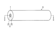
- FIG. 4 is a diagram showing a configuration of a lathe member according to Embodiment 2 of the present invention.
- 5 is a cross-sectional view taken along line BB in FIG.
- FIG. 6 is a diagram showing an outline of lathe machining using a lathe machining member according to Embodiment 2 of the present invention.
- FIG. 1 is a diagram showing a configuration of a lathe member according to Embodiment 1 of the present invention.
- 2 is a cross-sectional view taken along line AA in FIG.
- a lathe machining member 1 shown in FIGS. 1 and 2 is made of a hollow cylinder-shaped outer peripheral part 2 and a cylindrical core part 3 made of a material different from that of the outer peripheral part 2 and provided in the hollow part of the outer peripheral part 2 without a gap.
- the outer periphery 2 is made of an alloy material.
- the alloy material for example, one material selected from the group consisting of copper-white alloy, silver-copper alloy, brass, phosphor bronze, and beryllium copper can be applied.
- the alloy material for example, one material selected from the group consisting of free-cutting brass, free-cutting phosphor bronze, free-cutting white, and free-cutting beryllium copper (free-cutting material) can also be applied.
- materials for example, iron
- Core 3 is made of a noble metal alloy.
- this noble metal alloy for example, silver (Ag), palladium (Pd), gold (Au), platinum (Pt), zinc (Zn), copper (Cu), iron (Fe), nickel (Ni) are the main components.
- An alloy, an alloy containing palladium, silver, copper as a main component, an alloy containing silver, platinum, zinc, gold, copper as its main component, or the like can be used.
- the lathe member 1 is formed by drawing or drawing so that the diameter of the outer peripheral portion 2 and the diameter of the core portion 3 have a predetermined diameter ratio.
- FIG. 3 is a diagram showing an outline of lathe machining using the lathe machining member 1.
- the lathe machining member 1 is attached and fixed to the lathe chuck 4, and then the tool 5 is sent from the right to the left while rotating the chuck 4 at a predetermined rotational speed.
- the lathe member 1 is cut into a desired shape.
- the lathe member 1 may be further drawn or drawn.
- the maximum diameter R of the lathe member 1 after the cutting of the cutting tool 5 is smaller than the diameter r of the core 3 (R ⁇ r).
- the diameter r of the core portion 3 is determined to be larger than the maximum diameter R of the shape to be obtained by lathe processing, and the processed product is composed only of a noble metal alloy. It will be.
- FIG. 3 illustrates a case where the shape after shaving is cylindrical, but this is only an example. That is, in the first embodiment, the diameter r is determined so that the maximum diameter in the shape is smaller than the diameter r of the core portion 3 regardless of the shape after processing.
- FIG. 4 is a diagram showing a configuration of a lathe member according to Embodiment 2 of the present invention.
- 5 is a cross-sectional view taken along line BB in FIG.
- the lathe machining member 6 shown in FIG. 4 and FIG. 5 includes an outer peripheral portion 7 having a hollow cylindrical shape and a cylindrical core portion 8 provided in the hollow portion of the outer peripheral portion 7 without a gap.
- the outer peripheral part 7 consists of the same material as the outer peripheral part 2 in Embodiment 1.
- FIG. 1 is a diagram showing a configuration of a lathe member according to Embodiment 2 of the present invention.
- 5 is a cross-sectional view taken along line BB in FIG.
- the lathe machining member 6 shown in FIG. 4 and FIG. 5 includes an outer peripheral portion 7 having a hollow cylindrical shape and a cylindrical core portion 8 provided in the hollow portion of the outer peripheral portion 7 without a gap.
- the outer peripheral part 7 consists of the same material as the outer peripheral part 2 in Embodiment 1.
- the core portion 8 has a hollow cylindrical outer core portion 81 and an inner core portion 82 provided in the hollow portion of the outer core portion 81 without a gap.
- One of the outer core portion 81 and the inner core portion 82 is made of a noble metal alloy similar to the core portion 3 described above, and the other is made of a metal different from the noble metal alloy, such as copper or aluminum. What is necessary is just to determine the combination of the material of the outer core part 81 and the inner core part 82 according to the use of a processed product.
- FIG. 6 is a diagram showing an outline of lathe machining using the lathe machining member 6. Although not shown in FIG. 6, the left end portion of the lathe machining member 6 is fixed to the chuck 4 as in FIG. 3. For this reason, the lathe machining member 6 rotates as the chuck 4 rotates.
- such a material is wasted when a processed product made of a rare and expensive material such as a noble metal alloy is formed. It is possible to reduce the cost and the cost.
- the core portion 8 has the outer core portion 81 and the inner core portion 82 made of different metals (including noble metal alloys), so that it is optimal for the use of the processed product. Any combination of materials can be made.
- the core part instead of the core part having two layers of the outer core part and the inner core part, it is possible to have a multilayer structure of two or more layers made of different metals.
- the present invention is useful as a member for attaching to a lathe and performing lathe processing.
Landscapes
- Engineering & Computer Science (AREA)
- Mechanical Engineering (AREA)
- Turning (AREA)
Abstract
Description
図1は、本発明の実施の形態1に係る旋盤加工用部材の構成を示す図である。図2は、図1のA-A線断面図である。図1および図2に示す旋盤加工用部材1は、中空円柱状をなす外周部2と、外周部2と異なる材料からなり、外周部2の中空部に隙間なく設けられる円柱状の芯部3とを備える。
図4は、本発明の実施の形態2に係る旋盤加工用部材の構成を示す図である。図5は、図4のB-B線断面図である。図4および図5に示す旋盤加工用部材6は、中空円柱状をなす外周部7と、外周部7の中空部に隙間なく設けられる円柱状の芯部8とを備える。外周部7は、実施の形態1における外周部2と同様の材料からなる。
2、7 外周部
3、8 芯部
4 チャック
5 バイト
81 外芯部
82 内芯部
Claims (7)
- 旋盤に取り付けることによって旋盤加工を行う旋盤加工用部材であって、
少なくとも一部が貴金属合金からなり、旋盤加工によって得られるべき形状の最大径より大きい径を有する円柱状の芯部と、
前記芯部とは異なる材料からなる中空円柱状の外周部と、
を備え、
前記芯部は、前記外周部の中空部に隙間なく設けられることを特徴とする旋盤加工用部材。 - 前記芯部は、
中空円柱状の外芯部と、
前記外芯部の中空部に隙間なく設けられた内芯部と、
を有し、
前記外芯部および前記内芯部の一方が前記貴金属合金からなり、他方が前記貴金属合金と異なる金属からなることを特徴とする請求項1記載の旋盤加工用部材。 - 前記内芯部の径は前記最大径より小さいことを特徴とする請求項2記載の旋盤加工用部材。
- 前記外周部は、合金材からなることを特徴とする請求項1~3のいずれか一項記載の旋盤加工用部材。
- 前記合金材は、銅洋白合金、銀銅合金、黄銅、りん青銅、ベリリウム銅からなる群より選ばれる一の材料であることを特徴とする請求項4記載の旋盤加工用部材。
- 前記合金材は、快削黄銅、快削りん青銅、快削洋白、および快削ベリリウム銅からなる群より選ばれる一の材料であることを特徴とする請求項4記載の旋盤加工用部材。
- 前記外周部は、鉄であることを特徴とする請求項1~3のいずれか一項記載の旋盤加工用部材。
Priority Applications (4)
| Application Number | Priority Date | Filing Date | Title |
|---|---|---|---|
| US12/737,555 US9056355B2 (en) | 2008-08-08 | 2009-08-10 | Lathe machining member |
| CN2009801291355A CN102105246B (zh) | 2008-08-08 | 2009-08-10 | 车床加工用构件 |
| EP09805089.1A EP2311588A4 (en) | 2008-08-08 | 2009-08-10 | Member for lathe machining |
| JP2010523916A JP5228049B2 (ja) | 2008-08-08 | 2009-08-10 | 旋盤加工用部材 |
Applications Claiming Priority (2)
| Application Number | Priority Date | Filing Date | Title |
|---|---|---|---|
| JP2008206239 | 2008-08-08 | ||
| JP2008-206239 | 2008-08-08 |
Publications (1)
| Publication Number | Publication Date |
|---|---|
| WO2010016609A1 true WO2010016609A1 (ja) | 2010-02-11 |
Family
ID=41663817
Family Applications (1)
| Application Number | Title | Priority Date | Filing Date |
|---|---|---|---|
| PCT/JP2009/064141 Ceased WO2010016609A1 (ja) | 2008-08-08 | 2009-08-10 | 旋盤加工用部材 |
Country Status (6)
| Country | Link |
|---|---|
| US (1) | US9056355B2 (ja) |
| EP (1) | EP2311588A4 (ja) |
| JP (1) | JP5228049B2 (ja) |
| KR (1) | KR20110025979A (ja) |
| CN (1) | CN102105246B (ja) |
| WO (1) | WO2010016609A1 (ja) |
Cited By (1)
| Publication number | Priority date | Publication date | Assignee | Title |
|---|---|---|---|---|
| WO2012005234A1 (ja) * | 2010-07-05 | 2012-01-12 | 日本発條株式会社 | 旋盤加工用部材、針状部材およびコンタクトプローブ |
Families Citing this family (2)
| Publication number | Priority date | Publication date | Assignee | Title |
|---|---|---|---|---|
| TWI496652B (zh) * | 2009-07-09 | 2015-08-21 | Citizen Holdings Co Ltd | Processing materials and holding institutions |
| EP4292734A4 (en) * | 2021-02-09 | 2025-01-22 | Nanshin Co., Ltd | Semi-finished pipe, method for producing semi-finished pipe, pipe, and method for producing pipe |
Citations (3)
| Publication number | Priority date | Publication date | Assignee | Title |
|---|---|---|---|---|
| JPH0650391A (ja) * | 1992-08-03 | 1994-02-22 | Matsuzawa Seisakusho:Kk | 継ぎ目無し金属製ベルト及びその製造方法 |
| JPH07275924A (ja) * | 1994-03-31 | 1995-10-24 | Tokin Corp | TiPd系合金の伸線方法 |
| JP2003291002A (ja) | 2002-03-29 | 2003-10-14 | Ndc Co Ltd | 旋盤用多目的治具 |
Family Cites Families (13)
| Publication number | Priority date | Publication date | Assignee | Title |
|---|---|---|---|---|
| US2196303A (en) * | 1939-02-21 | 1940-04-09 | Mallory & Co Inc P R | Silver copper alloy |
| US2527599A (en) * | 1946-11-30 | 1950-10-31 | Int Standard Electric Corp | Facsimile device |
| US2930115A (en) * | 1956-10-25 | 1960-03-29 | Sr Otto Dietzsch | Method of producing a modular body for controlled mixing or emission of a plurality of fluids |
| US2872899A (en) * | 1957-12-02 | 1959-02-10 | Trespalacios Basilio | Writing instrument |
| DE2253690B2 (de) * | 1972-11-02 | 1974-08-15 | Vereinigte Deutsche Metallwerke Ag, 6000 Frankfurt | Messinglegierung mit verbesserter Zerspannbarkeit |
| JPS5911386B2 (ja) * | 1981-11-09 | 1984-03-15 | 株式会社中島銅工所 | 半田用チツプの製造方法 |
| JPH05309538A (ja) | 1992-05-11 | 1993-11-22 | Seiko Seiki Co Ltd | パイプの加工方法 |
| JPH09267222A (ja) * | 1996-04-01 | 1997-10-14 | Idemitsu Petrochem Co Ltd | シームレス金属ベルトの製造方法 |
| US6386423B1 (en) * | 1997-02-10 | 2002-05-14 | Delaware Capital Formation, Inc. | Soldering iron tips |
| JP4139520B2 (ja) | 1999-06-08 | 2008-08-27 | Dowaホールディングス株式会社 | 工作機械用のワーク保持治具及び加工方法 |
| CN2485066Y (zh) * | 2001-03-05 | 2002-04-10 | 华南理工大学 | 一种碳钢芯不锈钢复合棒材 |
| US7687156B2 (en) * | 2005-08-18 | 2010-03-30 | Tdy Industries, Inc. | Composite cutting inserts and methods of making the same |
| CN100496786C (zh) * | 2007-09-07 | 2009-06-10 | 宝鸡市亚钛新金属有限公司 | 一种钛基复合棒材的制造方法 |
-
2009
- 2009-08-10 KR KR1020117001622A patent/KR20110025979A/ko not_active Ceased
- 2009-08-10 CN CN2009801291355A patent/CN102105246B/zh not_active Expired - Fee Related
- 2009-08-10 WO PCT/JP2009/064141 patent/WO2010016609A1/ja not_active Ceased
- 2009-08-10 US US12/737,555 patent/US9056355B2/en active Active
- 2009-08-10 EP EP09805089.1A patent/EP2311588A4/en not_active Withdrawn
- 2009-08-10 JP JP2010523916A patent/JP5228049B2/ja active Active
Patent Citations (3)
| Publication number | Priority date | Publication date | Assignee | Title |
|---|---|---|---|---|
| JPH0650391A (ja) * | 1992-08-03 | 1994-02-22 | Matsuzawa Seisakusho:Kk | 継ぎ目無し金属製ベルト及びその製造方法 |
| JPH07275924A (ja) * | 1994-03-31 | 1995-10-24 | Tokin Corp | TiPd系合金の伸線方法 |
| JP2003291002A (ja) | 2002-03-29 | 2003-10-14 | Ndc Co Ltd | 旋盤用多目的治具 |
Non-Patent Citations (1)
| Title |
|---|
| See also references of EP2311588A4 * |
Cited By (1)
| Publication number | Priority date | Publication date | Assignee | Title |
|---|---|---|---|---|
| WO2012005234A1 (ja) * | 2010-07-05 | 2012-01-12 | 日本発條株式会社 | 旋盤加工用部材、針状部材およびコンタクトプローブ |
Also Published As
| Publication number | Publication date |
|---|---|
| EP2311588A1 (en) | 2011-04-20 |
| CN102105246B (zh) | 2013-12-25 |
| KR20110025979A (ko) | 2011-03-14 |
| US20110123827A1 (en) | 2011-05-26 |
| JPWO2010016609A1 (ja) | 2012-01-26 |
| US9056355B2 (en) | 2015-06-16 |
| JP5228049B2 (ja) | 2013-07-03 |
| EP2311588A4 (en) | 2018-03-14 |
| CN102105246A (zh) | 2011-06-22 |
Similar Documents
| Publication | Publication Date | Title |
|---|---|---|
| TWI225810B (en) | Wire electrode for spark erosion gutting | |
| JP5228049B2 (ja) | 旋盤加工用部材 | |
| JP2000308924A (ja) | ワイヤ電極、およびその製造方法 | |
| KR20060041991A (ko) | 와이어 방전 가공용전극선 | |
| CN107000058B (zh) | 烧结部件的制造方法以及烧结部件 | |
| JPS59175912A (ja) | 超硬ドリル | |
| JP4416113B2 (ja) | 異形線伸線用ダイヤモンドダイス | |
| CN104400159A (zh) | 一种高效多层复合电极丝 | |
| JP4285324B2 (ja) | ワイヤ放電加工用電極線及びそれを用いて製造した放電加工物 | |
| JP3087552B2 (ja) | 放電加工用電極線 | |
| JP2004330352A (ja) | ワイヤ放電加工用電極線及びそれを用いた表面改質方法 | |
| TWI442055B (zh) | 車床加工用構件、針狀構件及接觸探針 | |
| JP2020059043A (ja) | 非晶質合金片の製造方法 | |
| JP3153247U (ja) | 刃物保持冶具 | |
| JP2011147942A (ja) | ロッド部材 | |
| JPH0881723A (ja) | クロム銅および溶接機用コンタクトチップ・キャップチップ | |
| JP2005205557A (ja) | タップ | |
| CN206597949U (zh) | 一种pcb板成型用铣削装置 | |
| JPH11347847A (ja) | ワイヤ放電加工用電極線 | |
| JPS59118849A (ja) | ワイヤカツト放電加工用電極材 | |
| JPH06106420A (ja) | 放電加工用ワイヤ電極線 | |
| JPH0647552A (ja) | 溶接用チップの製造方法 | |
| JP2008062325A (ja) | ワイヤ放電加工用電極線 | |
| CN101249576A (zh) | 一种用于加工齿圈的刀具 | |
| JPH0366524A (ja) | 放電加工用電極線 |
Legal Events
| Date | Code | Title | Description |
|---|---|---|---|
| WWE | Wipo information: entry into national phase |
Ref document number: 200980129135.5 Country of ref document: CN |
|
| 121 | Ep: the epo has been informed by wipo that ep was designated in this application |
Ref document number: 09805089 Country of ref document: EP Kind code of ref document: A1 |
|
| WWE | Wipo information: entry into national phase |
Ref document number: 2010523916 Country of ref document: JP |
|
| ENP | Entry into the national phase |
Ref document number: 20117001622 Country of ref document: KR Kind code of ref document: A |
|
| WWE | Wipo information: entry into national phase |
Ref document number: 12737555 Country of ref document: US |
|
| WWE | Wipo information: entry into national phase |
Ref document number: 2009805089 Country of ref document: EP |
|
| NENP | Non-entry into the national phase |
Ref country code: DE |