WO2010027079A1 - 撮像装置および方法、並びにプログラム - Google Patents
撮像装置および方法、並びにプログラム Download PDFInfo
- Publication number
- WO2010027079A1 WO2010027079A1 PCT/JP2009/065625 JP2009065625W WO2010027079A1 WO 2010027079 A1 WO2010027079 A1 WO 2010027079A1 JP 2009065625 W JP2009065625 W JP 2009065625W WO 2010027079 A1 WO2010027079 A1 WO 2010027079A1
- Authority
- WO
- WIPO (PCT)
- Prior art keywords
- image
- unit
- imaging
- composition
- subject
- Prior art date
- Legal status (The legal status is an assumption and is not a legal conclusion. Google has not performed a legal analysis and makes no representation as to the accuracy of the status listed.)
- Ceased
Links
Images












Classifications
-
- H—ELECTRICITY
- H04—ELECTRIC COMMUNICATION TECHNIQUE
- H04N—PICTORIAL COMMUNICATION, e.g. TELEVISION
- H04N5/00—Details of television systems
- H04N5/222—Studio circuitry; Studio devices; Studio equipment
- H04N5/262—Studio circuits, e.g. for mixing, switching-over, change of character of image, other special effects ; Cameras specially adapted for the electronic generation of special effects
- H04N5/265—Mixing
-
- H—ELECTRICITY
- H04—ELECTRIC COMMUNICATION TECHNIQUE
- H04N—PICTORIAL COMMUNICATION, e.g. TELEVISION
- H04N23/00—Cameras or camera modules comprising electronic image sensors; Control thereof
- H04N23/45—Cameras or camera modules comprising electronic image sensors; Control thereof for generating image signals from two or more image sensors being of different type or operating in different modes, e.g. with a CMOS sensor for moving images in combination with a charge-coupled device [CCD] for still images
-
- G—PHYSICS
- G06—COMPUTING OR CALCULATING; COUNTING
- G06T—IMAGE DATA PROCESSING OR GENERATION, IN GENERAL
- G06T3/00—Geometric image transformations in the plane of the image
- G06T3/40—Scaling of whole images or parts thereof, e.g. expanding or contracting
-
- H—ELECTRICITY
- H04—ELECTRIC COMMUNICATION TECHNIQUE
- H04N—PICTORIAL COMMUNICATION, e.g. TELEVISION
- H04N23/00—Cameras or camera modules comprising electronic image sensors; Control thereof
- H04N23/60—Control of cameras or camera modules
- H04N23/61—Control of cameras or camera modules based on recognised objects
-
- H—ELECTRICITY
- H04—ELECTRIC COMMUNICATION TECHNIQUE
- H04N—PICTORIAL COMMUNICATION, e.g. TELEVISION
- H04N23/00—Cameras or camera modules comprising electronic image sensors; Control thereof
- H04N23/60—Control of cameras or camera modules
- H04N23/61—Control of cameras or camera modules based on recognised objects
- H04N23/611—Control of cameras or camera modules based on recognised objects where the recognised objects include parts of the human body
-
- H—ELECTRICITY
- H04—ELECTRIC COMMUNICATION TECHNIQUE
- H04N—PICTORIAL COMMUNICATION, e.g. TELEVISION
- H04N23/00—Cameras or camera modules comprising electronic image sensors; Control thereof
- H04N23/60—Control of cameras or camera modules
- H04N23/63—Control of cameras or camera modules by using electronic viewfinders
-
- H—ELECTRICITY
- H04—ELECTRIC COMMUNICATION TECHNIQUE
- H04N—PICTORIAL COMMUNICATION, e.g. TELEVISION
- H04N23/00—Cameras or camera modules comprising electronic image sensors; Control thereof
- H04N23/95—Computational photography systems, e.g. light-field imaging systems
- H04N23/951—Computational photography systems, e.g. light-field imaging systems by using two or more images to influence resolution, frame rate or aspect ratio
-
- H—ELECTRICITY
- H04—ELECTRIC COMMUNICATION TECHNIQUE
- H04N—PICTORIAL COMMUNICATION, e.g. TELEVISION
- H04N7/00—Television systems
- H04N7/18—Closed-circuit television [CCTV] systems, i.e. systems in which the video signal is not broadcast
-
- H—ELECTRICITY
- H04—ELECTRIC COMMUNICATION TECHNIQUE
- H04N—PICTORIAL COMMUNICATION, e.g. TELEVISION
- H04N2101/00—Still video cameras
Definitions
- the present invention relates to an imaging apparatus and method, and a program, and more particularly, to an imaging apparatus and method, and a program that make it possible to easily confirm a composition.
- Some imaging devices such as digital cameras, include two imaging systems.
- an imaging device provided with a front camera that images the front of the user and a rear camera that images the rear has been proposed (see, for example, Patent Document 1).
- the user can not simultaneously capture one object with two imaging systems.
- the present invention has been made in view of such a situation, and makes it possible to more easily confirm the composition.
- An imaging apparatus is a composition that combines a first image obtained by imaging a subject, and a second image different from the first image and an imaging range such that the position of the subject matches. And means for displaying the first image and the second image combined by the combining means.
- the image pickup device is an image having a size different from that of the first image from an image pickup means for receiving the light from the optical system to pick up the first image of the subject, and the first image.
- an extracting unit that extracts a second image including the subject having a high degree of attention, and the combining unit is configured to use the extracting unit so that the position of the subject matches the first image.
- the display unit is configured to combine the extracted second image, and the display unit is configured to display the second image in a portion corresponding to a predetermined region having the same size as the second image in a display region capable of displaying the entire first image.
- the first image can be displayed and the second image combined with the first image can be displayed.
- the second image can be emphasized and displayed in the display area on the display means.
- the display area is an area where the entire first image is displayed when the imaging mode is a standard mode for capturing an image having an aspect ratio of 4: 3, and the predetermined area in the display area is
- the imaging mode may be an area in which a part of the first image is displayed when the imaging mode is a panoramic mode for capturing an image with an aspect ratio of 16: 9.
- a cutting-out unit that cuts out the first image of the predetermined area, the first image cut out by the cutting-out unit, and the second image extracted by the extraction unit
- recording means for recording the information.
- the combining means combines the first image cut out by the cutting means with the second image extracted by the extraction means, and the recording means combines the first image and the second image.
- the first image and the second image can be recorded.
- the imaging device receives light from a first optical system, receives a first imaging unit for capturing the first image of the subject, and receives light from a second optical system. Adjusting the image quality of the second image to be different from the image quality of the first image; and a second imaging unit for capturing a second image of the subject different in angle of view from the first image
- a first image quality adjustment unit is further provided, and the combining unit is configured to match the position of the subject with the second image whose image quality has been adjusted by the first image quality adjustment unit. Can be combined.
- the image pickup apparatus includes an object detection unit that detects an object in the second image, and an image quality of a region of the object in the second image detected by the object detection unit.
- a second image quality adjustment unit for adjusting the image quality differently from the image quality of the first image, and the combining unit includes the first image and the first image so that the position of the subject matches the second image.
- An object image of the area of the object in the second image whose image quality has been adjusted by the second image quality adjustment means can be synthesized.
- the object detection means may detect the object with motion in the second image.
- the object detection means can detect a human face in the second image.
- the composition of the angle of view different from the angle of view of the first image based on the composition analysis means for analyzing the composition of the second image and the composition analyzed by the composition analysis means
- the image processing apparatus further comprises composition extracting means for extracting from the second image, and the combining means includes the first image and the composition extracting means so that the position of the subject coincides with the second image. It is possible to combine extracted images of the extracted composition.
- the second image pickup means can receive the light from the second optical system to pick up the second image having a wider angle of view than the first image of the subject.
- a distortion correction unit that corrects the distortion of the second image, and an optical axis of the second optical system aligned with an optical axis of the first optical system
- the second image Optical axis correction means for determining the position of the first image to be synthesized.
- the first image quality adjustment means may adjust the level of the color signal of the second image to be lower than the level of the color signal of the first image.
- the imaging device may further include second image quality adjustment means for adjusting the image quality of the first image to be different from the image quality of the second image.
- the second image quality adjustment means may adjust the level of the color signal of the first image to be higher than the level of the color signal of the second image.
- An imaging method includes a synthesizing step of synthesizing a first image obtained by imaging a subject, a second image different from the first image and an imaging range, and the synthesizing step. Displaying the first image and the second image.
- the program according to one aspect of the present invention is synthesized by the process of synthesizing the first image obtained by imaging the subject, the second image different from the first image and the area of imaging, and the process of the synthesis step. And causing a computer to execute a process including a display step of displaying the first image and the second image.
- a first image obtained by imaging a subject, and a first image and a second image different in imaging range are synthesized, and the synthesized first image and second image are generated. Is displayed.
- FIG. 1 is a view showing an example of the appearance of a digital camera as an embodiment of an imaging device to which the present invention is applied. It is a figure which shows the example of a display of the captured image which a digital camera images. It is a block diagram showing an example of functional composition of a digital camera. It is a block diagram showing an example of composition of an image processing part. It is a block diagram showing an example of composition of an image processing part. It is a block diagram showing an example of composition of an image processing part. It is a block diagram showing an example of composition of an image processing part. It is a block diagram showing an example of composition of an image processing part. It is a block diagram showing an example of composition of an image processing part. It is a block diagram showing an example of composition of an image processing part. It is a block diagram showing an example of composition of an image processing part. It is a block diagram showing an example of composition of an image processing part. It is a block diagram showing an example of composition of an image processing part.
- FIG. 1 shows an example of the appearance of a digital camera as an embodiment of an imaging apparatus to which the present invention is applied.
- the digital camera 11 of FIG. 1 includes two optical systems of a main lens 31 and a sub lens 32.
- the main lens 31 is a so-called standard lens.
- the sub lens 32 is a wide angle lens (for example, a fisheye lens etc.), and the angle of view thereof is sufficiently wide as compared with the main lens 31.
- FIG. 2 shows a display example of a captured image captured by the digital camera 11.
- the digital camera 11 performs correction processing such as distortion correction on an image (sub-image) captured through the sub-lens 32 to perform predetermined image processing (blurring the image, luminance, Apply saturation etc.). Further, the digital camera 11 performs predetermined image processing (for example, raising the luminance and saturation) on an image (main image) captured through the main lens 31.
- the digital camera 11 adjusts the position and angle of view of the main image and the sub image, and an image (synthesized image) obtained by combining the main image and the sub image is provided on the back of the digital camera 11. For example, as shown in FIG. The user can recognize the angle of view to be imaged by confirming the display content of the display unit (not shown).
- the synthesized image shown in FIG. 2 is synthesized such that the sub-image (wide-angle image) subjected to the predetermined correction and the image processing and the main image (standard image) match the position of the subject in each image. ing.
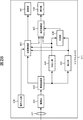
- the digital camera 11 of FIG. 3 includes a main lens 31, a sub lens 32, an imaging unit 51, a distortion correction unit 52, an optical axis correction unit 53, an image processing unit 54, an imaging unit 55, an image processing unit 56, a combining unit 57, and A display unit 58 is provided.
- the main lens 31 and the sub lens 32 are the same as those described with reference to FIG.
- the imaging unit 51 is configured to include an imaging element and an A / D (Analog / Digital) conversion unit.
- the imaging unit 51 receives light from the sub lens 32 and performs photoelectric conversion to image a subject, and A / D converts the obtained analog image signal.
- the imaging unit 51 supplies the distortion correction unit 52 with digital image data (wide-angle image) obtained as a result of A / D conversion.
- the distortion correction unit 52 corrects the distortion of the sub lens 32 in the wide-angle image (sub image) from the imaging unit 51, and supplies the corrected sub image to the optical axis correction unit 53.
- the optical axis correction unit 53 aligns the optical axis of the sub lens 32 with the optical axis of the main lens 31, and determines the position of the main image to be synthesized with the sub image in the sub image from the distortion correction unit 52.
- the sub image is supplied to the image processing unit 54 together with the position information indicating.
- the image processing unit 54 performs predetermined image processing (adjustment of picture, brightness, color saturation, color tone, sharpness, etc.) on the sub image from the optical axis correction unit 53 so as to lower the image quality than the main image. Together with position information, and supplies it to the combining unit 57.
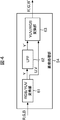
- FIG. 4 is a first configuration example, and illustrates a configuration example of the image processing unit 54 that performs blurring processing on a sub image.
- the image processing unit 54 in FIG. 4 includes an RGB / YUV conversion unit 61, an LPF (Low Pass Filter) 62, and a YUV / RGB conversion unit 63.
- the RGB / YUV conversion unit 61 converts the RGB signal as the sub image supplied from the optical axis correction unit 53 into a YUV signal based on the following equation (1).
- the RGB / YUV conversion unit 61 supplies the Y signal (luminance signal) of the converted YUV signal to the LPF 62 and supplies the U and V signals (color difference signal) to the YUV / RGB conversion unit 63.
- the LPF 62 smoothes the Y signal supplied from the RGB / YUV conversion unit 61 to remove high frequency components, and supplies the high frequency component to the YUV / RGB conversion unit 63.
- the YUV / RGB converter 63 converts the Y signal (Y ′) from the LPF 62 and the U and V signals from the RGB / YUV converter 61 into RGB signals based on the following equation (2).
- the YUV / RGB converter 63 supplies the converted RGB signals (R ′, G ′, B ′) as a sub image to the synthesizer 57.
- the image processing unit 54 can perform blurring processing on the sub image.
- FIG. 5 shows a second configuration example, and shows a configuration example of the image processing unit 54 for reducing the saturation of the sub image.
- the image processing unit 54 in FIG. 5 includes an RGB / HSV conversion unit 71, a saturation adjustment unit (S adjustment unit) 72, and an HSV / RGB conversion unit 73.
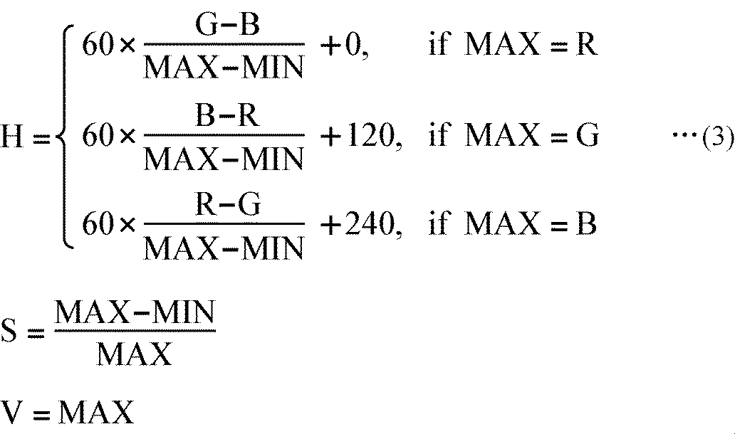
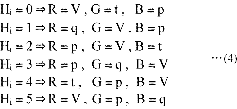
- the RGB / HSV conversion unit 71 converts the RGB signal as the sub image supplied from the optical axis correction unit 53 into an HSV signal based on the following equation (3).
- the RGB / HSV conversion unit 71 supplies the S signal (saturation signal) of the converted HSV signal to the S adjustment unit 72, and converts the H signal (hue signal) and the V signal (brightness signal) into an HSV / RGB conversion Supply to the unit 73.
- the S adjustment unit 72 multiplies the S signal supplied from the RGB / HSV conversion unit 71 by a predetermined coefficient ⁇ (0 ⁇ ⁇ 1) and supplies the product to the HSV / RGB conversion unit 73.
- the HSV / RGB converter 73 supplies the converted RGB signals (R ′, G ′, B ′) as a sub-image to the synthesizer 57.
- the image processing unit 54 can reduce the saturation of the sub image.
- FIG. 6 shows a third configuration example, and shows a configuration example of the image processing unit 54 for reducing the lightness of the sub image.
- the image processing unit 54 in FIG. 6 includes an RGB / HSV conversion unit 81, a lightness adjustment unit (V adjustment unit) 82, and an HSV / RGB conversion unit 83.
- the RGB / HSV conversion unit 81 converts the RGB signal as the sub image supplied from the optical axis correction unit 53 into an HSV signal based on the above equation (3), and converts the V signal among the converted HSV signals. While supplying to the V adjustment unit 82, the H signal and the S signal are supplied to the HSV / RGB conversion unit 83.
- the V adjustment unit 82 multiplies the V signal supplied from the RGB / HSV conversion unit 81 by a predetermined coefficient ⁇ (0 ⁇ ⁇ 1) and supplies the product to the HSV / RGB conversion unit 83.
- the converted and converted RGB signals (R ′, G ′, B ′) are supplied to the combining unit 57 as a sub image.
- the image processing unit 54 can lower the lightness of the sub image.
- the image quality of the sub image can be lower than the image quality of the main image.
- the imaging unit 55 is configured to include an imaging element and an A / D conversion unit.
- the imaging unit 55 receives light from the main lens 31 and performs photoelectric conversion to image an object, and A / D converts the obtained analog image signal.
- the imaging unit 55 supplies the digital image data (standard image) obtained as a result of A / D conversion to the image processing unit 56.
- the image processing unit 56 performs predetermined image processing on the main image (standard image) from the imaging unit 55 so as to improve the image quality more than the sub image (adjustment of picture, brightness, color density, color tone, sharpness, etc. ) And supply to the synthesis unit 57.
- FIG. 7 shows a first configuration example, and shows a configuration example of the image processing unit 56 which performs an emphasizing process for emphasizing the shape and the outline of the main image.
- the image processing unit 56 in FIG. 7 includes an RGB / YUV conversion unit 91, an HPF (High Pass Filter) 92, an amplifier 93, an adder 94, and a YUV / RGB conversion unit 95.
- RGB / YUV conversion unit 91 an RGB / YUV conversion unit 91
- HPF High Pass Filter
- amplifier 93 an amplifier 93
- adder 94 an adder 94
- YUV / RGB conversion unit 95 a YUV / RGB conversion unit 95.
- the RGB / YUV conversion unit 91 converts the RGB signal as the main image from the imaging unit 55 into a YUV signal based on the above equation (1), and converts the Y signal among the converted YUV signals into an HPF 92 and an adder. While being supplied to 94, the U and V signals are supplied to the YUV / RGB converter 95.
- the HPF 92 takes out the high frequency component of the Y signal supplied from the RGB / YUV conversion unit 91, and supplies the high frequency component to the amplifier 93.
- the amplifier 93 amplifies the high frequency component of the Y signal from the HPF 92 to A (A> 1) times and supplies the amplified signal to the adder 94.
- the adder 94 adds the high frequency component of the amplified Y signal from the amplifier 93 to the Y signal from the RGB / YUV converter 91, and supplies the result to the YUV / RGB converter 95.
- the YUV / RGB converter 95 converts the Y signal (Y ′) from the adder 94 and the U and V signals from the RGB / YUV converter 91 into RGB signals based on the above equation (2).
- the converted RGB signals (R ′, G ′, B ′) are supplied to the combining unit 57 as a main image.
- the image processing unit 56 can perform the enhancement process on the main image.
- FIG. 8 shows a second configuration example, and shows a configuration example of the image processing unit 56 for increasing the saturation of the main image.
- the image processing unit 56 in FIG. 8 includes an RGB / HSV conversion unit 101, a saturation adjustment unit (S adjustment unit) 102, and an HSV / RGB conversion unit 103.
- the RGB / HSV conversion unit 101 and the HSV / RGB conversion unit 103 have the same functions as the RGB / HSV conversion unit 71 and the HSV / RGB conversion unit 73 provided in the image processing unit 54 in FIG. The description is omitted.
- the S adjustment unit 102 multiplies the S signal supplied from the RGB / HSV conversion unit 101 by a predetermined coefficient ⁇ ( ⁇ ⁇ 1) and supplies the result to the HSV / RGB conversion unit 103.
- the image processing unit 56 can increase the saturation of the main image.
- FIG. 9 shows a third configuration example, and shows a configuration example of the image processing unit 56 for increasing the lightness of the sub image.
- the image processing unit 56 in FIG. 9 includes an RGB / HSV conversion unit 111, a lightness adjustment unit (V adjustment unit) 112, and an HSV / RGB conversion unit 113.
- the RGB / HSV conversion unit 111 and the HSV / RGB conversion unit 113 have the same functions as the RGB / HSV conversion unit 81 and the HSV / RGB conversion unit 83 provided in the image processing unit 54 in FIG. The description is omitted.
- the V adjustment unit 112 multiplies the V signal supplied from the RGB / HSV conversion unit 111 by a predetermined coefficient ⁇ ( ⁇ ⁇ 1) and supplies the product to the HSV / RGB conversion unit 113.
- the image processing unit 56 can increase the brightness of the main image.
- the image quality of the main image can be made higher than the image quality of the sub image.
- the combining unit 57 combines the main image from the image processing unit 56 and the sub image from the image processing unit 54 based on the position information from the image processing unit 54 and combines the combined image Are supplied to the display unit 58.
- the display unit 58 displays the combined image from the combining unit 57.
- step S11 the distortion correction unit 52 corrects the distortion of the sub lens 32 in the wide-angle image (sub image) from the imaging unit 51, and supplies the corrected sub image to the optical axis correction unit 53.
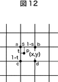
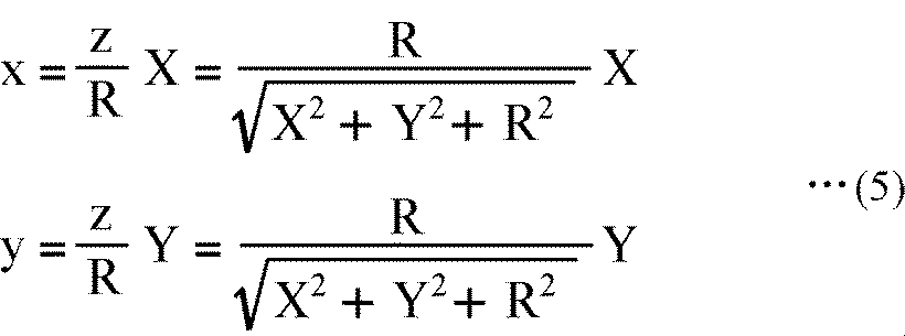
- FIG. 11 shows the pixel position (X, Y) of a pixel in a corrected image of a predetermined size obtained by distortion correction and the pixel position (x) of a pixel in a subimage (circumferential fisheye image) before distortion correction.
- y) is a diagram for explaining the correspondence.
- the upper hemisphere of the radius R is considered, with the center of the circumferential fisheye image as the origin of the xyz coordinates and the circumferential fisheye image as the cut surface at the diameter.
- the corrected image is in contact with the upper hemisphere at point (0, 0, R).
- the distortion correction unit 52 sets the pixel value of point (X, Y) in the corrected image after correction as the pixel value of point (x, y) in the corresponding circumferential fisheye image before correction. Generate a corrected image.
- the point (x, y) in the circumferential fisheye image before correction corresponding to the point (X, Y) in the corrected image after correction is located at the grid point in the arrangement of the pixels. If not, surrounding pixels (pixel values) a to d may be interpolated to obtain pixel values of point (x, y).
- a method of interpolation bilinear interpolation, bicubic interpolation or the like is used.
- the optical axis correction unit 53 aligns the optical axis of the sub lens 32 with the optical axis of the main lens 31, and is synthesized with the sub image in the sub image from the distortion correction unit 52. Determine the location of the main image.
- the optical axis correction unit 53 supplies the image processing unit 54 with position information indicating the position and the sub image.
- FIG. 13 is a view for explaining the relationship between the coordinate system of the optical axis of the main lens 31 (main lens coordinate system) and the coordinate system of the optical axis of the sub lens 32 (sub lens coordinate system).
- the optical axis correction unit 53 can align the optical axis (coordinates) of the sub lens 32 with the optical axis (coordinates) of the main lens 31 using this relationship.
- the optical axis correction unit 53 matches the image in the area near the center of the sub image from the distortion correction unit 52 with the main image from the imaging unit 55 corresponding to the area, thereby the sub image Determine the position of the main image to be synthesized.
- the image processing unit 54 performs predetermined image processing on the sub image from the optical axis correction unit 53 so as to lower the image quality than the main image. More specifically, the image processing unit 54 reduces the luminance, saturation, or lightness of the sub-image.
- the image processing unit 54 supplies the sub image with the lowered image quality to the combining unit 57 together with the position information from the optical axis correction unit 53.
- the image processing unit 54 may extract only the luminance signal of the sub image and supply the black and white image to the combining unit 57.
- step S14 the image processing unit 56 performs predetermined image processing on the main image from the imaging unit 55 so as to improve the image quality more than the sub image. More specifically, the image processing unit 56 raises the luminance, saturation, or lightness of the main image. The image processing unit 56 supplies the main image with the improved image quality to the combining unit 57.
- the image processing unit 56 may add a frame of a predetermined color or line type around the main image and supply the frame to the combining unit 57.
- step S15 the combining unit 57 combines the main image from the image processing unit 56 with the sub image from the image processing unit 54 based on the position information from the image processing unit 54, and displays the combined image as a display unit. Supply to 58.
- the size of the main image needs to be smaller than that of the sub-image, which depends on the size of the imaging element provided in each of the imaging unit 51 and the imaging unit 55.
- the size of the imaging device provided in each of the imaging unit 51 and the imaging unit 55 is the same, images in different ranges are generated as images of the same size. Therefore, in order to combine the main image and the sub image, it is necessary to adjust the size of one of the images.
- the distance between the origin and the imaging element of the imaging unit 51 for capturing the sub image I s is defined as f s.
- the captured area on the imaging element of the imaging unit 55 of the main image I m and l m, caught on the imaging unit 51 of the sub-image I s Let the range be l s . Also, let l be the size of the imaging device of each of the imaging unit 51 and the imaging unit 55.
- Equation (6) the ratio l m / l s of the magnitude of the size and the sub-image I s of the main image I m is determined by the following equation (7).
- the combining unit 57 generates the main image I ′ m by multiplying the size of the main image I m by f s / f m and combines it with the sub image I s .
- the size of the imaging device of the imaging unit 51 and the imaging unit 55 is not limited to the case were identical, the relationship of the size of the main image I m and the sub-image I s is not like the D in FIG. 14 in this case, by predetermined multiple of the size of the main image I m, it is possible to adjust the size of the main image.
- step S16 the display unit 58 displays the composite image from the composition unit 57.
- the composite image in which the standard image of the angle of view to be captured is composited is displayed at the center of the wide-angle image with reduced image quality as shown in FIG. At the same time, you can easily check the image of.
- the user can confirm the composition other than the angle of view desired to be photographed in the wide-angle image, the user can also search for a better composition.
- the image quality is lowered for images other than the angle of view desired to be photographed, and only the composition is confirmed.
- an object included in the image other than the angle of view desired to be photographed is emphasized and displayed. It is also good.
- FIG. 15 shows a configuration example of a digital camera that displays an object in an image other than the angle of view desired to be captured.
- components having the same functions as those provided for the digital camera 11 of FIG. 3 are given the same names and reference numerals, and the description thereof will be omitted as appropriate. I assume.
- the digital camera 121 of FIG. 15 differs from the digital camera 11 of FIG. 3 in that an object detection unit 151 and an image processing unit 152 are newly provided, and a synthesis unit 153 is provided instead of the synthesis unit 57. is there.
- the optical axis correction unit 53 of FIG. 15 supplies the image processing unit 54 with the sub image subjected to the optical axis correction and the position information indicating the position at which the main image in the sub image is to be synthesized. Are supplied to the object detection unit 151.
- the object detection unit 151 detects an object in the sub image from the optical axis correction unit 53, and detects an image of a region including the detected object (detected object image) along with position information indicating a position in the sub image. Supply to 152.
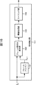
- FIG. 16 shows a first configuration example of the object detection unit 151.
- the object detection unit 151 in FIG. 16 includes a frame buffer 161, an inter-frame difference calculation unit 162, a threshold processing unit 163, and a labeling unit 164.
- the frame buffer 161 stores the sub-image from the optical axis correction unit 53 for each frame.
- the inter-frame difference calculation unit 162 reads the sub-image I t-1 of the previous frame stored in the frame buffer 161, and the sub-image I t-1 and the sub-image of the current frame from the optical axis correction unit 53. and a I t, for each pixel, and calculates an inter-frame difference value is a difference between the pixel values.
- the inter-frame difference calculation unit 162 supplies the calculation result to the threshold processing unit 163.
- the threshold processing unit 163 Based on the inter-frame difference value from the inter-frame difference calculation unit 162, the threshold processing unit 163 sets 1 as a pixel having a difference value equal to or more than a predetermined threshold and 2 as a pixel having a difference value smaller than the predetermined threshold. Make it valuable.
- the threshold processing unit 163 divides the binarized image into predetermined blocks, counts pixels having a pixel value of 1 in each block, and counts the predetermined threshold or more based on the count number. A block with a number is detected as a motion block. Then, the threshold processing unit 163 supplies the detection result (motion block) to the labeling unit 164.
- the labeling unit 164 performs labeling processing based on the motion block supplied from the threshold processing unit 163. Furthermore, the labeling unit 164 detects a rectangle (a circumscribed frame) surrounding each labeled block from the outside, and supplies the detection result to the image processing unit 152 as a detected object image.
- the object detection unit 151 can detect an object with motion in the sub image.
- FIG. 17 shows a second configuration example of the object detection unit 151.
- the object detection unit 151 in FIG. 17 is configured of a face detection unit 171.
- the face detection unit 171 detects a face from the sub-image I t from the optical axis correcting unit 53 extracts a face image based on the position and size of the face detection area is an area to detect the face, detected object
- the image is supplied to the image processing unit 152 as an image.
- the face detection unit 171 learns a face image of a face are oriented in various directions, the sub-image I t, an image of a region of the same size as the face detection area, the learning face image A face is detected by comparing and evaluating whether it is a face or not.
- the object detection unit 151 can detect a human face in the sub image.
- the object detection unit 151 detects a moving object or a person (face).
- the present invention is not limited to this, and a predetermined object (car, building, etc.) is detected. You may do it.
- the image processing unit 152 performs predetermined image processing (picture, brightness, color saturation, and color tone) on the detected object image from the object detection unit 151 so as to improve the image quality compared to the sub image. , Adjustment of sharpness, etc., and is supplied to the combining unit 153 together with the position information.
- predetermined image processing picture, brightness, color saturation, and color tone
- FIG. 18 shows an example of the configuration of the image processing unit 152 that performs enhancement processing on a detected object image.
- the image processing unit 152 in FIG. 18 includes an RGB / YUV conversion unit 181, an HPF 182, an amplifier 183, an adder 184, and a YUV / RGB conversion unit 185.
- the RGB / YUV conversion unit 181, the HPF 182, the amplifier 183, the adder 184, and the YUV / RGB conversion unit 185 are the RGB / YUV conversion unit 91, the HPF 92, the amplifier 93, provided in the image processing unit 56 of FIG. Since the function similar to that of the adder 94 and the YUV / RGB converter 95 is provided, the description thereof is omitted.
- the image processing unit 152 can perform an enhancement process on the detected object image.
- the combining unit 153 combines the main image from the image processing unit 56 and the sub image from the image processing unit 54 based on the position information from the image processing unit 54. Furthermore, based on the position information from the image processing unit 152, the combining unit 153 combines the detected object image from the object detection unit 151 with the area corresponding to the sub image of the combined image, and displays the combined image. It supplies to the part 58.
- step S34 the object detection unit 151 performs an object detection process of detecting an object in the sub image from the optical axis correction unit 53.
- the object detection unit 151 supplies an image of an area including the detected object (detected object image) to the image processing unit 152 together with position information indicating a position in the sub image.
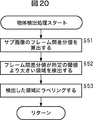
- step S51 the inter-frame difference calculation unit 162 reads the sub-image It -1 of the previous frame stored in the frame buffer 161, and the sub-image It -1 and the current from the optical axis correction unit 53. and a sub-image I t of the frame, for each pixel, and calculates a difference value between frames.
- the inter-frame difference calculation unit 162 supplies the calculation result to the threshold processing unit 163.
- step S52 based on the inter-frame difference value from the inter-frame difference calculation unit 162, the threshold processing unit 163 sets a pixel having a difference value greater than or equal to a predetermined threshold as 1 and a pixel of a difference value less than the predetermined threshold. Is binarized as 0.
- the threshold processing unit 163 divides the binarized image into predetermined blocks, counts pixels having a pixel value of 1 in each block, and counts the predetermined threshold or more based on the count number. A block with a number is detected as a motion block. Then, the threshold processing unit 163 supplies the detection result (motion block) to the labeling unit 164.
- step S53 the labeling unit 164 performs labeling processing based on the motion block supplied from the threshold processing unit 163. Furthermore, the labeling unit 164 detects a rectangle (a circumscribed frame) surrounding each labeled block from the outside, and supplies the detection result to the image processing unit 152 as a detected object image.
- a human face may be detected.
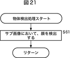
- step S61 the face detection unit 171 detects a face from the sub-image I t from the optical axis correcting unit 53, extracts a face image based on the position and size of the face detection area is an area for detecting a face Then, it is supplied to the image processing unit 152 as a detected object image.
- the object detection processing described with reference to the flowcharts of FIGS. 20 and 21 can be performed in parallel by causing the object detection unit 151 of the digital camera 121 to have the configuration described with reference to FIGS. You can
- the image processing unit 152 subjects the detected object image from the object detection unit 151 to predetermined image processing so as to improve the image quality compared to the sub image, and combines with the position information. It supplies to the part 153. More specifically, the image processing unit 152 increases the luminance, saturation, or lightness of the detected object image. The image processing unit 152 supplies the detected object image with improved image quality to the combining unit 153.
- the image processing unit 152 may add a frame of a predetermined color around the detected object image, and supply the frame to the combining unit 153.
- step S37 the combining unit 153 combines the main image from the image processing unit 56 with the sub image from the image processing unit 54 based on the position information from the image processing unit 54. Furthermore, the combining unit 153 displays the detected object image from the object detection unit 151 in, for example, an area corresponding to the sub image of the combined image synthesized based on the position information from the image processing unit 152, for example, in FIG. And the synthesized image is supplied to the display unit 58.
- FIG. 22 shows an example of a composite image in which a detected object image is highlighted.
- a detected object image 201 and a detected object image 202 are displayed in the area corresponding to the sub image of the composite image.
- a detected object image 201 is an image of a dog as a moving object
- the object detection unit 151 in FIG. 16 detects an object (dog)
- the image processing unit 152 detects the detected object image 201. By enhancing the image quality, it is highlighted in the composite image.
- the detected object image 202 is an image of a person, and the object detection unit 151 in FIG. 17 detects a human face, and the image processing unit 152 improves the image quality of the detected object image 202 to obtain a composite image. It is highlighted.
- the standard image of the angle of view to be shot is synthesized at the center of the wide-angle image with lowered image quality, and the image in which the object included in the image other than the angle of view to be photographed is enhanced is synthesized.
- the composite image is displayed. Therefore, the user can easily check the images of the two compositions simultaneously, and can check the objects included in the images other than the angle of view desired to be captured.
- the object is detected only in the sub-image.
- the object may be detected in the main image.
- the object is emphasized in the sub image, and the image quality in the main image It is possible to lower the
- the display of the object can be made inconspicuous.
- the angle of view to be captured with a more appropriate composition may be displayed on the composite image.
- FIG. 23 shows an example of the configuration of a digital camera in which the user is made to display the angle of view to be taken with a more appropriate composition on the composite image.
- the digital camera 221 of FIG. 23 the same name and the same reference numeral are given to the configuration having the same function as that provided to the digital camera 121 of FIG. 15, and the description thereof is appropriately omitted. I assume.
- the digital camera 221 of FIG. 23 differs from the digital camera 121 of FIG. 15 in that the composition analysis unit 251 and the recommended composition extraction unit 252 are newly provided, and the image processing unit 152 and the combining unit 153 are replaced by image processing. The point is that the unit 253 and the combining unit 254 are provided.
- the object detection unit 151 shown in FIG. 23 detects an object in the sub-image from the optical axis correction unit 53, and detects position information representing the position of the detected object in the sub-image and the sub-image to the composition analysis unit 251. Supply.
- the composition analysis unit 251 analyzes and determines the composition corresponding to the arrangement of the object in the sub image based on the sub image from the object detection unit 151 and the position information of the object in the sub image. For example, the composition analysis unit 251 stores a plurality of composition patterns in advance, selects a composition pattern closest to the arrangement of objects in the sub image from the composition patterns by pattern matching, and corresponds to the sub image It is considered as a composition (recommended composition). The composition analysis unit 251 supplies composition information (for example, the upper left position and the lower right position of the rectangle that is the outline of the composition) indicating the determined composition to the recommended composition extraction unit 252 together with the sub image.
- composition information for example, the upper left position and the lower right position of the rectangle that is the outline of the composition
- the recommended composition extraction unit 252 extracts a recommended composition image (recommended composition image) from the sub image based on the composition information and the sub image from the composition analysis unit 251, and supplies the image with the composition information to the image processing unit 253. .
- the image processing unit 253 has the same function as the image processing unit 56, and performs predetermined image processing (picture, brightness, etc.) on the recommended composition image from the recommended composition extraction unit 252 so as to improve the image quality compared to the sub image. , Adjustment of color density, color tone, sharpness and the like), and is supplied to the composition unit 254 together with composition information.
- predetermined image processing picture, brightness, etc.
- the combining unit 254 combines the main image from the image processing unit 56 and the sub image from the image processing unit 54 based on the position information from the image processing unit 54. Furthermore, the combining unit 254 combines the recommended composition image from the image processing unit 253 in the area corresponding to the sub image of the combined image based on the composition information from the image processing unit 253, and displays the combined image. It supplies to the part 58.
- step S75 the composition analysis unit 251 analyzes the composition corresponding to the arrangement of the object in the sub-image based on the sub-image from the object detection unit 151 and the position information of the object in the sub-image, and recommends composition Decide.
- the composition analysis unit 251 stores a plurality of composition patterns in advance, selects a composition pattern closest to the arrangement of objects in the sub image from the composition patterns by pattern matching, and corresponds to the sub image
- the recommended composition is The composition analysis unit 251 supplies composition information indicating the determined composition to the recommended composition extraction unit 252 together with the sub image.
- FIG. 25 shows an example of the recommended composition determined by the composition analysis unit 251.
- the composition shown in FIG. 25 is a composition called a three-part composition, in which the object (subject) is placed at any position of the intersections of vertical lines and horizontal lines (in the figure, filled circles) to achieve balance. It is known that it will be an image (photograph).
- the composition (composition pattern) determined by the composition analysis unit 251 is not limited to a three-divided composition, but is a horizontal line composition used when it is desired to have left and right spread, and a vertical line composition used when emphasizing the vertical direction. It is assumed that there are a plurality of comparison compositions, etc., which are used when two identical or similar ones are lined up.
- the recommended composition extraction unit 252 extracts a recommended composition image from the sub image based on the composition information and the sub image from the composition analysis unit 251, and performs image processing with the composition information. It supplies to the part 253.
- step S77 the image processing unit 253 performs predetermined image processing on the recommended composition image from the recommended composition extraction unit 252 so as to improve the image quality of the sub image, and supplies the composition information with the composition information.
- the image processing unit 253 may add a frame of a predetermined color or line type around the recommended composition image and supply the frame to the combining unit 254.
- the combining unit 254 combines the main image from the image processing unit 56 with the sub image from the image processing unit 54 based on the position information from the image processing unit 54. Furthermore, the combining unit 254 displays a recommended composition image from the image processing unit 253, for example, in FIG. 26, in an area corresponding to the sub image of the combined image synthesized based on the composition information from the image processing unit 253. And the synthesized image is supplied to the display unit 58.
- FIG. 26 shows an example of a composite image on which a recommended composition is displayed.
- FIG. 26 in addition to the composite image shown in FIG. 2, a recommended composition is shown on the composite image by a broken line representing its outline.
- the image quality of the image in the recommended composition is higher than the image quality of the sub-image, but when part of the main image (current angle of view) and part of the recommended composition overlap, There is a fear that they can not be distinguished. Therefore, as shown in FIG. 26, the outline (field angle) may be simply displayed as a recommended composition.
- the recommended composition can be displayed on the composite image.
- the recommended composition is displayed on the composite image, so that the user can confirm a more appropriate composition than the composition to be photographed (recorded).
- an imaging device 301 having an aspect ratio of 4: 3 (or 3: 2) as shown in FIG.
- an imaging device 301 having an aspect ratio of 4: 3 (or 3: 2) as shown in FIG.
- an imaging device 301 having an aspect ratio of 4: 3 (or 3: 2) as shown in FIG.
- an imaging device 301 having an aspect ratio of 4: 3 (or 3: 2) as shown in FIG.
- an imaging device 301 having an aspect ratio of 4: 3 (or 3: 2) as shown in FIG.
- an imaging device 301 having an aspect ratio of 4: 3 (or 3: 2) as shown in FIG.
- the standard mode an image having an aspect ratio of 4: 3 (or 3: 2) is captured, displayed, and recorded using the entire imaging device 301.
- the panoramic mode the imaging element of the rectangular area 313 having an aspect ratio of 16: 9 is used without using the imaging elements of the upper area 311 and the lower area 312 in the imaging element 301 of FIG.
- An image having an aspect ratio of 16: 9 is captured, displayed, and recorded.
- the display area of the display unit for displaying a so-called live view is configured to display an image corresponding to the entire imaging element 301 of FIG. Therefore, when the user shoots an object in the panoramic mode, the display area in which the through image is displayed on the display unit is an area corresponding to the rectangular area 313 in the entire imaging device 301 in FIG.
- FIG. 28 shows a configuration example of a digital camera provided with only one imaging system.
- the digital camera 411 in FIG. 28 includes a lens 431, an imaging unit 432, an image processing unit 433, a cutout unit 434, an extraction unit 435, a combining unit 436, a display control unit 437, a display unit 438, an operation input unit 439, and a recording control unit 440. , And a recording unit 441.
- the lens 431 is a so-called standard lens similar to the main lens 31 of the digital camera in FIG.
- the imaging unit 432 is configured to include an imaging device such as a CCD (Charge Coupled Device) having an aspect ratio of 4: 3, and an A / D conversion unit.
- the imaging unit 432 receives light from the lens 431 and performs photoelectric conversion to image a subject, and A / D converts the obtained analog image signal.
- the imaging unit 432 supplies digital image data (hereinafter, referred to as a captured image) obtained as a result of A / D conversion to the image processing unit 433.
- the image processing unit 433 performs predetermined image processing on the captured image from the imaging unit 432.
- the image processing unit 433 supplies the captured image subjected to the image processing to the display control unit 437 and the recording control unit 440 when the imaging mode is a standard mode for capturing an image with an aspect ratio of 4: 3. Further, when the imaging mode is a panoramic mode for capturing an image with an aspect ratio of 16: 9, the image processing unit 433 supplies the captured image subjected to the image processing to the cutting out unit 434 and the extracting unit 435.
- the cutting out unit 434 cuts out an image with an aspect ratio of 16: 9, which is different in size from the captured image, from the captured image.
- the cutting out unit 434 supplies the cut out image (cut out image) to the combining unit 436, the display control unit 437, or the recording control unit 440 as necessary.
- the extraction unit 435 detects a subject with high degree of attention in the captured image, includes the subject, and has a size different from that of the captured image, with an aspect ratio of 16: 9. Extract the image of the area to be The extracting unit 435 supplies the extracted image (extracted image) to the combining unit 436 or the recording control unit 440 as necessary.
- the synthesizing unit 436 synthesizes the cutout image from the cutout unit 434 and the extraction image from the extracting unit 435, and supplies the synthesized image to the display control unit 437.
- the display control unit 437 controls the display unit 438 to display various images on the display unit 438.
- the display control unit 437 causes the display unit 438 to display the captured image supplied from the image processing unit 433.
- the display control unit 437 causes the display unit 438 to display the cutout image supplied from the cutout unit 434 or the composite image supplied from the synthesis unit 436.
- the display unit 438 properly displays various images under the control of the display control unit 437.
- the operation input unit 439 is operated by the user to input an instruction to the digital camera 411.
- the operation input unit 439 includes, for example, various operation buttons, a remote control, a touch panel, and a microphone, receives an operation from the user, and supplies a signal (information) indicating the operation content to each block of the digital camera 411 .
- the recording control unit 440 controls the recording unit 441.
- the recording control unit 440 causes the recording unit 441 to record the captured image from the image processing unit 433 based on the signal from the operation input unit 439.
- the recording control unit 440 records the cutout image from the cutout unit 434 and the extraction image from the extraction unit 435 in the recording unit 441 based on the signal from the operation input unit 439.
- the recording control unit 440 reads an image from the recording unit 441 based on the signal from the operation input unit 439, and supplies the image to the display control unit 437.
- the recording unit 441 appropriately records various images under the control of the recording control unit 440.
- step S111 the imaging unit 432 captures an image of a subject. More specifically, the imaging unit 432 images a subject by receiving light from the lens 431 and performing photoelectric conversion, A / D converts the obtained analog image signal, and obtains the acquired image.
- the image processing unit 433 is supplied.
- step S112 the image processing unit 433 performs image processing such as demosaicing processing, white balance adjustment processing, and gamma correction processing on the captured image from the imaging unit 432, and supplies the image processing to the cutout unit 434 and the extraction unit 435.
- image processing such as demosaicing processing, white balance adjustment processing, and gamma correction processing
- the cutout unit 434 cuts out an image with an aspect ratio of 16: 9 from the captured image supplied from the image processing unit 433 and supplies the cutout image obtained as a result to the combining unit 436. More specifically, the cutout unit 434 cuts an image of a portion corresponding to the rectangular area 313 in the imaging element 301 described in FIG. 27 in the captured image having an aspect ratio of 4: 3 from the image processing unit 433. put out.
- the cutout unit 434 corresponds to the area of the captured image 511 indicated by the dashed dotted line.
- the image is clipped to obtain a clipped image 512 shown on the right side of FIG.
- the cut-out image 512 having an aspect ratio of 16: 9 the cat as the subject is generally located upward, and the top of the head including the ear is missing. There is.
- the clipped image 512 can not be said to be an image of a good composition as an image captured and displayed in the panoramic mode.
- a conventional digital camera including an image sensor having an aspect ratio of 4: 3
- the image displayed on the display unit is captured by the entire image sensor
- the captured image 511 is an image of a region indicated by an alternate long and short dash line in FIG.
- an image such as the cutout image 512 in FIG. 30 may be displayed on the display unit and recorded.
- the extraction unit 435 detects a subject with a high degree of interest in the captured image supplied from the image processing unit 433.
- the extracting unit 435 extracts an image of a region having an aspect ratio of 16: 9 including the subject, and supplies the extracted image obtained as a result to the synthesizing unit 436.
- the extraction unit 435 indicates a luminance information map indicating information on luminance, a color information map indicating information on color, an edge information map indicating information on edges, and information on motion in each region of the captured image. Generate a motion information map.
- the information map is simply referred to as an information map
- the information included in the information map is more included in the area including the subject. It is considered as information indicating the feature amount of the feature.
- information in which the information is arranged corresponding to each area of the captured image is used as an information map. That is, it can be said that the information map is information indicating the feature amount in each area of the captured image.
- an area on the captured image corresponding to an area having a larger amount of information in each information map, that is, an area having a large amount of feature amounts is an area having a higher possibility of including the subject. It is possible to identify the included area of
- the extraction unit 435 specifies an area having an aspect ratio of 16: 9, which includes the subject in the captured image, based on the luminance information map, the color information map, the edge information map, and the motion information map.
- the image of is extracted as an extracted image.
- the extraction unit 435 detects a cat as a subject in the captured image 511 as an object with a high degree of attention
- the image of the area (aspect ratio 16: 9) indicated by the broken line is extracted so as to include the subject, and the extracted image 513 shown on the right side of FIG. 31 is obtained.
- the cat which is the subject, is located approximately at the center of the extracted image 513 having an aspect ratio of 16: 9.
- the extracted image 513 can be said to be an image of a good composition as an image captured and displayed in the panoramic mode.
- a method of extracting information such as luminance, color, and edge from a captured image is described in detail in, for example, “Laurent Itti, Christof Koch, and Ernst Niebur,“ A Model of Saliency-Based Visual Attention for Rapid Scene Analysis ”. It is done.
- the combining unit 436 combines the cutout image from the cutout unit 434 and the extraction image from the extraction unit 435 so that the positions of the subject coincide with each other. Are supplied to the display control unit 437.
- step S116 the display control unit 437 causes the display unit 438 to display the composite image supplied from the combining unit 436.
- FIG. 32 illustrates an example of a composite image displayed on the display unit 438.
- the display area of the display unit 438 of the digital camera 411 has an aspect ratio of 4: 3.
- the display control unit 437 displays a black image (a so-called black band) in the upper and lower areas of the display area of the display unit 438 to display a display area with an aspect ratio of 16: 9. Form.
- the display control unit 437 causes the display area of the display unit 438 to display a portion corresponding to the cutout image in the composite image in the display area with an aspect ratio of 16: 9. Further, the display control unit 437 causes the display unit 438 to display a frame indicated by a broken line in the drawing so as to emphasize a portion corresponding to the extracted image in the composite image. At this time, of the portion corresponding to the extracted image in the composite image, the portion covering the black band (upper side) of the display area of the display unit 438 is displayed as a composite image with low luminance. Note that the extracted image displayed on the display unit 438 may be highlighted so that the user can confirm the display range of the extracted image, in addition to being emphasized by a frame as shown in FIG.
- the image of the composition that the user is going to shoot and the image of the composition in which the subject with high degree of attention is located at the center are combined. Since it can be displayed, the user can confirm a more appropriate composition than the composition to be photographed (recorded).
- the display area of the display unit 438 is configured to display the pickup image and the extraction image together.
- the brightness of the portion applied to the black band may be lowered.
- the extracted image is supplied to the display control unit 437 and the recording control unit 440 in step S213, and the extracted image is transmitted to the recording control unit 440 in step S214.
- the process is basically the same as the process of steps S111 to S114 in the flowchart of FIG. 29 except for the point of supply, and therefore the description thereof is omitted.
- step S215 the display control unit 437 causes the display unit 438 to display the cutout image supplied from the cutout unit 434. More specifically, the display control unit 437 displays the cutout image in the display area with an aspect ratio of 16: 9 in the display unit 438 as described with reference to FIG. At this time, black bands are displayed in the upper area and the lower area in the display area of the display unit 438.
- step S216 the recording control unit 440 determines whether the shutter button as the operation input unit 439 has been pressed.
- step S216 If it is determined in step S216 that the shutter button has not been pressed, the process returns to step S211, and the subsequent processes are repeated.
- step S216 if it is determined in step S216 that the shutter button has been pressed, that is, if a signal indicating that the shutter button has been pressed is supplied from the operation input unit 440 to the recording control unit 440, the process proceeds to step S217. move on.
- step S 217 the recording control unit 440 causes the recording unit 441 to record the cutout image from the cutout unit 434 and the extraction image from the extraction unit 435 based on the signal from the operation input unit 440.
- the recording unit 441 the cutout image 512 described in FIG. 30 and the extracted image 513 described in FIG. 31 are recorded.
- the cutout image and the extraction image can be recorded in the panoramic mode, an image of a composition photographed by a user who is not accustomed to photographing and an image of a composition more appropriate for the user than the composition photographed It is possible to record
- the user can compare the two images, which helps the user to improve the photographing technology. It becomes.
- the cut out image and the extracted image are recorded in the recording unit 441, but the composite image obtained by combining the cut out image and the extracted image described in the flowchart of FIG. You may make it
- FIG. 34 shows an example of a composite image recorded in the recording unit 441.
- a portion indicated by an alternate long and short dash line corresponds to a cutout image
- a portion indicated by a broken line corresponds to an extraction image.
- the composite image 601 is considered divided into three regions 611 to 613.
- the region 611 is a portion which does not exist in the cutout image but exists in the extraction image
- the region 612 is a portion which exists in both the cutout image and the extraction image
- the region 613 exists in the cutout image
- the recording control unit 440 reads out the area 612 and the area 613 in the composite image 601. It may be supplied to the display control unit 437.
- the recording control unit 440 reads the area 611 and the area 612 in the composite image 601, and the display control unit It may be supplied to 437.
- the image corresponding to the area 611 and the cutout image may be recorded together, or the extracted image and the image corresponding to the area 613 may be recorded together. You may
- the extracted image is recorded when the shutter button as the operation input unit 439 is operated.
- the composition of the extracted image is prepared in advance by using three divided compositions or horizontal lines.
- the extracted image may be recorded when it matches with a composition pattern such as a composition or a radiation composition.
- the image processing unit 433 performs predetermined image processing on image data obtained from the entire imaging element of the imaging unit 432.
- the shutter button as the operation input unit 439
- the image processing is performed on the image data obtained from the imaging device corresponding to the area 313 of the imaging device 301 in FIG. 27 until the user operates the camera, and the entire imaging device is operated when the shutter button is operated.
- Image processing may be performed on the image data obtained from the above.
- the series of processes described above can be performed by hardware or software.
- various functions may be executed by installing a computer in which programs constituting the software are incorporated in dedicated hardware or various programs.
- the program can be installed from a program storage medium, for example, on a general-purpose personal computer.
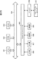
- FIG. Xx is a block diagram showing a configuration example of hardware of a computer that executes the series of processes described above according to a program.
- a central processing unit (CPU) 901, a read only memory (ROM) 902, and a random access memory (RAM) 903 are mutually connected by a bus 904.
- the input / output interface 905 is connected to the bus 904.
- the input / output interface 905 includes an input unit 906 including a keyboard, a mouse and a microphone, an output unit 907 including a display and a speaker, a storage unit 908 including a hard disk and a non-volatile memory, and a communication unit 909 including a network interface.
- a drive 910 for driving a removable medium 911 such as a magnetic disk, an optical disk, a magneto-optical disk, or a semiconductor memory is connected.
- the CPU 901 loads the program stored in the storage unit 908 into the RAM 903 via the input / output interface 905 and the bus 904 and executes the program. Processing is performed.
- the program executed by the computer (CPU 901) is, for example, a magnetic disk (including a flexible disk), an optical disk (CD-ROM (Compact Disc-Read Only Memory), DVD (Digital Versatile Disc), etc.), a magneto-optical disk, or a semiconductor It is recorded on a removable medium 911 which is a package medium including a memory or the like, or provided via a wired or wireless transmission medium such as a local area network, the Internet, or digital satellite broadcasting.
- the program can be installed in the storage unit 908 via the input / output interface 905 by attaching the removable media 911 to the drive 910.
- the program can be received by the communication unit 909 via a wired or wireless transmission medium and installed in the storage unit 908.
- the program can be installed in advance in the ROM 902 or the storage unit 908.
- the program executed by the computer may be a program that performs processing in chronological order according to the order described in this specification, in parallel, or when necessary, such as when a call is made. It may be a program to be processed.
Landscapes
- Engineering & Computer Science (AREA)
- Multimedia (AREA)
- Signal Processing (AREA)
- Theoretical Computer Science (AREA)
- Physics & Mathematics (AREA)
- General Physics & Mathematics (AREA)
- Human Computer Interaction (AREA)
- Computing Systems (AREA)
- Image Processing (AREA)
- Studio Devices (AREA)
- Indication In Cameras, And Counting Of Exposures (AREA)
- Editing Of Facsimile Originals (AREA)
Abstract
Description
1.第1の実施の形態
2.第2の実施の形態
3.第3の実施の形態
4.第4の実施の形態
[撮像装置の外観と撮像画像]
図1は、本発明を適用した撮像装置の一実施の形態としてのデジタルカメラの外観の例を示している。
次に、図3のブロック図を参照して、デジタルカメラ11の機能構成例について説明する。


次に、図10のフローチャートを参照して、図3のデジタルカメラ11の画像表示処理について説明する。


[デジタルカメラの構成例]
図15は、撮影したい画角以外の画像における物体を表示させるようにしたデジタルカメラの構成例を示している。なお、図15のデジタルカメラ121において、図3のデジタルカメラ11に設けられたものと同様の機能を備える構成については、同一名称および同一符号を付するものとし、その説明は、適宜省略するものとする。
次に、図19のフローチャートを参照して、図15のデジタルカメラ121の画像表示処理について説明する。なお、図19のフローチャートにおけるステップS31乃至S33,S36の処理は、図10のフローチャートを参照して説明したステップS11乃至S14の処理と同様であるので、その説明は省略するものとする。
フレーム間差分算出部162は、算出結果を閾値処理部163に供給する。
[デジタルカメラの構成例]
図23は、ユーザに、より適切な構図で撮影させる画角を合成画像に表示させるようにしたデジタルカメラの構成例を示している。なお、図23のデジタルカメラ221において、図15のデジタルカメラ121に設けられたものと同様の機能を備える構成については、同一名称および同一符号を付するものとし、その説明は、適宜省略するものとする。
次に、図24のフローチャートを参照して、図23のデジタルカメラ221の画像表示処理について説明する。なお、図24のフローチャートにおけるステップS71乃至S74,S78の処理は、図10のフローチャートを参照して説明したステップS31乃至S34,S36の処理と同様であるので、その説明は省略するものとする。
[デジタルカメラの機能構成例]
図28は、1つのみの撮像系を備えるデジタルカメラの構成例を示している。
画像処理部433は、撮像モードが、アスペクト比が4:3である画像を撮像する標準モードである場合、画像処理を施した撮像画像を、表示制御部437および記録制御部440に供給する。また、画像処理部433は、撮像モードが、アスペクト比が16:9である画像を撮像するパノラマモードである場合、画像処理を施した撮像画像を、切出し部434および抽出部435に供給する。
さらに、記録制御部440は、操作入力部439からの信号に基づいて、記録部441から画像を読み出して、表示制御部437に供給する。
次に、図29のフローチャートを参照して、図28のデジタルカメラ411の画像表示処理について説明する。なお、図29の画像表示処理は、ユーザによって、操作入力部439が、撮像モードとしてパノラマモードを選択する旨の操作を受け付けた場合に開始される。
ここで、図33のフローチャートを参照して、図28のデジタルカメラ411の画像記録処理について説明する。なお、図33の画像記録処理は、ユーザによって、操作入力部439が、撮像モードとしてパノラマモードを選択する旨の操作を受け付けた場合に開始される。
Claims (18)
- 被写体を撮像した第1の画像と、前記第1の画像と撮像の範囲の異なる第2の画像とを、前記被写体の位置が一致するように合成する合成手段と、
前記合成手段によって合成された前記第1の画像および前記第2の画像を表示する表示手段と
を備える撮像装置。 - 光学系からの光を受光して、前記被写体の前記第1の画像を撮像する撮像手段と、
前記第1の画像から、前記第1の画像とサイズの異なる画像であって、注目度の高い前記被写体を含む第2の画像を抽出する抽出手段をさらに備え、
前記合成手段は、前記第1の画像に、前記被写体の位置が一致するように、前記抽出手段によって抽出された前記第2の画像を合成し、
前記表示手段は、前記第1の画像全体を表示可能な表示領域における前記第2の画像と同一サイズの所定領域に、対応する部分の前記第1の画像を表示するとともに、前記第1の画像と合成された前記第2の画像を表示する
請求項1に記載の撮像装置。 - 前記表示手段は、前記表示領域において、前記第2の画像を強調して表示する
請求項2に記載の撮像装置。 - 前記表示領域は、撮像モードが、アスペクト比が4:3である画像を撮像する標準モードであるときに、前記第1の画像全体が表示される領域であり、
前記表示領域における前記所定領域は、撮像モードが、アスペクト比が16:9である画像を撮像するパノラマモードであるときに、前記第1の画像の一部が表示される領域である
請求項2に記載の撮像装置。 - 前記所定領域の前記第1の画像を切出す切出し手段と、
前記切出し手段によって切出された前記第1の画像、および、前記抽出手段によって抽出された前記第2の画像を記録する記録手段とをさらに備える
請求項2に記載の撮像装置。 - 前記合成手段は、前記切出し手段によって切出された前記第1の画像と、前記抽出手段によって抽出された前記第2の画像とを合成し、
前記記録手段は、前記合成手段によって合成された前記第1の画像および前記第2の画像を記録する
請求項5に記載の撮像装置。 - 第1の光学系からの光を受光して、前記被写体の前記第1の画像を撮像する第1の撮像手段と、
第2の光学系からの光を受光して、前記被写体の、前記第1の画像と画角の異なる第2の画像を撮像する第2の撮像手段と、
前記第2の画像の画質を、前記第1の画像の画質と異なるように調整する第1の画質調整手段とをさらに備え、
前記合成手段は、前記第1の画質調整手段によって画質が調整された前記第2の画像に、前記被写体の位置が一致するように、前記第1の画像を合成する
請求項1に記載の撮像装置。 - 前記第2の画像中の物体を検出する物体検出手段と、
前記物体検出手段によって検出された前記第2の画像中の前記物体の領域の画質を、前記第2の画像の画質と異なるように調整する第2の画質調整手段と
をさらに備え、
前記合成手段は、前記第2の画像に、前記被写体の位置が一致するように、前記第1の画像、および前記第2の画質調整手段によって画質が調整された前記第2の画像中の前記物体の領域の物体画像を合成する
請求項7に記載の撮像装置。 - 前記物体検出手段は、前記第2の画像中の動きのある前記物体を検出する
請求項8に記載の撮像装置。 - 前記物体検出手段は、前記第2の画像中の人の顔を検出する
請求項8に記載の撮像装置。 - 前記第2の画像の構図を解析する構図解析手段と、
前記構図解析手段によって解析された構図に基づいて、前記第1の画像の画角とは異なる画角の構図を前記第2の画像から抽出する構図抽出手段と
をさらに備え、
前記合成手段は、前記第2の画像に、前記被写体の位置が一致するように、前記第1の画像、および前記構図抽出手段に抽出された構図の抽出画像を合成する
請求項7に記載の撮像装置。 - 前記第2の撮像手段は、前記第2の光学系からの光を受光して、前記被写体の、前記第1の画像より画角の広い前記第2の画像を撮像する
請求項7に記載の撮像装置。 - 前記第2の画像の歪を補正する歪補正手段と、
前記第2の光学系の光軸を、前記第1の光学系の光軸に合わせて、前記第2の画像に合成される前記第1の画像の位置を決定する光軸補正手段とをさらに備える
請求項7に記載の撮像装置。 - 前記第1の画質調整手段は、前記第2の画像の色信号のレベルを、前記第1の画像の色信号のレベルより下げるように調整する
請求項7に記載の撮像装置。 - 前記第1の画像の画質を、前記第2の画像の画質と異なるように調整する第2の画質調整手段をさらに備える
請求項7に記載の撮像装置。 - 前記第2の画質調整手段は、前記第1の画像の色信号のレベルを、前記第2の画像の色信号のレベルより上げるように調整する
請求項15に記載の撮像装置。 - 被写体を撮像した第1の画像と、前記第1の画像と撮像の範囲の異なる第2の画像とを合成する合成ステップと、
前記合成ステップの処理によって合成された前記第1の画像および前記第2の画像を表示する表示ステップと
を含む撮像方法。 - 被写体を撮像した第1の画像と、前記第1の画像と撮像の範囲の異なる第2の画像とを合成する合成ステップと、
前記合成ステップの処理によって合成された前記第1の画像および前記第2の画像を表示する表示ステップと
を含む処理をコンピュータに実行させるプログラム。
Priority Applications (4)
| Application Number | Priority Date | Filing Date | Title |
|---|---|---|---|
| CN200980100878.XA CN101843092B (zh) | 2008-09-08 | 2009-09-08 | 成像设备和方法 |
| BRPI0905361-1A BRPI0905361A2 (pt) | 2008-09-08 | 2009-09-08 | Aparelho e método de formação de imagem, e, programa |
| EP09811602.3A EP2323374B1 (en) | 2008-09-08 | 2009-09-08 | Image pickup apparatus, image pickup method, and program |
| US12/740,443 US20100238313A1 (en) | 2008-09-08 | 2009-09-08 | Imaging Apparatus and Method, and Program |
Applications Claiming Priority (4)
| Application Number | Priority Date | Filing Date | Title |
|---|---|---|---|
| JP2008229308 | 2008-09-08 | ||
| JP2008-229308 | 2008-09-08 | ||
| JP2009-162415 | 2009-07-09 | ||
| JP2009162415A JP5413002B2 (ja) | 2008-09-08 | 2009-07-09 | 撮像装置および方法、並びにプログラム |
Publications (1)
| Publication Number | Publication Date |
|---|---|
| WO2010027079A1 true WO2010027079A1 (ja) | 2010-03-11 |
Family
ID=41797241
Family Applications (1)
| Application Number | Title | Priority Date | Filing Date |
|---|---|---|---|
| PCT/JP2009/065625 Ceased WO2010027079A1 (ja) | 2008-09-08 | 2009-09-08 | 撮像装置および方法、並びにプログラム |
Country Status (7)
| Country | Link |
|---|---|
| US (2) | US20100238313A1 (ja) |
| EP (1) | EP2323374B1 (ja) |
| JP (1) | JP5413002B2 (ja) |
| CN (2) | CN101843092B (ja) |
| BR (1) | BRPI0905361A2 (ja) |
| RU (1) | RU2443068C2 (ja) |
| WO (1) | WO2010027079A1 (ja) |
Cited By (3)
| Publication number | Priority date | Publication date | Assignee | Title |
|---|---|---|---|---|
| CN102196177A (zh) * | 2010-03-12 | 2011-09-21 | 索尼公司 | 图像处理设备、图像处理方法、程序以及成像设备 |
| US8472741B2 (en) | 2009-06-11 | 2013-06-25 | Sony Corporation | Image processing apparatus and image processing method |
| CN104346801A (zh) * | 2013-08-02 | 2015-02-11 | 佳能株式会社 | 图像构图评估装置、信息处理装置及其方法 |
Families Citing this family (22)
| Publication number | Priority date | Publication date | Assignee | Title |
|---|---|---|---|---|
| JP5327339B2 (ja) * | 2010-02-02 | 2013-10-30 | コニカミノルタ株式会社 | 画像処理システム、画像処理方法、およびプログラム |
| JP2011203446A (ja) * | 2010-03-25 | 2011-10-13 | Fujifilm Corp | ヘッドマウントディスプレイ装置 |
| JP5603671B2 (ja) * | 2010-06-22 | 2014-10-08 | オリンパスイメージング株式会社 | 電子機器、撮像方法、及び画像変換プログラム |
| US9538219B2 (en) * | 2011-02-04 | 2017-01-03 | Panasonic Intellectual Property Corporation Of America | Degree of interest estimating device and degree of interest estimating method |
| FR2974966A1 (fr) * | 2011-05-05 | 2012-11-09 | France Telecom | Procede de codage et de decodage d'images integrales, dispositif de codage et de decodage d'images integrales et programmes d'ordinateur correspondants |
| TWI475883B (zh) * | 2012-03-01 | 2015-03-01 | Altek Corp | 攝像裝置及其分隔式攝像方法 |
| US20130242057A1 (en) * | 2012-03-16 | 2013-09-19 | Research In Motion Limited | Methods and devices for producing an enhanced image |
| EP2640060A1 (en) * | 2012-03-16 | 2013-09-18 | BlackBerry Limited | Methods and devices for producing an enhanced image |
| EP2688060A4 (en) * | 2012-03-22 | 2015-08-05 | Sony Corp | DISPLAY DEVICE, IMAGE PROCESSING DEVICE AND IMAGE PROCESSING PROCESS AND COMPUTER PROGRAM THEREFOR |
| CN103971336B (zh) * | 2014-04-28 | 2017-02-15 | 深圳市云宙多媒体技术有限公司 | 一种图像明度的调整方法、装置和设备 |
| KR102179262B1 (ko) | 2014-06-11 | 2020-11-16 | 삼성전자주식회사 | 렌즈 왜곡 보정 장치 및 이를 포함하는 애플리케이션 프로세서 |
| KR102157675B1 (ko) * | 2014-07-25 | 2020-09-18 | 삼성전자주식회사 | 촬영 장치 및 그 촬영 방법 |
| US9681109B2 (en) * | 2015-08-20 | 2017-06-13 | Qualcomm Incorporated | Systems and methods for configurable demodulation |
| JP2017169111A (ja) * | 2016-03-17 | 2017-09-21 | ソニー株式会社 | 撮像制御装置、および撮像制御方法、ならびに撮像装置 |
| CN106303229A (zh) * | 2016-08-04 | 2017-01-04 | 努比亚技术有限公司 | 一种拍照方法及装置 |
| JP2017175635A (ja) * | 2017-04-28 | 2017-09-28 | オリンパス株式会社 | 撮像装置及び撮像方法 |
| KR102418852B1 (ko) * | 2018-02-14 | 2022-07-11 | 삼성전자주식회사 | 이미지 표시를 제어하는 전자 장치 및 방법 |
| CN109474786B (zh) * | 2018-12-24 | 2021-07-23 | 维沃移动通信有限公司 | 一种预览图像生成方法及终端 |
| JP7608104B2 (ja) * | 2019-12-12 | 2025-01-06 | キヤノン株式会社 | 画像処理装置および撮像装置 |
| US11727545B2 (en) | 2019-12-12 | 2023-08-15 | Canon Kabushiki Kaisha | Image processing apparatus and image capturing apparatus |
| US11373391B2 (en) * | 2020-03-16 | 2022-06-28 | Novatek Microelectronics Corp. | Image processing device, image processing system and image processing method |
| CN120839803B (zh) * | 2025-09-19 | 2025-11-21 | 上海今日芯动科技有限公司 | 基于多视觉模块的仿生机器人视觉协同方法以及机器人视觉装置 |
Citations (4)
| Publication number | Priority date | Publication date | Assignee | Title |
|---|---|---|---|---|
| JP2001211351A (ja) * | 2000-01-27 | 2001-08-03 | Fuji Photo Film Co Ltd | 画像撮像装置およびその動作制御方法 |
| JP2003143444A (ja) * | 2001-11-06 | 2003-05-16 | Canon Inc | 撮像装置及びその制御方法、プログラム並びに記憶媒体 |
| JP2005323015A (ja) * | 2004-05-07 | 2005-11-17 | Nikon Gijutsu Kobo:Kk | デジタルカメラ |
| JP2008017166A (ja) * | 2006-07-06 | 2008-01-24 | Fujifilm Corp | 撮影装置および方法並びにプログラム |
Family Cites Families (17)
| Publication number | Priority date | Publication date | Assignee | Title |
|---|---|---|---|---|
| RU2065257C1 (ru) * | 1993-12-07 | 1996-08-10 | Научно-исследовательский институт промышленного телевидения "Растр" | Малокадровое устройство формирования сигнала изображения |
| JP4508553B2 (ja) * | 2003-06-02 | 2010-07-21 | カシオ計算機株式会社 | 撮影画像投影装置、及び撮影画像の補正方法 |
| KR100617178B1 (ko) * | 2003-06-13 | 2006-08-30 | 엘지전자 주식회사 | 텔레비전 시스템의 화면 크기 변환 장치 및 방법 |
| JP2005303694A (ja) * | 2004-04-13 | 2005-10-27 | Konica Minolta Holdings Inc | 複眼撮像装置 |
| JP4371219B2 (ja) * | 2004-05-07 | 2009-11-25 | 株式会社ニコン | デジタルカメラ |
| US20050248681A1 (en) * | 2004-05-07 | 2005-11-10 | Nikon Corporation | Digital camera |
| US7629995B2 (en) * | 2004-08-06 | 2009-12-08 | Sony Corporation | System and method for correlating camera views |
| US7663662B2 (en) * | 2005-02-09 | 2010-02-16 | Flir Systems, Inc. | High and low resolution camera systems and methods |
| US7920200B2 (en) * | 2005-06-07 | 2011-04-05 | Olympus Corporation | Image pickup device with two cylindrical lenses |
| EP1962497B1 (en) * | 2005-11-25 | 2013-01-16 | Nikon Corporation | Electronic camera and image processing device |
| JP4650297B2 (ja) | 2006-02-23 | 2011-03-16 | セイコーエプソン株式会社 | カメラ、カメラの制御方法、プログラムおよび記録媒体 |
| JP5319078B2 (ja) | 2006-07-07 | 2013-10-16 | オリンパスイメージング株式会社 | カメラ、カメラの画像処理方法、プログラム、記録媒体 |
| US20080030592A1 (en) * | 2006-08-01 | 2008-02-07 | Eastman Kodak Company | Producing digital image with different resolution portions |
| JP2007060721A (ja) | 2006-11-22 | 2007-03-08 | Sony Corp | 撮像装置、撮像方法、及びコントロールユニット |
| WO2008090763A1 (ja) * | 2007-01-22 | 2008-07-31 | Panasonic Corporation | 半導体装置の製造方法及び半導体製造装置 |
| US8130278B2 (en) * | 2008-08-01 | 2012-03-06 | Omnivision Technologies, Inc. | Method for forming an improved image using images with different resolutions |
| US20120075489A1 (en) * | 2010-09-24 | 2012-03-29 | Nishihara H Keith | Zoom camera image blending technique |
-
2009
- 2009-07-09 JP JP2009162415A patent/JP5413002B2/ja not_active Expired - Fee Related
- 2009-09-08 EP EP09811602.3A patent/EP2323374B1/en not_active Not-in-force
- 2009-09-08 BR BRPI0905361-1A patent/BRPI0905361A2/pt not_active IP Right Cessation
- 2009-09-08 CN CN200980100878.XA patent/CN101843092B/zh not_active Expired - Fee Related
- 2009-09-08 WO PCT/JP2009/065625 patent/WO2010027079A1/ja not_active Ceased
- 2009-09-08 CN CN201210398140.XA patent/CN102932586B/zh not_active Expired - Fee Related
- 2009-09-08 RU RU2010117213/07A patent/RU2443068C2/ru not_active IP Right Cessation
- 2009-09-08 US US12/740,443 patent/US20100238313A1/en not_active Abandoned
-
2013
- 2013-05-02 US US13/886,141 patent/US8749661B2/en not_active Expired - Fee Related
Patent Citations (4)
| Publication number | Priority date | Publication date | Assignee | Title |
|---|---|---|---|---|
| JP2001211351A (ja) * | 2000-01-27 | 2001-08-03 | Fuji Photo Film Co Ltd | 画像撮像装置およびその動作制御方法 |
| JP2003143444A (ja) * | 2001-11-06 | 2003-05-16 | Canon Inc | 撮像装置及びその制御方法、プログラム並びに記憶媒体 |
| JP2005323015A (ja) * | 2004-05-07 | 2005-11-17 | Nikon Gijutsu Kobo:Kk | デジタルカメラ |
| JP2008017166A (ja) * | 2006-07-06 | 2008-01-24 | Fujifilm Corp | 撮影装置および方法並びにプログラム |
Non-Patent Citations (1)
| Title |
|---|
| See also references of EP2323374A4 * |
Cited By (5)
| Publication number | Priority date | Publication date | Assignee | Title |
|---|---|---|---|---|
| US8472741B2 (en) | 2009-06-11 | 2013-06-25 | Sony Corporation | Image processing apparatus and image processing method |
| US9264714B2 (en) | 2009-06-11 | 2016-02-16 | Sony Corporation | Image processing apparatus and image processing method |
| CN102196177A (zh) * | 2010-03-12 | 2011-09-21 | 索尼公司 | 图像处理设备、图像处理方法、程序以及成像设备 |
| CN104346801A (zh) * | 2013-08-02 | 2015-02-11 | 佳能株式会社 | 图像构图评估装置、信息处理装置及其方法 |
| US10204271B2 (en) | 2013-08-02 | 2019-02-12 | Canon Kabushiki Kaisha | Image composition evaluating apparatus, information processing apparatus and methods thereof |
Also Published As
| Publication number | Publication date |
|---|---|
| US20100238313A1 (en) | 2010-09-23 |
| US8749661B2 (en) | 2014-06-10 |
| CN101843092A (zh) | 2010-09-22 |
| EP2323374A4 (en) | 2012-11-14 |
| EP2323374A1 (en) | 2011-05-18 |
| EP2323374B1 (en) | 2018-04-04 |
| CN102932586A (zh) | 2013-02-13 |
| JP5413002B2 (ja) | 2014-02-12 |
| US20130242141A1 (en) | 2013-09-19 |
| RU2443068C2 (ru) | 2012-02-20 |
| BRPI0905361A2 (pt) | 2015-06-30 |
| CN101843092B (zh) | 2015-05-20 |
| JP2010088105A (ja) | 2010-04-15 |
| CN102932586B (zh) | 2016-03-02 |
| RU2010117213A (ru) | 2011-11-10 |
Similar Documents
| Publication | Publication Date | Title |
|---|---|---|
| JP5413002B2 (ja) | 撮像装置および方法、並びにプログラム | |
| US9596407B2 (en) | Imaging device, with blur enhancement | |
| CN101616260B (zh) | 信号处理装置和信号处理方法 | |
| JP5183297B2 (ja) | 画像処理装置、撮像装置及び画像処理方法 | |
| JP3539394B2 (ja) | 画像処理装置、プログラムおよび記録媒体 | |
| US9681026B2 (en) | System and method for lens shading compensation | |
| US20120133797A1 (en) | Imaging apparatus, imaging method and computer program | |
| US20100238325A1 (en) | Image processor and recording medium | |
| JP4947136B2 (ja) | 画像処理装置、画像処理方法及びプログラム | |
| JP2011114823A (ja) | 画像処理装置及び撮像装置 | |
| JP5733588B2 (ja) | 画像処理装置および方法、並びにプログラム | |
| JP5504990B2 (ja) | 撮像装置、画像処理装置及びプログラム | |
| CN111698389A (zh) | 图像处理设备、摄像设备、图像处理方法以及存储介质 | |
| JP2011041041A (ja) | 撮像装置、撮像方法及びプログラム | |
| JP5493839B2 (ja) | 撮像装置、画像合成方法及びプログラム | |
| JP5131399B2 (ja) | 画像処理装置、画像処理方法及びプログラム | |
| JP5423296B2 (ja) | 画像処理装置、画像処理方法及びプログラム | |
| JP2011003057A (ja) | 画像合成装置、画像特定方法、画像合成方法及びプログラム | |
| JP2010154390A (ja) | 撮像装置及び撮像方法並びにプログラム | |
| JP2010278701A (ja) | 画像合成装置、画像合成方法及びプログラム | |
| JP2010226291A (ja) | 画像合成装置及びプログラム |
Legal Events
| Date | Code | Title | Description |
|---|---|---|---|
| WWE | Wipo information: entry into national phase |
Ref document number: 200980100878.X Country of ref document: CN |
|
| WWE | Wipo information: entry into national phase |
Ref document number: 2868/DELNP/2010 Country of ref document: IN |
|
| 121 | Ep: the epo has been informed by wipo that ep was designated in this application |
Ref document number: 09811602 Country of ref document: EP Kind code of ref document: A1 |
|
| WWE | Wipo information: entry into national phase |
Ref document number: 2010117213 Country of ref document: RU Ref document number: 12740443 Country of ref document: US Ref document number: 2009811602 Country of ref document: EP |
|
| NENP | Non-entry into the national phase |
Ref country code: DE |
|
| ENP | Entry into the national phase |
Ref document number: PI0905361 Country of ref document: BR Kind code of ref document: A2 Effective date: 20100430 |