WO2010032593A1 - 再熱ボイラ - Google Patents
再熱ボイラ Download PDFInfo
- Publication number
- WO2010032593A1 WO2010032593A1 PCT/JP2009/064880 JP2009064880W WO2010032593A1 WO 2010032593 A1 WO2010032593 A1 WO 2010032593A1 JP 2009064880 W JP2009064880 W JP 2009064880W WO 2010032593 A1 WO2010032593 A1 WO 2010032593A1
- Authority
- WO
- WIPO (PCT)
- Prior art keywords
- reheat
- combustion gas
- furnace
- reheater
- boiler
- Prior art date
- Legal status (The legal status is an assumption and is not a legal conclusion. Google has not performed a legal analysis and makes no representation as to the accuracy of the status listed.)
- Ceased
Links
Images

Classifications
-
- F—MECHANICAL ENGINEERING; LIGHTING; HEATING; WEAPONS; BLASTING
- F22—STEAM GENERATION
- F22B—METHODS OF STEAM GENERATION; STEAM BOILERS
- F22B37/00—Component parts or details of steam boilers
- F22B37/02—Component parts or details of steam boilers applicable to more than one kind or type of steam boiler
- F22B37/40—Arrangements of partition walls in flues of steam boilers, e.g. built-up from baffles
-
- F—MECHANICAL ENGINEERING; LIGHTING; HEATING; WEAPONS; BLASTING
- F22—STEAM GENERATION
- F22G—SUPERHEATING OF STEAM
- F22G1/00—Steam superheating characterised by heating method
- F22G1/02—Steam superheating characterised by heating method with heat supply by hot flue gases from the furnace of the steam boiler
- F22G1/04—Steam superheating characterised by heating method with heat supply by hot flue gases from the furnace of the steam boiler by diverting flow or hot flue gases to separate superheaters operating in reheating cycle, e.g. for reheating steam between a high-pressure turbine stage and an intermediate turbine stage
-
- F—MECHANICAL ENGINEERING; LIGHTING; HEATING; WEAPONS; BLASTING
- F22—STEAM GENERATION
- F22G—SUPERHEATING OF STEAM
- F22G1/00—Steam superheating characterised by heating method
- F22G1/16—Steam superheating characterised by heating method by using a separate heat source independent from heat supply of the steam boiler, e.g. by electricity, by auxiliary combustion of fuel oil
Definitions
- the present invention relates to a reheat boiler that is provided with a reheat furnace and a reheater on the downstream side of the evaporator tube group, and reduces the gas temperature imbalance in the vicinity of the outlet of the reheat furnace.
- FIG. 5 is a schematic diagram schematically showing the configuration of a conventional reheat boiler.
- a conventional reheat boiler 100 includes a main boiler 106 including a burner 101, a furnace 102, a front bank tube 103, a superheater (SH) 104 and an evaporation tube group (rear bank tube) 105, It consists of a reheating furnace 108 provided with a reheating burner 107 on the downstream side of the evaporator tube group 105 and a reheater 109 provided on the exhaust gas outlet side.
- SH superheater
- evaporation tube group rear bank tube
- the combustion gas generated by the combustion of the burner 101 flows from the furnace 102 through the front bank tube 103, the superheater 104, and the evaporation tube group 105, and is mixed with the reheat combustion gas of the reheat burner 107 in the reheat furnace 108. It flows while performing heat exchange with the reheater 109 and flows out from the gas outlet 110 so that the operation can be efficiently performed.
- reference numeral 111 denotes a water drum
- 112 denotes a steam drum
- 113 and 114 denote headers
- 115 denotes a wall tube.
- the reheat burner 107 is installed only on the front wall side of the reheat furnace 108, and is not installed on the rear wall side of the reheat furnace 108. For this reason, for example, as shown in FIG. 6, on the outlet side of the reheating furnace 108 (part B in FIG. 5), the front wall (X in FIG. 6) side and the rear wall (FIG. 6).
- a large unbalance occurring in the combustion gas temperature becomes a problem, for example, a temperature difference of several hundred degrees may occur in the combustion gas temperature.
- Such an unbalance of the combustion gas temperature has a temperature difference between the combustion gas flowing in from the main boiler 106 and the reheat combustion gas of the reheat burner 107, and the combustion gas and the reheat combustion gas are sufficiently separated. This is probably because they are not mixed.
- the unbalance of the combustion gas temperature on the outlet side of the reheating furnace 108 (the inlet side of the reheater 109), that is, the unbalance generated in the temperature distribution of the mixed combustion gas in which the combustion gas and the reheat combustion gas are mixed is
- the heat transfer performance of the reheating furnace 108 and the reheater 109 is deteriorated, and there is a possibility that high temperature corrosion in the reheat tube of the reheater 109 and the strength of the support material may be reduced.
- the present invention has been made in view of the above problems, and its object is to change the gas flow pattern in the reheating burner with respect to the gas temperature of the combustion gas at the outlet side of the reheating furnace.
- the object is to provide a reheat boiler with reduced distribution imbalance.
- a reheat boiler includes a main boiler configured such that a main combustion gas generated by combustion of a burner flows from a furnace through a superheater and an evaporation tube group, and a wake of the evaporation tube group
- a reheat boiler that is disposed on the side and generates a reheat combustion gas by combustion of a reheat burner, and a reheater disposed on an upper side of the reheat furnace
- a drift prevention part for restricting the cross-sectional area of the combustion gas is formed at the outlet of the reheating furnace that forms a flow path for the combustion gas and the reheat combustion gas by connecting the reheat furnace and the reheater. It is provided.
- reheating is performed by connecting a reheat furnace and a reheater to form a flow path of mixed combustion gas (combustion gas and reheat combustion gas). Since the drift prevention part which restrict
- the drift prevention portion is formed by attaching a closing plate to the reheating furnace outlet, and thereby, by changing the size of the closing plate as appropriate, the opening ratio of the channel cross-sectional area is increased.
- the closing plate is preferably divided into a plurality of plates so that they can be individually attached and detached, whereby the opening ratio of the flow passage cross-sectional area can be easily adjusted by changing the number of attachments and detachments in the field.
- the drift prevention portion for reducing the cross-sectional area of the flow path is provided at the outlet of the reheating furnace that forms the flow path of the mixed combustion gas (combustion gas and reheat combustion gas),
- the flow of the main combustion gas and the reheat combustion gas passing through can be disturbed.
- Such turbulence of the reheat combustion gas promotes mixing of the combustion gas having different temperatures and the reheat combustion gas. Therefore, on the outlet side (reheater inlet) of the reheating furnace which is downstream of the drift prevention unit. Further, it is possible to provide a reheat boiler in which the imbalance is reduced so that the temperature distribution of the mixed combustion gas becomes uniform.
- the flow pattern of the combustion gas and the reheat combustion gas can be changed by passing the combustion gas and the reheat combustion gas through the drift prevention unit, the two combustion gases having different gas temperatures are It is mixed on the downstream side and flows into the reheater with the temperature distribution made substantially uniform.
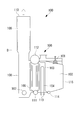
- the combustion gas generated by the combustion of the burner 101 passes from the furnace 102 through the superheater 104 and the evaporation tube group 105, similarly to the reheat boiler 100 having the conventional structure shown in FIG. 5.
- the main boiler 106 configured as described above, the reheating furnace 108 in which the combustion gas is reburned by the reheating burner 107, and the reburned combustion gas are configured to pass through the reheater 109.
- the combustion gas generated by the combustion of the burner 101 flows from the furnace 102 through the front bank tube 103, the superheater 104, and the evaporation tube group 105 in the main boiler 106. . Thereafter, the combustion gas flowing into the reheating furnace 108 from the main boiler 106 flows out to the reheater 109 together with the reheating combustion gas generated by the reheating burner 107.
- the gas obtained by mixing the combustion gas flowing in from the main boiler 106 and the reheat combustion gas generated in the reheat furnace 108 is collectively referred to, that is, the reheat furnace 108 and the downstream side.
- the gas flowing through is referred to as “mixed combustion gas”.
- the mixed combustion gas in which the combustion gas flowing in from the main boiler 106 and the reheat combustion gas generated in the reheat furnace 108 join together connects the reheat furnace 108 and the reheater 109 to form a flow path.
- the reheat furnace exit portion (which is also the inlet portion of the reheater 109) 120 is passed through.
- the reheating furnace outlet 120 is provided with a closing plate 130 in order to form a drift prevention portion for reducing the cross-sectional area of the mixed combustion gas. In this closing plate 130, the flow of the combustion gas that flows in from the main boiler 106 and changes its direction by approximately 90 degrees upward is combined with the flow of the reheat combustion gas that rises from below the reheat furnace 108, and is mixed.
- the closing plate 130 installed in a high temperature region where the high-temperature mixed combustion gas flows has a function of restricting the cross-sectional area of the mixed combustion gas at the reheater outlet 120 and temporarily reducing the cross-sectional area of the flow path temporarily. is doing.
- the closing plate 130 for reducing the cross-sectional area of the flow path
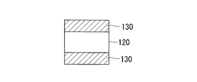
- FIG. 2A With respect to the channel cross-sectional area of the reheater outlet 120, the closing plate 130 is attached to the front and rear (front wall side and rear wall side) or the left and right (left wall side and right wall side) The channel is partially blocked, and the channel cross-sectional area is rapidly reduced.
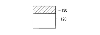
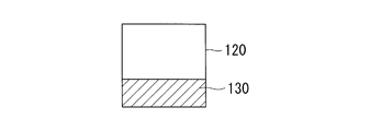
- the flow passage cross-sectional area of the reheater outlet 120 is either front and rear (front wall side and rear wall side) or left and right (left wall side and right wall side).
- a blocking plate 130 is attached to partially block the flow path, and the cross-sectional area of the flow path is rapidly reduced.
- a reheat furnace outlet portion that connects the reheat furnace 108 and the reheater 109 to form a flow path of mixed combustion gas (combustion gas and reheat combustion gas).
- combustion gas and reheat combustion gas mixed combustion gas
- the flow of the main combustion gas and the reheat combustion gas passing through the closing plate 130 is agitated by causing turbulence such as vortices due to a change in which the cross-sectional area of the flow path rapidly decreases. That is, the flow of the combustion gas whose direction has been changed by approximately 90 degrees upward and the flow of the reheat combustion gas that has risen upward are caused to collide with the closing plate 130, change in the flow direction and increase in flow velocity due to reduction in the cross-sectional area of the flow path.
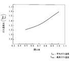
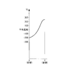
- FIG. 3 is a diagram illustrating the relationship between the opening ratio and the gas temperature ratio when the closing plate 130 is installed in the flow path cross-sectional area of the reheater outlet 120.
- the opening ratio on the horizontal axis is the ratio of the opening area where the flow passage cross-sectional area of the reheater outlet portion 120 remains without being blocked by the closing plate 130.
- the larger the numerical value the more the flow of the mixed combustion gas.
- the gas temperature ratio on the vertical axis is the ratio of the maximum gas temperature (Tmax) based on the average gas temperature (Tav). The closer the value is to 1, the more uniform the temperature is. That is, the larger the gas temperature ratio is, the wider the difference between the maximum gas temperature and the average gas temperature of the mixed combustion gas, and the temperature imbalance becomes larger.
- the gas temperature ratio approaches 1 as the aperture ratio decreases. Therefore, as the large block plate 130 is installed and the cross-sectional area of the flow path is reduced, stirring / mixing is promoted, and the temperature of the mixed combustion gas is Make uniform.
- the opening ratio of the reheater outlet 120 is reduced, the temperature imbalance of the mixed combustion gas is eliminated, but the pressure when the mixed combustion gas passes through the reheater outlet 120 having a small flow path cross-sectional area. The loss will increase. Therefore, the opening ratio of the reheater outlet 120 is changed in consideration of the temperature imbalance and pressure loss of the mixed combustion gas, and the size of the closing plate 130 (the sealed area of the flow path) is changed so as to obtain the best operating efficiency. And adjust as appropriate. In other words, by adopting a drift prevention portion formed by attaching the closing plate 130 to the reheat outlet opening 120, the size of the closing plate 130 can be changed to easily adjust the opening ratio of the channel cross-sectional area. can do.
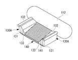
- the above-described closing plate 130 is installed on the stack tube group 140 passing through the reheating furnace outlet 120 as a closing plate 130A shown in FIG. 4 as a modified example of the above-described embodiment.
- the stack 140 is a tube group of evaporation tubes (stacks) 141 crossing the upper part of the reheating furnace 108.
- the closing plate 130A shown in FIG. 4 is divided into a plurality of sections so that the flow path cross-sectional area can be adjusted.
- the pair of left and right closing plates 130A are each divided into three. That is, one closing plate 130A is divided into three closing plate members 131, 132, and 133, and the closing plate members 131, 132, and 133 can be individually attached and detached. With such a configuration, the opening ratio of the channel cross-sectional area can be easily adjusted by changing the number of attachments and detachments on site.
- the number of the blocking plate members 131, 132, and 133 can be easily set to an optimum opening ratio based on the result (temperature unbalance level, etc.) of the combustion test performed at the site where the reheat boiler 10A is installed. It can be attached and detached to adjust. Note that the number of divisions of the closing plate 130A is not limited to the three divisions described above.
- the illustrated closing plate 130A is inclined so that the opening area on the outlet side gradually increases. For this reason, the mixed combustion gas having a uniform temperature distribution spreads smoothly into the reheater 109 and passes substantially uniformly throughout the entire interior of the reheater 109, improving the efficiency of heat exchange in the reheater 109. To do. Note that the improvement in the heat exchange efficiency of the reheater 109 is also effective in improving the efficiency of the reheat boiler 10A.
- the closing plate that narrows the flow path cross-sectional area to the reheat furnace outlet 120 that forms the flow path of the mixed combustion gas (combustion gas and reheat combustion gas). 130 is provided and a drift prevention part is provided, so that the flow of the mixed combustion gas that passes through the drift prevention part is disturbed to promote mixing, and the outlet side of the reheating furnace 108 that is downstream of the drift prevention part ( The temperature imbalance is reduced so that the temperature distribution becomes uniform at the reheater 109 inlet).
- the flow pattern of the combustion gas that becomes the mixed combustion gas and the reheat combustion gas can be changed by passing the mixed combustion gas through the drift prevention portion with the blocking plate 130 attached and narrowing the cross-sectional area of the flow path.
- the two combustion gases having different gas temperatures are mixed on the downstream side of the drift prevention unit, and flow into the reheater 109 in a state where the temperature distribution is substantially uniform.
- the imbalance of the mixed combustion gas temperature on the inlet side of the reheater 109 is eliminated, and an efficient reheat boiler 10A is provided by preventing or suppressing a decrease in heat transfer performance of the reheat furnace 108 and the reheater 109. can do. Furthermore, when the imbalance of the combustion gas temperature on the inlet side of the reheater 109 is eliminated, it is possible to prevent or suppress the reheat tube of the reheater 109 from being corroded at a high temperature. Further, when the imbalance of the combustion gas temperature on the inlet side of the reheater 109 is eliminated, the maximum gas temperature is also reduced, so that the strength reduction of the support material due to the high temperature can be prevented or suppressed. As a result, the reheat boiler 10A has improved durability and reliability. In addition, this invention is not limited to embodiment mentioned above, In the range which does not deviate from the summary, it can change suitably.
Landscapes
- Engineering & Computer Science (AREA)
- Mechanical Engineering (AREA)
- General Engineering & Computer Science (AREA)
- Physics & Mathematics (AREA)
- Thermal Sciences (AREA)
- Combustion Of Fluid Fuel (AREA)
Abstract
Description
また、従来の舶用ボイラにおいては、燃焼ガス後流側に再熱炉と再熱器とを備えた再熱ボイラが使用されている。
図5は、従来の再熱ボイラの構成を簡略に示す概略図である。図5に示すように、従来の再熱ボイラ100は、バーナ101、火炉102、フロントバンクチューブ103、過熱器(Superheater:SH)104及び蒸発管群(リアバンクチューブ)105からなる主ボイラ106と、蒸発管群105の後流側に再熱バーナ107を備えた再熱炉108と、排気ガス出口側に設けた再熱器109とからなる。
バーナ101の燃焼で発生した燃焼ガスは、火炉102からフロントバンクチューブ103、過熱器104及び蒸発管群105を流れ、再熱バーナ107の再熱燃焼ガスと再熱炉108にて混合した後、再熱器109と熱交換を行いながら流れ、ガス出口110から流出することで、効率的に運転を行うようにしていた。
なお、図5において、図中の符号111は水ドラム、112は蒸気ドラム、113,114はヘッダー、115はウォールチューブを示している。
このため、たとえば図6に示すように、再熱炉108の出口側(図5中の符号B部分)では、再熱炉108の前壁(図6中のX)側と後壁(図6中のY)側との間において、燃焼ガス温度に数百度の温度差が生じることがあるなど、燃焼ガス温度に生じる大きなアンバランスが問題となる。このような燃焼ガス温度のアンバランスは、主ボイラ106から流入する燃焼ガスと、再熱バーナ107の再熱燃焼ガスとの間に温度差があり、燃焼ガスと再熱燃焼ガスとが十分に混合されないためと考えられる。
本発明は、上記の問題に鑑みてなされたものであり、その目的とするところは、再熱炉の出口側における燃焼ガスのガス温度について、再熱バーナ内のガス流動パターンを変化させて温度分布のアンバランスを低減した再熱ボイラを提供することにある。
本発明の一態様に係る再熱ボイラは、バーナの燃焼で発生した主燃焼ガスが火炉から過熱器及び蒸発管群を通過して流れるように構成した主ボイラと、前記蒸発管群の後流側に配置され、再熱バーナの燃焼で再熱燃焼ガスを発生させる再熱炉と、該再熱炉の上部側に配置された再熱器とを備えている再熱ボイラであって、前記再熱炉と前記再熱器との間を連結して前記燃焼ガス及び前記再熱燃焼ガスの流路を形成する再熱炉出口部に、燃焼ガスの流路断面積を絞る偏流防止部を設けたものである。
この場合の塞ぎ板については、複数枚に分割して各々個別の着脱を可能にしたものが好ましく、これにより、現地における着脱枚数の変更により流路断面積の開口率を容易に調整できる。
すなわち、燃焼ガス及び再熱燃焼ガスが偏流防止部を通過することにより、燃焼ガス及び再熱燃焼ガスの流動パターンを変化させることができるため、ガス温度の異なる二つの燃焼ガスは偏流防止部の下流側で混合され、温度分布が略均一化された状態で再熱器に流入する。
本実施形態の再熱ボイラ10Aは、図5に示す従来構造の再熱ボイラ100と同様に、バーナ101の燃焼により発生した燃焼ガスが、火炉102から過熱器104、蒸発管群105を通過するように構成された主ボイラ106と、再熱バーナ107で燃焼ガスが再燃される再熱炉108と、再燃された燃焼ガスが、再熱器109を通過するように構成されている。
この塞ぎ板130は、主ボイラ106から流入して上向きに略90度の方向転換をする燃焼ガスの流れと、再熱炉108の下方から上昇する再熱燃焼ガスの流れとが合流し、混合燃焼ガスの流れとして再熱炉108から再熱器109へ向かう再熱器出口部120の流路断面積を絞ることで急変させている。すなわち、高温の混合燃焼ガスが流れる高温領域に設置される塞ぎ板130は、混合燃焼ガスの流路断面積を再熱器出口120で絞り、流路断面積を一時的に急減させる機能を有している。
図2Aに示す設置例では、再熱器出口部120の流路断面積について、前後(前壁側及び後壁側)または左右(左壁側及び右壁側)に塞ぎ板130を取り付け、流路を部分的に塞いで流路断面積を急激に減少させている。
図2B,図2Cに示す設置例では、再熱器出口部120の流路断面積について、前後(前壁側及び後壁側)または左右(左壁側及び右壁側)のいずれか一方に塞ぎ板130を取り付け、流路を部分的に塞いで流路断面積を急激に減少させている。
この結果、異なる温度を有する混合燃焼ガスの二つの流れは、塞ぎ板130を通過することにより全体が略均一化した温度の流れとなって再熱器109へ流入する。
この図において、横軸の開口率は、再熱器出口部120の流路断面積が塞ぎ板130により塞がれることなく残った開口面積の割合であり、数値が大きいほど混合燃焼ガスの流路となる開口面積は大きくなる。
一方、縦軸のガス温度比は、平均ガス温度(Tav)を基準とした最高ガス温度(Tmax)の比であり、数値が1に近いほど均一化した温度となる。すなわち、ガス温度比が大きい値になればなるほど混合燃焼ガスの最高ガス温度と平均ガス温度との差は広がり、温度アンバランスが大きくなっている。
このような塞ぎ板130Aの設置構造を採用すると、混合燃焼ガスが流れる高温領域に新たなサポート部材(突起部材)を設ける必要がない。なお、高温領域に取り付けるサポート部材は、高温の環境に耐える高級な素材を使用する必要がある。
このような構成とすれば、現地における着脱枚数の変更により流路断面積の開口率を容易に調整できる。すなわち、塞ぎ板部材131,132,133の設置数については、再熱ボイラ10Aを設置した現地で燃焼試験をした結果(温度アンバランスレベル等)に基づいて、最適な開口率となるように容易に着脱して調整することができる。なお、塞ぎ板130Aの分割数については、上述した3分割に限定されることはない。
さらに、再熱器109の入口側における燃焼ガス温度のアンバランスが解消されると、再熱器109の再熱チューブが高温腐食することを防止または抑制できる。また、再熱器109の入口側における燃焼ガス温度のアンバランスが解消されると、最高ガス温度も低下するので、高温によるサポート材の強度低下についても防止または抑制できる。この結果、再熱ボイラ10Aは、耐久性や信頼性が向上することとなる。
なお、本発明は上述した実施形態に限定されることはなく、その要旨を逸脱しない範囲内において適宜変更することができる。
101 バーナ
102 火炉
103 フロントバンクチューブ
104 過熱器(SH)
105 蒸発管群(リアバンクチューブ)
106 主ボイラ
107 再熱バーナ
108 再熱炉
109 再熱器
110 ガス出口
111 水ドラム
112 蒸気ドラム
120 再熱炉出口部
130,130A 塞ぎ板
131,132,133 塞ぎ板部材
140 スタック管群
141 蒸発管(スタック)
Claims (3)
- バーナの燃焼で発生した主燃焼ガスが火炉から過熱器及び蒸発管群を通過して流れるように構成した主ボイラと、前記蒸発管群の後流側に配置され、再熱バーナの燃焼で再熱燃焼ガスを発生させる再熱炉と、該再熱炉の上部側に配置された再熱器とを備えている再熱ボイラであって、
前記再熱炉と前記再熱器との間を連結して前記燃焼ガス及び前記再熱燃焼ガスの流路を形成する再熱炉出口部に、燃焼ガスの流路断面積を絞る偏流防止部を設けた再熱ボイラ。 - 前記偏流防止部が前記再熱炉出口部に塞ぎ板を取り付けて形成されている請求項1に記載の再熱ボイラ。
- 前記塞ぎ板を複数枚に分割して各々個別の着脱が可能である請求項2に記載の再熱ボイラ。
Priority Applications (4)
| Application Number | Priority Date | Filing Date | Title |
|---|---|---|---|
| US13/058,052 US20110139092A1 (en) | 2008-09-17 | 2009-08-26 | Reheat boiler |
| EP09814438.9A EP2325560B1 (en) | 2008-09-17 | 2009-08-26 | Reheat boiler |
| CN2009801330148A CN102132095B (zh) | 2008-09-17 | 2009-08-26 | 再热锅炉 |
| KR1020117004050A KR101280130B1 (ko) | 2008-09-17 | 2009-08-26 | 재열 보일러 |
Applications Claiming Priority (2)
| Application Number | Priority Date | Filing Date | Title |
|---|---|---|---|
| JP2008237711A JP5148426B2 (ja) | 2008-09-17 | 2008-09-17 | 再熱ボイラ |
| JP2008-237711 | 2008-09-17 |
Publications (1)
| Publication Number | Publication Date |
|---|---|
| WO2010032593A1 true WO2010032593A1 (ja) | 2010-03-25 |
Family
ID=42039431
Family Applications (1)
| Application Number | Title | Priority Date | Filing Date |
|---|---|---|---|
| PCT/JP2009/064880 Ceased WO2010032593A1 (ja) | 2008-09-17 | 2009-08-26 | 再熱ボイラ |
Country Status (6)
| Country | Link |
|---|---|
| US (1) | US20110139092A1 (ja) |
| EP (1) | EP2325560B1 (ja) |
| JP (1) | JP5148426B2 (ja) |
| KR (1) | KR101280130B1 (ja) |
| CN (1) | CN102132095B (ja) |
| WO (1) | WO2010032593A1 (ja) |
Families Citing this family (4)
| Publication number | Priority date | Publication date | Assignee | Title |
|---|---|---|---|---|
| JP5010425B2 (ja) * | 2007-10-17 | 2012-08-29 | 三菱重工業株式会社 | 再熱ボイラ及び再熱ボイラのガス温度制御方法 |
| CN103742209A (zh) * | 2013-08-21 | 2014-04-23 | 王强 | 可演化分级热焓加热锅炉技术 |
| CN103776020B (zh) * | 2014-02-26 | 2015-06-17 | 章礼道 | 尾部三烟道双挡板加射流烟气再循环二次再热电站锅炉 |
| KR102681525B1 (ko) | 2023-04-21 | 2024-07-04 | 에이에스티 주식회사 | 열효율 개선 및 증발관 점검 기능을 갖는 수관식 보일러 |
Citations (5)
| Publication number | Priority date | Publication date | Assignee | Title |
|---|---|---|---|---|
| JPS5189236A (ja) * | 1975-02-03 | 1976-08-04 | ||
| JPS51148862A (en) * | 1975-06-14 | 1976-12-21 | Babcock Hitachi Kk | Gas mixing apparatus |
| JPS5367001A (en) * | 1976-11-26 | 1978-06-15 | Mitsubishi Heavy Ind Ltd | Reheating boiler |
| JPS61101233A (ja) * | 1984-10-22 | 1986-05-20 | Mitsubishi Heavy Ind Ltd | 燃焼処理装置 |
| JP2002243106A (ja) | 2001-02-21 | 2002-08-28 | Mitsubishi Heavy Ind Ltd | ボイラ |
Family Cites Families (26)
| Publication number | Priority date | Publication date | Assignee | Title |
|---|---|---|---|---|
| CH358096A (de) * | 1958-03-12 | 1961-11-15 | Sulzer Ag | Verfahren zur Regelung der Ausgangstemperaturen an Überhitzern einer Dampferzeugeranlage und Einrichtung zur Ausübung des Verfahrens |
| FR1467878A (fr) * | 1960-11-21 | 1967-02-03 | Appareil distributeur-allumeur de cigarettes destiné à l'équipement des véhicules automobiles | |
| US3301224A (en) * | 1965-12-13 | 1967-01-31 | Combustion Eng | Steam generator organization |
| US3446939A (en) * | 1966-09-08 | 1969-05-27 | Patterson Kelley Co | Electric immersion water heater |
| GB1265662A (ja) * | 1968-09-23 | 1972-03-01 | ||
| US3956898A (en) * | 1974-12-20 | 1976-05-18 | Combustion Engineering, Inc. | Marine vapor generator having low temperature reheater |
| US4438625A (en) * | 1978-10-26 | 1984-03-27 | Rice Ivan G | Reheat gas turbine combined with steam turbine |
| US4272953A (en) * | 1978-10-26 | 1981-06-16 | Rice Ivan G | Reheat gas turbine combined with steam turbine |
| US4479458A (en) * | 1983-10-03 | 1984-10-30 | Foster Wheeler Energy Corporation | Hexagonal pressurized fluidized bed reactor |
| JPS61191803A (ja) * | 1985-02-20 | 1986-08-26 | 三菱重工業株式会社 | ボイラ |
| US4955190A (en) * | 1988-03-10 | 1990-09-11 | Foster Wheeler Development Corporation | Method for driving a gas turbine utilizing a hexagonal pressurized fluidized bed reactor |
| CN2156395Y (zh) * | 1993-06-30 | 1994-02-16 | 华北电力学院北京研究生部 | 锅炉燃烧导流装置 |
| US5355843A (en) * | 1993-07-12 | 1994-10-18 | University Of Chicago | Heat transfer mechanism with thin filaments including ceramic high temperature heat exchanger |
| US5628183A (en) * | 1994-10-12 | 1997-05-13 | Rice; Ivan G. | Split stream boiler for combined cycle power plants |
| JP3794796B2 (ja) * | 1997-08-29 | 2006-07-12 | 三菱重工業株式会社 | コンバインド発電プラント |
| US6035642A (en) * | 1999-01-13 | 2000-03-14 | Combustion Engineering, Inc. | Refurbishing conventional power plants for Kalina cycle operation |
| US6105369A (en) * | 1999-01-13 | 2000-08-22 | Abb Alstom Power Inc. | Hybrid dual cycle vapor generation |
| US6253552B1 (en) * | 1999-01-13 | 2001-07-03 | Abb Combustion Engineering | Fluidized bed for kalina cycle power generation system |
| US6325002B1 (en) * | 1999-02-03 | 2001-12-04 | Clearstack Combustion Corporation | Low nitrogen oxides emissions using three stages of fuel oxidation and in-situ furnace flue gas recirculation |
| US6699029B2 (en) * | 2001-01-11 | 2004-03-02 | Praxair Technology, Inc. | Oxygen enhanced switching to combustion of lower rank fuels |
| US6604474B2 (en) * | 2001-05-11 | 2003-08-12 | General Electric Company | Minimization of NOx emissions and carbon loss in solid fuel combustion |
| US6619041B2 (en) * | 2001-06-29 | 2003-09-16 | L'air Liquide - Societe Anonyme A Directoire Et Conseil De Surveillance Pour L'etude Et L'exploitation Des Procedes Georges Claude | Steam generation apparatus and methods |
| US7708964B2 (en) * | 2004-12-02 | 2010-05-04 | Battelle Energy Alliance, Llc | Oil shale derived pollutant control materials and methods and apparatuses for producing and utilizing the same |
| EP1677578A1 (en) * | 2004-12-30 | 2006-07-05 | Walter Niemetz | Installation for reheating portioned chilled or frozen snack food products |
| US7531153B2 (en) * | 2007-03-27 | 2009-05-12 | General Electric Company | Methods and apparatus for removing mercury from combustion flue gas |
| US7504081B2 (en) * | 2007-03-27 | 2009-03-17 | General Electric Company | Methods and apparatus to facilitate reducing mercury emissions |
-
2008
- 2008-09-17 JP JP2008237711A patent/JP5148426B2/ja active Active
-
2009
- 2009-08-26 EP EP09814438.9A patent/EP2325560B1/en active Active
- 2009-08-26 WO PCT/JP2009/064880 patent/WO2010032593A1/ja not_active Ceased
- 2009-08-26 CN CN2009801330148A patent/CN102132095B/zh active Active
- 2009-08-26 KR KR1020117004050A patent/KR101280130B1/ko active Active
- 2009-08-26 US US13/058,052 patent/US20110139092A1/en not_active Abandoned
Patent Citations (5)
| Publication number | Priority date | Publication date | Assignee | Title |
|---|---|---|---|---|
| JPS5189236A (ja) * | 1975-02-03 | 1976-08-04 | ||
| JPS51148862A (en) * | 1975-06-14 | 1976-12-21 | Babcock Hitachi Kk | Gas mixing apparatus |
| JPS5367001A (en) * | 1976-11-26 | 1978-06-15 | Mitsubishi Heavy Ind Ltd | Reheating boiler |
| JPS61101233A (ja) * | 1984-10-22 | 1986-05-20 | Mitsubishi Heavy Ind Ltd | 燃焼処理装置 |
| JP2002243106A (ja) | 2001-02-21 | 2002-08-28 | Mitsubishi Heavy Ind Ltd | ボイラ |
Also Published As
| Publication number | Publication date |
|---|---|
| KR20110043710A (ko) | 2011-04-27 |
| US20110139092A1 (en) | 2011-06-16 |
| EP2325560B1 (en) | 2018-06-20 |
| CN102132095B (zh) | 2013-11-06 |
| KR101280130B1 (ko) | 2013-06-28 |
| EP2325560A4 (en) | 2016-10-26 |
| JP2010071513A (ja) | 2010-04-02 |
| EP2325560A1 (en) | 2011-05-25 |
| CN102132095A (zh) | 2011-07-20 |
| JP5148426B2 (ja) | 2013-02-20 |
Similar Documents
| Publication | Publication Date | Title |
|---|---|---|
| JP5896644B2 (ja) | バーナ装置を稼働させる方法及びこの方法を実施するバーナ装置 | |
| US10890356B2 (en) | Heat exchange device and heat source machine | |
| JP2632635B2 (ja) | 水管群を有するボイラの燃焼装置と該燃焼装置を使用するボイラの燃焼方法 | |
| JP5148426B2 (ja) | 再熱ボイラ | |
| CN101883951B (zh) | 船用锅炉构造 | |
| JP2002535587A (ja) | 化石燃料ボイラ | |
| US20110162592A1 (en) | Continuous steam generator | |
| US9671105B2 (en) | Continuous flow steam generator with a two-pass boiler design | |
| JP5611702B2 (ja) | ゲート弁装置ならびにそれを備えた蒸気取り扱い装置 | |
| JP2011021768A (ja) | ボイラ | |
| JP7105707B2 (ja) | アフタエアポート及びこれを備えた燃焼装置 | |
| JP5010425B2 (ja) | 再熱ボイラ及び再熱ボイラのガス温度制御方法 | |
| JP2937988B1 (ja) | 熱交換器 | |
| JP2005147426A (ja) | 熱交換器 | |
| JP5302852B2 (ja) | 再熱ボイラ | |
| JP2019007629A (ja) | ボイラ装置 | |
| JP2019203661A (ja) | ボイラ装置及び過熱器 | |
| JP6833345B2 (ja) | 熱交換装置及び熱交換装置におけるバッフルプレートの設置範囲設定方法 | |
| JP2017194223A (ja) | 熱交換装置 | |
| JP2007187356A (ja) | 燃焼炉とボイラ装置 | |
| JP6113632B2 (ja) | ボイラシステム | |
| CN112944383A (zh) | 旋流燃烧器及其系统 | |
| JP2008076020A (ja) | 貫流式排熱回収ボイラ | |
| JPH11132403A (ja) | 多管式水管ボイラ | |
| JP2005016827A (ja) | ボイラ |
Legal Events
| Date | Code | Title | Description |
|---|---|---|---|
| WWE | Wipo information: entry into national phase |
Ref document number: 200980133014.8 Country of ref document: CN |
|
| 121 | Ep: the epo has been informed by wipo that ep was designated in this application |
Ref document number: 09814438 Country of ref document: EP Kind code of ref document: A1 |
|
| WWE | Wipo information: entry into national phase |
Ref document number: 2009814438 Country of ref document: EP |
|
| ENP | Entry into the national phase |
Ref document number: 20117004050 Country of ref document: KR Kind code of ref document: A |
|
| WWE | Wipo information: entry into national phase |
Ref document number: 13058052 Country of ref document: US |
|
| NENP | Non-entry into the national phase |
Ref country code: DE |