WO2010032666A1 - 車両の制御装置 - Google Patents
車両の制御装置 Download PDFInfo
- Publication number
- WO2010032666A1 WO2010032666A1 PCT/JP2009/065786 JP2009065786W WO2010032666A1 WO 2010032666 A1 WO2010032666 A1 WO 2010032666A1 JP 2009065786 W JP2009065786 W JP 2009065786W WO 2010032666 A1 WO2010032666 A1 WO 2010032666A1
- Authority
- WO
- WIPO (PCT)
- Prior art keywords
- driving force
- operation mode
- force parameter
- required driving
- target value
- Prior art date
- Legal status (The legal status is an assumption and is not a legal conclusion. Google has not performed a legal analysis and makes no representation as to the accuracy of the status listed.)
- Ceased
Links
Images



Classifications
-
- B—PERFORMING OPERATIONS; TRANSPORTING
- B60—VEHICLES IN GENERAL
- B60W—CONJOINT CONTROL OF VEHICLE SUB-UNITS OF DIFFERENT TYPE OR DIFFERENT FUNCTION; CONTROL SYSTEMS SPECIALLY ADAPTED FOR HYBRID VEHICLES; ROAD VEHICLE DRIVE CONTROL SYSTEMS FOR PURPOSES NOT RELATED TO THE CONTROL OF A PARTICULAR SUB-UNIT
- B60W50/00—Details of control systems for road vehicle drive control not related to the control of a particular sub-unit, e.g. process diagnostic or vehicle driver interfaces
- B60W50/08—Interaction between the driver and the control system
- B60W50/082—Selecting or switching between different modes of propelling
-
- B—PERFORMING OPERATIONS; TRANSPORTING
- B60—VEHICLES IN GENERAL
- B60W—CONJOINT CONTROL OF VEHICLE SUB-UNITS OF DIFFERENT TYPE OR DIFFERENT FUNCTION; CONTROL SYSTEMS SPECIALLY ADAPTED FOR HYBRID VEHICLES; ROAD VEHICLE DRIVE CONTROL SYSTEMS FOR PURPOSES NOT RELATED TO THE CONTROL OF A PARTICULAR SUB-UNIT
- B60W10/00—Conjoint control of vehicle sub-units of different type or different function
- B60W10/04—Conjoint control of vehicle sub-units of different type or different function including control of propulsion units
- B60W10/06—Conjoint control of vehicle sub-units of different type or different function including control of propulsion units including control of combustion engines
-
- B—PERFORMING OPERATIONS; TRANSPORTING
- B60—VEHICLES IN GENERAL
- B60W—CONJOINT CONTROL OF VEHICLE SUB-UNITS OF DIFFERENT TYPE OR DIFFERENT FUNCTION; CONTROL SYSTEMS SPECIALLY ADAPTED FOR HYBRID VEHICLES; ROAD VEHICLE DRIVE CONTROL SYSTEMS FOR PURPOSES NOT RELATED TO THE CONTROL OF A PARTICULAR SUB-UNIT
- B60W10/00—Conjoint control of vehicle sub-units of different type or different function
- B60W10/10—Conjoint control of vehicle sub-units of different type or different function including control of change-speed gearings
- B60W10/101—Infinitely variable gearings
-
- B—PERFORMING OPERATIONS; TRANSPORTING
- B60—VEHICLES IN GENERAL
- B60W—CONJOINT CONTROL OF VEHICLE SUB-UNITS OF DIFFERENT TYPE OR DIFFERENT FUNCTION; CONTROL SYSTEMS SPECIALLY ADAPTED FOR HYBRID VEHICLES; ROAD VEHICLE DRIVE CONTROL SYSTEMS FOR PURPOSES NOT RELATED TO THE CONTROL OF A PARTICULAR SUB-UNIT
- B60W30/00—Purposes of road vehicle drive control systems not related to the control of a particular sub-unit, e.g. of systems using conjoint control of vehicle sub-units
- B60W30/18—Propelling the vehicle
- B60W30/188—Controlling power parameters of the driveline, e.g. determining the required power
-
- F—MECHANICAL ENGINEERING; LIGHTING; HEATING; WEAPONS; BLASTING
- F02—COMBUSTION ENGINES; HOT-GAS OR COMBUSTION-PRODUCT ENGINE PLANTS
- F02D—CONTROLLING COMBUSTION ENGINES
- F02D29/00—Controlling engines, such controlling being peculiar to the devices driven thereby, the devices being other than parts or accessories essential to engine operation, e.g. controlling of engines by signals external thereto
- F02D29/02—Controlling engines, such controlling being peculiar to the devices driven thereby, the devices being other than parts or accessories essential to engine operation, e.g. controlling of engines by signals external thereto peculiar to engines driving vehicles; peculiar to engines driving variable pitch propellers
-
- B—PERFORMING OPERATIONS; TRANSPORTING
- B60—VEHICLES IN GENERAL
- B60W—CONJOINT CONTROL OF VEHICLE SUB-UNITS OF DIFFERENT TYPE OR DIFFERENT FUNCTION; CONTROL SYSTEMS SPECIALLY ADAPTED FOR HYBRID VEHICLES; ROAD VEHICLE DRIVE CONTROL SYSTEMS FOR PURPOSES NOT RELATED TO THE CONTROL OF A PARTICULAR SUB-UNIT
- B60W2540/00—Input parameters relating to occupants
- B60W2540/10—Accelerator pedal position
-
- B—PERFORMING OPERATIONS; TRANSPORTING
- B60—VEHICLES IN GENERAL
- B60W—CONJOINT CONTROL OF VEHICLE SUB-UNITS OF DIFFERENT TYPE OR DIFFERENT FUNCTION; CONTROL SYSTEMS SPECIALLY ADAPTED FOR HYBRID VEHICLES; ROAD VEHICLE DRIVE CONTROL SYSTEMS FOR PURPOSES NOT RELATED TO THE CONTROL OF A PARTICULAR SUB-UNIT
- B60W2710/00—Output or target parameters relating to a particular sub-units
- B60W2710/06—Combustion engines, Gas turbines
- B60W2710/0644—Engine speed
-
- B—PERFORMING OPERATIONS; TRANSPORTING
- B60—VEHICLES IN GENERAL
- B60W—CONJOINT CONTROL OF VEHICLE SUB-UNITS OF DIFFERENT TYPE OR DIFFERENT FUNCTION; CONTROL SYSTEMS SPECIALLY ADAPTED FOR HYBRID VEHICLES; ROAD VEHICLE DRIVE CONTROL SYSTEMS FOR PURPOSES NOT RELATED TO THE CONTROL OF A PARTICULAR SUB-UNIT
- B60W2710/00—Output or target parameters relating to a particular sub-units
- B60W2710/10—Change speed gearings
- B60W2710/105—Output torque
-
- F—MECHANICAL ENGINEERING; LIGHTING; HEATING; WEAPONS; BLASTING
- F02—COMBUSTION ENGINES; HOT-GAS OR COMBUSTION-PRODUCT ENGINE PLANTS
- F02D—CONTROLLING COMBUSTION ENGINES
- F02D13/00—Controlling the engine output power by varying inlet or exhaust valve operating characteristics, e.g. timing
- F02D13/02—Controlling the engine output power by varying inlet or exhaust valve operating characteristics, e.g. timing during engine operation
- F02D13/0203—Variable control of intake and exhaust valves
- F02D13/0207—Variable control of intake and exhaust valves changing valve lift or valve lift and timing
-
- F—MECHANICAL ENGINEERING; LIGHTING; HEATING; WEAPONS; BLASTING
- F16—ENGINEERING ELEMENTS AND UNITS; GENERAL MEASURES FOR PRODUCING AND MAINTAINING EFFECTIVE FUNCTIONING OF MACHINES OR INSTALLATIONS; THERMAL INSULATION IN GENERAL
- F16H—GEARING
- F16H61/00—Control functions within control units of change-speed- or reversing-gearings for conveying rotary motion ; Control of exclusively fluid gearing, friction gearing, gearings with endless flexible members or other particular types of gearing
- F16H61/66—Control functions within control units of change-speed- or reversing-gearings for conveying rotary motion ; Control of exclusively fluid gearing, friction gearing, gearings with endless flexible members or other particular types of gearing specially adapted for continuously variable gearings
-
- Y—GENERAL TAGGING OF NEW TECHNOLOGICAL DEVELOPMENTS; GENERAL TAGGING OF CROSS-SECTIONAL TECHNOLOGIES SPANNING OVER SEVERAL SECTIONS OF THE IPC; TECHNICAL SUBJECTS COVERED BY FORMER USPC CROSS-REFERENCE ART COLLECTIONS [XRACs] AND DIGESTS
- Y02—TECHNOLOGIES OR APPLICATIONS FOR MITIGATION OR ADAPTATION AGAINST CLIMATE CHANGE
- Y02T—CLIMATE CHANGE MITIGATION TECHNOLOGIES RELATED TO TRANSPORTATION
- Y02T10/00—Road transport of goods or passengers
- Y02T10/80—Technologies aiming to reduce greenhouse gasses emissions common to all road transportation technologies
- Y02T10/84—Data processing systems or methods, management, administration
Definitions
- the present invention relates to a control device for a vehicle mounted with a continuously variable transmission and driven by an internal combustion engine, and more particularly to a control device for a vehicle capable of switching an operation mode intended to reduce a fuel consumption rate.
- Patent Document 1 discloses a vehicle control device including a continuously variable transmission. According to this control device, an engine output (work rate) corresponding to an accelerator pedal operation amount is reduced to a minimum fuel consumption rate. The target engine speed for realization is calculated, and the speed ratio of the continuously variable transmission is controlled so that the actual engine speed matches the target engine speed.
- Patent Document 1 when the speed ratio of the continuously variable transmission is controlled so as to perform the minimum fuel consumption rate operation, the acceleration response of the engine intended by the driver when the accelerator pedal is depressed rapidly is obtained. Since there is a problem that cannot be obtained, Patent Document 2 discloses a technique for solving this problem.
- Patent Document 2 discloses that the shift control is performed so that the minimum fuel consumption rate operation is performed when the engine operation state is steady, while the target engine output according to the accelerator pedal operation amount, the actual engine output, When the difference is large, control is performed to shift from the minimum fuel consumption rate operation to an operation that provides good acceleration response.
- Patent Document 3 discloses a control device that calculates the target throttle valve opening from the accelerator pedal operation amount and controls the actual throttle valve opening to coincide with the target throttle valve opening.
- a plurality of conversion tables having different conversion characteristics for calculating the target throttle valve opening from the accelerator pedal operation amount are provided, and the conversion table is selected according to the setting of the operation mode switch.
- driving with reduced fuel consumption rate and driving with an emphasis on acceleration response can be performed according to the driver's selection according to the setting of the driving mode switch.
- the driver cannot maintain the accelerator pedal operation amount in a constant state, but performs an operation that changes it smallly (hereinafter referred to as “butter foot operation”), and the engine operation deviates from the minimum fuel consumption rate operation, and the fuel consumption rate is reduced. It sometimes made it worse.
- the present invention has been made paying attention to this point.
- the engine output is appropriately controlled in accordance with the amount of operation of the accelerator pedal, and the fuel consumption rate is deteriorated even in the case where the accelerator pedal is operated by the butterfly. It is an object of the present invention to provide a vehicle control device that can suppress the above.
- the present invention provides a control device for a vehicle which is equipped with a continuously variable transmission (20) and is driven by the internal combustion engine (1) via the continuously variable transmission (20).
- the control device includes a driving force parameter setting means, a driving force control means (3), a target value setting means, a driving means, a target rotational speed setting means, a shift control means, an operation mode switch (15), It has.
- the driving force parameter setting means sets a required driving force parameter (APREQ) indicating a required driving force of the engine based on an operation amount (AP) of an accelerator pedal of the vehicle.
- the driving force control means controls the driving force of the engine, and the target value setting means is a target value (THCMD) of a control amount (TH) of the driving force control means based on the required driving force parameter (APREQ). ) Is set.
- the driving means drives the driving force control means (3) so that the control amount (TH) matches the target value (THCMD).
- the target speed setting means sets the target speed (NEOBJ) of the engine based on the required driving force parameter (APREQ).
- the shift control means controls the continuously variable transmission (20) such that the engine speed (NE) is equal to the target speed (NEOBJ).
- the operation mode switch is provided to switch at least between the first operation mode (normal operation mode or sports operation mode) and the second operation mode (eco operation mode) in which the fuel consumption rate is lower than that of the first operation mode. It has been.
- the driving force parameter setting means is configured to output the required driving force parameter (AP) corresponding to the operation amount (AP) of the accelerator pedal.
- APREQ is set to a value smaller than that in the first operation mode.
- the target value setting means is preset according to the engine speed (NE) and the required driving force parameter (APREQ) when the second operation mode (eco-operation mode) is designated by the operation mode switch.
- the second characteristic switching means for calculating the target value (THCMD), and the first predetermined characteristic (THBE map) includes the required driving force parameter ( In the first predetermined range (RCST1) of APREQ), the target value (THCMD) corresponding to the same engine speed (NE) is set to be constant.
- the required driving force parameter is set based on the operation amount of the accelerator pedal of the vehicle
- the target value of the control amount of the driving force control means is set based on the required driving force parameter
- the driving force control means is driven so that the control amount matches the target value.
- the target engine speed is set based on the required driving force parameter, and the continuously variable transmission is controlled so that the engine speed becomes the target engine speed.
- the target value of the control amount is calculated based on the first predetermined characteristic set in advance according to the engine speed and the required driving force parameter.
- the first predetermined characteristic is set so that the target value corresponding to the same engine speed is constant in the first predetermined range of the required driving force parameter, so that the change in the accelerator pedal operation amount accompanying the butterfly operation is changed. Even if the target driving force parameter is within the first predetermined range, the target value is held substantially constant. Therefore, even when the accelerator pedal is operated by a butterfly, the fuel consumption rate can be prevented from deteriorating.
- the second characteristic switching means responds to the engine speed (NE) and the required driving force parameter (APREQ) when the first operation mode (normal operation mode) is designated by the operation mode switch.
- the target value (THCMD map) is calculated based on a preset second predetermined characteristic (THBN map), and the second predetermined characteristic (THBN map) is a second predetermined range (APREQ) of the required driving force parameter (APREQ).
- THBN map a preset second predetermined characteristic
- THBN map second predetermined characteristic of the required driving force parameter
- RCST2 the target value (THCMD) corresponding to the same engine speed (NE) is set to be constant, and the second predetermined range (RCST2) is greater than the first predetermined range (RCST1). Narrow is desirable.
- the control amount target is set based on the second predetermined characteristic set in advance according to the engine speed and the required driving force parameter. A value is calculated.
- the second predetermined characteristic is set such that a target value corresponding to the same engine speed is constant in the second predetermined range of the required driving force parameter, and the second predetermined range is narrower than the first predetermined range. Is set. Therefore, in the first operation mode, the range in which the target value changes in response to changes in the accelerator pedal operation amount is widened, and acceleration response can be improved compared to the second operation mode.
- the second characteristic switching means is a third predetermined value preset according to the required driving force parameter (APREQ) when the first driving mode (sport driving mode) is designated by the driving mode switch.
- the target value (THCMD) is calculated based on a characteristic (THBS table), and the target value (THCMD) is unambiguous in the third predetermined characteristic (THBS table) corresponding to the required driving force parameter (APREQ). It is desirable that the target value (THCMD) increases as the required driving force parameter (APREQ) increases.
- the target value of the control amount is calculated based on the third predetermined characteristic set in advance according to the required driving force parameter.
- the third predetermined characteristic is set so that the target value is uniquely determined corresponding to the required driving force parameter, and the target value increases as the required driving force parameter increases. Therefore, in the first operation mode, The target value changes corresponding to the change in the accelerator pedal operation amount, and the acceleration response can be improved compared to the second operation mode.
- the shift control means designates the first operation mode (normal operation mode or sport operation mode). It is desirable to slow down the speed change response speed of the continuously variable transmission from time to time.
- the speed change response speed of the continuously variable transmission is controlled to be slower than when the first operation mode is designated. It is possible to reliably prevent the fuel consumption rate from deteriorating when the pedal is operated by the pedal.
- FIG. 1 is a diagram showing a configuration of an internal combustion engine and a continuously variable transmission mounted on a vehicle according to an embodiment of the present invention, and a control device thereof.
- 3 is a flowchart for explaining the overall configuration of throttle valve opening control of an internal combustion engine and shift control of a continuously variable transmission. It is a flowchart of the process which calculates a required driving force parameter (APREQ). It is a figure which shows the map referred by the process of FIG. It is a flowchart of a throttle valve opening control process. It is a figure which shows the map and table referred by the process of FIG.
- APIQ required driving force parameter
- FIG. 1 is a diagram showing a configuration of an internal combustion engine and a continuously variable transmission mounted on a vehicle according to an embodiment of the present invention, and control devices thereof.
- a throttle valve 3 is disposed in the middle of an intake pipe 2 of an internal combustion engine (hereinafter simply referred to as “engine”) 1.
- the throttle valve 3 is provided with a throttle valve opening sensor 4 for detecting the opening TH of the throttle valve 3, and a detection signal thereof is supplied to an electronic control unit (hereinafter referred to as “ECU”) 5.
- ECU electronice control unit
- An actuator 11 that drives the throttle valve 3 is connected to the throttle valve 3, and the operation of the actuator 11 is controlled by the ECU 5.
- the fuel injection valve 6 is provided for each cylinder slightly upstream of the intake valve, and each injection valve is connected to a fuel pump (not shown) and electrically connected to the ECU 5, and the fuel from the ECU 5 The valve opening time and valve opening timing of the injection valve 6 are controlled.
- the ECU 5 detects an engine rotational speed sensor 12 that detects the rotational speed (rotational speed) NE of the engine 1, and an accelerator pedal depression amount (hereinafter referred to as “accelerator pedal operation amount”) AP that is driven by the engine 1.
- An accelerator sensor 13, a vehicle speed sensor 14 for detecting the vehicle speed (traveling speed) VP of the vehicle, and an operation mode switch 15 for setting a vehicle operation mode by the driver are connected. Detection signals and switches of these sensors A signal indicating the setting is supplied to the ECU 5.
- a low fuel consumption rate operation mode (hereinafter referred to as “eco driving mode”) for suppressing the fuel consumption rate, a sports operation mode in which acceleration response of the engine 1 is given priority over suppression of the fuel consumption rate, and low Three operation modes of a normal operation mode, which is an operation mode having an intermediate characteristic between the fuel consumption rate operation mode and the sport operation mode, can be selected.
- Sensors such as an engine coolant temperature sensor, an intake air temperature sensor, and an intake pressure sensor (not shown) are also connected to the ECU 5.
- the output shaft of the engine 1 is connected to a continuously variable transmission (hereinafter referred to as “CVT”) 20, and the output shaft of the CVT 20 drives the drive wheels of the vehicle via a drive mechanism.
- CVT 20 is connected to the ECU 5, and shift control is performed by the ECU 5.
- the ECU 5 shapes an input signal waveform from the above-described sensor, corrects the voltage level to a predetermined level, converts an analog signal value into a digital signal value, a central processing circuit (hereinafter referred to as “CPU”). ”), A storage circuit for storing various calculation programs executed by the CPU, calculation results, and the like, an actuator 11, the fuel injection valve 6, and an output circuit for supplying drive signals to the CVT 20.
- CPU central processing circuit
- the ECU 5 calculates the target opening THCMD of the throttle valve 3 according to the accelerator pedal operation amount AP, the vehicle speed VP, the setting of the operation mode switch 15, and the like, and the detected throttle valve opening TH coincides with the target opening THCMD. Thus, the actuator 11 is driven. Further, the ECU 5 calculates the target engine speed NEOBJ according to the accelerator pedal operation amount AP, the vehicle speed VP, the setting of the operation mode switch 15, and the like, and shifts the CVT 20 so that the engine speed NE matches the target engine speed NEOBJ. Take control.
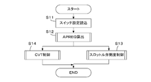
- FIG. 2 is a flowchart for explaining the overall configuration of throttle valve opening control and CVT control by the ECU 5.
- step S11 the setting of the operation mode switch 15 is read, and in step S12, the APREQ calculation process shown in FIG. 3 is executed to calculate the required driving force parameter APREQ.
- step S13 throttle valve opening control is performed based on the required driving force parameter APREQ calculated in step S12, while in step S14, CVT control is performed based on the required driving force parameter APREQ.
- the target engine speed NEOBJ is set according to the required driving force parameter APREQ, and the shift control is performed so that the engine speed NE matches the target engine speed NEOBJ.
- the target engine speed NEOBJ is set so that the minimum fuel consumption rate operation is realized in a predetermined operation state according to the operation mode selected by the operation mode switch 15 and the required driving force parameter APREQ.
- the response speed (transmission response speed) VFB when controlling the engine speed NE to match the target engine speed NEOBJ is set according to the selected operation mode. That is, the eco-driving response speed VFBE is selected in the eco-driving mode, the normal driving response speed VFBN is selected in the normal driving mode, and the sports driving response speed VFBS is selected in the sports driving mode.
- the eco-driving response speed VFBE, the normal driving response speed VFBN, and the sports driving response speed VFBS are set so as to satisfy the relationship of VFBE ⁇ VFBN ⁇ VFBS.
- the response speed VFB is changed by changing a gain coefficient of feedback control for making the engine speed NE coincide with the target engine speed NEOBJ, but for calculating the target engine speed NEOBJ according to the required driving force parameter APREQ.
- the response speed VFB may be substantially changed by changing the map setting for each operation mode.
- FIG. 3 shows a flowchart of processing for calculating the required driving force parameter APREQ. This process is executed by the CPU of the ECU 5 every predetermined time.
- step S21 an APREQE map shown in FIG. 4A is retrieved according to the accelerator pedal operation amount AP and the vehicle speed VP, and an eco-drive request driving force parameter APREQE corresponding to the eco-drive mode is calculated.
- the APREQE map is basically set so that the eco-drive required driving force parameter APREQE increases as the accelerator pedal operation amount AP increases, and the vehicle speed is within a range where the accelerator pedal operation amount AP is smaller than about 70%.
- the eco-drive required driving force parameter APREQE is set to increase as VP increases.
- step S22 an APREQN map shown in FIG. 4B is searched according to the accelerator pedal operation amount AP and the vehicle speed VP, and a normal driving request driving force parameter APREQN corresponding to the normal driving mode is calculated.
- An alternate long and short dash line L10, a thin broken line L11, a thin solid line L12, a thick broken line L13, and a thick solid line L14 shown in FIG. 4B correspond to the predetermined vehicle speeds VP0, VP1, VP2, VP3, and VP4, respectively. That is, the APREQN map is basically set so that the normal driving request driving force parameter APREQN increases as the accelerator pedal operation amount AP increases, and the vehicle speed is within a range where the accelerator pedal operation amount AP is smaller than about 70%.
- the normal operation required driving force parameter APREQN is set so as to increase as VP increases.
- the slopes of the lines L10 to L14 are set to be larger than the slopes of the lines L0 to L4 in a range where the accelerator pedal operation amount AP is smaller than about 40%. Yes.
- step S23 an APREQS map shown in FIG. 4C is retrieved according to the accelerator pedal operation amount AP and the vehicle speed VP, and a sports driving request driving force parameter APREQS corresponding to the sports driving mode is calculated.
- the dashed-dotted line L20, the thin broken line L21, the thin solid line L22, the thick broken line L23, and the thick solid line L24 shown in FIG. 4C correspond to the predetermined vehicle speeds VP0, VP1, VP2, VP3, and VP4, respectively. That is, the APREQS map is basically set so that the sport driving request driving force parameter APREQS increases as the accelerator pedal operation amount AP increases, and the accelerator pedal operation amount AP is smaller than about 70%.
- the sport driving request driving force parameter APREQS is set to increase as the vehicle speed VP increases.
- the slopes of the lines L20 to L24 are set to be larger than the slopes of the lines L10 to L14, respectively, when the accelerator pedal operation amount AP is in the range of about 10% to 40%. Has been.
- step S24 it is determined whether or not the eco operation mode flag FMEC is “1”.
- the eco operation mode flag FMEC is set to “1” when the operation mode switch 15 is set to the eco operation mode. If the answer to step S24 is affirmative (YES), it is determined whether or not a first transient control end flag FTREE is “1”. Immediately after shifting from the other driving mode (normal driving mode or sport driving mode) to the eco driving mode, the first transient control end flag FTREE is “0”, so the process proceeds to step S26, and the required driving force parameter APREQ is set to other.
- the transient control for gradually shifting from the required driving force parameter (APREQN or APREQS) to the eco-driving required driving force parameter APREQE is executed.
- step S27 the required driving force parameter APREQ is set to the eco-driving required driving force parameter APREQE.
- step S28 determines whether or not the sports driving mode flag FMSP is “1”.
- the sports driving mode flag FMSP is set to “1” when the driving mode switch 15 is set to the sports driving mode. If the answer to step S28 is affirmative (YES), it is determined whether or not a second transient control end flag FTRSE is “1”. Immediately after the transition from the other driving mode (the normal driving mode or the eco driving mode) to the sports driving mode, the second transient control end flag FTRSE is “0”.
- the transient control for gradually shifting from the required driving force parameter (APREQN or APREQE) to the sports driving required driving force parameter APREQS is executed.
- step S31 the required driving force parameter APREQ is set to the sports driving required driving force parameter APREQS.
- step S28 the operation mode switch 15 is set to the normal operation mode, so the process proceeds to step S32, and it is determined whether or not the third transient control end flag FTRNE is “1”. Immediately after shifting from another driving mode (sport driving mode or eco driving mode) to the normal driving mode, the third transient control end flag FTRNE is “0”. The transient control for gradually shifting from the required driving force parameter (APREQE or APREQS) to the normal driving required driving force parameter APREQN is executed.
- APREQS required driving force parameter
- step S34 the required driving force parameter APREQ is set to the normal driving required driving force parameter APREQN.
- FIG. 5 is a flowchart of the opening degree control process of the throttle valve 3, and this process is executed by the CPU of the ECU 5 every predetermined time.
- step S41 it is determined whether or not the eco-operation mode flag FMEC is “1”. If the answer to step S41 is affirmative (YES), the engine driving speed parameter APREQ and the engine speed NE are set according to FIG.
- the THBE map shown in a) is searched, and the eco-driving basic target opening THBE is calculated (step S42).
- the eco-drive basic target opening THBE is a basic value of the target opening THCMD applied in the eco-drive mode.
- NE4 for example, 2000 rpm
- NE5 for example, 3000 rpm
- a thick solid line L36 corresponds to a rotational speed of a predetermined rotational speed NE6 (for example, 3500 rpm) or more.
- the THBE map is basically set so that the basic target opening degree THBE for eco-drive increases as the required driving force parameter APREQ increases, and the required driving force parameter APREQ is in the range of about 10% to 70%.
- the eco-driving basic target opening degree THBE is set to increase as the engine speed NE increases. Further, when the engine speed NE is the predetermined speed NE1 and the required driving force parameter APREQ is within the predetermined range RCST1, the eco-driving basic target opening THBE is set so as not to change even if the required driving force parameter APREQ changes. Has been.
- the predetermined range RCST1 is referred to as “constant target opening range RCST1”.
- FIG. 6 (a) shows a constant target opening range RCST1 in which the engine speed NE corresponds to the predetermined speed NE1, but as is apparent from the figure, it is also set at other predetermined speeds NE2 to NE5. ing. However, the constant target opening range RCST1 is set to become narrower as the engine speed NE becomes higher.
- the shift response speed of the CVT 20 is slower than the response speed of the throttle valve opening control, by providing a constant target opening range RCST1 to restrict the change in the throttle valve opening TH, the shift control and the throttle valve opening are controlled.
- the minimum fuel consumption rate operation can be reliably realized by coordinating the control.
- step S43 the basic target throttle valve opening THB is set to the eco-driving basic target opening THBE, and the process proceeds to step S49.
- step S41 the process proceeds to step S44 to determine whether or not the sports driving mode flag FMSP is “1”. If the answer is affirmative (YES), the THBS table shown in FIG. 6C is searched according to the required driving force parameter APREQ, and the sport driving basic target opening degree THBS is calculated (step S45).
- the sports driving basic target opening THBS is a basic value of the target opening THCMD applied in the sports driving mode.
- the THBS table is applied to all engine speeds NE, and the sport driving basic target opening degree THBS is uniquely set corresponding to the required driving force parameter APREQ without depending on the engine speed NE. ing. That is, the sport driving basic target opening THBS is set to be proportional to the required driving force parameter APREQ, as indicated by the solid line L51.
- step S46 the basic target throttle valve opening THB is set to the sports driving basic target opening THBS, and the process proceeds to step S49.
- the operation mode switch 15 is set to the normal operation mode, so the THBN map shown in FIG. 6B is searched according to the required driving force parameter APREQ and the engine speed NE. Then, the normal operation basic target opening THBN is calculated (step S47).
- the normal operation basic target opening THBN is a basic value of the target opening THCMD applied in the normal operation mode.
- a dashed line L41, a thin broken line L42, and a thin solid line L43 shown in FIG. 6B correspond to predetermined engine speeds NE1, NE2, and NE3, respectively, and a thick solid line L44 is equal to or higher than a predetermined rotational speed NE3a (for example, 1750 rpm).
- a predetermined rotational speed NE3a for example, 1750 rpm.
- the THBN map is basically set so that the normal operation basic target opening THBN increases as the required driving force parameter APREQ increases, and the required driving force parameter APREQ is in the range of about 10% to 30%.
- the constant target opening range RCST2 is provided in a range where the engine speed NE is equal to or less than the predetermined speed NE3.
- the constant target opening range RCST2 shown in FIG. 6 (b) is set narrower than the constant target opening range RCST1 of the THBE map shown in FIG. 6 (a).
- step S48 the basic target throttle valve opening THB is set to the normal operation basic target opening THBN, and the process proceeds to step S49.
- step S49 when the basic target throttle valve opening THB changes suddenly as the operation mode is switched or the accelerator pedal operation amount AP suddenly increases, transient control is performed to restrict the change speed.
- step S50 correction for adding a correction term for idle operation is performed to calculate the target opening degree THCMD.
- step S51 limit processing for restricting the target opening degree THCMD within a predetermined upper and lower limit value range is performed.
- the change mode of the target opening degree THCMD is the same as the change mode of the basic target throttle valve opening degree THB, except immediately after switching of the operation mode and the idle operation state.
- step S52 drive control of the actuator 11 is performed so that the detected throttle valve opening TH matches the target opening THCMD.
- the required driving force parameter APREQ is set based on the accelerator pedal operation amount AP, and the basic target throttle valve opening THB is set based on the required driving force parameter APREQ.
- a target opening THCMD is calculated from the valve opening THB. Then, the throttle valve 3 is driven so that the actual throttle valve opening TH becomes the target opening THCMD.
- the target engine speed NEOBJ is set based on the required driving force parameter APREQ, and the CVT 20 is controlled so that the engine speed NE matches the target engine speed NEOBJ.
- the required driving force parameter APREQ corresponding to the accelerator pedal operation amount AP is set smaller than the normal driving mode or the sports driving mode, and the engine speed NE and The basic target throttle valve opening THB is calculated using the THBE map set as shown in FIG. 6A in accordance with the required driving force parameter APREQ.
- the THBE map is set so that the basic target opening THBE corresponding to the same engine speed NE is constant when the required driving force parameter APREQ is in the constant target opening range RCST1, so Even if there is a change in the accelerator pedal operation amount AP, the basic target opening degree THBE is held constant if the required driving force parameter APREQ is within the constant target opening range RCST1. Therefore, even when the accelerator pedal is operated by a butterfly, the fuel consumption rate can be prevented from deteriorating.
- the basic operation basics are obtained using the THBN map shown in FIG. 6B set according to the engine speed NE and the required driving force parameter APREQ.
- a target opening THBN is calculated. Similar to the THBE map, the THBN map is set so that the basic target opening THBN corresponding to the same engine speed NE is constant within the constant target opening range RCST2, and the constant target opening of the THBN map is set.
- the degree range RCST2 is set narrower than the constant target opening range RCST1 of the THBE map. Therefore, in the normal operation mode, the range in which the basic target opening degree THBE changes in response to the change in the accelerator pedal operation amount AP is widened, and acceleration response can be improved compared to the eco operation mode.
- the sport driving basic target opening degree THBS is set using the THBS table shown in FIG. 6C set according to the required driving force parameter APREQ. Calculated.
- the THBS table is set to be proportional to the required driving force parameter APREQ so that the basic target opening degree THBS can be uniquely determined without depending on the engine speed NE corresponding to the required driving force parameter APREQ. Therefore, in the sport driving mode, the basic target throttle valve opening THB is set in proportion to the accelerator pedal operation amount AP, and acceleration response can be improved compared to the eco driving mode and the normal driving mode.
- the throttle valve 3 corresponds to a driving force control means
- the ECU 5 is a driving force parameter setting means, a part of the driving means, a target value setting means, a target rotation speed setting means, a shift control means, a first characteristic switching.
- the second characteristic switching means, and the actuator 11 constitutes a part of the driving means.
- the process of FIG. 3 constitutes driving force parameter setting means and first characteristic switching means
- the present invention is not limited to the above-described embodiment, and various modifications are possible.
- a valve operating mechanism that can continuously change the lift amount and the valve opening period of the intake valve.
- the present invention is also applicable to a vehicle driven by an internal combustion engine equipped with (for example, disclosed in Japanese Patent Application Laid-Open No. 2008-25418).
- the valve mechanism including the intake valve corresponds to the driving force control means
- the control parameter for changing the lift amount and the valve opening period of the intake valve corresponds to the control amount of the driving force control means.
- the present invention can also be applied to a vehicle driven by a diesel engine.
- the driving force is controlled by changing the fuel injection amount. Therefore, the fuel injection valve corresponds to the driving force control means, and the valve opening time of the fuel injection valve corresponds to the control amount.
- the present invention can be applied to control of a hybrid vehicle including an internal combustion engine and a motor (electric motor) as a prime mover for driving the vehicle.
- a hybrid vehicle including an internal combustion engine and a motor (electric motor) as a prime mover for driving the vehicle.
- the fuel consumption rate can be further reduced by increasing the ratio of the motor driving force to the vehicle required driving force.
- the vehicle control device in which the three driving modes of the eco driving mode, the normal driving mode, and the sports driving mode can be selected has been shown.
- the present invention has two modes of the eco driving mode and the normal driving mode.
- the present invention can also be applied to a vehicle control device in which an operation mode can be selected.
- the present invention can be applied to a vehicle control device having a function of coaching an accelerator pedal operation to a driver (instructing a desired accelerator pedal operation amount AP), for example, even for a driver unfamiliar with driving. It is possible to easily perform the operation along the coaching for performing the fuel consumption rate operation.
- Throttle valve drive force control means
- throttle valve opening sensor 5 electronic control unit (driving force parameter setting means, driving means, target value setting means, target rotational speed setting means, shift control means, first characteristic switching means, second characteristic switching means)
- Actuator drive means
- accelerator sensor 14 vehicle speed sensor 15 operation mode switch 20 continuously variable transmission
Landscapes
- Engineering & Computer Science (AREA)
- Chemical & Material Sciences (AREA)
- Combustion & Propulsion (AREA)
- Mechanical Engineering (AREA)
- Transportation (AREA)
- Automation & Control Theory (AREA)
- General Engineering & Computer Science (AREA)
- Human Computer Interaction (AREA)
- Control Of Vehicle Engines Or Engines For Specific Uses (AREA)
- Control Of Transmission Device (AREA)
- Control Of Driving Devices And Active Controlling Of Vehicle (AREA)
- Electrical Control Of Air Or Fuel Supplied To Internal-Combustion Engine (AREA)
Abstract
アクセルペダル操作量に基づいて機関の要求駆動力を示す要求駆動力パラメータが設定され、要求駆動力パラメータに基づいて機関駆動力制御量の目標値が設定され、機関駆動力制御量が目標値と一致するように制御される。要求駆動力パラメータに基づいて機関の目標回転数が設定され、機関の回転数が目標回転数となるように無段変速機が制御される。第1の運転モードと、該第1の運転モードより燃料消費率が小さい第2の運転モードとが選択可能であり、第2の運転モードが選択されているときに、アクセルペダルの操作量に対応する要求駆動力パラメータが、第1の運転モードより小さな値に設定されるとともに、機関回転数及び要求駆動力パラメータに応じて予め設定された第1所定特性に基づいて、目標値が算出される。第1所定特性は、要求駆動力パラメータの第1所定範囲において、同一の機関回転数に対応する目標値が一定となるように設定されている。
Description
本発明は、無段変速機を搭載し、内燃機関により駆動される車両の制御装置に関し、特に燃料消費率の低減を意図した運転モードの切り換えが可能な車両の制御装置に関する。
特許文献1には、無段変速機を備えた車両の制御装置が示されており、この制御装置によれば、アクセルペダル操作量に応じた機関要求出力(仕事率)を最小燃量消費率で実現するための目標機関回転数が算出され、実際の機関回転数が目標機関回転数と一致するように無段変速機の変速比が制御される。
特許文献1に示されるように、最小燃料消費率運転を行うように無段変速機の変速比を制御すると、アクセルペダルが急速に踏み込まれた場合に運転者が意図した機関の加速応答性が得られないという課題があることから、特許文献2にはこの課題を解決する手法が示されている。
すなわち、特許文献2には、機関運転状態が定常的な状態では最小燃料消費率運転が行われるように変速制御を行う一方、アクセルペダル操作量に応じた目標機関出力と、実際の機関出力との差が大きいときは、最小燃料消費率運転から良好な加速応答性が得られる運転に移行させる制御が行われる。
また特許文献3には、アクセルペダル操作量から目標スロットル弁開度を算出し、実際のスロットル弁開度が目標スロットル弁開度と一致するように制御する制御装置が示されている。この装置では、アクセルペダル操作量から目標スロットル弁開度を算出するための変換特性が異なる複数の変換テーブルが設けられ、運転モードスイッチの設定に応じて変換テーブルが選択される。
上述した従来の制御手法を組み合わせることにより、運転モードスイッチの設定に応じて、燃料消費率を抑制した運転や加速応答性を重視した運転を運転者の選択に応じて行うことができる。
しかしながら、運転経験が少ない運転者が最小燃料消費率運転を行う場合には、以下のような不具合が発生することがあった。すなわち、運転者がアクセルペダル操作量を一定の状態に保持できずに、小さく変化させる操作(以下「バタ足操作」という)を行い、機関運転が最小燃料消費率運転から外れて燃料消費率を悪化させることがあった。
本発明はこの点に着目してなされたものであり、アクセルペダルの操作量に応じて機関出力を適切に制御し、アクセルペダルのバタ足操作が行われるような場合においても燃料消費率の悪化を抑制することができる車両の制御装置を提供することを目的とする。
上記目的を達成するため本発明は、無段変速機(20)を搭載し、内燃機関(1)により前記無段変速機(20)を介して駆動される車両の制御装置を提供する。この制御装置は、駆動力パラメータ設定手段と、駆動力制御手段(3)と、目標値設定手段と、駆動手段と、目標回転数設定手段と、変速制御手段と、運転モードスイッチ(15)とを備えている。前記駆動力パラメータ設定手段は、前記車両のアクセルペダルの操作量(AP)に基づいて前記機関の要求駆動力を示す要求駆動力パラメータ(APREQ)を設定する。前記駆動力制御手段は、前記機関の駆動力を制御し、前記目標値設定手段は、前記要求駆動力パラメータ(APREQ)に基づいて前記駆動力制御手段の制御量(TH)の目標値(THCMD)を設定する。前記駆動手段は前記制御量(TH)が前記目標値(THCMD)と一致するように前記駆動力制御手段(3)を駆動する。前記目標回転数設定手段は、前記要求駆動力パラメータ(APREQ)に基づいて前記機関の目標回転数(NEOBJ)を設定する。変速制御手段は、前記機関の回転数(NE)が前記目標回転数(NEOBJ)となるように前記無段変速機(20)を制御する。運転モードスイッチは、少なくとも第1の運転モード(通常運転モードまたはスポーツ運転モード)と、該第1の運転モードより燃料消費率が小さい第2の運転モード(エコ運転モード)とを切り換えるために設けられている。前記駆動力パラメータ設定手段は、前記運転モードスイッチにより前記第2の運転モード(エコ運転モード)が指定されているときに、前記アクセルペダルの操作量(AP)に対応する前記要求駆動力パラメータ(APREQ)を、前記第1の運転モードより小さな値に設定する第1特性切換手段を有する。前記目標値設定手段は、前記運転モードスイッチにより前記第2の運転モード(エコ運転モード)が指定されているときに、前記機関回転数(NE)及び要求駆動力パラメータ(APREQ)に応じて予め設定された第1所定特性(THBEマップ)に基づいて、前記目標値(THCMD)を算出する第2特性切換手段を有し、前記第1所定特性(THBEマップ)は、前記要求駆動力パラメータ(APREQ)の第1所定範囲(RCST1)において、同一の機関回転数(NE)に対応する前記目標値(THCMD)が一定となるように設定されている。
この構成によれば、車両のアクセルペダルの操作量に基づいて要求駆動力パラメータが設定され、要求駆動力パラメータに基づいて駆動力制御手段の制御量の目標値が設定され、駆動力制御手段の制御量が目標値と一致するように駆動力制御手段が駆動される。また要求駆動力パラメータに基づいて機関の目標回転数が設定され、機関回転数が目標回転数となるように無段変速機が制御される。運転モードスイッチにより燃料消費率が第1の運転モードより小さい第2の運転モードが指定されているときは、アクセルペダル操作量に対応する要求駆動力パラメータが、第1の運転モードより小さな値に設定されるとともに、機関回転数及び要求駆動力パラメータに応じて予め設定された第1所定特性に基づいて、制御量の目標値が算出される。そして第1所定特性は、要求駆動力パラメータの第1所定範囲において、同一の機関回転数に対応する目標値が一定となるように設定されるので、バタ足操作に伴うアクセルペダル操作量の変化があっても、要求駆動力パラメータが第1所定範囲内にあれば、目標値はほぼ一定に保持される。したがって、アクセルペダルのバタ足操作がなされた場合でも、燃料消費率が悪化を抑制することができる。
前記第2特性切換手段は、前記運転モードスイッチにより前記第1の運転モード(通常運転モード)が指定されているときに、前記機関回転数(NE)及び要求駆動力パラメータ(APREQ)に応じて予め設定された第2所定特性(THBNマップ)に基づいて前記目標値(THCMD)を算出し、前記第2所定特性(THBNマップ)は、前記要求駆動力パラメータ(APREQ)の第2所定範囲(RCST2)において、同一の機関回転数(NE)に対応する前記目標値(THCMD)が一定となるように設定されており、前記第2所定範囲(RCST2)は前記第1所定範囲(RCST1)より狭いことが望ましい。
この構成によれば、運転モードスイッチにより第1の運転モードが指定されているときは、機関回転数及び要求駆動力パラメータに応じて予め設定された第2所定特性に基づいて、制御量の目標値が算出される。第2所定特性は、要求駆動力パラメータの第2所定範囲において、同一の機関回転数に対応する目標値が一定となるように設定されており、かつ第2所定範囲は第1所定範囲より狭く設定されている。したがって、第1の運転モードでは、アクセルペダル操作量の変化に対応して目標値が変化する範囲が広くなり、第2の運転モードより加速応答性を向上させることできる。
前記第2特性切換手段は、前記運転モードスイッチにより前記第1の運転モード(スポーツ運転モード)が指定されているときに、前記要求駆動力パラメータ(APREQ)に応じて予め設定された第3所定特性(THBSテーブル)に基づいて前記目標値(THCMD)を算出し、前記第3所定特性(THBSテーブル)は、前記要求駆動力パラメータ(APREQ)に対応して前記目標値(THCMD)が一義的に求まり、且つ前記要求駆動力パラメータ(APREQ)が増加するほど前記目標値(THCMD)が増加するように設定されていることが望ましい。
この構成によれば、要求駆動力パラメータに応じて予め設定された第3所定特性に基づいて、制御量の目標値が算出される。第3所定特性は、要求駆動力パラメータに対応して目標値が一義的に求まり、且つ要求駆動力パラメータが増加するほど目標値が増加するように設定されているので、第1の運転モードでは、アクセルペダル操作量の変化に対応して目標値が変化し、第2の運転モードより加速応答性を向上させることできる。
前記変速制御手段は、前記運転モードスイッチにより前記第2の運転モード(エコ運転モード)が指定されているときは、前記第1の運転モード(通常運転モードまたはスポーツ運転モード)が指定されているときより前記無段変速機の変速応答速度を遅くすることが望ましい。
この構成によれば、第2の運転モードが指定されているときは、第1の運転モードが指定されているときより無段変速機の変速応答速度が遅くなるように制御されるので、アクセルペダルのバタ足操作が行われた場合に燃料消費率の悪化を確実に防止することができる。
以下本発明の実施の形態を図面を参照して説明する。
図1は本発明の一実施形態にかかる車両に搭載された内燃機関及び無段変速機、並びにそれらの制御装置の構成を示す図である。内燃機関(以下単に「エンジン」という)1の吸気管2の途中にはスロットル弁3が配されている。スロットル弁3には、スロットル弁3の開度THを検出するスロットル弁開度センサ4が設けられており、その検出信号が電子制御ユニット(以下「ECU」という)5に供給される。スロットル弁3には、スロットル弁3を駆動するアクチュエータ11が接続されており、アクチュエータ11は、ECU5によりその作動が制御される。
図1は本発明の一実施形態にかかる車両に搭載された内燃機関及び無段変速機、並びにそれらの制御装置の構成を示す図である。内燃機関(以下単に「エンジン」という)1の吸気管2の途中にはスロットル弁3が配されている。スロットル弁3には、スロットル弁3の開度THを検出するスロットル弁開度センサ4が設けられており、その検出信号が電子制御ユニット(以下「ECU」という)5に供給される。スロットル弁3には、スロットル弁3を駆動するアクチュエータ11が接続されており、アクチュエータ11は、ECU5によりその作動が制御される。
燃料噴射弁6は吸気弁の少し上流側に各気筒毎に設けられており、各噴射弁は図示しない燃料ポンプに接続されていると共にECU5に電気的に接続されて当該ECU5からの信号により燃料噴射弁6の開弁時間及び開弁時期が制御される。
ECU5には、エンジン1の回転数(回転速度)NEを検出するエンジン回転数センサ12、エンジン1により駆動される車両のアクセルペダルの踏み込み量(以下「アクセルペダル操作量」という)APを検出するアクセルセンサ13、当該車両の車速(走行速度)VPを検出する車速センサ14、及び車両運転モードを運転者が設定するための運転モードスイッチ15が接続されており、これらのセンサの検出信号及びスイッチの設定を示す信号がECU5に供給される。本実施形態では、燃料消費率を抑制するための低燃料消費率運転モード(以下「エコ運転モード」という)、燃料消費率の抑制よりエンジン1の加速応答性を優先させるスポーツ運転モード、及び低燃料消費率運転モードとスポーツ運転モードの中間的な特性の運転モードである通常運転モードの3つの運転モードが選択可能に構成されている。
ECU5には、図示しないエンジン冷却水温センサ、吸気温センサ、吸気圧センサなどのセンサも接続されている。
エンジン1の出力軸は無段変速機(以下「CVT」という)20に接続されており、CVT20の出力軸は駆動機構を介して当該車両の駆動輪を駆動する。CVT20はECU5に接続されており、ECU5により変速制御が行われる。
エンジン1の出力軸は無段変速機(以下「CVT」という)20に接続されており、CVT20の出力軸は駆動機構を介して当該車両の駆動輪を駆動する。CVT20はECU5に接続されており、ECU5により変速制御が行われる。
ECU5は、上述したセンサからの入力信号波形を整形し、電圧レベルを所定レベルに修正し、アナログ信号値をデジタル信号値に変換する等の機能を有する入力回路、中央演算処理回路(以下「CPU」という)、CPUで実行される各種演算プログラム及び演算結果等を記憶する記憶回路、アクチュエータ11、燃料噴射弁6及びCVT20に駆動信号を供給する出力回路等から構成される。
ECU5は、アクセルペダル操作量AP、車速VP、運転モードスイッチ15の設定などに応じてスロットル弁3の目標開度THCMDを算出し、検出されるスロットル弁開度THが目標開度THCMDと一致するようにアクチュエータ11を駆動する。さらにECU5はアクセルペダル操作量AP、車速VP、運転モードスイッチ15の設定などに応じて、目標エンジン回転数NEOBJを算出し、エンジン回転数NEが目標エンジン回転数NEOBJと一致するようにCVT20の変速制御を行う。
図2は、ECU5によるスロットル弁開度制御及びCVT制御の全体構成を説明するためのフローチャートである。
ステップS11では、運転モードスイッチ15の設定を読み込み、ステップS12では図3に示すAPREQ算出処理を実行し、要求駆動力パラメータAPREQを算出する。
ステップS11では、運転モードスイッチ15の設定を読み込み、ステップS12では図3に示すAPREQ算出処理を実行し、要求駆動力パラメータAPREQを算出する。
ステップS13ではステップS12で算出された要求駆動力パラメータAPREQに基づくスロットル弁開度制御を行う一方、ステップS14では、要求駆動力パラメータAPREQに基づくCVT制御を行う。
具体的には、要求駆動力パラメータAPREQに応じて目標エンジン回転数NEOBJを設定し、エンジン回転数NEが目標エンジン回転数NEOBJと一致するように変速制御を行う。目標エンジン回転数NEOBJは、運転モードスイッチ15により選択される運転モード及び要求駆動力パラメータAPREQに応じた所定運転状態において、最小燃料消費率運転が実現されるように目標エンジン回転数NEOBJが設定される。
また、エンジン回転数NEを目標エンジン回転数NEOBJに一致させるように制御するときの応答速度(変速応答速度)VFBは、選択されている運転モードに応じて設定される。すなわち、エコ運転モードでは、エコ運転応答速度VFBEが選択され、通常運転モードでは、通常運転応答速度VFBNが選択され、スポーツ運転モードでは、スポーツ運転応答速度VFBSが選択される。ここで、エコ運転応答速度VFBE、通常運転応答速度VFBN、及びスポーツ運転応答速度VFBSは、VFBE<VFBN<VFBSなる関係を満たすように設定されている。このように、エコ運転応答速度VFBNを、他の運転モードより低く設定することにより、アクセルペダルのバタ足操作が行われた場合に燃料消費率の悪化を確実に防止することができる。この応答速度VFBの変更は、エンジン回転数NEを目標エンジン回転数NEOBJに一致させるフィードバック制御のゲイン係数の変更により行うが、要求駆動力パラメータAPREQに応じて目標エンジン回転数NEOBJを算出するためのマップ設定を、運転モード毎に異なるものとして、実質的に応答速度VFBを変更するようにしてもよい。
図3は要求駆動力パラメータAPREQを算出する処理のフローチャートを示す。この処理は、所定時間毎にECU5のCPUで実行される。
ステップS21では、アクセルペダル操作量AP及び車速VPに応じて、図4(a)に示すAPREQEマップを検索し、エコ運転モードに対応するエコ運転要求駆動力パラメータAPREQEを算出する。図4(a)に示す一点鎖線L0、細い破線L1、細い実線L2、太い破線L3、及び太い実線L4は、それぞれ所定車速VP0(例えば0km/h)、VP1(例えば20km/h)、VP2(例えば60km/h)、VP3(例えば80km/h)、及びVP4(例えば120km/h)に対応する。すなわち、APREQEマップは、基本的にはアクセルペダル操作量APが増加するほどエコ運転要求駆動力パラメータAPREQEが増加するように設定され、かつアクセルペダル操作量APが70%程度より小さい範囲では、車速VPが増加するほどエコ運転要求駆動力パラメータAPREQEが増加するように設定されている。
ステップS21では、アクセルペダル操作量AP及び車速VPに応じて、図4(a)に示すAPREQEマップを検索し、エコ運転モードに対応するエコ運転要求駆動力パラメータAPREQEを算出する。図4(a)に示す一点鎖線L0、細い破線L1、細い実線L2、太い破線L3、及び太い実線L4は、それぞれ所定車速VP0(例えば0km/h)、VP1(例えば20km/h)、VP2(例えば60km/h)、VP3(例えば80km/h)、及びVP4(例えば120km/h)に対応する。すなわち、APREQEマップは、基本的にはアクセルペダル操作量APが増加するほどエコ運転要求駆動力パラメータAPREQEが増加するように設定され、かつアクセルペダル操作量APが70%程度より小さい範囲では、車速VPが増加するほどエコ運転要求駆動力パラメータAPREQEが増加するように設定されている。
ステップS22では、アクセルペダル操作量AP及び車速VPに応じて、図4(b)に示すAPREQNマップを検索し、通常運転モードに対応する通常運転要求駆動力パラメータAPREQNを算出する。図4(b)に示す一点鎖線L10、細い破線L11、細い実線L12、太い破線L13、及び太い実線L14は、それぞれ所定車速VP0、VP1、VP2、VP3、及びVP4に対応する。すなわち、APREQNマップは、基本的にはアクセルペダル操作量APが増加するほど通常運転要求駆動力パラメータAPREQNが増加するように設定され、かつアクセルペダル操作量APが70%程度より小さい範囲では、車速VPが増加するほど通常運転要求駆動力パラメータAPREQNが増加するように設定されている。また、図4(a)に示すAPREQEマップと比較すると、アクセルペダル操作量APが40%程度より小さい範囲で線L10~L14の傾きがそれぞれ線L0~L4の傾きより大きくなるように設定されている。
ステップS23では、アクセルペダル操作量AP及び車速VPに応じて、図4(c)に示すAPREQSマップを検索し、スポーツ運転モードに対応するスポーツ運転要求駆動力パラメータAPREQSを算出する。図4(c)に示す一点鎖線L20、細い破線L21、細い実線L22、太い破線L23、及び太い実線L24は、それぞれ所定車速VP0、VP1、VP2、VP3、及びVP4に対応する。すなわち、APREQSマップは、基本的にはアクセルペダル操作量APが増加するほど、スポーツ運転要求駆動力パラメータAPREQSが増加するように設定され、かつアクセルペダル操作量APが70%程度より小さい範囲では、車速VPが増加するほどスポーツ運転要求駆動力パラメータAPREQSが増加するように設定されている。また、図4(b)に示すAPREQNマップと比較すると、アクセルペダル操作量APが10%から40%程度の範囲で線L20~L24の傾きがそれぞれ線L10~L14の傾きより大きくなるように設定されている。
ステップS24ではエコ運転モードフラグFMECが「1」であるか否かを判別する。エコ運転モードフラグFMECは、運転モードスイッチ15がエコ運転モードに設定されているとき「1」に設定される。ステップS24の答が肯定(YES)であるときは、第1過渡制御終了フラグFTREEが「1」であるか否かを判別する。他の運転モード(通常運転モードまたはスポーツ運転モード)からエコ運転モードへ移行した直後は、第1過渡制御終了フラグFTREEが「0」であるため、ステップS26に進み、要求駆動力パラメータAPREQを他の運転モードの要求駆動力パラメータ(APREQNまたはAPREQS)からエコ運転要求駆動力パラメータAPREQEへ徐々に移行させる過渡制御を実行する。
エコ運転要求駆動力パラメータAPREQEへの移行が完了すると、第1過渡制御終了フラグFTREEが「1」に設定され、ステップS25からステップS27に進む。ステップS27では、要求駆動力パラメータAPREQをエコ運転要求駆動力パラメータAPREQEに設定する。
ステップS24でFMEC=0であるときはステップS28に進み、スポーツ運転モードフラグFMSPが「1」であるか否かを判別する。スポーツ運転モードフラグFMSPは、運転モードスイッチ15がスポーツ運転モードに設定されているとき「1」に設定される。ステップS28の答が肯定(YES)であるときは、第2過渡制御終了フラグFTRSEが「1」であるか否かを判別する。他の運転モード(通常運転モードまたはエコ運転モード)からスポーツ運転モードへ移行した直後は、第2過渡制御終了フラグFTRSEが「0」であるため、ステップS30に進み、要求駆動力パラメータAPREQを他の運転モードの要求駆動力パラメータ(APREQNまたはAPREQE)からスポーツ運転要求駆動力パラメータAPREQSへ徐々に移行させる過渡制御を実行する。
スポーツ運転要求駆動力パラメータAPREQSへの移行が完了すると、第2過渡制御終了フラグFTRSEが「1」に設定され、ステップS29からステップS31に進む。ステップS31では、要求駆動力パラメータAPREQをスポーツ運転要求駆動力パラメータAPREQSに設定する。
ステップS28でFMSP=0であるときは運転モードスイッチ15が通常運転モードに設定されているので、ステップS32に進み、第3過渡制御終了フラグFTRNEが「1」であるか否かを判別する。他の運転モード(スポーツ運転モードまたはエコ運転モード)から通常運転モードへ移行した直後は、第3過渡制御終了フラグFTRNEが「0」であるため、ステップS33に進み、要求駆動力パラメータAPREQを他の運転モードの要求駆動力パラメータ(APREQEまたはAPREQS)から通常運転要求駆動力パラメータAPREQNへ徐々に移行させる過渡制御を実行する。
通常運転要求駆動力パラメータAPREQNへの移行が完了すると、第3過渡制御終了フラグFTRNEが「1」に設定され、ステップS32からステップS34に進む。ステップS34では、要求駆動力パラメータAPREQを通常運転要求駆動力パラメータAPREQNに設定する。
図5は、スロットル弁3の開度制御処理のフローチャートであり、この処理はECU5のCPUで所定時間毎に実行される。
ステップS41では、エコ運転モードフラグFMECが「1」であるか否かを判別し、その答が肯定(YES)であるときは、要求駆動力パラメータAPREQ及びエンジン回転数NEに応じて図6(a)に示すTHBEマップを検索し、エコ運転基本目標開度THBEを算出する(ステップS42)。エコ運転基本目標開度THBEは、エコ運転モードで適用される目標開度THCMDの基本値である。
ステップS41では、エコ運転モードフラグFMECが「1」であるか否かを判別し、その答が肯定(YES)であるときは、要求駆動力パラメータAPREQ及びエンジン回転数NEに応じて図6(a)に示すTHBEマップを検索し、エコ運転基本目標開度THBEを算出する(ステップS42)。エコ運転基本目標開度THBEは、エコ運転モードで適用される目標開度THCMDの基本値である。
図6(a)に示す一点鎖線L31、細い破線L32、細い実線L33、破線L34、及び実線L35は、それぞれ所定エンジン回転数NE1(例えば1000rpm)、NE2(例えば1250rpm)、NE3(例えば1500rpm)、NE4(例えば2000rpm)、及びNE5(例えば3000rpm)に対応し、太い実線L36は、所定回転数NE6(例えば3500rpm)以上の回転数に対応する。
すなわち、THBEマップは、基本的には要求駆動力パラメータAPREQが増加するほどエコ運転基本目標開度THBEが増加するように設定され、かつ要求駆動力パラメータAPREQが10%~70%程度の範囲では、エンジン回転数NEが増加するほどエコ運転基本目標開度THBEが増加するように設定されている。さらにエンジン回転数NEが所定回転数NE1でかつ要求駆動力パラメータAPREQが所定範囲RCST1内にあるときは、要求駆動力パラメータAPREQが変化してもエコ運転基本目標開度THBEが変化しないように設定されている。以下所定範囲RCST1を「一定目標開度範囲RCST1」という。図6(a)にはエンジン回転数NEが所定回転数NE1に対応する一定目標開度範囲RCST1が示されているが、図から明らかなように他の所定回転数NE2~NE5においても設定されている。ただし、一定目標開度範囲RCST1は、エンジン回転数NEが高くなるほど狭くなるように設定されている。
CVT20の変速応答速度は、スロットル弁開度制御の応答速度に比べて遅いので、一定目標開度範囲RCST1を設けてスロットル弁開度THの変化を規制することにより、変速制御とスロットル弁開度制御を協調させて最小燃料消費率運転を確実に実現することができる。
ステップS43では、基本目標スロットル弁開度THBをエコ運転基本目標開度THBEに設定し、ステップS49に進む。
ステップS41でFMEC=0であるときは、ステップS44に進み、スポーツ運転モードフラグFMSPが「1」であるか否かを判別する。その答が肯定(YES)であるときは、要求駆動力パラメータAPREQに応じて図6(c)に示すTHBSテーブルを検索し、スポーツ運転基本目標開度THBSを算出する(ステップS45)。スポーツ運転基本目標開度THBSは、スポーツ運転モードで適用される目標開度THCMDの基本値である。
THBSテーブルは、すべてのエンジン回転数NEについて適用されるものであり、エンジン回転数NEに依存せずに、要求駆動力パラメータAPREQに対応して一義的にスポーツ運転基本目標開度THBSが設定されている。すなわち、スポーツ運転基本目標開度THBSは、実線L51で示されるように、要求駆動力パラメータAPREQに比例するように設定される。
ステップS46では、基本目標スロットル弁開度THBをスポーツ運転基本目標開度THBSに設定し、ステップS49に進む。
ステップS44でFMSP=0であるときは、運転モードスイッチ15が通常運モードに設定されているので、要求駆動力パラメータAPREQ及びエンジン回転数NEに応じて図6(b)に示すTHBNマップを検索し、通常運転基本目標開度THBNを算出する(ステップS47)。通常運転基本目標開度THBNは、通常運転モードで適用される目標開度THCMDの基本値である。
図6(b)に示す一点鎖線L41、細い破線L42、及び細い実線L43は、それぞれ所定エンジン回転数NE1、NE2、及びNE3に対応し、太い実線L44は、所定回転数NE3a(例えば1750rpm)以上の回転数に対応する。すなわち、THBNマップは、基本的には要求駆動力パラメータAPREQが増加するほど通常運転基本目標開度THBNが増加するように設定され、かつ要求駆動力パラメータAPREQが10%~30%程度の範囲では、エンジン回転数NEが所定回転数NE3以下の範囲で、一定目標開度範囲RCST2が設けられている。ただし、図6(b)に示す一定目標開度範囲RCST2は、図6(a)に示すTHBEマップの一定目標開度範囲RCST1より狭く設定されている。
ステップS48では、基本目標スロットル弁開度THBを通常運転基本目標開度THBNに設定し、ステップS49に進む。
ステップS49では、運転モードの切換あるいはアクセルペダル操作量APの急増に伴って基本目標スロットル弁開度THBが急激に変化したときに、その変化速度を規制する過渡制御を行う。ステップS50では、アイドル運転用の補正項などを加算する補正を行い目標開度THCMDを算出する、ステップS51では、目標開度THCMDを所定上下限値の範囲内に規制するリミット処理を行う。目標開度THCMDの変化態様は、運転モードの切換直後やアイドル運転状態などを除き、基本目標スロットル弁開度THBの変化態様と同一となる。
ステップS52では、検出されるスロットル弁開度THが目標開度THCMDと一致するようにアクチュエータ11の駆動制御が行われる。
以上詳述したように本実施形態では、アクセルペダル操作量APに基づいて要求駆動力パラメータAPREQが設定され、要求駆動力パラメータAPREQに基づいて基本目標スロットル弁開度THBが設定され、基本目標スロットル弁開度THBから目標開度THCMDが算出される。そして実際のスロットル弁開度THが目標開度THCMDとなるようにスロットル弁3が駆動される。また要求駆動力パラメータAPREQに基づいて目標エンジン回転数NEOBJが設定され、エンジン回転数NEが目標エンジン回転数NEOBJと一致するようにCVT20が制御される。
運転モードスイッチ15によりエコ運転モードが選択されているときは、アクセルペダル操作量APに対応する要求駆動力パラメータAPREQが、通常運転モードやスポーツ運転モードより小さく設定されるとともに、エンジン回転数NE及び要求駆動力パラメータAPREQに応じて図6(a)に示すように設定されたTHBEマップを用いて、基本目標スロットル弁開度THBが算出される。THBEマップは、要求駆動力パラメータAPREQが一定目標開度範囲RCST1にあるとき、同一のエンジン回転数NEに対応する基本目標開度THBEが一定となるように設定されているので、バタ足操作に伴うアクセルペダル操作量APの変化があっても、要求駆動力パラメータAPREQが一定目標開度範囲RCST1内にあれば、基本目標開度THBEは一定に保持される。したがって、アクセルペダルのバタ足操作がなされた場合でも、燃料消費率が悪化を抑制することができる。
また、運転モードスイッチ15により通常運転モードが選択されているときは、エンジン回転数NE及び要求駆動力パラメータAPREQに応じて設定された図6(b)に示すTHBNマップを用いて、通常運転基本目標開度THBNが算出される。THBNマップは、THBEマップと同様に一定目標開度範囲RCST2内で、同一のエンジン回転数NEに対応する基本目標開度THBNが一定となるように設定されており、かつTHBNマップの一定目標開度範囲RCST2は、THBEマップの一定目標開度範囲RCST1より狭く設定されている。したがって、通常運転モードでは、アクセルペダル操作量APの変化に対応して基本目標開度THBEが変化する範囲が広くなり、エコ運転モードより加速応答性を向上させることできる。
また、運転モードスイッチ15によりスポーツ運転モードが選択されているときは、要求駆動力パラメータAPREQに応じて設定された図6(c)に示すTHBSテーブルを用いて、スポーツ運転基本目標開度THBSが算出される。THBSテーブルは、要求駆動力パラメータAPREQに対応して基本目標開度THBSがエンジン回転数NEに依存せずに一義的に求まるように、要求駆動力パラメータAPREQに比例するように設定されている。したがって、スポーツ運転モードでは、アクセルペダル操作量APに比例して基本目標スロットル弁開度THBが設定され、エコ運転モード及び通常運転モードより加速応答性を向上させることできる。
本実施形態では、スロットル弁3が駆動力制御手段に相当し、ECU5が駆動力パラメータ設定手段、駆動手段の一部、目標値設定手段、目標回転数設定手段、変速制御手段、第1特性切換手段、及び第2特性切換手段を構成し、アクチュエータ11が駆動手段の一部を構成する。具体的には、図3の処理が駆動力パラメータ設定手段及び第1特性切換手段を構成し、図5の処理が駆動手段の一部、目標値設定手段、及び第2特性切換手段を構成し、図2のステップS14が目標回転数設定手段及び変速制御手段に相当する。
なお本発明は上述した実施形態に限るものではなく、種々の変形が可能である。例えば、上述した実施形態では、スロットル弁が駆動力制御手段である内燃機関により駆動される車両の例を示したが、吸気弁のリフト量及び開弁期間を連続的に変更可能な動弁機構(例えば特開2008-25418号公報に示されている)を備える内燃機関により駆動される車両にも本発明は適用可能である。そのような機関では、吸気弁を含む動弁機構が駆動力制御手段に相当し、吸気弁のリフト量及び開弁期間を変更するための制御パラメータが駆動力制御手段の制御量に相当する。また、ディーゼル機関により駆動される車両にも本発明は適用可能である。ディーゼル機関では駆動力の制御は、燃料噴射量を変更することにより行われるので、燃料噴射弁が駆動力制御手段に相当し、燃料噴射弁の開弁時間が制御量に相当する。
また車両を駆動する原動機として、内燃機関とともにモータ(電動機)を備えるハイブリッド車両の制御にも本発明は適用可能である。ハイブリッド車両においては、エコ運転モードが選択されたときに、車両要求駆動力に対するモータ駆動力の比率を高めることにより、より一層燃料消費率を低減することができる。
また上述した実施形態では、エコ運転モード、通常運転モード、及びスポーツ運転モードの3つの運転モードが選択可能な車両の制御装置を示したが、本発明はエコ運転モード及び通常運転モードの2つの運転モードが選択可能な車両の制御装置にも適用が可能である。
また本発明は、運転者に対してアクセルペダル操作のコーチング(望ましいアクセルペダル操作量APの指示)を行う機能を備えた車両の制御装置に適用することにより、例えば運転に不慣れな運転者でも低燃料消費率運転を行うためのコーチングに沿った運転を容易に実行することが可能となる。
1 内燃機関
3 スロットル弁(駆動力制御手段)
4 スロットル弁開度センサ
5 電子制御ユニット(駆動力パラメータ設定手段、駆動手段、目標値設定手段、目標回転数設定手段、変速制御手段、第1特性切換手段、第2特性切換手段)
11 アクチュエータ(駆動手段)
12 エンジン回転数センサ
13 アクセルセンサ
14 車速センサ
15 運転モードスイッチ
20 無段変速機
3 スロットル弁(駆動力制御手段)
4 スロットル弁開度センサ
5 電子制御ユニット(駆動力パラメータ設定手段、駆動手段、目標値設定手段、目標回転数設定手段、変速制御手段、第1特性切換手段、第2特性切換手段)
11 アクチュエータ(駆動手段)
12 エンジン回転数センサ
13 アクセルセンサ
14 車速センサ
15 運転モードスイッチ
20 無段変速機
Claims (8)
- 無段変速機を搭載し、内燃機関により前記無段変速機を介して駆動される車両の制御装置であって、
前記車両のアクセルペダルの操作量に基づいて前記機関の要求駆動力を示す要求駆動力パラメータを設定する駆動力パラメータ設定手段と、
前記機関の駆動力を制御する駆動力制御手段と、
前記駆動力制御手段の制御量の目標値を前記要求駆動力パラメータに基づいて設定する目標値設定手段と、
前記制御量が前記目標値と一致するように前記駆動力制御手段を駆動する駆動手段と、
前記要求駆動力パラメータに基づいて前記機関の目標回転数を設定する目標回転数設定手段と、
前記機関の回転数が前記目標回転数となるように前記無段変速機を制御する変速制御手段と、
少なくとも第1の運転モードと、該第1の運転モードより燃料消費率が小さい第2の運転モードとを切り換えるための運転モードスイッチとを備え、
前記駆動力パラメータ設定手段は、前記運転モードスイッチにより前記第2の運転モードが指定されているときに、前記アクセルペダルの操作量に対応する前記要求駆動力パラメータを、前記第1の運転モードより小さな値に設定する第1特性切換手段を有し、
前記目標値設定手段は、前記運転モードスイッチにより前記第2の運転モードが指定されているときに、前記機関回転数及び要求駆動力パラメータに応じて予め設定された第1所定特性に基づいて、前記目標値を算出する第2特性切換手段を有し、
前記第1所定特性は、前記要求駆動力パラメータの第1所定範囲において、同一の機関回転数に対応する前記目標値が一定となるように設定されている車両の制御装置。 - 前記第2特性切換手段は、前記運転モードスイッチにより前記第1の運転モードが指定されているときに、前記機関回転数及び要求駆動力パラメータに応じて予め設定された第2所定特性に基づいて前記目標値を算出し、
前記第2所定特性は、前記要求駆動力パラメータの第2所定範囲において、同一の機関回転数に対応する前記目標値が一定となるように設定されており、前記第2所定範囲は前記第1所定範囲より狭い請求項1の制御装置。 - 前記第2特性切換手段は、前記運転モードスイッチにより前記第1の運転モードが指定されているときに、前記要求駆動力パラメータに応じて予め設定された第3所定特性に基づいて前記目標値を算出し、
前記第3所定特性は、前記要求駆動力パラメータに対応して前記目標値が一義的に求まり、且つ前記要求駆動力パラメータが増加するほど前記目標値が増加するように設定されている請求項1の制御装置。 - 前記変速制御手段は、前記運転モードスイッチにより前記第2の運転モードが指定されているときは、前記第1の運転モードが指定されているときより前記無段変速機の変速応答速度を遅くする請求項1から3の何れか1項の制御装置。
- 無段変速機を搭載するとともに少なくとも第1の運転モードと、該第1の運転モードより燃料消費率が小さい第2の運転モードとを切り換えるための運転モードスイッチを備え、内燃機関により前記無段変速機を介して駆動される車両の制御方法であって、
a)前記車両のアクセルペダルの操作量に基づいて前記機関の要求駆動力を示す要求駆動力パラメータを設定し、
b)前記機関の駆動力を制御する駆動力制御装置の制御量の目標値を、前記要求駆動力パラメータに基づいて設定し、
c)前記制御量が前記目標値と一致するように前記駆動力制御装置を駆動し、
d)前記要求駆動力パラメータに基づいて前記機関の目標回転数を設定し、
e)前記機関の回転数が前記目標回転数と一致するように前記無段変速機を制御する
ステップを備え、
前記運転モードスイッチにより前記第2の運転モードが指定されているときは、前記アクセルペダルの操作量に対応する前記要求駆動力パラメータは、前記第1の運転モードより小さな値に設定され、
前記運転モードスイッチにより前記第2の運転モードが指定されているときは、前記目標値は、前記機関回転数及び要求駆動力パラメータに応じて予め設定された第1所定特性に基づいて算出され、
前記第1所定特性は、前記要求駆動力パラメータの第1所定範囲において、同一の機関回転数に対応する前記目標値が一定となるように設定されている車両の制御方法。 - 前記運転モードスイッチにより前記第1の運転モードが指定されているときは、前記目標値は、前記機関回転数及び要求駆動力パラメータに応じて予め設定された第2所定特性に基づいて算出され、
前記第2所定特性は、前記要求駆動力パラメータの第2所定範囲において、同一の機関回転数に対応する前記目標値が一定となるように設定されており、前記第2所定範囲は前記第1所定範囲より狭い請求項5の制御方法。 - 前記運転モードスイッチにより前記第1の運転モードが指定されているときは、前記目標値は、前記要求駆動力パラメータに応じて予め設定された第3所定特性に基づいて算出され、
前記第3所定特性は、前記要求駆動力パラメータに対応して前記目標値が一義的に求まり、且つ前記要求駆動力パラメータが増加するほど前記目標値が増加するように設定されている請求項5の制御方法。 - 前記運転モードスイッチにより前記第2の運転モードが指定されているときは、前記無段変速機の変速応答速度は、前記第1の運転モードが指定されているときより遅くなるように制御される請求項5から7の何れか1項の制御方法。
Priority Applications (3)
| Application Number | Priority Date | Filing Date | Title |
|---|---|---|---|
| US13/119,093 US8892316B2 (en) | 2008-09-17 | 2009-09-10 | Control system for vehicle |
| EP09814511.3A EP2325062B1 (en) | 2008-09-17 | 2009-09-10 | Controller of vehicle |
| CN2009801360533A CN102159438B (zh) | 2008-09-17 | 2009-09-10 | 车辆的控制装置 |
Applications Claiming Priority (2)
| Application Number | Priority Date | Filing Date | Title |
|---|---|---|---|
| JP2008237271A JP4818337B2 (ja) | 2008-09-17 | 2008-09-17 | 車両の制御装置 |
| JP2008-237271 | 2008-09-17 |
Publications (1)
| Publication Number | Publication Date |
|---|---|
| WO2010032666A1 true WO2010032666A1 (ja) | 2010-03-25 |
Family
ID=42039490
Family Applications (1)
| Application Number | Title | Priority Date | Filing Date |
|---|---|---|---|
| PCT/JP2009/065786 Ceased WO2010032666A1 (ja) | 2008-09-17 | 2009-09-10 | 車両の制御装置 |
Country Status (5)
| Country | Link |
|---|---|
| US (1) | US8892316B2 (ja) |
| EP (1) | EP2325062B1 (ja) |
| JP (1) | JP4818337B2 (ja) |
| CN (1) | CN102159438B (ja) |
| WO (1) | WO2010032666A1 (ja) |
Cited By (3)
| Publication number | Priority date | Publication date | Assignee | Title |
|---|---|---|---|---|
| CN102416957A (zh) * | 2010-09-28 | 2012-04-18 | 宝马股份公司 | 用于支持驾驶员用以控制消耗地行驶的辅助系统 |
| CN102844593A (zh) * | 2011-04-20 | 2012-12-26 | 丰田自动车株式会社 | 带式无级变速器的控制装置 |
| US20130131940A1 (en) * | 2010-08-04 | 2013-05-23 | Yamaha Hatsudoki Kabushiki Kaisha | Vehicle and drive control device for vehicle |
Families Citing this family (19)
| Publication number | Priority date | Publication date | Assignee | Title |
|---|---|---|---|---|
| KR101157525B1 (ko) * | 2010-09-16 | 2012-06-22 | 주식회사 이엠티 | 차량의 연비 절감을 위한 스로틀 제어방법 |
| CN103814201B (zh) * | 2011-09-20 | 2016-03-09 | 丰田自动车株式会社 | 车辆的驱动力控制装置 |
| EP2762372A1 (en) | 2011-09-27 | 2014-08-06 | Toyota Jidosha Kabushiki Kaisha | Vehicle drive force control apparatus |
| US8534413B2 (en) * | 2011-10-14 | 2013-09-17 | Polaris Industries Inc. | Primary clutch electronic CVT |
| US8682550B2 (en) | 2011-10-14 | 2014-03-25 | Polaris Industries Inc. | Primary clutch electronic CVT |
| JP2013203287A (ja) * | 2012-03-29 | 2013-10-07 | Denso Corp | ハイブリッド車の制御装置 |
| JP6052285B2 (ja) * | 2012-04-02 | 2016-12-27 | 日産自動車株式会社 | 変速比制御装置及び変速比制御方法 |
| EP2974930B1 (en) * | 2013-03-12 | 2019-12-11 | Yamaha Hatsudoki Kabushiki Kaisha | Vehicle control device and motorcycle |
| JP5920306B2 (ja) * | 2013-10-02 | 2016-05-18 | トヨタ自動車株式会社 | ハイブリッド車両およびハイブリッド車両の制御方法 |
| JP6149814B2 (ja) | 2014-07-04 | 2017-06-21 | トヨタ自動車株式会社 | ハイブリッド車両 |
| US10648554B2 (en) | 2014-09-02 | 2020-05-12 | Polaris Industries Inc. | Continuously variable transmission |
| US20190092312A1 (en) * | 2017-09-26 | 2019-03-28 | Team Industries, Inc. | Multi-mode cvt controller |
| CA3094169C (en) | 2018-03-19 | 2023-02-28 | Polaris Industries Inc. | Continuously variable transmission |
| EP3994375B1 (en) | 2019-07-01 | 2024-12-18 | TEAM Industries, Inc. | Uniform clamp actuated shift infinitely variable transmission system |
| CN112406852B (zh) * | 2019-08-20 | 2022-04-15 | 纬湃科技投资(中国)有限公司 | 用于混合动力车辆的控制方法及混合动力车辆 |
| EP4015277A1 (en) * | 2020-12-15 | 2022-06-22 | Kubota Corporation | Work vehicle, control method, control program and recording medium |
| US12504070B2 (en) | 2021-01-29 | 2025-12-23 | Polaris Industries Inc. | Electronically-controlled continuously variable transmission for a utility vehicle |
| US12422024B2 (en) * | 2023-06-16 | 2025-09-23 | Team Industries, Inc. | Continuously variable transmission clutch with movable sheave actuator |
| CN116771525B (zh) * | 2023-07-18 | 2026-01-06 | 一汽解放汽车有限公司 | 发动机控制方法、装置、计算机设备、存储介质和产品 |
Citations (10)
| Publication number | Priority date | Publication date | Assignee | Title |
|---|---|---|---|---|
| JPS5839870A (ja) | 1981-09-03 | 1983-03-08 | Nissan Motor Co Ltd | エンジン・無段変速機駆動系統の制御装置 |
| JPS5974341A (ja) | 1982-10-19 | 1984-04-26 | Nissan Motor Co Ltd | 車両用アクセル制御装置 |
| JPS6067243U (ja) * | 1983-10-18 | 1985-05-13 | 日産ディーゼル工業株式会社 | 自動車の省燃費運転制御装置 |
| JPS63248939A (ja) * | 1987-04-06 | 1988-10-17 | Mazda Motor Corp | エンジンのスロツトル弁制御装置 |
| JPH0565037A (ja) * | 1991-09-09 | 1993-03-19 | Mazda Motor Corp | 車両のパワートレイン制御装置 |
| JPH06294464A (ja) * | 1992-07-21 | 1994-10-21 | Robert Bosch Gmbh | 連続調整可能トランスミッション(cvt)付き車両でのトランスミッション被駆動トルクまたはトランスミッション出力の調整装置 |
| JPH06338742A (ja) | 1993-05-31 | 1994-12-06 | Clarion Co Ltd | イコライザ装置 |
| JPH11227500A (ja) * | 1998-02-13 | 1999-08-24 | Mazda Motor Corp | パワートレインの制御装置 |
| JP2005061428A (ja) * | 2003-08-11 | 2005-03-10 | Nissan Motor Co Ltd | 無段変速機の制御装置 |
| JP2008025418A (ja) | 2006-07-19 | 2008-02-07 | Honda Motor Co Ltd | 内燃機関の可変動弁機構 |
Family Cites Families (31)
| Publication number | Priority date | Publication date | Assignee | Title |
|---|---|---|---|---|
| EP0073475B1 (en) | 1981-08-27 | 1988-02-03 | Nissan Motor Co., Ltd. | Control apparatus and method for engine-continuously variable transmission |
| JPS6141631A (ja) * | 1984-08-03 | 1986-02-28 | Nissan Motor Co Ltd | エンジン・無段変速機の制御装置 |
| US4793217A (en) * | 1985-09-17 | 1988-12-27 | Toyota Jidosha Kabushiki Kaisha | Method and apparatus for controlling power transmitting system for automotive vehicle, including continuously variable transmission and auxiliary transmission |
| JP2805061B2 (ja) | 1986-08-01 | 1998-09-30 | トヨタ自動車株式会社 | 車両駆動系の制御装置 |
| JPH03121357A (ja) * | 1989-10-04 | 1991-05-23 | Nissan Motor Co Ltd | 無段変速機の変速制御装置 |
| JP2568923B2 (ja) * | 1989-10-16 | 1997-01-08 | 本田技研工業株式会社 | 無段変速機の制御方法 |
| JP3369594B2 (ja) * | 1992-05-29 | 2003-01-20 | 本田技研工業株式会社 | 電気走行車 |
| DE19625936A1 (de) | 1996-06-28 | 1998-01-08 | Bosch Gmbh Robert | System zur Einstellung einer Getriebeübersetzung |
| US5961418A (en) * | 1996-10-25 | 1999-10-05 | Aisin Aw Co., Ltd. | Infinitely variable transmission |
| JP3409669B2 (ja) | 1997-03-07 | 2003-05-26 | 日産自動車株式会社 | 無段変速機の変速制御装置 |
| US6066070A (en) * | 1998-04-28 | 2000-05-23 | Toyota Jidosha Kabushiki Kaisha | Control system of vehicle having continuously variable transmission |
| JP3536704B2 (ja) * | 1999-02-17 | 2004-06-14 | 日産自動車株式会社 | 車両の駆動力制御装置 |
| JP3559200B2 (ja) * | 1999-07-13 | 2004-08-25 | 本田技研工業株式会社 | 車両用動力伝達装置の制御装置 |
| JP3546302B2 (ja) * | 1999-08-05 | 2004-07-28 | トヨタ自動車株式会社 | 無段変速機を備えた車両の制御装置 |
| JP3785901B2 (ja) * | 2000-05-19 | 2006-06-14 | トヨタ自動車株式会社 | 無段変速機の変速制御装置 |
| JP3633484B2 (ja) * | 2001-01-22 | 2005-03-30 | トヨタ自動車株式会社 | 内燃機関と無段変速機とを有する車両の制御装置 |
| JP4489333B2 (ja) * | 2001-09-26 | 2010-06-23 | 日産自動車株式会社 | 車両の駆動力制御装置 |
| JP2003172443A (ja) * | 2001-12-10 | 2003-06-20 | Honda Motor Co Ltd | 車両用動力伝達制御装置 |
| JP3648739B2 (ja) * | 2002-03-18 | 2005-05-18 | トヨタ自動車株式会社 | 動力出力装置およびこれを搭載する自動車 |
| JP3977701B2 (ja) | 2002-07-17 | 2007-09-19 | 日野自動車株式会社 | アクセル制御装置 |
| DE102004028101B4 (de) * | 2003-06-12 | 2008-12-18 | Honda Motor Co., Ltd. | Kraftübertragungsvorrichtung für ein Hybridfahrzeug |
| JP2006298317A (ja) * | 2005-04-25 | 2006-11-02 | Toyota Motor Corp | 駆動力制御装置 |
| JP4946236B2 (ja) * | 2005-08-05 | 2012-06-06 | 日産自動車株式会社 | ロックアップ制御装置 |
| US7490000B2 (en) * | 2006-08-29 | 2009-02-10 | Ford Motor Company | Fuel economy control system and control strategy |
| JP5209258B2 (ja) * | 2006-10-27 | 2013-06-12 | ヤマハ発動機株式会社 | 鞍乗型車両 |
| JP5134238B2 (ja) * | 2006-12-15 | 2013-01-30 | 株式会社小松製作所 | 作業車両のエンジン負荷制御装置 |
| JP2008168866A (ja) * | 2007-01-15 | 2008-07-24 | Toyota Motor Corp | 車両駆動装置の制御方法および制御装置 |
| JP2008207690A (ja) * | 2007-02-27 | 2008-09-11 | Toyota Motor Corp | 車両用駆動装置の制御装置 |
| JP4197037B2 (ja) * | 2007-03-14 | 2008-12-17 | トヨタ自動車株式会社 | ハイブリッド自動車およびその制御方法 |
| JP5098402B2 (ja) * | 2007-04-06 | 2012-12-12 | トヨタ自動車株式会社 | 車両用駆動装置の制御装置 |
| US7801661B2 (en) * | 2007-06-08 | 2010-09-21 | Ford Global Technologies | Power boost system and method |
-
2008
- 2008-09-17 JP JP2008237271A patent/JP4818337B2/ja not_active Expired - Fee Related
-
2009
- 2009-09-10 CN CN2009801360533A patent/CN102159438B/zh active Active
- 2009-09-10 EP EP09814511.3A patent/EP2325062B1/en not_active Not-in-force
- 2009-09-10 US US13/119,093 patent/US8892316B2/en active Active
- 2009-09-10 WO PCT/JP2009/065786 patent/WO2010032666A1/ja not_active Ceased
Patent Citations (10)
| Publication number | Priority date | Publication date | Assignee | Title |
|---|---|---|---|---|
| JPS5839870A (ja) | 1981-09-03 | 1983-03-08 | Nissan Motor Co Ltd | エンジン・無段変速機駆動系統の制御装置 |
| JPS5974341A (ja) | 1982-10-19 | 1984-04-26 | Nissan Motor Co Ltd | 車両用アクセル制御装置 |
| JPS6067243U (ja) * | 1983-10-18 | 1985-05-13 | 日産ディーゼル工業株式会社 | 自動車の省燃費運転制御装置 |
| JPS63248939A (ja) * | 1987-04-06 | 1988-10-17 | Mazda Motor Corp | エンジンのスロツトル弁制御装置 |
| JPH0565037A (ja) * | 1991-09-09 | 1993-03-19 | Mazda Motor Corp | 車両のパワートレイン制御装置 |
| JPH06294464A (ja) * | 1992-07-21 | 1994-10-21 | Robert Bosch Gmbh | 連続調整可能トランスミッション(cvt)付き車両でのトランスミッション被駆動トルクまたはトランスミッション出力の調整装置 |
| JPH06338742A (ja) | 1993-05-31 | 1994-12-06 | Clarion Co Ltd | イコライザ装置 |
| JPH11227500A (ja) * | 1998-02-13 | 1999-08-24 | Mazda Motor Corp | パワートレインの制御装置 |
| JP2005061428A (ja) * | 2003-08-11 | 2005-03-10 | Nissan Motor Co Ltd | 無段変速機の制御装置 |
| JP2008025418A (ja) | 2006-07-19 | 2008-02-07 | Honda Motor Co Ltd | 内燃機関の可変動弁機構 |
Non-Patent Citations (1)
| Title |
|---|
| See also references of EP2325062A4 |
Cited By (5)
| Publication number | Priority date | Publication date | Assignee | Title |
|---|---|---|---|---|
| US20130131940A1 (en) * | 2010-08-04 | 2013-05-23 | Yamaha Hatsudoki Kabushiki Kaisha | Vehicle and drive control device for vehicle |
| EP2602463A4 (en) * | 2010-08-04 | 2018-04-11 | Yamaha Hatsudoki Kabushiki Kaisha | Vehicle and drive control device for vehicle |
| CN102416957A (zh) * | 2010-09-28 | 2012-04-18 | 宝马股份公司 | 用于支持驾驶员用以控制消耗地行驶的辅助系统 |
| CN102416957B (zh) * | 2010-09-28 | 2016-08-03 | 宝马股份公司 | 用于支持驾驶员用以控制消耗地行驶的辅助系统 |
| CN102844593A (zh) * | 2011-04-20 | 2012-12-26 | 丰田自动车株式会社 | 带式无级变速器的控制装置 |
Also Published As
| Publication number | Publication date |
|---|---|
| EP2325062B1 (en) | 2013-07-10 |
| JP4818337B2 (ja) | 2011-11-16 |
| US20110166755A1 (en) | 2011-07-07 |
| JP2010069966A (ja) | 2010-04-02 |
| CN102159438B (zh) | 2013-12-11 |
| EP2325062A4 (en) | 2012-04-04 |
| EP2325062A1 (en) | 2011-05-25 |
| CN102159438A (zh) | 2011-08-17 |
| US8892316B2 (en) | 2014-11-18 |
Similar Documents
| Publication | Publication Date | Title |
|---|---|---|
| JP4818337B2 (ja) | 車両の制御装置 | |
| JP4503631B2 (ja) | 内燃機関の制御装置 | |
| JP3815111B2 (ja) | 車両の駆動力制御装置 | |
| JP5120323B2 (ja) | パワートレーンのエンジン回転速度制御装置 | |
| JP2011202565A (ja) | 無段変速機の変速制御装置 | |
| KR20090061652A (ko) | 토크 컨버터를 구비한 하이브리드 구동기의 작동 방법 | |
| JP3800741B2 (ja) | 無段変速機の足放しアップシフト変速制御装置 | |
| JP3577966B2 (ja) | 車両の駆動力制御装置 | |
| JP2008239130A (ja) | 車両の制御装置 | |
| CN111086517A (zh) | 车辆的控制装置 | |
| US8965647B2 (en) | Control apparatus for continuously variable transmission | |
| US20120310497A1 (en) | Gear-shift control apparatus for automatic transmission | |
| JP6669058B2 (ja) | 車両用駆動装置 | |
| JP5967207B2 (ja) | 車両制御装置および車両の制御方法 | |
| JPWO2013035447A1 (ja) | 無段変速機の変速制御装置及び変速制御方法 | |
| JP2008184919A (ja) | 内燃機関の吸気制御装置 | |
| JP2001354051A (ja) | 車両の駆動力制御装置 | |
| GB2348298A (en) | Methods for selection of operating mode and control system for an internal combustion engine | |
| JP4854780B2 (ja) | 内燃機関の制御装置 | |
| JP2004183854A (ja) | 無段変速機の変速制御装置 | |
| JP4412047B2 (ja) | 内燃機関の吸気制御装置 | |
| JP6318950B2 (ja) | 車両の制御装置 | |
| JP2018130987A (ja) | 車両の駆動力制御装置 | |
| JP4770812B2 (ja) | 車両の運動制御装置 | |
| JP2016180363A (ja) | 車両制御装置 |
Legal Events
| Date | Code | Title | Description |
|---|---|---|---|
| WWE | Wipo information: entry into national phase |
Ref document number: 200980136053.3 Country of ref document: CN |
|
| 121 | Ep: the epo has been informed by wipo that ep was designated in this application |
Ref document number: 09814511 Country of ref document: EP Kind code of ref document: A1 |
|
| WWE | Wipo information: entry into national phase |
Ref document number: 2009814511 Country of ref document: EP |
|
| WWE | Wipo information: entry into national phase |
Ref document number: 13119093 Country of ref document: US |
|
| NENP | Non-entry into the national phase |
Ref country code: DE |