WO2010035491A1 - ユーザインターフェース装置、ユーザインターフェース方法、及び記録媒体 - Google Patents
ユーザインターフェース装置、ユーザインターフェース方法、及び記録媒体 Download PDFInfo
- Publication number
- WO2010035491A1 WO2010035491A1 PCT/JP2009/004911 JP2009004911W WO2010035491A1 WO 2010035491 A1 WO2010035491 A1 WO 2010035491A1 JP 2009004911 W JP2009004911 W JP 2009004911W WO 2010035491 A1 WO2010035491 A1 WO 2010035491A1
- Authority
- WO
- WIPO (PCT)
- Prior art keywords
- user
- unaffiliated
- user interface
- interface device
- gesture
- Prior art date
- Legal status (The legal status is an assumption and is not a legal conclusion. Google has not performed a legal analysis and makes no representation as to the accuracy of the status listed.)
- Ceased
Links
Images







Classifications
-
- H—ELECTRICITY
- H04—ELECTRIC COMMUNICATION TECHNIQUE
- H04N—PICTORIAL COMMUNICATION, e.g. TELEVISION
- H04N21/00—Selective content distribution, e.g. interactive television or video on demand [VOD]
- H04N21/40—Client devices specifically adapted for the reception of or interaction with content, e.g. set-top-box [STB]; Operations thereof
- H04N21/47—End-user applications
-
- G—PHYSICS
- G06—COMPUTING OR CALCULATING; COUNTING
- G06F—ELECTRIC DIGITAL DATA PROCESSING
- G06F3/00—Input arrangements for transferring data to be processed into a form capable of being handled by the computer; Output arrangements for transferring data from processing unit to output unit, e.g. interface arrangements
- G06F3/01—Input arrangements or combined input and output arrangements for interaction between user and computer
- G06F3/017—Gesture based interaction, e.g. based on a set of recognized hand gestures
-
- G—PHYSICS
- G06—COMPUTING OR CALCULATING; COUNTING
- G06F—ELECTRIC DIGITAL DATA PROCESSING
- G06F3/00—Input arrangements for transferring data to be processed into a form capable of being handled by the computer; Output arrangements for transferring data from processing unit to output unit, e.g. interface arrangements
- G06F3/01—Input arrangements or combined input and output arrangements for interaction between user and computer
- G06F3/048—Interaction techniques based on graphical user interfaces [GUI]
- G06F3/0481—Interaction techniques based on graphical user interfaces [GUI] based on specific properties of the displayed interaction object or a metaphor-based environment, e.g. interaction with desktop elements like windows or icons, or assisted by a cursor's changing behaviour or appearance
-
- H—ELECTRICITY
- H04—ELECTRIC COMMUNICATION TECHNIQUE
- H04N—PICTORIAL COMMUNICATION, e.g. TELEVISION
- H04N21/00—Selective content distribution, e.g. interactive television or video on demand [VOD]
- H04N21/40—Client devices specifically adapted for the reception of or interaction with content, e.g. set-top-box [STB]; Operations thereof
- H04N21/41—Structure of client; Structure of client peripherals
- H04N21/422—Input-only peripherals, i.e. input devices connected to specially adapted client devices, e.g. global positioning system [GPS]
- H04N21/42204—User interfaces specially adapted for controlling a client device through a remote control device; Remote control devices therefor
- H04N21/42206—User interfaces specially adapted for controlling a client device through a remote control device; Remote control devices therefor characterized by hardware details
- H04N21/42222—Additional components integrated in the remote control device, e.g. timer, speaker, sensors for detecting position, direction or movement of the remote control, microphone or battery charging device
-
- H—ELECTRICITY
- H04—ELECTRIC COMMUNICATION TECHNIQUE
- H04N—PICTORIAL COMMUNICATION, e.g. TELEVISION
- H04N21/00—Selective content distribution, e.g. interactive television or video on demand [VOD]
- H04N21/40—Client devices specifically adapted for the reception of or interaction with content, e.g. set-top-box [STB]; Operations thereof
- H04N21/41—Structure of client; Structure of client peripherals
- H04N21/422—Input-only peripherals, i.e. input devices connected to specially adapted client devices, e.g. global positioning system [GPS]
- H04N21/4223—Cameras
-
- H—ELECTRICITY
- H04—ELECTRIC COMMUNICATION TECHNIQUE
- H04N—PICTORIAL COMMUNICATION, e.g. TELEVISION
- H04N21/00—Selective content distribution, e.g. interactive television or video on demand [VOD]
- H04N21/40—Client devices specifically adapted for the reception of or interaction with content, e.g. set-top-box [STB]; Operations thereof
- H04N21/43—Processing of content or additional data, e.g. demultiplexing additional data from a digital video stream; Elementary client operations, e.g. monitoring of home network or synchronising decoder's clock; Client middleware
- H04N21/431—Generation of visual interfaces for content selection or interaction; Content or additional data rendering
-
- H—ELECTRICITY
- H04—ELECTRIC COMMUNICATION TECHNIQUE
- H04N—PICTORIAL COMMUNICATION, e.g. TELEVISION
- H04N21/00—Selective content distribution, e.g. interactive television or video on demand [VOD]
- H04N21/40—Client devices specifically adapted for the reception of or interaction with content, e.g. set-top-box [STB]; Operations thereof
- H04N21/43—Processing of content or additional data, e.g. demultiplexing additional data from a digital video stream; Elementary client operations, e.g. monitoring of home network or synchronising decoder's clock; Client middleware
- H04N21/431—Generation of visual interfaces for content selection or interaction; Content or additional data rendering
- H04N21/4312—Generation of visual interfaces for content selection or interaction; Content or additional data rendering involving specific graphical features, e.g. screen layout, special fonts or colors, blinking icons, highlights or animations
- H04N21/4316—Generation of visual interfaces for content selection or interaction; Content or additional data rendering involving specific graphical features, e.g. screen layout, special fonts or colors, blinking icons, highlights or animations for displaying supplemental content in a region of the screen, e.g. an advertisement in a separate window
-
- H—ELECTRICITY
- H04—ELECTRIC COMMUNICATION TECHNIQUE
- H04N—PICTORIAL COMMUNICATION, e.g. TELEVISION
- H04N21/00—Selective content distribution, e.g. interactive television or video on demand [VOD]
- H04N21/40—Client devices specifically adapted for the reception of or interaction with content, e.g. set-top-box [STB]; Operations thereof
- H04N21/43—Processing of content or additional data, e.g. demultiplexing additional data from a digital video stream; Elementary client operations, e.g. monitoring of home network or synchronising decoder's clock; Client middleware
- H04N21/441—Acquiring end-user identification, e.g. using personal code sent by the remote control or by inserting a card
- H04N21/4415—Acquiring end-user identification, e.g. using personal code sent by the remote control or by inserting a card using biometric characteristics of the user, e.g. by voice recognition or fingerprint scanning
-
- H—ELECTRICITY
- H04—ELECTRIC COMMUNICATION TECHNIQUE
- H04N—PICTORIAL COMMUNICATION, e.g. TELEVISION
- H04N21/00—Selective content distribution, e.g. interactive television or video on demand [VOD]
- H04N21/40—Client devices specifically adapted for the reception of or interaction with content, e.g. set-top-box [STB]; Operations thereof
- H04N21/43—Processing of content or additional data, e.g. demultiplexing additional data from a digital video stream; Elementary client operations, e.g. monitoring of home network or synchronising decoder's clock; Client middleware
- H04N21/442—Monitoring of processes or resources, e.g. detecting the failure of a recording device, monitoring the downstream bandwidth, the number of times a movie has been viewed, the storage space available from the internal hard disk
- H04N21/44213—Monitoring of end-user related data
- H04N21/44218—Detecting physical presence or behaviour of the user, e.g. using sensors to detect if the user is leaving the room or changes his face expression during a TV programme
-
- H—ELECTRICITY
- H04—ELECTRIC COMMUNICATION TECHNIQUE
- H04N—PICTORIAL COMMUNICATION, e.g. TELEVISION
- H04N21/00—Selective content distribution, e.g. interactive television or video on demand [VOD]
- H04N21/40—Client devices specifically adapted for the reception of or interaction with content, e.g. set-top-box [STB]; Operations thereof
- H04N21/43—Processing of content or additional data, e.g. demultiplexing additional data from a digital video stream; Elementary client operations, e.g. monitoring of home network or synchronising decoder's clock; Client middleware
- H04N21/442—Monitoring of processes or resources, e.g. detecting the failure of a recording device, monitoring the downstream bandwidth, the number of times a movie has been viewed, the storage space available from the internal hard disk
- H04N21/44213—Monitoring of end-user related data
- H04N21/44222—Analytics of user selections, e.g. selection of programmes or purchase activity
- H04N21/44224—Monitoring of user activity on external systems, e.g. Internet browsing
-
- H—ELECTRICITY
- H04—ELECTRIC COMMUNICATION TECHNIQUE
- H04N—PICTORIAL COMMUNICATION, e.g. TELEVISION
- H04N21/00—Selective content distribution, e.g. interactive television or video on demand [VOD]
- H04N21/40—Client devices specifically adapted for the reception of or interaction with content, e.g. set-top-box [STB]; Operations thereof
- H04N21/43—Processing of content or additional data, e.g. demultiplexing additional data from a digital video stream; Elementary client operations, e.g. monitoring of home network or synchronising decoder's clock; Client middleware
- H04N21/443—OS processes, e.g. booting an STB, implementing a Java virtual machine in an STB or power management in an STB
- H04N21/4438—Window management, e.g. event handling following interaction with the user interface
-
- H—ELECTRICITY
- H04—ELECTRIC COMMUNICATION TECHNIQUE
- H04N—PICTORIAL COMMUNICATION, e.g. TELEVISION
- H04N21/00—Selective content distribution, e.g. interactive television or video on demand [VOD]
- H04N21/40—Client devices specifically adapted for the reception of or interaction with content, e.g. set-top-box [STB]; Operations thereof
- H04N21/45—Management operations performed by the client for facilitating the reception of or the interaction with the content or administrating data related to the end-user or to the client device itself, e.g. learning user preferences for recommending movies, resolving scheduling conflicts
- H04N21/4508—Management of client data or end-user data
- H04N21/4532—Management of client data or end-user data involving end-user characteristics, e.g. viewer profile, preferences
-
- H—ELECTRICITY
- H04—ELECTRIC COMMUNICATION TECHNIQUE
- H04N—PICTORIAL COMMUNICATION, e.g. TELEVISION
- H04N21/00—Selective content distribution, e.g. interactive television or video on demand [VOD]
- H04N21/80—Generation or processing of content or additional data by content creator independently of the distribution process; Content per se
- H04N21/83—Generation or processing of protective or descriptive data associated with content; Content structuring
- H04N21/84—Generation or processing of descriptive data, e.g. content descriptors
-
- H—ELECTRICITY
- H04—ELECTRIC COMMUNICATION TECHNIQUE
- H04N—PICTORIAL COMMUNICATION, e.g. TELEVISION
- H04N23/00—Cameras or camera modules comprising electronic image sensors; Control thereof
- H04N23/60—Control of cameras or camera modules
- H04N23/61—Control of cameras or camera modules based on recognised objects
- H04N23/611—Control of cameras or camera modules based on recognised objects where the recognised objects include parts of the human body
Definitions
- the present invention relates to a user interface device for a large screen display operated by a plurality of people.
- TVs are not only used for viewing broadcast content, but also open to new uses such as simultaneous use of multiple information and lists of large amounts of information. It's getting on.
- the user can easily input information intended by the user by hand gesture or gesture without holding a device such as a remote controller or wearing a special device.
- a device see Patent Document 1 that generates a command for stationary or slow movement or rapid movement according to the magnitude of the user's hand movement is known.
- the touch panel detects that a hand has touched or approached the ball moving in the screen in order to attract the user's interest to the video displayed on the screen, the video associated with the ball is displayed in advance. There is something to do (see Patent Document 2).
- the conventional technology does not assume a situation in which content delivery is performed in a shared manner, and there is a problem in that a receiving user cannot be well received unless the delivery side specifies the moving direction of the content sufficiently accurately.
- the present invention solves the above-described conventional problems, and when a user tries to acquire content displayed on a screen, the user interface device controls the movement of the content so that the user can easily acquire the content.
- the purpose is to provide.
- the user interface device causes the user to operate an object displayed in the work area assigned to the user.
- a detection unit that detects the position of the user
- a display unit that displays the work area
- a control unit that controls display of an unaffiliated object that does not belong to any user.
- the said unaffiliated object is located in the facing area
- the unaffiliated object is moved in a different manner.
- the unaffiliated object the unaffiliated object that has moved in the work area assigned to the user is stopped.
- control unit may make the moving speed of the unaffiliated object moving in the facing area slower than when moving outside the facing area.
- the said control part may enlarge the display size of the said unaffiliated object which moves in the said facing area compared with the case where it moves out of the said facing area. Accordingly, it is possible to determine whether or not the acquisition is necessary by carefully looking at the unaffiliated object.
- the detection unit detects the user's gesture.
- the said control part may stop the said unaffiliated object in the said work area allocated to the said user, when the acquisition gesture which shows acquiring the said unaffiliated object is detected by the said detection part.
- the acquisition gesture may be a gesture for turning the palm toward the screen for a predetermined time.
- the acquisition gesture may be a gesture in which a fingertip of a thumb and a fingertip of another finger shift from an open state to a closed state.
- the acquisition gesture may be a gesture of holding a hand while rotating a palm toward the display unit from the state where the palm is directed toward the display unit.
- control unit may detect the release gesture of the other user indicating that the object is released by the detection unit with respect to an object owned by another user different from the user.
- the display may be controlled with the object as the unaffiliated object. This eliminates the need for the user to move the object to the work area assigned to the user on the receiver side, thereby simplifying the delivery operation.
- control unit may bring the display angle of the unaffiliated object moving in the facing area close to the display angle when the other user makes a discharge gesture. Even when the unaffiliated object moves while rotating, it returns to the initial state in front of the user, making it easier for the user to acquire.
- the display unit is divided into a plurality of work areas assigned to a plurality of users.
- the user interface device further includes a determination unit that determines a candidate recipient user who is a candidate for receiving the unaffiliated object among the plurality of users.
- the said control part is when the said unaffiliated object is located in the facing area
- the unaffiliated object is moved in a different manner depending on the position. Further, when the recipient candidate user acquires the unaffiliated object, the unaffiliated object may be stopped in the work area assigned to the recipient candidate user.
- the object delivery as a whole becomes efficient.
- the detection unit detects the user's gesture.
- the said control part is an acquisition refusal gesture of the said candidate candidate user which shows not acquiring the said unaffiliated object in the state in which the said unaffiliated object is located in the said facing area
- region which faces any of the said recipient candidate users May be increased when the non-belonging object is moved. This also increases the efficiency of delivery and can alleviate the discomfort of a user who does not intend to acquire.
- the acquisition refusal gesture may be a gesture of reciprocating a hand from side to side.
- the acquisition rejection gesture may be a state where the acquisition gesture is not performed.
- control unit may control display of the unaffiliated object based on the physical characteristics of the user. As a result, finer display control is possible. For example, the following modes can be considered.
- the physical feature is the age of the user.
- the said control part may slow down the moving speed of the said unaffiliated object which moves in the said facing area, so that the said user's age is low.
- the physical feature is a user's dominant arm.
- the said control part may change the moving speed of the said unaffiliated object which moves within the said facing area
- the physical feature is the height of the user.
- the said control part may slow down the moving speed of the said unaffiliated object which moves in the said facing area, so that the said user's height is low.
- the physical characteristic is the height of the user.
- the control unit may lower the display height of the unaffiliated object that moves in the facing area as the height of the user is lower.
- control unit may control the display of the unaffiliated object according to the metadata assigned to the unaffiliated object and the attribute information of the user. For example, the control unit may acquire the attribute information by communicating with a mobile terminal possessed by the user.
- the object may be a photograph.
- the object is not limited to a photo, but may be video data, music data, document data, or other various files (may be folder units) that can be handled by a general computer.
- the control unit may move the unaffiliated object toward the other end when the unaffiliated object reaches one end of the display unit. Thereby, a chance of re-acquisition can be given to a user who has failed to acquire once (or has not been intentionally acquired).
- control unit may stop the unaffiliated object when the unaffiliated object reaches a position away from the end of the display unit by a predetermined distance. Furthermore, the control unit may hide the unaffiliated object when a predetermined time has elapsed with the unaffiliated object stopped. As a result, an object for which no one indicates an intention to acquire can be deleted from the display unit.
- a user interface method is a method for causing a user to operate an object displayed in the work area assigned to a user using a display unit that displays the work area. Includes a detection step of detecting the position of the user and a control step of controlling display of an unaffiliated object that does not belong to any user.
- the unaffiliated object is located in the facing area of the display unit facing the user position detected in the detecting step, and the unaffiliated object is located outside the facing area.
- the unaffiliated object is moved in a different manner.
- the unaffiliated object that has moved in the work area assigned to the user is stopped.
- a computer-readable recording medium records a program that causes a computer to execute the above-described user interface method.
- the present invention can be realized not only as a user interface device but also as a program for causing a computer to execute the functions of the user interface device. Needless to say, such a program can be distributed via a recording medium such as a CD-ROM and a transmission medium such as the Internet.
- the user interface device of the present invention when the user intends to acquire the content displayed on the screen, the user can easily receive the object by controlling the movement of the object according to the position of the user. Become.
- FIG. 1A is a diagram illustrating an example of an appearance of a user interface device and an interface with related devices according to an embodiment of the present invention.
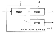
- FIG. 1B is a functional block diagram showing a configuration of a user interface device according to an embodiment of the present invention.
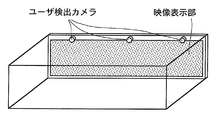
- FIG. 2A is a diagram illustrating an installation example of a user interface device according to an embodiment of the present invention.
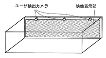
- FIG. 2B is a diagram illustrating another installation example of the user interface device according to the embodiment of the present invention.
- FIG. 2C is a diagram illustrating another installation example of the user interface device according to the embodiment of the present invention.
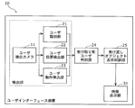
- FIG. 3 is a functional block diagram showing the configuration of the user interface device in the preferred embodiment of the present invention.
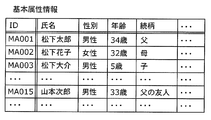
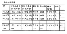
- FIG. 4A is a diagram illustrating a user information database according to an embodiment of the present invention.
- FIG. 4B is a diagram illustrating an example of basic attribute information included in the user information database.
- FIG. 4C is a diagram illustrating an example of body feature information included in the user information database.
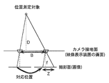
- FIG. 5A is a diagram illustrating an outline of a user position detection method according to an embodiment of the present invention.
- FIG. 5B is a diagram for explaining the principle of stereovision, which is an example of a user position detection method.
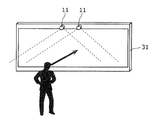
- FIG. 6A is a diagram for explaining an outline of a freehand gesture detection method according to an embodiment of the present invention.
- FIG. 6B is a diagram illustrating a procedure of a freehand gesture detection process according to the embodiment of the present invention.
- FIG. 7A is a diagram illustrating an example of a suitable use case of the user interface device according to the embodiment of the present invention.
- FIG. 7B is a diagram illustrating an example of a suitable use case of the user interface device according to the embodiment of the present invention.
- FIG. 8A is a diagram illustrating an example of a suitable use case of the user interface device according to the embodiment of the present invention.
- FIG. 8B is a diagram illustrating an example of a suitable use case of the user interface device according to the embodiment of the present invention.
- FIG. 9 is a diagram showing an operation example (upper stage), an object trajectory (middle stage), and an object moving speed (lower stage) of the user interface device according to the embodiment of the present invention.
- FIG. 10 is a flowchart showing an outline of processing of the user interface device according to the embodiment of the present invention.
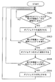
- FIG. 11 is a flowchart showing an outline of processing of the user interface device according to the embodiment of the present invention.
- a user interface device is a device that divides a video display unit into a plurality of work areas, and controls applications executed in the work areas assigned to each of the plurality of users.
- FIG. 1A is a diagram illustrating an example of an external appearance of a user interface device according to the present invention and an interface between related devices.
- the user interface device includes one or more user detection cameras and the like.
- the display on the video display unit is controlled by the position and movement of the user detected by analyzing the image information captured by the user detection camera.
- the display on the video display unit may be controlled based on the user's remote control operation such as the movement of the user's hand holding the gesture input remote control or pressing a button arranged on the remote control.
- the user interface device may accept an input of a touch table provided with an electrostatic touch pad.
- the user can use various input methods in accordance with the user's situation and the type of application.
- the user interface device acquires information from a tag (typically, an IC tag) attached to a device possessed by the user, so that the user's name, sex, age, hobby, Information such as preferences can be used for application control.
- a tag typically, an IC tag
- the user interface device may be connected to other home appliances such as a digital still camera and a digital camcorder via a wireless network or a router / hub.
- the user interface device can present the digital information / operation menu received from these devices on the screen, and can transmit user operation information for the menu presented on the screen to these devices.
- a plurality of users can collaborate such as creating / executing a slide show using a plurality of photos.
- FIG. 1B is a block diagram of the user interface device 1.
- the user interface device 1 is a device that assigns a work area to each user and enables the user to operate an object in the work area.
- the work area is displayed on the display unit 2.
- the “object” may be, for example, photo data, video data, music data, document data, and various other files (may be folder units) that can be handled by a general computer.
- object operation refers to creation, browsing, editing, deletion, etc. of the data.
- a plurality of users display a plurality of pieces of photo data in a work area assigned to each user, and browse and organize the plurality of pieces of photo data. It is also possible to exchange objects between users. For example, a first user releases an object owned by the first user from a work area assigned to the first user. Then, the second user acquires the released object and takes it into the work area assigned to the second user.
- the present invention will be described in detail by taking such a situation as an example.
- the display unit 2 is, for example, a large display panel.
- the display panel any existing display panel such as a liquid crystal display, a plasma display, and an organic EL display can be used.
- the display unit 2 displays a work area and objects.
- the display unit 2 may be a large display that displays a plurality of work areas, or may be a combination of a plurality of displays that display one work area.
- the detection unit 3 detects the position of the user located in front of the display unit 2. Furthermore, a user located in front of the display unit 2 may be identified, each user's gesture may be detected, or the amount of speech of each user may be detected.
- the detection unit 3 includes, for example, a photographing unit such as a user detection camera and an analysis unit that analyzes an image photographed by the photographing unit and detects a user position and the like. *
- the control unit 4 controls display on the display unit 2, mainly display of objects.
- an object that does not belong to any user referred to as “unaffiliated object”
- the unaffiliated object is generated, for example, when the user selects an object displayed in his / her work area and makes a gesture (referred to as “release gesture”) indicating that the object is released.
- the user interface device 1 may automatically generate an unaffiliated object.
- the control unit 4 moves the unaffiliated object in a different manner depending on whether it is located in an area on the display unit 2 facing the user (referred to as “face-to-face area”) or outside the face-to-face area.
- face-to-face area an area on the display unit 2 facing the user
- the moving speed of an unaffiliated object that moves within the facing area may be slower than when moving outside the facing area.
- the display size of the unaffiliated object that moves in the facing area may be larger than that in the case of moving outside the facing area.
- the display angle of the unaffiliated object that moves within the facing area may be made closer to the display angle at the time when the user made the release gesture.
- control unit 4 stops the unaffiliated object that has been moved within the work area assigned to the user. Thereafter, the user who has acquired the unaffiliated object can freely operate the object.
- the user can acquire the unaffiliated object by making a gesture (referred to as “acquisition gesture”) indicating that the unaffiliated object is acquired in front of the display unit 2, for example.
- acquisition gesture a gesture which turns a palm toward a screen for predetermined time may be sufficient.
- the acquisition gesture may be a gesture in which a fingertip of a thumb and a fingertip of another finger shift from an open state to a closed state.
- the acquisition gesture may be a gesture of holding a hand while rotating a palm toward the display unit from the state where the palm is directed toward the display unit.
- acquisition refusal gesture when the user makes a gesture indicating that an unaffiliated object is not acquired (referred to as “acquisition refusal gesture”), the control unit 4 is out of the facing area even when the unaffiliated object is located in the facing area of the user.
- the unaffiliated object may be moved in the movement mode at.
- acquisition refusal gesture is not particularly limited, but may be a gesture of reciprocating the hand left and right, for example. Alternatively, by not performing an acquisition gesture for a predetermined time, it may be determined that there is no intention to acquire.
- control unit 4 may control the display of the unaffiliated object based on the physical characteristics of the user. For example, the moving speed of the unaffiliated object may be decreased as the user's age is lower. Alternatively, the moving speed may be changed according to the combination of the moving direction of the object and the user's dominant arm. Alternatively, the movement speed of the unaffiliated object may be decreased as the user's height is lower. Furthermore, the display height of the unaffiliated object may be lowered as the user's height is lower.
- control unit 4 may control the display of the unaffiliated object in consideration of the attribute of the unaffiliated object and the attribute of the user. For example, if the object is content intended for children, the moving speed may be slowest in the child's facing area.
- the attribute of the unaffiliated object can be acquired from metadata attached to the object.
- a user's attribute may be acquired by communicating with the portable terminal which a user possesses, and a user's attribute information may be previously hold
- the control unit 4 may move the unaffiliated object toward the other end. .
- the unaffiliated object may be stopped, and when the predetermined time has elapsed in the stopped state, the unaffiliated object may be hidden.
- FIG. 2A to 2C are diagrams for explaining an example of installation of the user interface device of the present invention.
- the user detection camera is not only installed around the video display unit, but also installed on the wall or ceiling of the space where the video display unit is installed as shown in FIG. 2B. May be. Furthermore, you may use together what was installed in the circumference
- FIG. 2C if the floor pressure sensor is laid on the floor, the position of the user can be accurately detected from the output of the floor pressure sensor without analyzing the image of the user detection camera.
- FIG. 3 is a diagram illustrating a configuration example of the user interface device 10 according to a preferred embodiment of the present invention.
- the user interface device 10 includes a user detection camera 11, a user identification unit 21, a user position detection unit 22, a user motion detection unit 23, a reception-side user determination unit 24, a delivery object display control unit 25, and a video display. Part 31.
- the user detection camera 11, the user identification unit 21, the user position detection unit 22, and the user action detection unit 23 constitute the detection unit 3 shown in FIG. 1B.
- the delivery object display control unit 25 corresponds to the control unit 4 shown in FIG. 1B
- the video display unit 31 corresponds to the display unit 2 shown in FIG. 1B.
- the receiving-side user discriminating unit 24 is not an essential component of the present invention and can be omitted.
- 4A to 4C are diagrams for explaining the outline of the data structure of the user information DB (database).
- the user interface device 10 may include a user information DB that stores basic attribute information, body feature information, and the like.
- the basic attribute information is, for example, name, sex, age, relationship, etc. as shown in FIG. 4B.
- the basic attribute information may be referred to when the user identification unit 21 identifies a user located in front of the video display unit 31, for example.
- the body feature information stored in the user information DB is, for example, as shown in FIG. 4C, height and eye height in a standing position, height and eye height in a sitting position, dominant hand, dominant eye, It includes the body shape according to the posture of the user, such as visual acuity and hearing ability, and viewing ability.
- This body feature information may be referred to as reference information when the receiving user determining unit 24 determines a candidate recipient user, for example.
- the user detection camera 11 is an image sensor such as a CCD (Charge Coupled Device) or a CMOS (Complementary Metal Oxide Semiconductor) installed around the video display unit 31.
- the user detection camera 11 captures a user existing in front of the video display unit 31.
- the user identification unit 21 identifies a user by extracting a face area from the image of the user detection camera 11 and then collating the face image registered in advance with the extracted face image. Output user identification information.
- the user position detection unit 22 extracts a user area from a plurality of videos captured by the user detection camera 11, and then uses a stereo vision principle based on the correspondence between user areas in the plurality of videos. The relative position between the user and the video display unit 31 is calculated.
- 5A and 5B are diagrams illustrating a user position calculation method based on the principle of stereo vision in the user position detection unit 22 according to an embodiment of the present invention.
- a set of two user detection cameras 11 are installed in parallel to the screen of the video display unit 31 with an interval B.
- the user position detection unit 22 calculates the distance D between the user and the screen of the video display unit 31 based on the shift of the position of the corresponding user area in the image captured by each user detection camera 11.
- the extraction of the region in which the user is captured in the image captured by each user detection camera 11 is performed, for example, by storing the image captured by each user detection camera 11 in the absence of the user in advance and the user appears. This can be realized by obtaining a difference from the image at the time.
- the face area of the user can be obtained by detecting the face image and collating the face image, and the face area can be set as the user area.
- FIG. 5B shows the principle of stereo vision in which the distance D between the user and the installation surface of the user detection camera 11 (the screen of the video display unit 31) is obtained based on the corresponding user areas on the two images.
- the images are projected onto the two images as shown in FIG. 5B.
- the shift of the corresponding image on the image is Z
- the user position in the direction parallel to the screen of the video display unit 31 can be obtained based on the position of the user area in the image and the distance D described above.
- the user position detection unit 22 outputs the relative position of the user with respect to the video display unit 31 thus obtained.
- a distance image sensor that outputs distance information based on the principle of light wave distance measurement (Time of Flight) may be used as the user detection camera 11.
- the user position detection unit 22 can easily calculate the relative position of the user with respect to the video display unit 31 by obtaining the distance image sensor.
- the user position detection unit 22 may receive the output value of the floor pressure sensor as an input without inputting the information of the user detection camera 11.
- the relative position of the user with respect to the video display unit 31 can be calculated.
- the user motion detection unit 23 collates with which shape the hand position and the hand shape match in advance. Hand shape information such as “par”, “right selection” and “left selection” is output.
- 6A and 6B show a method for detecting the position and shape of the hand in the user motion detector 23 according to an embodiment of the present invention.
- the user motion detection unit 23 first detects a person position from an image taken by the user detection camera 11, and detects the position and shape of the hand around the person position.
- a method for estimating the position and shape of the hand for example, it can be estimated by using the following method.
- a description will be given with reference to FIG. 6B.
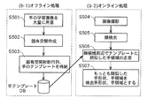
- the user motion detection unit 23 prepares a large number of learning images of the hand to be detected (S501). It is desirable that the conditions such as the illumination environment and direction in the learning image are set so that the conditions are in line with the actual detection environment.
- an eigenspace that constitutes the principal component of the hand is created from the learning image prepared in S501 using principal component analysis (S502).
- a hand template image is prepared as a sample of the hand to be detected.
- the template image may be an average image of prepared hands or images of several hands such as goo and par.
- the created projection matrix onto the eigenspace and the hand template image are stored in the hand template database (S503).
- the user detection camera 11 captures a user existing in front of the video display unit 31 (S504).
- the user operation detection unit 23 detects a face area from the image captured by the user detection camera 11 (S505).
- the user motion detection unit 23 detects a hand around the area.
- An area similar to the prepared hand template is scanned around the face area using the hand template stored in the hand template database (S506).
- the determination of the peripheral area of the face may be a range of a size set in advance based on the face position, or an area having a depth distance close to the face in the peripheral area of the face based on the principle of stereo vision using two user detection cameras 11 May be scanned to reduce the search range.
- the candidate region image of the cut out hand and the template image of the hand are projected onto the eigenspace using a projection matrix onto the eigenspace prepared in advance. Then, a method of comparing the distances between the two in the eigenspace is performed. By comparing the distances in the space representing the main component of the hand, it is possible to perform detection with reduced influence of noise such as background.
- the search area an area that satisfies a predetermined threshold and has a distance closest to the hand template is defined as a hand position. Further, the shape of the hand template having the closest distance (for example, goo, par, etc.) is set as the detected hand shape (S507).
- the detection is terminated as if the hand has not been taken.
- the template matching technique is used for detecting the position and shape of the hand, but other techniques such as a boosting technique may be used.
- the application of the user interface device 10 of the present invention associates, for example, a plurality of options with the position and shape of the hand corresponding to each option in advance. Then, it can be determined that the corresponding option has been selected according to the change in the position and shape of the user's hand detected by the user motion detection unit 23.
- the receiving-side user discriminating unit 24 includes user identification information output from the user identification unit 21, user position output from the user position detection unit 22, and hand position output from the user operation detection unit 23. Then, using the information on the shape and the input information, the user (recipient candidate user) that is estimated to be a user candidate who receives the object is determined.
- FIG. 7A to 8B are diagrams showing an example of a suitable use case of the user interface device 10 in one embodiment of the present invention.
- an object passed between users is photo data.
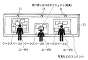
- FIG. 7A shows a case where user B passes an object.
- the receiving-side user determination unit 24 determines that the user A located on the left side of the user B is the receiving candidate user.
- the receiving-side user determination unit 24 determines that the user C located on the right side of the user B is the receiving candidate user.
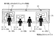
- FIG. 7B shows a case where user A passes an object.
- the receiving-side user discriminating unit 24 can determine that the user B or the user C is about to pass. Is determined as a candidate user. Which of the user B and the user C is received is determined by the gesture of the user B and the user C.
- FIG. 8A shows a case where user A passes an object.
- the workspace work area
- an application for browsing pictures is executed, and the workspace on the screen corresponding to the user C (work space C).
- the broadcast content (news program) is displayed.
- the receiving-side user determination unit 24 selects the user B, the user C, and the user D that are located on the right side of the user A. B and user D are identified as candidate users.
- the receiving-side user discriminating unit 24 does not discriminate the user C from the recipient candidate user because it has little relationship with the content (photograph) to which the application executed in the workspace corresponding to the user C is delivered.
- FIG. 8B shows a case where user A passes an object.
- an application for viewing a photograph is executed, and the user C is located in front of the video display unit 31, but executes the application. This is not the case. For example, user C is sleeping.
- the receiving-side user determination unit 24 will select the user B, the user C, and the user D located on the right side of the user A.
- the user B and the user D are received and determined as candidate users.
- the user C is located in front of the video display unit 31, but does not execute the application. Therefore, the receiving-side user determination unit 24 does not determine the user C as a candidate for receiving the user C.
- the delivery object display control unit 25 includes user identification information output from the user identification unit 21, user position output from the user position detection unit 22, hand position output from the user motion detection unit 23, and The display of the object on the screen is controlled using the shape information as input information. A specific control method will be described in “3 Operation” below.
- FIG. 9 is a diagram illustrating an operation example of the user interface device 10 according to the embodiment of the present invention.
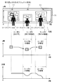
- the user interface device 10 As shown in the upper part of FIG. 9, there are three users (user A, user B, and user C) in front of the video display unit 31, and each of the three users uses a photo browsing application on the screen.
- the flow of processing of the user interface device 10 will be described by taking an example of a situation where a photograph is delivered. In other words, it is a situation in which the content is delivered so as to catch the ball on the screen.
- Three people are a family, user A is a father, user B is a daughter, user C is a mother, and user A (father) tries to give a picture to user B (daughter) and user C (mother).
- the scene will be described as an example.
- FIG. 10 is a flowchart showing an outline of processing of the user interface device 10 according to the embodiment of the present invention.
- the user identification unit 21 identifies a user by collating the faces of the users A, B, and C detected by the user detection camera 11 with body feature information stored in a user information DB registered in advance ( S801). Then, for each identified user, the user position detector 22 calculates user position information, and the user action detector 23 calculates hand position and shape information (S802).
- the receiving-side user determination unit 24 determines a candidate recipient user (S804).
- the delivery object display control unit 25 controls the movement of the delivered object according to the position of the recipient candidate user (S805).
- the delivery object display control unit 25 decelerates the object if the moving object is within the recipient candidate user's area (YES in S901) (S902).
- the recipient candidate user area may be defined based on the width of each user's workspace in the x-axis direction, or from the position on the screen in front of the user's standing position. Alternatively, a region having a predetermined size may be used.
- the delivery object display control part 25 will further decelerate an object, if a recipient candidate user performs the gesture which shows receipt selection (S903 YES) (S904). Furthermore, when the recipient candidate user performs a gesture indicating acceptance (YES in S905), the object is stopped (S906). If the object is interlocked with the movement of the hand before stopping, the receiving user can stop the object at a desired position.
- the gesture indicating reception selection may be an operation of turning the palm toward the screen for a predetermined time.
- the gesture indicating confirmation of receipt includes an operation of shifting from a state where the thumb and other fingers are opened to a closed state, or an operation of bringing the hand toward the screen toward the face or chest. Good. These operations correspond to the operation of grabbing an object, and are intuitive operations of grabbing and catching a picture on the screen.
- the user who is the recipient can easily receive the object by estimating the candidate recipient user of the object and controlling the movement of the object based on the position of the candidate recipient user.
- the gesture is assumed to be a freehand gesture, and the user's hand position and hand shape are detected from the image of the user detection camera by image analysis, but some or all of the users are shown in FIG. 1A.
- a gesture on a touch table having an electrostatic touch pad as shown may be performed, and the present invention is also effective in such a use case.
- the recipient candidate user may select to receive the object to be delivered when the hand approaches the touch table, and confirm the receipt of the object when the user touches the touch table.
- a photograph is given as an example of content delivered by a plurality of people.
- content that is suitably delivered by applying the present invention is not limited to a photo.
- Various types of content displayed on the video display unit 31 are targets of application of the present invention.
- FIGS. 5A to 9 the user is standing, but the user is not limited to standing.
- the present invention is effective even when the user is in a sitting position or the like.
- the delivery object display control unit 25 may control the movement of the delivered object in consideration of the following points.
- the movement of the object may be controlled based on the physical characteristics of the recipient candidate user.
- Examples of the user's physical characteristics include the user's age, the user's dominant arm, and the user's height. These can acquire data from the user information DB.
- the user's height can also be calculated by analyzing the image of the user detection camera.
- the size of the deceleration of the object may be larger than the predetermined value.
- usability can be improved by making the magnitude of deceleration greater than a predetermined value for elderly people and children.
- the amount of deceleration will be greater than the specified amount compared to the right-handed case. Good.
- the magnitude of deceleration may be larger than a predetermined value when the candidate user is right-handed compared to left-handed. The same effect can be obtained by setting the deceleration start position farther from the user.
- the arm length is basically positively correlated, if the height of the deceleration is greater than the predetermined value when the height is less than the predetermined value, the arm length is substantially taken into consideration. This is the control that was performed. As shown in “3 Actions” above, considering the user's height, improving the usability by controlling the trajectory of the object so that it passes through the height of the user's eyes or shoulders. Can do.
- the movement of the object may be controlled based on the attributes of the candidate recipient user.
- the trajectory and speed of the object may be controlled in view of metadata attached to the object and user attributes.
- user attributes include information recorded in tags attached to devices owned by the user, such as name, gender, age, hobbies, and preferences.
- the degree of interest in the object to be delivered is estimated based on the user's hobbies and preferences, and when the interest is estimated to be high, the degree of deceleration of the object in the vicinity of the user is determined in advance. It is better to make it larger.
- the object may be controlled by the following method.
- the object should be bounced with a rebound coefficient of 1.
- the rebound coefficient is not limited to 1.
- the number of times the object bounces at the edge of the screen may be counted, and the bounce coefficient may be changed according to the number of bounces.
- the object to be delivered reaches within a predetermined range from the edge of the screen during movement and the movement of the object is stopped, the object may be hidden.
- the recipient candidate user misses the gesture indicating the willingness of receiving once, it will bounce back, so that the gesture indicating the receiving intention can be performed at that time. Further, when the predetermined time elapses, the content is not displayed, so that it is possible to avoid the content that is not required by the recipient candidate user from being displayed on the screen forever.
- a user-specific work area is displayed in front of the user.
- the present invention is not limited to this, and a shared work area that can be shared by a plurality of users may be provided.
- a shared work area may be displayed at an intermediate point between two users, and an object acquired by the user may be stopped in the shared work area.
- the user may make an acquisition gesture while facing the direction of the shared work area (that is, facing diagonally).
- an example is shown in which an object is acquired by a user making an acquisition gesture.
- the present invention is not limited to this, and the user interface device 10 determines a user who should acquire an unaffiliated object.
- An unaffiliated object may be stopped in the work area assigned to the user.
- an unaffiliated object includes content for a child and there is only one child among a plurality of users
- the user may be made to acquire it without waiting for an acquisition gesture.
- the user may acquire the user without waiting for the user's acquisition gesture.
- the delivery object display control unit 25 may perform display control so that a plurality of objects do not overlap each other.
- the user interface device according to the present invention has been described based on the embodiment.
- the user interface device can be modified as follows, and the present invention is not limited to the user interface device described in the above embodiment. Of course.
- Each of the above devices is specifically a computer system including a microprocessor, a ROM, a RAM, a hard disk unit, a display unit, a keyboard, a mouse, and the like.
- a computer program is stored in the RAM or the hard disk unit.
- Each device achieves its function by the microprocessor operating according to the computer program.
- the computer program is configured by combining a plurality of instruction codes indicating instructions for the computer in order to achieve a predetermined function.
- Each device is not limited to a computer system including a microprocessor, a ROM, a RAM, a hard disk unit, a display unit, a keyboard, a mouse, and the like, but may be a computer system including a part of them.
- a part or all of the constituent elements constituting each of the above devices may be constituted by one system LSI (Large Scale Integration).
- the system LSI is a super multifunctional LSI manufactured by integrating a plurality of components on one chip, and specifically, a computer system including a microprocessor, a ROM, a RAM, and the like. .
- a computer program is stored in the RAM.
- the system LSI achieves its functions by the microprocessor operating according to the computer program.
- system LSI may be called IC, LSI, super LSI, or ultra LSI depending on the degree of integration.
- method of circuit integration is not limited to LSI's, and implementation using dedicated circuitry or general purpose processors is also possible.
- An FPGA Field Programmable Gate Array
- a reconfigurable processor that can reconfigure the connection and setting of circuit cells inside the LSI may be used.
- a part or all of the constituent elements constituting each of the above devices may be constituted by an IC card or a single module that can be attached to and detached from each device.
- the IC card or the module is a computer system including a microprocessor, a ROM, a RAM, and the like.
- the IC card or the module may include the super multifunctional LSI described above.
- the IC card or the module achieves its function by the microprocessor operating according to the computer program. This IC card or this module may have tamper resistance.
- the present invention may be the method described above. Further, the present invention may be a computer program that realizes these methods by a computer, or may be a digital signal composed of the computer program.
- the present invention also provides a computer-readable recording medium such as a flexible disk, hard disk, CD-ROM, MO, DVD, DVD-ROM, DVD-RAM, BD (Blu-ray Disc). ), Recorded in a semiconductor memory or the like. Further, the present invention may be the computer program or the digital signal recorded on these recording media.
- the computer program or the digital signal may be transmitted via an electric communication line, a wireless or wired communication line, a network represented by the Internet, a data broadcast, or the like.
- the present invention may also be a computer system including a microprocessor and a memory.
- the memory may store the computer program, and the microprocessor may operate according to the computer program.
- the program or the digital signal is recorded on the recording medium and transferred, or the program or the digital signal is transferred via the network or the like, and is executed by another independent computer system. It is good.
- the user interface device is useful for application to a large screen display operated by a plurality of people, for example, a large screen television or outdoor electronic advertisement (digital signage).
Landscapes
- Engineering & Computer Science (AREA)
- Multimedia (AREA)
- Signal Processing (AREA)
- Health & Medical Sciences (AREA)
- General Health & Medical Sciences (AREA)
- Theoretical Computer Science (AREA)
- Human Computer Interaction (AREA)
- General Engineering & Computer Science (AREA)
- Databases & Information Systems (AREA)
- Social Psychology (AREA)
- Computer Networks & Wireless Communication (AREA)
- Physics & Mathematics (AREA)
- General Physics & Mathematics (AREA)
- Software Systems (AREA)
- Biomedical Technology (AREA)
- Business, Economics & Management (AREA)
- Marketing (AREA)
- User Interface Of Digital Computer (AREA)
- Image Analysis (AREA)
- Details Of Television Systems (AREA)
Abstract
Description
本発明のユーザインターフェース装置は、例えば、映像表示部を複数の作業領域に分割して、複数のユーザが各々に割り当てられた作業領域で実行するアプリケーションの制御を行う装置である。
図1Aは、本発明のユーザインターフェース装置の外観と関連機器とのインターフェースの一例を説明する図である。ユーザインターフェース装置は、1以上のユーザ検出カメラなどを含む。ユーザ検出カメラにより撮影された画像情報の解析により検出されるユーザの位置及び動きにより映像表示部上の表示を制御する。
ユーザ識別部21は、ユーザ検出カメラ11の画像から顔領域の抽出を行った後、あらかじめ登録された顔画像と抽出した顔画像の照合を行うことで、ユーザを特定するユーザ識別情報を出力する。
ユーザ位置検出部22は、ユーザ検出カメラ11で撮影した複数の映像からユーザ領域の抽出を行った後、複数の映像におけるユーザ領域の対応関係からステレオ視の原理により、ユーザと映像表示部31との相対位置を算出する。
ユーザ動作検出部23は、ユーザの手領域を抽出した後、手の位置と手の形状があらかじめ規定されたどの形状に合致するか照合して、例えば「グー」「パー」「右選択」「左選択」などの手形状情報を出力する。
受け取り側ユーザ判別部24は、ユーザ識別部21が出力するユーザ識別情報、ユーザ位置検出部22が出力するユーザ位置、及びユーザ動作検出部23が出力する手の位置及び形状の情報を入力情報として、当該オブジェクトを受け取るユーザの候補と推定されるユーザ(受け手候補ユーザ)を判別する。
受け渡しオブジェクト表示制御部25は、ユーザ識別部21が出力するユーザ識別情報、ユーザ位置検出部22が出力するユーザ位置、ユーザ動作検出部23が出力する手の位置及び形状の情報を入力情報として、画面上のオブジェクトの表示の制御を行う。具体的な制御の方法については、下記の「3 動作」で説明する。
図9は、本発明の一実施形態におけるユーザインターフェース装置10の動作例を説明する図である。
ユーザAは、渡す写真を選択するために、掌を画面上に向ける。左右上下に手を動かすと、それに連動して写真のフォーカス表示が変化することで、ユーザAは所望の写真を選択することができる。上記のつかむ動作をユーザが行うことで確定することとしてもよい。
写真が選択された状態で、ユーザAが手を右側に所定以上動かすと、ユーザ動作検出部23がユーザAの動作を解釈し、写真を右側に渡す(投げる)というコマンドを生成し、当該写真が右方向に移動を開始する。これにより、当該写真が「無所属オブジェクト」となる。渡す(投げる)というコマンドに対応したジェスチャは、写真を移動したい方向に手を所定以上動かす動作とするとよい。
図9の下段に示すように、ユーザBの領域にオブジェクトが入ると、当該写真は減速するので、ユーザBはゆっくりと写真を確認することができる。また、図9の中段に示すように、ユーザの身長を考慮し、ユーザBの目の高さあるいは、肩の高さを通過するようにオブジェクトの軌道を制御すると、ユーザBにとって写真をより見やすい、より操作しやすい提示を実現することができる。ユーザの身長は、ユーザ情報DBから取得してもよいし、ユーザ検出カメラ11の画像から画像解析により概算することも可能である。
図9の中段に示すように、ユーザCの領域にオブジェクトが入ると、当該写真は再び減速するので、ユーザCはゆっくりと写真を確認することができる。ユーザCは写真を確認すると、興味のある写真であったので、受け取り選択を示すジェスチャ、すなわち、掌を画面に向ける動作を行う。そうすると、オブジェクトはさらに減速する。
(4)で掌を画面に向けた状態で所定の時間が経過すると、手の動きに当該写真の位置が連動して動く。そして、所定の時間、手の動きを所定の大きさ以内にとどめると、その位置で写真は停止する。
以下、変形例について説明する。
受け渡しオブジェクト表示制御部25は、以下の点を考慮して、受け渡しされるオブジェクトの移動を制御してもよい。
受け手候補ユーザの身体的特徴に基づいて、オブジェクトの移動を制御させてもよい。ユーザの身体的特徴の例として、ユーザの年齢、ユーザの利き腕、ユーザの身長が挙げられる。これらは、ユーザ情報DBからデータを取得することができる。また、ユーザの身長は、ユーザ検出カメラの画像を解析することからも算出できる。
受け手候補ユーザの属性に基づいて、オブジェクトの移動を制御してもよい。
受け渡しされるオブジェクトが移動して画面の端付近に到達すると、以下の方法によりオブジェクトを制御するとよい。
受け渡しされるオブジェクトが移動中に画面の端に到達した場合、当該オブジェクトを跳ね返り係数1で跳ね返ることとするとよい。勿論跳ね返り係数は1に限定されるものではない。さらに、オブジェクトが画面の端で跳ね返った回数をカウントし、前記跳ね返り回数により跳ね返り係数を変化させてもよい。
また、受け渡しされるオブジェクトが移動中に画面の端から所定の範囲内に到達した場合、当該オブジェクトの移動を停止させることとするとよい。
さらに、受け渡しされるオブジェクトが移動中に画面の端から所定の範囲内に到達し、当該オブジェクトの移動が停止された状態で所定の時間が経過すると当該オブジェクトを非表示にすることとしてもよい。
以上のように本発明にかかるユーザインターフェース装置について実施の形態に基づいて説明したが、以下のように変形することもでき、本発明は上述の実施の形態で示したユーザインターフェース装置に限られないことは勿論である。
2 表示部
3 検出部
4 制御部
11 ユーザ検出カメラ
21 ユーザ識別部
22 ユーザ位置検出部
23 ユーザ動作検出部
24 受け取り側ユーザ判別部
25 受け渡しオブジェクト表示制御部
31 映像表示部
Claims (26)
- ユーザに割り当てられた作業領域内に表示されているオブジェクトを、当該ユーザに操作させるユーザインターフェース装置であって、
前記ユーザの位置を検出する検出部と、
前記作業領域を表示する表示部と、
どのユーザにも属していない無所属オブジェクトの表示を制御する制御部とを備え、
前記制御部は、
前記検出部で検出された前記ユーザの位置に対面する前記表示部の対面領域内に前記無所属オブジェクトが位置する場合と、前記対面領域外に前記無所属オブジェクトが位置する場合とで、前記無所属オブジェクトを異なる態様で移動させ、
前記ユーザが前記無所属オブジェクトを取得した場合に、当該ユーザに割り当てられた前記作業領域内に、移動していた前記無所属オブジェクトを停止させる
ユーザインターフェース装置。 - 前記制御部は、前記対面領域内を移動する前記無所属オブジェクトの移動速度を、前記対面領域外を移動する場合より遅くする
請求項1に記載のユーザインターフェース装置。 - 前記制御部は、前記対面領域内を移動する前記無所属オブジェクトの表示サイズを、前記対面領域外を移動する場合より大きくする
請求項1に記載のユーザインターフェース装置。 - 前記検出部は、さらに、前記ユーザのジェスチャを検出し、
前記制御部は、前記無所属オブジェクトを取得することを示す取得ジェスチャが前記検出部によって検出された場合に、当該ユーザに割り当てられた前記作業領域内に前記無所属オブジェクトを停止させる
請求項1に記載のユーザインターフェース装置。 - 前記取得ジェスチャは、所定の時間、掌を画面に向けるジェスチャである
請求項4に記載のユーザインターフェース装置。 - 前記取得ジェスチャは、親指の指先と他の指の指先とが、開いた状態から閉じた状態に移行するジェスチャである
請求項4に記載のユーザインターフェース装置。 - 前記取得ジェスチャは、掌を前記表示部に向けた状態から自分自身に向かって回転させながら、手を握るジェスチャである
請求項4に記載のユーザインターフェース装置。 - 前記制御部は、前記ユーザと異なる他のユーザが所有しているオブジェクトに対して、当該オブジェクトを手放すことを示す当該他のユーザの放出ジェスチャが前記検出部によって検出された場合に、当該オブジェクトを前記無所属オブジェクトとして、表示を制御する
請求項4に記載のユーザインターフェース装置。 - 前記制御部は、前記対面領域内を移動する前記無所属オブジェクトの表示角度を、前記他のユーザが放出ジェスチャをした時点の表示角度に近づける
請求項8に記載のユーザインターフェース装置。 - 前記表示部は、複数のユーザそれぞれに割り当てられた複数の前記作業領域に区分されており、
該ユーザインターフェース装置は、さらに、前記複数のユーザのうち、前記無所属オブジェクトの受け取り候補となる受け手候補ユーザを判別する判別部を備え、
前記制御部は、
前記検出部で検出された前記受け手候補ユーザそれぞれの位置に対面する前記表示部の対面領域内に前記無所属オブジェクトが位置する場合と、前記対面領域外に前記無所属オブジェクトが位置する場合とで、前記無所属オブジェクトを異なる態様で移動させ、
前記受け手候補ユーザが前記無所属オブジェクトを取得した場合に、当該受け手候補ユーザに割り当てられた前記作業領域内に前記無所属オブジェクトを停止させる
請求項1に記載のユーザインターフェース装置。 - 前記検出部は、さらに、前記ユーザのジェスチャを検出し、
前記制御部は、前記受け手候補ユーザのいずれかに対面する前記対面領域内に前記無所属オブジェクトが位置している状態で、当該無所属オブジェクトを取得しないことを示す当該受け手候補ユーザの取得拒否ジェスチャが前記検出部で検出された場合に、前記無所属オブジェクトの移動速度を速くする
請求項10に記載のユーザインターフェース装置。 - 前記取得拒否ジェスチャは、手を左右に往復させるジェスチャである
請求項11に記載のユーザインターフェース装置。 - 前記取得拒否ジェスチャは、前記取得ジェスチャをせずにいる状態である
請求項11に記載のユーザインターフェース装置。 - 前記制御部は、さらに、前記ユーザの身体的特徴に基づいて、前記無所属オブジェクトの表示を制御する
請求項1に記載のユーザインターフェース装置。 - 前記身体的特徴は、前記ユーザの年齢であり、
前記制御部は、前記ユーザの年齢が低い程、前記対面領域内を移動する前記無所属オブジェクトの移動速度を遅くする
請求項14に記載のユーザインターフェース装置。 - 前記身体的特徴は、前記ユーザの利き腕であり、
前記制御部は、オブジェクトの前記表示面上での移動方向と利き腕との組合せに応じて、前記対面領域内を移動する前記無所属オブジェクトの移動速度を変更する
請求項14に記載のユーザインターフェース装置。 - 前記身体的特徴は、前記ユーザの身長であり、
前記制御部は、前記ユーザの身長が低い程、前記対面領域内を移動する前記無所属オブジェクトの移動速度を遅くする
請求項14に記載のユーザインターフェース装置。 - 前記身体的特徴は、前記ユーザの身長であり、
前記制御部は、前記ユーザの身長が低い程、前記対面領域内を移動する前記無所属オブジェクトの表示高さを低くする
請求項14に記載のユーザインターフェース装置。 - 前記制御部は、前記無所属オブジェクトに付与されたメタデータと、前記ユーザの属性情報とに応じて、前記無所属オブジェクトの表示を制御する
請求項1に記載のユーザインターフェース装置。 - 前記制御部は、前記ユーザの所持する携帯端末と通信することによって、前記属性情報を取得する
請求項19に記載のユーザインターフェース装置。 - 前記オブジェクトは、写真である
請求項1に記載のユーザインターフェース装置。 - 前記制御部は、前記無所属オブジェクトが前記表示部の一方の端に到達した場合、当該無所属オブジェクトを他方の端に向かって移動させる
請求項1に記載のユーザインターフェース装置。 - 前記制御部は、前記無所属オブジェクトが前記表示部の端から所定の距離離れた位置に到達した場合に、当該無所属オブジェクトを停止させる
請求項1に記載のユーザインターフェース装置。 - 前記制御部は、前記無所属オブジェクトを停止した状態で所定の時間が経過した場合に、当該無所属オブジェクトを非表示にする
請求項23に記載のユーザインターフェース装置。 - 作業領域を表示する表示部を用いて、ユーザに割り当てられた前記作業領域内に表示されるオブジェクトを、当該ユーザに操作させるユーザインターフェース方法であって、
前記ユーザの位置を検出する検出ステップと、
どのユーザにも属していない無所属オブジェクトの表示を制御する制御ステップとを含み、
前記制御ステップでは、
前記検出ステップで検出された前記ユーザの位置に対面する前記表示部の対面領域内に前記無所属オブジェクトが位置する場合と、前記対面領域外に前記無所属オブジェクトが位置する場合とで、前記無所属オブジェクトを異なる態様で移動させ、
前記ユーザが前記無所属オブジェクトを取得した場合に、当該ユーザに割り当てられた前記作業領域内に、移動していた前記無所属オブジェクトを停止させる
ユーザインターフェース方法。 - 請求項25に記載のユーザインターフェース方法を、コンピュータに実行させるプログラムを記録した
コンピュータ読み取り可能な記録媒体。
Priority Applications (4)
| Application Number | Priority Date | Filing Date | Title |
|---|---|---|---|
| EP09815911.4A EP2330558B1 (en) | 2008-09-29 | 2009-09-28 | User interface device, user interface method, and recording medium |
| JP2010503294A JP5345129B2 (ja) | 2008-09-29 | 2009-09-28 | ユーザインターフェース装置、ユーザインターフェース方法、及び記録媒体 |
| US12/744,373 US8451216B2 (en) | 2008-09-29 | 2009-09-28 | User interface device, user interface method, and recording medium |
| CN2009801011706A CN101878487B (zh) | 2008-09-29 | 2009-09-28 | 用户接口装置、用户接口方法、以及记录媒体 |
Applications Claiming Priority (2)
| Application Number | Priority Date | Filing Date | Title |
|---|---|---|---|
| JP2008-251044 | 2008-09-29 | ||
| JP2008251044 | 2008-09-29 |
Publications (1)
| Publication Number | Publication Date |
|---|---|
| WO2010035491A1 true WO2010035491A1 (ja) | 2010-04-01 |
Family
ID=42059503
Family Applications (1)
| Application Number | Title | Priority Date | Filing Date |
|---|---|---|---|
| PCT/JP2009/004911 Ceased WO2010035491A1 (ja) | 2008-09-29 | 2009-09-28 | ユーザインターフェース装置、ユーザインターフェース方法、及び記録媒体 |
Country Status (5)
| Country | Link |
|---|---|
| US (1) | US8451216B2 (ja) |
| EP (1) | EP2330558B1 (ja) |
| JP (1) | JP5345129B2 (ja) |
| CN (1) | CN101878487B (ja) |
| WO (1) | WO2010035491A1 (ja) |
Cited By (7)
| Publication number | Priority date | Publication date | Assignee | Title |
|---|---|---|---|---|
| JP2011227828A (ja) * | 2010-04-22 | 2011-11-10 | Canon Inc | 情報処理装置、その処理方法及びプログラム |
| EP2741203A2 (en) | 2012-12-06 | 2014-06-11 | Konica Minolta, Inc. | Object operation apparatus and non-transitory computer-readable storage medium |
| JP2016512632A (ja) * | 2013-03-15 | 2016-04-28 | インテル コーポレイション | 音声およびジェスチャー・コマンド領域を割り当てるためのシステムおよび方法 |
| JP2016177428A (ja) * | 2015-03-19 | 2016-10-06 | 富士通株式会社 | 表示方法、プログラム及び表示制御装置 |
| WO2016157654A1 (ja) * | 2015-03-31 | 2016-10-06 | ソニー株式会社 | 情報処理装置、情報処理方法およびプログラム |
| JP2018005473A (ja) * | 2016-06-30 | 2018-01-11 | シャープ株式会社 | 画像表示装置及びプログラム |
| JP2020161058A (ja) * | 2019-03-28 | 2020-10-01 | シャープ株式会社 | 情報処理装置 |
Families Citing this family (20)
| Publication number | Priority date | Publication date | Assignee | Title |
|---|---|---|---|---|
| JP5345113B2 (ja) * | 2010-09-08 | 2013-11-20 | シャープ株式会社 | コンテンツ出力システム、出力制御装置、出力制御方法、及びコンピュータプログラム |
| JP5807399B2 (ja) * | 2011-06-13 | 2015-11-10 | ソニー株式会社 | 情報処理装置及びプログラム |
| US20130009875A1 (en) * | 2011-07-06 | 2013-01-10 | Fry Walter G | Three-dimensional computer interface |
| US8687023B2 (en) * | 2011-08-02 | 2014-04-01 | Microsoft Corporation | Cross-slide gesture to select and rearrange |
| JP5902444B2 (ja) * | 2011-11-24 | 2016-04-13 | 京セラ株式会社 | 携帯端末装置、プログラムおよび表示制御方法 |
| WO2013099407A1 (ja) * | 2011-12-28 | 2013-07-04 | 株式会社ニコン | 表示装置及び投影装置 |
| US9690368B2 (en) | 2011-12-30 | 2017-06-27 | Adidas Ag | Customization based on physiological data |
| US10402879B2 (en) | 2011-12-30 | 2019-09-03 | Adidas Ag | Offering a customized collection of products |
| US8902198B1 (en) | 2012-01-27 | 2014-12-02 | Amazon Technologies, Inc. | Feature tracking for device input |
| JP5651639B2 (ja) * | 2012-06-29 | 2015-01-14 | 株式会社東芝 | 情報処理装置、情報表示装置、情報処理方法およびプログラム |
| CN103838483B (zh) | 2012-11-27 | 2018-02-27 | 联想(北京)有限公司 | 一种显示方法及电子设备 |
| US9060162B2 (en) * | 2012-12-21 | 2015-06-16 | Ati Technologies Ulc | Providing multiple viewer preferences on a display device |
| US9460453B2 (en) | 2013-03-13 | 2016-10-04 | Intel Corporation | System and method to provide location-based digital signage services |
| US9268929B2 (en) * | 2013-03-15 | 2016-02-23 | Intelmate Llc | Dossier packaging |
| KR102241074B1 (ko) * | 2014-07-22 | 2021-04-16 | 엘지전자 주식회사 | 디스플레이 디바이스 및 그 제어 방법 |
| KR102194923B1 (ko) | 2014-07-22 | 2020-12-24 | 엘지전자 주식회사 | 디스플레이 디바이스 및 그 제어 방법 |
| JP2016053769A (ja) * | 2014-09-02 | 2016-04-14 | ソニー株式会社 | 情報処理装置、情報処理方法およびプログラム |
| JP2017126935A (ja) * | 2016-01-15 | 2017-07-20 | ソニー株式会社 | 情報処理装置、情報処理システム、および情報処理方法、並びにプログラム |
| CN105892665B (zh) * | 2016-03-31 | 2019-02-05 | 联想(北京)有限公司 | 信息处理方法及电子设备 |
| WO2019130896A1 (ja) * | 2017-12-27 | 2019-07-04 | ソニー株式会社 | 表示制御装置、表示制御方法およびプログラム |
Citations (6)
| Publication number | Priority date | Publication date | Assignee | Title |
|---|---|---|---|---|
| JP2000222133A (ja) * | 1999-01-28 | 2000-08-11 | Canon Inc | 電子情報表示装置及びその表示制御方法並びに記憶媒体 |
| JP2002157079A (ja) | 2000-11-09 | 2002-05-31 | Doko Kagi Kofun Yugenkoshi | 意向識別方法 |
| JP2003263145A (ja) | 2002-03-07 | 2003-09-19 | Pioneer Electronic Corp | 情報表示装置 |
| JP2005227487A (ja) * | 2004-02-12 | 2005-08-25 | Hitachi Ltd | テーブル型情報端末の表示・操作方法 |
| JP2005346353A (ja) * | 2004-06-02 | 2005-12-15 | Fuji Photo Film Co Ltd | 画像表示制御テーブル、画像の天地制御方法及び画像の天地制御プログラム |
| JP2006011914A (ja) * | 2004-06-28 | 2006-01-12 | Fuji Photo Film Co Ltd | 画像表示制御装置及び画像表示制御プログラム |
Family Cites Families (12)
| Publication number | Priority date | Publication date | Assignee | Title |
|---|---|---|---|---|
| CA2068486C (en) | 1991-08-30 | 1998-09-15 | Stephen S. Fleming | System and graphical method for creating an object |
| JP3968477B2 (ja) * | 1997-07-07 | 2007-08-29 | ソニー株式会社 | 情報入力装置及び情報入力方法 |
| US7397464B1 (en) * | 2004-04-30 | 2008-07-08 | Microsoft Corporation | Associating application states with a physical object |
| US7519223B2 (en) * | 2004-06-28 | 2009-04-14 | Microsoft Corporation | Recognizing gestures and using gestures for interacting with software applications |
| JP4742531B2 (ja) * | 2004-07-21 | 2011-08-10 | 株式会社日立製作所 | 情報表示装置 |
| US20070064004A1 (en) * | 2005-09-21 | 2007-03-22 | Hewlett-Packard Development Company, L.P. | Moving a graphic element |
| JP4725423B2 (ja) * | 2006-06-06 | 2011-07-13 | パナソニック株式会社 | 画像処理装置 |
| EP1895391A1 (en) | 2006-08-16 | 2008-03-05 | Siemens Aktiengesellschaft | Method and system for displaying a multitude of objects on a display |
| JP5132131B2 (ja) * | 2006-11-17 | 2013-01-30 | 任天堂株式会社 | ポインティング装置の調整プログラムおよびポインティング装置 |
| JP2008181248A (ja) * | 2007-01-23 | 2008-08-07 | Kyocera Mita Corp | 表示制御装置及び表示制御プログラム |
| US20090106667A1 (en) * | 2007-10-19 | 2009-04-23 | International Business Machines Corporation | Dividing a surface of a surface-based computing device into private, user-specific areas |
| WO2009154045A1 (ja) * | 2008-06-20 | 2009-12-23 | コニカミノルタホールディングス株式会社 | 情報処理方法および情報処理装置 |
-
2009
- 2009-09-28 WO PCT/JP2009/004911 patent/WO2010035491A1/ja not_active Ceased
- 2009-09-28 EP EP09815911.4A patent/EP2330558B1/en active Active
- 2009-09-28 JP JP2010503294A patent/JP5345129B2/ja active Active
- 2009-09-28 US US12/744,373 patent/US8451216B2/en active Active
- 2009-09-28 CN CN2009801011706A patent/CN101878487B/zh active Active
Patent Citations (6)
| Publication number | Priority date | Publication date | Assignee | Title |
|---|---|---|---|---|
| JP2000222133A (ja) * | 1999-01-28 | 2000-08-11 | Canon Inc | 電子情報表示装置及びその表示制御方法並びに記憶媒体 |
| JP2002157079A (ja) | 2000-11-09 | 2002-05-31 | Doko Kagi Kofun Yugenkoshi | 意向識別方法 |
| JP2003263145A (ja) | 2002-03-07 | 2003-09-19 | Pioneer Electronic Corp | 情報表示装置 |
| JP2005227487A (ja) * | 2004-02-12 | 2005-08-25 | Hitachi Ltd | テーブル型情報端末の表示・操作方法 |
| JP2005346353A (ja) * | 2004-06-02 | 2005-12-15 | Fuji Photo Film Co Ltd | 画像表示制御テーブル、画像の天地制御方法及び画像の天地制御プログラム |
| JP2006011914A (ja) * | 2004-06-28 | 2006-01-12 | Fuji Photo Film Co Ltd | 画像表示制御装置及び画像表示制御プログラム |
Non-Patent Citations (1)
| Title |
|---|
| See also references of EP2330558A4 |
Cited By (8)
| Publication number | Priority date | Publication date | Assignee | Title |
|---|---|---|---|---|
| JP2011227828A (ja) * | 2010-04-22 | 2011-11-10 | Canon Inc | 情報処理装置、その処理方法及びプログラム |
| EP2741203A2 (en) | 2012-12-06 | 2014-06-11 | Konica Minolta, Inc. | Object operation apparatus and non-transitory computer-readable storage medium |
| JP2016512632A (ja) * | 2013-03-15 | 2016-04-28 | インテル コーポレイション | 音声およびジェスチャー・コマンド領域を割り当てるためのシステムおよび方法 |
| JP2016177428A (ja) * | 2015-03-19 | 2016-10-06 | 富士通株式会社 | 表示方法、プログラム及び表示制御装置 |
| WO2016157654A1 (ja) * | 2015-03-31 | 2016-10-06 | ソニー株式会社 | 情報処理装置、情報処理方法およびプログラム |
| JP2018005473A (ja) * | 2016-06-30 | 2018-01-11 | シャープ株式会社 | 画像表示装置及びプログラム |
| JP2020161058A (ja) * | 2019-03-28 | 2020-10-01 | シャープ株式会社 | 情報処理装置 |
| JP7256665B2 (ja) | 2019-03-28 | 2023-04-12 | シャープ株式会社 | 情報処理装置 |
Also Published As
| Publication number | Publication date |
|---|---|
| US20100259473A1 (en) | 2010-10-14 |
| EP2330558A1 (en) | 2011-06-08 |
| EP2330558B1 (en) | 2016-11-02 |
| EP2330558A4 (en) | 2014-04-30 |
| US8451216B2 (en) | 2013-05-28 |
| JPWO2010035491A1 (ja) | 2012-02-16 |
| CN101878487A (zh) | 2010-11-03 |
| CN101878487B (zh) | 2013-04-10 |
| JP5345129B2 (ja) | 2013-11-20 |
Similar Documents
| Publication | Publication Date | Title |
|---|---|---|
| JP5345129B2 (ja) | ユーザインターフェース装置、ユーザインターフェース方法、及び記録媒体 | |
| JP5260643B2 (ja) | ユーザインターフェース装置、ユーザインターフェース方法、及び記録媒体 | |
| US11513608B2 (en) | Apparatus, method and recording medium for controlling user interface using input image | |
| US9939914B2 (en) | System and method for combining three-dimensional tracking with a three-dimensional display for a user interface | |
| CN105320428B (zh) | 用于提供图像的方法和设备 | |
| US8379098B2 (en) | Real time video process control using gestures | |
| US8666115B2 (en) | Computer vision gesture based control of a device | |
| KR20250103813A (ko) | 생산성을 위한 확장 현실 | |
| CN105009025B (zh) | 基于观看距离的自适应屏幕接口 | |
| US9971491B2 (en) | Gesture library for natural user input | |
| US20150293597A1 (en) | Method, Apparatus and Computer Program for Enabling a User Input Command to be Performed | |
| CN103797513A (zh) | 对内容的基于计算机视觉的双手控制 | |
| CN102906671A (zh) | 手势输入装置及手势输入方法 | |
| JP2012238293A (ja) | 入力装置 | |
| Chu et al. | Hand gesture for taking self portrait | |
| CN121764325A (zh) | 基于手势的内容选择和传输 |
Legal Events
| Date | Code | Title | Description |
|---|---|---|---|
| WWE | Wipo information: entry into national phase |
Ref document number: 200980101170.6 Country of ref document: CN |
|
| WWE | Wipo information: entry into national phase |
Ref document number: 2010503294 Country of ref document: JP |
|
| 121 | Ep: the epo has been informed by wipo that ep was designated in this application |
Ref document number: 09815911 Country of ref document: EP Kind code of ref document: A1 |
|
| WWE | Wipo information: entry into national phase |
Ref document number: 12744373 Country of ref document: US |
|
| REEP | Request for entry into the european phase |
Ref document number: 2009815911 Country of ref document: EP |
|
| WWE | Wipo information: entry into national phase |
Ref document number: 2009815911 Country of ref document: EP |
|
| NENP | Non-entry into the national phase |
Ref country code: DE |