WO2010035541A1 - Dispositif de commande d’alimentation en eau - Google Patents
Dispositif de commande d’alimentation en eau Download PDFInfo
- Publication number
- WO2010035541A1 WO2010035541A1 PCT/JP2009/058192 JP2009058192W WO2010035541A1 WO 2010035541 A1 WO2010035541 A1 WO 2010035541A1 JP 2009058192 W JP2009058192 W JP 2009058192W WO 2010035541 A1 WO2010035541 A1 WO 2010035541A1
- Authority
- WO
- WIPO (PCT)
- Prior art keywords
- water
- water level
- electrode rod
- water supply
- detection electrode
- Prior art date
- Legal status (The legal status is an assumption and is not a legal conclusion. Google has not performed a legal analysis and makes no representation as to the accuracy of the status listed.)
- Ceased
Links
Images


Classifications
-
- F—MECHANICAL ENGINEERING; LIGHTING; HEATING; WEAPONS; BLASTING
- F22—STEAM GENERATION
- F22B—METHODS OF STEAM GENERATION; STEAM BOILERS
- F22B37/00—Component parts or details of steam boilers
- F22B37/78—Adaptations or mounting of level indicators
-
- F—MECHANICAL ENGINEERING; LIGHTING; HEATING; WEAPONS; BLASTING
- F22—STEAM GENERATION
- F22B—METHODS OF STEAM GENERATION; STEAM BOILERS
- F22B21/00—Water-tube boilers of vertical or steeply-inclined type, i.e. the water-tube sets being arranged vertically or substantially vertically
- F22B21/34—Water-tube boilers of vertical or steeply-inclined type, i.e. the water-tube sets being arranged vertically or substantially vertically built-up from water tubes grouped in panel form surrounding the combustion chamber, i.e. radiation boilers
- F22B21/348—Radiation boilers with a burner at the top
-
- F—MECHANICAL ENGINEERING; LIGHTING; HEATING; WEAPONS; BLASTING
- F22—STEAM GENERATION
- F22D—PREHEATING, OR ACCUMULATING PREHEATED, FEED-WATER FOR STEAM GENERATION; FEED-WATER SUPPLY FOR STEAM GENERATION; CONTROLLING WATER LEVEL FOR STEAM GENERATION; AUXILIARY DEVICES FOR PROMOTING WATER CIRCULATION WITHIN STEAM BOILERS
- F22D5/00—Controlling water feed or water level; Automatic water feeding or water-level regulators
- F22D5/26—Automatic feed-control systems
Definitions
- the present invention relates to a water supply control device.
- This application claims priority based on Japanese Patent Application No. 2008-245631 for which it applied to Japan on September 25, 2008, and uses the content here.
- the water level in the water pipe (hereinafter referred to as “canned water”) is used to prevent overheating of the water pipe, which is a heat transfer section, and to make the generated steam have a predetermined dryness.
- Water supply control is performed to maintain (hereinafter referred to as “in-pipe water level”) within a predetermined range.
- a water level detection electrode rod is usually used, and the water level detection electrode rod detects the in-pipe water level by directly or indirectly contacting with the can water of the boiler device.
- the boiler device is configured such that a specific pipe water level is detected by the water level detection electrode rod, and the pipe water level is maintained within a predetermined range based on the detected pipe water level.
- the water level detection electrode rod when the water level detection electrode rod is attached to the water pipe and the water level in the pipe is directly detected, the water level detection electrode bar may come into contact with the air bubbles to detect a water level higher than the actual water level in the pipe. Thereby, even if the boiler device does not satisfy the target water level, the target water level is detected by the water level detection electrode rod, and there is a possibility that the water pipe is damaged due to insufficient water level.
- the boiler device may be repeatedly activated and stopped in a short time depending on the type of steam-use equipment to be connected and the operation status.
- the water level detection electrode rod detects the actual water level.
- the water level detection electrode rod detects the actual water level.
- the water level becomes higher than the target water level.
- a boiler apparatus was started with a high water level, since can water boiled in the state where the in-pipe water level was high, there existed a problem that can water was accompanied and flowed out with steam and the dryness of steam fell.
- This invention is made in view of the said problem, Comprising: It aims at providing the water supply control apparatus which can prevent the fall of the dryness of the vapor
- the water supply control device of the present invention is mounted on a water pipe accommodated in a boiler can body, a water level detection electrode rod capable of detecting a specific water level inside the water pipe, a water supply pump for supplying water to the boiler can body, and the water supply pump
- a control unit that controls start and stop of the water supply, and the control unit starts the water supply pump when the water level detection electrode rod detects the specific water level, and controls the pressure of the water pipe and the water pipe.
- a start time of the water supply pump is determined based on a supplied water temperature, and the water supply pump is stopped after the start time has elapsed.
- the water supply control device of the present invention is mounted on a water pipe accommodated in a boiler can body, a water level detection electrode rod capable of detecting a specific water level inside the water pipe, a water supply pump for supplying water to the boiler can body, A control unit that controls start and stop of the water supply pump, and the control unit starts the water supply pump when the water level detection electrode rod does not detect the specific water level, and the start of the water supply pump
- the start time of the water supply pump after detection is determined based on the pressure of the water pipe and the temperature of the water supplied to the water pipe, and after the start time has elapsed. The water supply pump is stopped.
- a water supply control device capable of preventing a decrease in dryness of generated steam and damage of a water pipe.
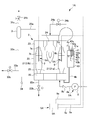
- FIG. 1 is a schematic diagram illustrating a schematic configuration of a boiler apparatus having a water supply control device according to a first embodiment of the present invention.
- the boiler device 1 is mainly composed of a boiler body 2, a steam / water separator 3, a water level detection device 4, and a water supply control device 5.
- the boiler device 1 can perform so-called double water level control by using a water level detection device 4 and a water supply control device 5 described in detail later.
- the boiler apparatus 1 is mounted
- Water supply control is performed using the second water level detection electrode rod 7.
- the 1st water level detection electrode rod 6 and the 2nd water level detection electrode rod 7 are mounted
- the boiler body 2 includes a boiler can body 20, a plurality of water pipes 21, a lower header 22, an upper header 23, and a heating burner 24.
- the boiler can body 20 is formed in a substantially cylindrical shape and constitutes the appearance of the boiler body 2.
- the plurality of water tubes 21 are accommodated inside the boiler can body 20 and are erected at predetermined intervals in the circumferential direction of the boiler can body 20.
- the plurality of water tubes 21 define a combustion chamber 25 provided at a substantially central portion of the boiler can body 20. That is, the plurality of water pipes 21 are erected at predetermined intervals in the circumferential direction of the boiler can body 20 so as to surround the combustion chamber 25 inside the boiler can body 20.
- the heating burner 24 is provided above the combustion chamber 25.
- the heating burner 24 heats the plurality of water tubes 21 to boil and vaporize the can water introduced into the plurality of water tubes 21 to generate an air-water mixture (steam).
- the heating burner 24 is connected to a fuel tank (not shown) through a fuel line 24a.
- a flow rate adjusting valve 24b is provided in the fuel line 24a.
- the combustion amount of the heating burner 24 is configured to be adjusted continuously or stepwise by adjusting the opening degree of the flow rate adjusting valve 24b.
- the heating burner 24 is configured to be adjustable such that the opening degree of the flow rate adjusting valve 24b is 100% high combustion, the low opening degree is 50%, and the opening degree is 0% stop.
- the lower header 22 is provided at the lower part of the boiler can body 20 and is connected to the lower ends of the plurality of water pipes 21.
- One side of the water supply line 8a is connected to the lower header 22, and the water supply pump 8 connected to a water supply tank (not shown) is connected to the other side of the water supply line 8a.
- Water stored in the water supply tank is introduced into the lower header 22 by the water supply pump 8 through the water supply line 8a.
- the water introduced into the lower header 22 is further introduced into a plurality of water pipes 21 connected to the lower header 22.
- the boiler apparatus 1 which concerns on this embodiment comprises what is called a once-through boiler.
- a blow line 22 a is connected to the lower header 22.
- the blow line 22a is provided with a blow valve 22b.
- the lower header 22 is configured to be able to discharge all or a predetermined amount of water introduced by the water supply pump 8 and / or can water introduced into the lower header 22 by opening the blow valve 22b.
- the upper header 23 is provided at the upper part of the boiler can body 20 and is connected to the upper ends of the plurality of water pipes 21.
- the upper header 23 is connected to one side of a steam / water line 23a, and the steam / water separator 3 is connected to the other side of the steam / water line 23a.
- the upper header 23 collects the air / water mixture (steam) generated by the plurality of water pipes 21 by the heating burner 24 and sends it to the steam / water separator 3 through the air / water line 23a.
- the steam / water separator 3 is connected to the upper header 23 via the steam / water line 23a.
- the steam separator 3 separates dry steam and moisture from the steam / water mixture (steam) generated by the heating burner 24 and sent out from the upper header 23.
- the steam separator 3 is connected to a steam communication line 31a connected to a predetermined steam use device (not shown).
- the dry steam separated by the steam separator 3 is sent to a predetermined steam using device via the steam communication line 31a. Note that the amount of dry steam delivered to a predetermined steam-using device is adjusted by opening / closing an opening / closing valve 31b provided in the steam communication line 31a.
- the water separated by the steam separator 3 is sent out to the lower header 22 via a precipitation line 32 a connecting the steam separator 3 and the lower header 22.
- the concentration blow line 33a is connected to the precipitation line 32a.
- the concentration blow line 33a is provided with a concentration blow valve 33b.
- the boiler device 1 is configured to drain predetermined water (high-concentration can water, etc.) separated by the steam / water separator 3 and / or water at the start-up of the boiler device 1 by opening the concentration blow valve 33b.
- an electrical conductivity measurement sensor 34 is provided downstream of the concentration blow line 33a in the precipitation line 32a. The electrical conductivity measurement sensor 34 measures the electrical conductivity of water supplied when the boiler device 1 is started up, the concentration of can water concentrated by long-time operation of the boiler device 1, and the like.
- the water level detection device 4 includes a water level control cylinder 40 formed of a conductive metal, a high water level electrode rod 41, a middle water level electrode rod 42, a low water level electrode rod 43, and a control unit (not shown). It is prepared for. The water level detection device 4 is controlled based on the in-pipe water levels of the plurality of water pipes 21 indirectly detected by the high water level electrode rod 41, the middle water level electrode rod 42 and the low water level electrode rod 43 inside the water level control cylinder 40. The water supply pump 8 is started and stopped by the unit.
- the water level control cylinder 40 is formed in a substantially cylindrical shape with both ends sealed.
- a communication pipe 4 a is connected to the upper end portion of the water level control cylinder 40, and the communication pipe 4 a is connected to the upper header 23.
- a communication pipe 4 b is connected to the lower end of the water level control cylinder 40, and the communication pipe 4 b is connected to the lower header 22.
- the water level control cylinder 40 has an upper end and a lower end communicating with the plurality of water pipes 21 via the upper header 23 and the lower header 22, thereby controlling the water level in the pipe similar to the can water introduced into the plurality of water pipes 21. It is realized inside the tube 40.
- the high water level electrode rod 41 detects the high water level inside the water level control cylinder 40.
- the high water level is a target water level when water is supplied during normal operation of the boiler body 2. That is, when the high water level electrode rod 41 and the can water come into contact with each other, the water level detection device 4 detects the high water level and stops water supply by the water supply pump 8.
- the high water level electrode rod 41 includes an external connection terminal 41a provided on one end side and an electrode portion 41b provided on the other end side.
- the high water level electrode rod 41 is disposed so that the external connection terminal 41a protrudes outside the water level control cylinder 40 and the electrode portion 41b is accommodated inside the water level control cylinder 40, and is a cylindrical insulator (not shown). To the upper end of the water level control cylinder 40.
- the external connection terminal 41a is connected to one side of a predetermined power source (not shown), and the electrode portion 41b is formed in a rod shape from stainless steel.
- the other side of the predetermined power supply unit is connected to the water level control cylinder 40. Therefore, for example, when the water inside the water level control cylinder 40 reaches a high water level and the electrode part 41b comes into contact with the can water, the energization state between the external connection terminal 41a and the water level control cylinder 40 changes. Thereby, a high water level is detected.
- the middle water level electrode rod 42 detects the middle water level inside the water level control cylinder 40.
- the medium water level means that the water supply to the boiler can body 20 is started on condition that the medium water level electrode rod 42 and the can water do not come into contact with each other (the can water inside the water level control cylinder 40 does not satisfy the medium water level).
- the water level is controlled.
- the middle water level electrode rod 42 includes an external connection terminal 42a provided on one end side and an electrode portion 42b provided on the other end side.
- the middle water level electrode rod 42 is disposed so that the external connection terminal 42a protrudes outside the water level control cylinder 40 and the electrode portion 42b is accommodated inside the water level control cylinder 40, and is a cylindrical insulator (not shown). To the upper end of the water level control cylinder 40.
- the intermediate water level electrode rod 42 has an external connection terminal 42a connected to one side of a predetermined power source (not shown), and the electrode 42b is formed of a stainless steel rod.
- the other side of the predetermined power supply unit is connected to the water level control cylinder 40. Therefore, for example, when the water inside the water level control cylinder 40 decreases from the middle water level and the electrode part 42b does not contact the can water, the energization state between the external connection terminal 42a and the water level control cylinder 40 changes. . Thereby, the middle water level is detected.
- the low water level electrode rod 43 detects the low water level inside the water level control cylinder 40.
- the low water level means that the boiler body 2 is interlocked on the condition that the low water level electrode rod 43 and the can water do not come into contact with each other (the water inside the water level control cylinder 40 does not satisfy the low water level). This is the water level at which control for stopping the operation of the boiler body 2 is performed.
- the low water level electrode rod 43 includes an external connection terminal 43a provided on one end side and an electrode portion 43b provided on the other end side.
- the low water level electrode rod 43 is arranged so that the external connection terminal 43a protrudes outside the water level control cylinder 40 and the electrode portion 43b is accommodated inside the water level control cylinder 40, and is a cylindrical insulator (not shown). To the upper end of the water level control cylinder 40.
- the low water level electrode rod 43 has an external connection terminal 43a connected to one side of a predetermined power source (not shown), and the electrode 43b is formed of a stainless steel rod.
- the other side of the predetermined power supply unit is connected to the water level control cylinder 40. Therefore, for example, when the water inside the water level control cylinder 40 decreases from the low water level and the electrode portion 43b does not come into contact with the can water, the energization state between the external connection terminal 43a and the water level control cylinder 40 changes. . Thereby, a low water level is detected.
- the control unit is connected to the high water level electrode rod 41, the middle water level electrode rod 42, the low water level electrode rod 43, and the water supply pump 8 through a predetermined line (not shown). Based on the in-pipe water levels of the plurality of water pipes 21 indirectly detected by the high water level electrode rod 41, the middle water level electrode rod 42, and the low water level electrode rod 43 inside the water level control cylinder 40, the control unit 8 Controls start and stop of. Specifically, the control unit activates the water supply pump 8 and starts supplying water to the boiler can body 20 on the condition that the middle water level electrode rod 42 and the can water do not contact with each other inside the water level control cylinder 40.
- the water supply control device 5 includes a first water level detection electrode rod 6, a second water level detection electrode rod 7, a water supply pump 8, and a control unit 9.
- the water supply control device 5 supplies water from the steam pressure and the water supply pump 8 when the first water level detection electrode rod 6 or the second water level detection electrode rod 7 detects the first water level which is a specific water level.
- the start time of the feed water pump 8 is determined based on the feed water temperature of the water to be supplied, the feed water pump 8 is started, and the feed water pump 8 is stopped after a predetermined start time has elapsed, so that the target water level is satisfied. Take control.
- the first water level detection electrode rod 6 is attached from the upper header 23 to the upper end portion of the first water pipe 21a.
- the first water pipe 21a is a water pipe arranged in the vicinity of the heating burner 24.
- the first water level detection electrode rod 6 includes a first external terminal 6a provided on one end side and a first electrode portion 6b provided on the other end side.
- the first water level detection electrode rod 6 is arranged such that the first external terminal 6a protrudes outside the first water pipe 21a and the first electrode portion 6b is accommodated inside the first water pipe 21a.
- the first water level detection electrode rod 6 is held at the upper end of the first water pipe 21a by a cylindrical insulator (not shown).
- the first electrode portion 6b is made of stainless steel formed in a rod shape, and its surface is covered with an insulating film made of engineer plastic.
- an insulating film made of engineer plastic.
- engineer plastic with high heat resistance, high pressure resistance and high chemical resistance is preferable, and ketone-based synthetic resin materials such as polyether ether ketone, polyether ketone, polyether ketone ketone, polyallyl ether ketone, Or polyether ether ketone with high heat resistance can be illustrated.
- the first electrode portion 6b is formed in a predetermined length so that a specific water level introduced into the first water pipe 21a can be detected. That is, the 1st electrode part 6b should just have a length which can contact the can water introduced so that the specific water level may be satisfy
- the first water level detection electrode rod 6 configured as described above has a first external terminal 6a connected to one side of a predetermined power source (not shown), and the other side of the power source is a metal first water tube.
- the first electrode portion 6b becomes a capacitor in the first water pipe 21a by being connected to the current supply 21a and energized, the insulating film coated on the surface of the first electrode portion 6b is used as a dielectric, and the first electrode portion 6b
- the capacitance between the first water pipe 21a can be measured. And it becomes possible to detect the water level of the can water which contacts the 1st electrode part 6b inside the 1st water pipe 21a with the measured electrostatic capacitance, and it is 1st by the change of the measured electrostatic capacitance. It is possible to detect a change in the level of the can water inside the water pipe 21a.
- the second water level detection electrode rod 7 is mounted from the upper header 23 to the upper end portion of the second water pipe 21b.
- the 2nd water pipe 21b is a water pipe which the flame injected from the heating burner 20 directly hits.
- the second water level detection electrode rod 7 includes a second external terminal 7a provided on one end side and a second electrode portion 7b provided on the other end side.
- the second water level detection electrode rod 7 is arranged such that the second external terminal 7a protrudes outside the second water pipe 21b and the second electrode portion 7b is accommodated inside the second water pipe 21b.
- the second water level detection electrode rod 7 is held at the upper end of the second water pipe 21b by a cylindrical insulator (not shown).
- the second electrode portion 7b is made of stainless steel formed in a rod shape, and its surface is covered with an insulating film made of engineer plastic.
- an insulating film made of engineer plastic.
- engineer plastic with high heat resistance, high pressure resistance and high chemical resistance is preferable, and ketone-based synthetic resin materials such as polyether ether ketone, polyether ketone, polyether ketone ketone, polyallyl ether ketone, Or polyether ether ketone with high heat resistance can be illustrated.
- the second electrode portion 7b is formed to have a predetermined length so that a specific water level introduced into the second water pipe 21b can be detected. That is, the 2nd electrode part 7b should just have a length which can contact the can water introduced so that the specific water level may be satisfy
- the second water level detection electrode rod 7 configured as described above has a second external terminal 7a connected to one side of a predetermined power source (not shown), and the other side of the power source is a metal second water tube.
- the second electrode portion 7b becomes a capacitor inside the second water pipe 21b by energizing it by being connected to 21b, and the insulating film coated on the surface of the second electrode portion 7b is used as a dielectric, and the second electrode portion 7b It becomes possible to measure the capacitance between the second water pipe 21b. And it becomes possible to detect the water level of the can water which contacts the 2nd electrode part 7b inside the 2nd water pipe 21b by the measured electrostatic capacitance, and it is 2nd by the change of the measured electrostatic capacitance. It is possible to detect a change in the water level of the can water inside the water pipe 21b.
- the water supply pump 8 is connected to the lower header 22 through a water supply line 8a.
- the water supply line 8a is provided with a check valve 8b.
- the check valve 8b prevents water from flowing backward from the lower header 22 to the feed pump 8 side.
- a chemical injection tank (not shown) is connected between the water supply pump 8 and the water supply tank (not shown) via a chemical injection pump (not shown), and the electric conductivity of the can water. According to this, a predetermined medicine is injected.
- the controller 9 is connected to the first water level detection electrode rod 6, the second water level detection electrode rod 7, and the water supply pump 8 through the line 9a.
- the controller 9 activates the water supply pump 8 based on the in-pipe water level of the first water pipe 21a detected by the first water level detection electrode bar 6 and / or the in-pipe water level of the second water pipe 21b detected by the second water level detection electrode bar 7.
- the start time of the feed water pump 8 is determined based on the steam pressure in the first water pipe 21a and / or the second water pipe 21b and the feed water temperature supplied to the first water pipe 21a and the second water pipe 21b. The control which stops the feed pump 8 after progress of time is performed.
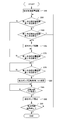
- FIG. 2 is a flowchart showing a water supply control process of the water supply control device according to the first embodiment.
- the control unit 9 determines whether or not a first water level that is a specific water level is detected by the first water level detection electrode rod 6. (Step S15).
- the first water level is, for example, a possibility that the first water pipe 21a or the second water pipe 21b may be damaged due to overheating due to a drop in the water level in the first water pipe 21a or the second water pipe 21b. Including water levels that require water.
- step S15 when the first water level is detected by the first water level detection electrode rod 6 (no water), the control unit 9 proceeds to step S25. On the other hand, if the first water level is not detected in the first water level detection electrode rod 6 in step S15 (there is water), the control unit 9 has detected the first water level by the second water level detection electrode rod 7. It is determined whether or not (step S20). In step S20, when the first water level is not detected (there is water), the first water pipe 21a and the second water pipe 21b both satisfy the first water level. Returning to S15, the determination of detection of the first water level by the first water level detection electrode rod 6 and the second water level detection electrode rod 7 is repeated.
- the control unit 9 sets the activation time (T1) of the water supply pump 8 (step S25).
- the activation time (T1) is set based on the steam pressure of the first water pipe 21a or the second water pipe 21b in which the first water level is detected and the temperature of water supplied by the water supply pump 8 (water supply temperature).
- the control unit 9 has a case where the feed water temperature is 40 degrees or less and 41 degrees or more.
- the activation time (T1) is set so that the water supply pump 8 is activated for 7 seconds. That is, the control unit 9 is set to supply water to the boiler can body 20 for 7 seconds.
- the control unit 9 The water supply pump 8 is started for 14 seconds, and when the water supply temperature is 41 degrees or more, the start time (T1) is set so that the water supply pump 8 is started for 7 seconds. That is, when the feed water temperature is 40 degrees or less, the control unit 9 supplies water to the boiler can body 14 for 14 seconds, and when the feed water temperature is 41 degrees or more, the control section 9 is set to feed water to the boiler can body 20 for 7 seconds. .
- the control unit 9 performs 21 seconds when the feed water temperature is 40 degrees or less.
- the start time (T1) is set so that the feed water pump 8 is started for 7 seconds. That is, the control unit 9 is set to supply water for 21 seconds when the water supply temperature is 40 degrees or less, and to supply water for 7 seconds when the water supply temperature is 41 degrees or more.
- step S30 When the activation time (T1) is set, the control unit 9 activates the water supply pump 8 (step S30). In step S30, when the water supply pump 8 is activated, the control unit 9 determines whether the activation time (T1) has elapsed (step S35). If it is determined in step S35 that the predetermined activation time (T1) has elapsed, the process proceeds to step S40, and the control unit 9 stops the water supply pump 8 (step S40). On the other hand, if it is determined in step S35 that the activation time (T1) has not elapsed, the determination is repeated until the activation time (T1) has elapsed.
- step S45 when the water supply pump 8 is stopped by the control unit 9 in step S40, the control unit 9 determines whether or not there is an instruction to stop the water supply control device 5 (step S45). In step S45, when there is an instruction to stop the water supply control device 5, the control unit 9 ends the water supply control process. On the other hand, when there is no stop instruction in the water supply control device 5, the process returns to step S15 and the above control is repeated.
- the water supply control device 5 is based on the steam pressure of the first water pipe 21a or the second water pipe 21b in which the first water level is detected and the temperature of water supplied by the water supply pump 8 (water supply temperature).
- the starting time of the feed water pump 8 is set. For this reason, for example, even when the boiler device 1 is repeatedly activated and stopped in a short time, even after the boiler device 1 is started immediately after the stop, the first water level is detected by the water level detection electrode rod, and then based on the steam pressure and the feed water temperature. By supplying water for a predetermined time, it becomes possible to prevent the water level from becoming higher than the target water level.
- the water supply control device 5 detects the water level in the pipe inside the water pipe by using the two electrode rods of the first water level detection electrode rod 6 and the second water level detection electrode rod 7.
- the first water level detection electrode rod 6 and the second water level detection electrode rod 7 are attached to a water pipe disposed in a place where overheating is likely to occur. Therefore, for example, even when the superheated water pipes differ depending on the location of the water pipes, the first water level detection electrode rod 6 and the second water level detection electrode rod 7 are attached to the water pipes that are likely to overheat. Since water is supplied based on easy water pipes, it is possible to prevent water pipes from being damaged due to overheating.
- FIG. 3 is a schematic diagram showing a schematic configuration of a boiler apparatus having a water supply control device according to a second embodiment of the present invention.
- the boiler apparatus 1A having the water supply control apparatus 5A according to the second embodiment has the same configuration as the boiler apparatus 1 according to the first embodiment.
- the water supply control device 5A according to the second embodiment is different from the first embodiment in the control method in the control unit 9A of the water supply control device 5A.
- the boiler device 1A is mainly configured by a boiler body 2, a steam / water separator 3, a water level detection device 4, and a water supply control device 5A.
- the boiler body 2 includes a boiler can body 20, a plurality of water pipes 21, a lower header 22, an upper header 23, and a heating burner 24.
- the water supply control device 5A includes a first water level detection electrode rod 6, a second water level detection electrode rod 7, a water supply pump 8, and a control unit 9A.
- the control unit 9A is connected to the first water level detection electrode rod 6, the second water level detection electrode rod 7, and the water supply pump 8 through the line 9a.
- the control unit 9A activates the water supply pump 8 when the second water level, which is a specific water level by the first water level detection electrode rod 6 or the second water level detection electrode rod 7, is not detected due to a decrease in can water.
- the water level rises due to the activation of the water supply pump and the second water level is detected by the first water level detection electrode rod 6 and the second water level detection electrode rod 7, the steam in the first water pipe 21a and the second water pipe 21b is detected.
- the start time of the feed water pump 8 after detection of the second water level (hereinafter referred to as “remaining start time”) is determined, and a predetermined start remaining Water supply control is performed so as to satisfy the target water level by stopping the water supply pump 8 after a lapse of time.
- FIG. 4 is a flowchart showing a water supply control process of the water supply control device according to the second embodiment.
- a 2nd water level contains the target water level in the case of supplying water to the boiler main body 2, for example.
- step S55 if the second water level is not detected by the first water level detection electrode rod 6 (no water), the process proceeds to step S65.
- step S55 when the second water level is detected by the first water level detection electrode rod 6 (with water), the control unit 9 determines whether the second water level is detected by the second water level detection electrode rod 7 or not. Is determined (step S60).
- Step S60 if the second water level is not detected by the second water level detection electrode rod 7 (no water), the process proceeds to Step S65.
- step S60 when the second water level is detected by the second water level detection electrode rod 7 (with water), both the first water pipe 21a and the second water pipe 21b satisfy the second water level. Therefore, the control unit 9 returns to step S55 and repeats the determination of the detection of the second water level by the first water level detection electrode rod 6 and the second water level detection electrode rod 7.
- step S65 when the second water level is not detected by the first water level detection electrode rod 6 in step S55, or when the second water level is detected by the second water level detection electrode rod 7 in step S60, the control unit 9A. Activates the water supply pump 8 (step S65).
- step S70 determines whether or not the second water level is detected by the first water level detection electrode rod 6 (step S70).
- step S70 when the second water level is not detected by the first water level detection electrode rod 6 (no water), the control unit 9A determines until the second water level is detected by the first water level detection electrode rod 6. repeat.
- the process proceeds to step S75.
- step S75 if the second water level is not detected by the second water level detection electrode rod 7 (no water), the control unit 9A determines until the second water level is detected by the second water level detection electrode rod 7. repeat. On the other hand, when the second water level is detected by the second water level detection electrode rod 7 (with water), the process proceeds to step S80.
- the control unit 9A sets the remaining activation time (T2) of the water supply pump 8.
- the setting of the remaining activation time (T2) is set based on the steam pressure of the first water pipe 21a or the second water pipe 21b in which the second water level is detected and the temperature of water supplied by the water supply pump 8 (water supply temperature). .
- the control unit 9A has a case where the feed water temperature is 40 degrees or less and 40 degrees or more.
- the remaining activation time (T2) is set so that the water supply pump 8 is activated for 7 seconds. That is, the control unit 9A sets the boiler can body 20 to supply water for 7 seconds.
- the control unit 9A When the steam pressure of the first water pipe 21a or the second water pipe 21b in which the second water level is detected is 0.79 to 0.89 MPa, the control unit 9A The water supply pump 8 is started for 14 seconds, and when the water supply temperature is 41 degrees or more, the remaining activation time (T2) is set so that the water supply pump 8 is started for 7 seconds. That is, the control unit 9A sets the boiler can body 20 to supply water for 14 seconds when the feed water temperature is 40 degrees or less, and to supply water to the boiler can body 20 for 7 seconds when the feed water temperature is 41 degrees or more. .
- the control unit 9A is 21 seconds when the feed water temperature is 40 degrees or less.
- the remaining start time (T2) is set so that the feed pump 8 is started for 7 seconds. That is, the control unit 9A sets to supply water for 21 seconds when the water supply temperature is 40 degrees or less, and to supply water for 7 seconds when the water supply temperature is 41 degrees or more.
- step S80 the control unit 9A determines whether the remaining activation time (T2) has elapsed since the second water level was detected (step S85). If it is determined in step S85 that the remaining activation time (T2) has elapsed, the process proceeds to step S90, and the water supply pump 8 is stopped (step S90). On the other hand, if it is determined in step S85 that the remaining activation time (T2) has not elapsed, the determination is repeated until the remaining activation time (T2) has elapsed.
- step S95 when the water supply pump 8 is stopped by the control unit 9A in step S90, the control unit 9A determines whether or not there is an instruction to stop the water supply control device 5A (step S95). In step S95, when there is an instruction to stop the water supply control device 5A, the control unit 9A ends the water supply control process. On the other hand, if there is no instruction to stop the water supply control device 5A, the process returns to step S55 and the above control is repeated.
- the water supply control device 5A is based on the steam pressure of the first water pipe 21a or the second water pipe 21b in which the second water level is detected and the temperature of water supplied by the water supply pump 8 (water supply temperature).
- the starting time of the feed water pump 8 is set. For this reason, for example, even when the boiler device 1A is repeatedly activated and stopped in a short time, even when the boiler device 1A is started immediately after the stop, the second water level is detected by the water level detection electrode rod, and then based on the steam pressure and the feed water temperature. By supplying water for a predetermined time, it becomes possible to prevent the water level from becoming higher than the target water level.
- the water supply control device 5A detects the water level in the pipe inside the water pipe by using the two electrode bars of the first water level detection electrode bar 6 and the second water level detection electrode bar 7.
- the first water level detection electrode rod 6 and the second water level detection electrode rod 7 are attached to a water pipe disposed in a place where overheating is likely to occur. Therefore, for example, even when the superheated water pipes differ depending on the location of the water pipes, the first water level detection electrode rod 6 and the second water level detection electrode rod 7 are attached to the water pipes that are likely to overheat. Since water is supplied based on easy water pipes, it is possible to prevent water pipes from being damaged due to overheating.
- a plurality of water pipes 21 are erected at predetermined intervals in the circumferential direction of the boiler can body 20, a combustion chamber 25 is provided at a substantially central portion, and a heating burner 24 is disposed above the combustion chamber 25.
- the present invention is not limited to this.
- it is good also as a structure which arrange
- the first water pipe 21a to which the first water level detection electrode rod 6 is attached is disposed in the vicinity of the heating burner 24, and the second water pipe 21b to which the second water level detection electrode rod is attached is a heating burner.
- the first water pipe 21a to which the first water level detection electrode rod is attached and the second water pipe 21b to which the second water level detection electrode rod is attached are arranged at places where there is a possibility of overheating each other. That's fine. Examples of places where there is a possibility of overheating include the vicinity of the heating burner 24 and the vicinity of a flue (not shown).
- a water supply control device may be configured using one water detection electrode rod, or a water supply control device may be configured using a plurality of water level detection electrode rods.
Landscapes
- Engineering & Computer Science (AREA)
- Physics & Mathematics (AREA)
- Thermal Sciences (AREA)
- Mechanical Engineering (AREA)
- General Engineering & Computer Science (AREA)
- Chemical & Material Sciences (AREA)
- Combustion & Propulsion (AREA)
- Measurement Of Levels Of Liquids Or Fluent Solid Materials (AREA)
- Control Of Steam Boilers And Waste-Gas Boilers (AREA)
Abstract
Dispositif de commande d'alimentation en eau, comportant des électrodes de détection du niveau d'eau installées dans un tube à eau logé dans un corps de chaudière et capables de détecter des niveaux d'eau particuliers à l'intérieur du tube à eau, une pompe d'alimentation en eau servant à alimenter en eau le corps de chaudière, et un composant de commande servant à commander le démarrage et l'arrêt de la pompe d'alimentation en eau. Le composant de commande démarre de façon appropriée la pompe d'alimentation en eau lorsque l'électrode de détection du niveau d'eau détecte le niveau d'eau particulier, détermine le temps de marche de la pompe d'alimentation en eau en fonction de la pression dans le tube à eau et de la température de l'eau introduite dans le tube à eau, et arrête la pompe d'alimentation en eau après que le temps de marche s'est écoulé.
Applications Claiming Priority (2)
| Application Number | Priority Date | Filing Date | Title |
|---|---|---|---|
| JP2008245631A JP5277835B2 (ja) | 2008-09-25 | 2008-09-25 | 給水制御装置 |
| JP2008-245631 | 2008-09-25 |
Publications (1)
| Publication Number | Publication Date |
|---|---|
| WO2010035541A1 true WO2010035541A1 (fr) | 2010-04-01 |
Family
ID=42059550
Family Applications (1)
| Application Number | Title | Priority Date | Filing Date |
|---|---|---|---|
| PCT/JP2009/058192 Ceased WO2010035541A1 (fr) | 2008-09-25 | 2009-04-24 | Dispositif de commande d’alimentation en eau |
Country Status (3)
| Country | Link |
|---|---|
| JP (1) | JP5277835B2 (fr) |
| TW (1) | TW201013120A (fr) |
| WO (1) | WO2010035541A1 (fr) |
Cited By (1)
| Publication number | Priority date | Publication date | Assignee | Title |
|---|---|---|---|---|
| US20140345545A1 (en) * | 2011-12-22 | 2014-11-27 | Miura Co., Ltd. | Boiler |
Families Citing this family (5)
| Publication number | Priority date | Publication date | Assignee | Title |
|---|---|---|---|---|
| JP5671915B2 (ja) * | 2010-09-29 | 2015-02-18 | 三浦工業株式会社 | ボイラ装置 |
| JP2012072992A (ja) * | 2010-09-29 | 2012-04-12 | Miura Co Ltd | 給水制御装置及びボイラ |
| JP5811610B2 (ja) * | 2011-06-14 | 2015-11-11 | 三浦工業株式会社 | ボイラ装置 |
| JP5534251B2 (ja) * | 2012-01-31 | 2014-06-25 | 三浦工業株式会社 | ボイラ |
| CN106125781A (zh) * | 2016-08-28 | 2016-11-16 | 华北电力大学(保定) | 一种基于LMIs的汽包水位控制系统设计方法 |
Citations (3)
| Publication number | Priority date | Publication date | Assignee | Title |
|---|---|---|---|---|
| JPH0245309U (fr) * | 1988-09-16 | 1990-03-28 | ||
| JPH0292412U (fr) * | 1988-12-27 | 1990-07-23 | ||
| JPH07127810A (ja) * | 1993-06-18 | 1995-05-16 | Ebara Res Co Ltd | 多管式貫流ボイラの過熱防止装置 |
-
2008
- 2008-09-25 JP JP2008245631A patent/JP5277835B2/ja active Active
-
2009
- 2009-04-24 WO PCT/JP2009/058192 patent/WO2010035541A1/fr not_active Ceased
- 2009-05-19 TW TW98116502A patent/TW201013120A/zh unknown
Patent Citations (3)
| Publication number | Priority date | Publication date | Assignee | Title |
|---|---|---|---|---|
| JPH0245309U (fr) * | 1988-09-16 | 1990-03-28 | ||
| JPH0292412U (fr) * | 1988-12-27 | 1990-07-23 | ||
| JPH07127810A (ja) * | 1993-06-18 | 1995-05-16 | Ebara Res Co Ltd | 多管式貫流ボイラの過熱防止装置 |
Cited By (1)
| Publication number | Priority date | Publication date | Assignee | Title |
|---|---|---|---|---|
| US20140345545A1 (en) * | 2011-12-22 | 2014-11-27 | Miura Co., Ltd. | Boiler |
Also Published As
| Publication number | Publication date |
|---|---|
| TW201013120A (en) | 2010-04-01 |
| JP5277835B2 (ja) | 2013-08-28 |
| JP2010078204A (ja) | 2010-04-08 |
Similar Documents
| Publication | Publication Date | Title |
|---|---|---|
| JP5277835B2 (ja) | 給水制御装置 | |
| JP4636200B2 (ja) | 給水制御装置 | |
| KR101329371B1 (ko) | 수위검출용 전극봉, 수위검출방법, 보일러의 수위제어방법및 기수분리기의 수위제어방법 | |
| KR101541716B1 (ko) | 전극식 온수 및 스팀 보일러 시스템 | |
| KR200326835Y1 (ko) | 전기 스팀보일러 | |
| JP2011106739A (ja) | 給水制御装置 | |
| JP2014219117A (ja) | ボイラ | |
| KR101187929B1 (ko) | 스팀보일러 | |
| JP2008241182A (ja) | 電極式水位検出器付きボイラ | |
| JP5671915B2 (ja) | ボイラ装置 | |
| JP5239675B2 (ja) | 液位検出装置 | |
| WO2010032512A1 (fr) | Dispositif de commande d’alimentation en eau | |
| JP2016061490A (ja) | ボイラ | |
| JP2002147708A (ja) | ボイラの給水制御方法 | |
| JP2010151360A (ja) | 電気ボイラ | |
| WO2025191771A1 (fr) | Chaudière à cycle ouvert | |
| JP4071671B2 (ja) | ボイラの水位制御装置 | |
| WO2025191772A1 (fr) | Chaudière de type à électrode | |
| JP2010078587A (ja) | 液位検出装置 | |
| CN204730166U (zh) | 蒸汽锅炉 | |
| JP2015203691A (ja) | 電極棒の動作判定方法及び液体収容装置 | |
| KR200461214Y1 (ko) | 보일러 및 온수기용 일체형 감지센서 | |
| JPH11281003A (ja) | ボイラの燃焼制御装置 | |
| JPH0330643Y2 (fr) | ||
| JP2668262B2 (ja) | ボイラーの水位制御方法 |
Legal Events
| Date | Code | Title | Description |
|---|---|---|---|
| 121 | Ep: the epo has been informed by wipo that ep was designated in this application |
Ref document number: 09815959 Country of ref document: EP Kind code of ref document: A1 |
|
| NENP | Non-entry into the national phase |
Ref country code: DE |
|
| 122 | Ep: pct application non-entry in european phase |
Ref document number: 09815959 Country of ref document: EP Kind code of ref document: A1 |