WO2010050008A1 - Émetteur et récepteur de puissance électrique à région de fresnel variable en fréquence, et système de transmission de puissance électrique - Google Patents
Émetteur et récepteur de puissance électrique à région de fresnel variable en fréquence, et système de transmission de puissance électrique Download PDFInfo
- Publication number
- WO2010050008A1 WO2010050008A1 PCT/JP2008/069625 JP2008069625W WO2010050008A1 WO 2010050008 A1 WO2010050008 A1 WO 2010050008A1 JP 2008069625 W JP2008069625 W JP 2008069625W WO 2010050008 A1 WO2010050008 A1 WO 2010050008A1
- Authority
- WO
- WIPO (PCT)
- Prior art keywords
- frequency
- transmitter
- receiver
- power transmission
- antenna
- Prior art date
- Legal status (The legal status is an assumption and is not a legal conclusion. Google has not performed a legal analysis and makes no representation as to the accuracy of the status listed.)
- Ceased
Links
Images










Classifications
-
- H—ELECTRICITY
- H04—ELECTRIC COMMUNICATION TECHNIQUE
- H04B—TRANSMISSION
- H04B5/00—Near-field transmission systems, e.g. inductive or capacitive transmission systems
- H04B5/20—Near-field transmission systems, e.g. inductive or capacitive transmission systems characterised by the transmission technique; characterised by the transmission medium
- H04B5/22—Capacitive coupling
-
- H—ELECTRICITY
- H02—GENERATION; CONVERSION OR DISTRIBUTION OF ELECTRIC POWER
- H02J—ELECTRIC POWER NETWORKS; CIRCUIT ARRANGEMENTS OR SYSTEMS FOR SUPPLYING OR DISTRIBUTING ELECTRIC POWER; SYSTEMS FOR STORING ELECTRIC ENERGY
- H02J50/00—Circuit arrangements or systems for wireless supply or distribution of electric power
- H02J50/20—Circuit arrangements or systems for wireless supply or distribution of electric power using microwaves or radio frequency waves
-
- H—ELECTRICITY
- H02—GENERATION; CONVERSION OR DISTRIBUTION OF ELECTRIC POWER
- H02J—ELECTRIC POWER NETWORKS; CIRCUIT ARRANGEMENTS OR SYSTEMS FOR SUPPLYING OR DISTRIBUTING ELECTRIC POWER; SYSTEMS FOR STORING ELECTRIC ENERGY
- H02J50/00—Circuit arrangements or systems for wireless supply or distribution of electric power
- H02J50/20—Circuit arrangements or systems for wireless supply or distribution of electric power using microwaves or radio frequency waves
- H02J50/23—Circuit arrangements or systems for wireless supply or distribution of electric power using microwaves or radio frequency waves characterised by the type of transmitting antennas, e.g. directional array antennas or Yagi antennas
-
- H—ELECTRICITY
- H02—GENERATION; CONVERSION OR DISTRIBUTION OF ELECTRIC POWER
- H02J—ELECTRIC POWER NETWORKS; CIRCUIT ARRANGEMENTS OR SYSTEMS FOR SUPPLYING OR DISTRIBUTING ELECTRIC POWER; SYSTEMS FOR STORING ELECTRIC ENERGY
- H02J50/00—Circuit arrangements or systems for wireless supply or distribution of electric power
- H02J50/40—Circuit arrangements or systems for wireless supply or distribution of electric power using two or more transmitting or receiving devices
-
- H—ELECTRICITY
- H02—GENERATION; CONVERSION OR DISTRIBUTION OF ELECTRIC POWER
- H02J—ELECTRIC POWER NETWORKS; CIRCUIT ARRANGEMENTS OR SYSTEMS FOR SUPPLYING OR DISTRIBUTING ELECTRIC POWER; SYSTEMS FOR STORING ELECTRIC ENERGY
- H02J50/00—Circuit arrangements or systems for wireless supply or distribution of electric power
- H02J50/80—Circuit arrangements or systems for wireless supply or distribution of electric power involving the exchange of data, concerning supply or distribution of electric power, between transmitting devices and receiving devices
-
- H—ELECTRICITY
- H04—ELECTRIC COMMUNICATION TECHNIQUE
- H04B—TRANSMISSION
- H04B5/00—Near-field transmission systems, e.g. inductive or capacitive transmission systems
- H04B5/20—Near-field transmission systems, e.g. inductive or capacitive transmission systems characterised by the transmission technique; characterised by the transmission medium
- H04B5/24—Inductive coupling
-
- H—ELECTRICITY
- H04—ELECTRIC COMMUNICATION TECHNIQUE
- H04B—TRANSMISSION
- H04B5/00—Near-field transmission systems, e.g. inductive or capacitive transmission systems
- H04B5/70—Near-field transmission systems, e.g. inductive or capacitive transmission systems specially adapted for specific purposes
- H04B5/79—Near-field transmission systems, e.g. inductive or capacitive transmission systems specially adapted for specific purposes for data transfer in combination with power transfer
Definitions
- the present invention relates to a system, an apparatus, and a transmission method for transmitting power using electromagnetic waves, particularly in a Fresnel region where an electrostatic field and an induction field play a major role in energy interaction of electromagnetic fields as compared to a radiation field.
- the present invention relates to a power transmission system, a power transmission device, and a power transmission system suitable for power transmission.
- the receiver uses the radiated field component of the electromagnetic wave emitted from the transmitter, and the receiver captures the electromagnetic field and converts it into an alternating current as a power source by rectification.
- basic RFID There has been a technology called “basic RFID” that obtains usable power (for example, see Non-Patent Document 1).
- RFID handbook 2nd edition written by Klaus Finkenzella, translated by Institute of Software Engineering, published by Nikkan Kogyo Shimbun, May 2004)
- Non-Patent Document 1 The power used by RFID receivers is currently about several microwatts, which is orders of magnitude smaller than the order of several watts to several tens of watts, which is the power required to operate general consumer devices.
- the energy distribution of the electromagnetic field emitted from the transmitter to the space is composed of three elements, an electrostatic field, an induction field, and a radiation field, depending on the attenuation method associated with the distance from the emission point. Decays to the power and power. The amount of energy in each field in the immediate vicinity of the radiation point of power decreases by an order of magnitude in the order of electrostatic field, induction field, and radiation field.
- the electromagnetic field related to wireless power transmission used in the prior art RFID is mainly a radiation field or an induction field, and power transmission on the order of several watts to several tens of watts that enables operation of consumer equipment has not been realized.
- the electrostatic field allows power transmission on the order of several watts, but in actual use it can be remotely controlled. It is not sufficient to improve convenience related to installation and movement of information equipment by transmitting power wirelessly without sending. For example, considering the actual usage of information equipment including imaging equipment at home or in the office, transmission of electric power to replace a remote wired power supply line having a distance of 1 meter inside and outside is required.
- An object of the present invention is to realize practical remote wireless power transmission capable of eliminating the conventional wired power supply line by using all fields of the electrostatic field, induction field, and radiation field of the electromagnetic field.
- An example of a representative example of the present invention is as follows. That is, since the frequency variable Fresnel region power transmission system of the present invention uses an electrostatic field and an induction field for power transmission at the same time, a capacitive element and an induction are used for an antenna for transmitting power by electromagnetic waves between a transmitter and a receiver. An element is formed, the transmission frequency of the transmitter is variable, the electromagnetic wave transmitted from the transmitter and reflected from the receiver is modulated, and the modulated reflected wave is used between the transmitter and the receiver. It is characterized by controlling power transmission efficiency.
- the frequency variable Fresnel domain power transmitter of the present invention is used in the frequency variable Fresnel domain power transmission system described above, and includes an antenna, a frequency variable carrier generator, a directional coupling, a demodulation circuit, and a control circuit.
- the received reflected wave is separated by a directional coupler, the reflected wave is demodulated, and the frequency of the carrier wave generator is made variable using the demodulated signal.
- the frequency variable Fresnel domain power receiver of the present invention is used in the frequency variable Fresnel domain power transmission system described above, and includes an antenna, a switching element inserted in parallel with the antenna, a control circuit, a memory, and a rectifier circuit.
- the control circuit is characterized in that the switching element is turned on / off at a fixed timing stored in advance in a memory.
- the wireless power transmission system operating in the Fresnel region that is one of the present invention, since all of the electrostatic field, induction field, and radiation field generated in space when performing power transmission by electromagnetic waves, it is a conventional technique. It is possible to transmit power more efficiently than a wireless system that focuses on a single field.
- FIG. 6B is a frequency spectrum of the configuration of FIG. 6A and shows the relationship between frequency and amplitude H1.
- FIG. 6B is a frequency spectrum of the configuration of FIG. 6A and shows the relationship between frequency and amplitude H2. It is a perspective view which shows the structural example of the antenna for frequency variable Fresnel area
- FIG. 11B is a frequency spectrum of the configuration of FIG. 11A and shows the relationship between frequency and amplitude H1.
- FIG. 11B is a frequency spectrum of the configuration of FIG. 11A and shows the relationship between frequency and amplitude H2.
- Smoothing circuit 45.
- an equivalent circuit network composed of a capacitive element and an inductive element contributes to high-efficiency energy transmission in the energy transmission using the electrostatic field and the inductive field as the main object, which is the object of the present invention.
- Such an equivalent circuit network includes a resonant circuit formed of an inductive element and a capacitive element, so that at the resonance point of the resonant circuit, the reactance component of the equivalent circuit network is minimized and the energy stored in the space is minimized. Maximum energy transfer from the transmitter to the receiver is achieved.
- the equivalent network formed in the space including the transmitter and the receiver can be expressed by an impedance function
- the reactance value of the network is a function of frequency. Therefore, by changing the frequency of the electromagnetic field reaching the receiver from the transmitter, the reactance value constituting the equivalent circuit network can be changed.
- Changing the frequency of the transmitter means that the frequency of the electromagnetic field radiated from the transmitter to the space is spread over a wide area. In general, there are many wireless systems that use electromagnetic fields. Therefore, it is desirable that the number of frequencies used for wireless power transmission be as small as possible.
- the frequency range changed by the transmitter is narrow.
- the reactance value forming the equivalent network greatly changes with the change in the frequency.
- the Q value of the reactance is high, and may be realized by providing a high Q capacitor and a high Q inductor in the space including the transmitter and the receiver.
- An antenna plays a role of exchanging energy of electromagnetic waves between a receiver or a transmitter and a space, and a circuit including a high-Q capacitor and a high-Q inductor having electrical characteristics in a frequency region in which the antenna is used. It may be the same as the operation.
- a predetermined two-dimensional region is divided into minute rectangular regions, and a combination of whether or not there is a conductor in the minute rectangular region and a set of the minute rectangular conductors present in the vicinity of each other.
- the combination is searched exhaustively and an appropriate element value of the high Q capacitor or the high Q inductor is obtained by a local optimization method. It is possible to find out.
- the wireless power transmission efficiency corresponding to the change in the electrical environment of the space including the transmitter and the receiver is optimized.
- a reference signal for changing the frequency of the transmitter is obtained, the control can be realized in real time, and as a result, adaptive control of the wireless power transmission efficiency becomes possible.
- a switching element is inserted in parallel with the antenna of the receiver, and the switching element is turned on / off at a predetermined timing.
- the antenna can alternately switch the binary load impedance, so that the reflection coefficient of the antenna with respect to the external electromagnetic field changes, and as a result, the reflected wave reaching the transmitter is subjected to amplitude modulation, Sideband waves having different frequencies from the transmission frequency are generated.
- the electromagnetic field component emitted from the transmitter and reflected by the receiver is weak, the sideband and the transmission frequency are different in frequency, and can be easily detected by the conventional technique.
- One of such conventional techniques is an RFID receiver reflected wave identification method using backscattering, the details of which are described in Non-Patent Document 1 described above.
- control information is transmitted to a wireless line formed by a transmitter and a receiver in order to perform optimization control by adaptive type of wireless power transmission efficiency.
- the wireless power transmission system of the present invention forms a line that enables information transmission. Utilizing this characteristic, it is possible to realize so-called “coexistence transmission of power and information” in which not only power but also information is transmitted by superimposing some information on the electromagnetic wave transmitted by mounting a modulator in the transmitter. it can. In order to realize practically convenient wireless power transmission using the Fresnel region, the wavelength of the electromagnetic wave to be used must be increased.
- the frequency is 33 MHz assuming a wavelength of about 1/10 which is a wavelength region where an induction field and an electrostatic field can be utilized, and transmission of several Mbps is considered when ordinary AM modulation is considered.
- "Simultaneous transmission of power and information" at speed is feasible.
- the modulation frequency of the transmitter needs to be sufficiently separated from the frequency of the sideband used for the application control. Since the signal for normal control does not need to have a large amount of information, the transmission speed of the signal superimposed on the electromagnetic wave transmitted by the transmitter is larger than the transmission speed of the signal superimposed on the reflected wave of the electromagnetic wave by the receiver. That's fine.
- the power obtained from the antenna using the technology of the present invention is high-frequency AC power, and it is necessary to convert the power into DC power by rectification in order to use this power as a power source.
- the frequency band used in the Fresnel region is tens of MHz while the required power is on the order of several watts.
- a semiconductor device that converts AC power into DC power is a diode.
- a diode has an inversely proportional operating frequency and operating breakdown voltage.
- a diode operating in a low-loss and high-frequency region can be realized by miniaturizing the structure, but the reverse withstand voltage power decreases with the miniaturization of the structure.
- the power after rectification is direct current power, and it is essentially not necessary to consider the combined loss related to the phase mismatch unique to the high frequency and the transmission loss related to the ohmic loss of the power combined line when combining the power. Therefore, a rectifier circuit consisting of diodes, capacitors, and load resistors and a smoothing circuit are dispersedly arranged at a plurality of locations of the antenna, and the DC power that is the output of each smoothing circuit is coupled to a conductor that is different from the conductor constituting the antenna. It is possible to achieve a high rectification efficiency by synthesizing with. At this time, the coupling line is arranged along the back surface of the minute conductor constituting the antenna so as not to affect the antenna characteristics.
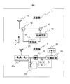
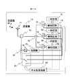
- FIG. 1 is a diagram showing a configuration of an embodiment of a frequency variable Fresnel region power transmission system according to the present invention.
- a directional coupler 12 is coupled to a first antenna 11 and a frequency variable to the directional coupler 12.
- the carrier wave generator 13 is coupled in the direction in which the signal is supplied to the antenna 11, and the frequency variable carrier wave generator 13 is controlled using the demodulated signal of the demodulator 15 to which the signal is sent from the antenna 11 via the directional coupler 12.
- a control circuit 25 that uses the output of the smoothing circuit 24 as a power source includes a memory 26, and controls a switching circuit 23 that includes a switching element inserted in parallel with the second antenna 21. It is made from the receiver 2.
- the output of the frequency variable carrier wave generator 13 sent from the transmitter 1 becomes the input of the second antenna 21 of the receiver 2 and is rectified by the rectifier circuit 22, smoothed by the smoothing circuit 24, and drives the control circuit 25 to perform the control.
- the circuit 25 opens and closes the switching circuit 23 according to a time sequence written in the memory 26 in advance. Since the load impedance of the second antenna 21 is changed by opening and closing the switching circuit 23, the electromagnetic wave reflected by the second antenna 21 is modulated according to the data in the memory 26 and transmitted from the first antenna 11. This information is taken into the machine 1 and provided to the control circuit 14 by the demodulator 15 via the directional coupler 12.
- the control circuit 14 uses the demodulated information to change the carrier frequency of the frequency variable carrier generator 13 so that the reception power of the receiver 2 is maximized.
- the directional coupler 12 can be realized by a circulator, a hybrid line, a half-wave coupler, or the like according to the frequency of the electromagnetic wave transmitted by the frequency variable Fresnel region power transmission system.
- the switching circuit 23 can be realized using a transistor, a pin diode, or the like.
- the second antenna 21 provided in the receiver 2 is loaded with a reactance element, the self-impedance of the antenna changes with the change of the carrier frequency, and the electromagnetic wave transmitted from the transmitter 1 is transmitted.
- the matching state between the space near the machine 2 and the rectifier circuit 22 inside the receiver 2 can be adaptively controlled.
- the matching state between the two is good, the amount of the electromagnetic wave reflected from the second antenna 21 is reduced, so that the on / off ratio of the reflected wave generated by turning on / off the switching circuit 23 is also increased.
- the degree of modulation applied to the reflected wave increases, and the amplitude of the sideband inside the reflected wave increases.
- control circuit 14 of the transmitter 1 controls the carrier frequency of the frequency variable carrier generator 13 so as to maximize the sideband amplitude, power transmission from the transmitter 1 to the receiver 2 is dynamically optimized. In other words, adaptive optimization of power transmission efficiency can be realized.
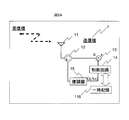
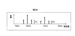
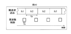
- FIG. 2 shows another embodiment (FIG. 2A) of the structure of the transmitter used in the Fresnel area power transmission system of FIG. 1 which is an embodiment of the frequency variable Fresnel area power transmission system according to the present invention, and the frequency of the received reflected wave. It is a figure which shows the time chart (FIG. 2C) of the time change (FIG. 2B) of a spectrum, and operation
- the control circuit 14 includes a temporary memory 116.
- the control circuit 14 of the transmitter 1 has a maximum allowable frequency fmax, a minimum allowable frequency fmin, a frequency update value ⁇ f, and a natural center frequency fc0 that are predetermined in the temporary storage 116.
- the control circuit 14 is first initialized. As a procedure, the carrier frequency of the frequency variable carrier generator 13 is set to fc0, the provisional maximum value of the sideband is set to 0, and the value of the provisional direction of frequency change is positive. When the amplitude of the sideband of the received reflected wave is compared with the provisional maximum value and a large amplitude is obtained, the carrier frequency of the frequency variable carrier generation device 13 is advanced in the provisional direction of frequency change by ⁇ f. The provisional maximum value is updated, and when a small amplitude is obtained, the carrier frequency of the frequency variable carrier generation device 13 is advanced in the direction opposite to the provisional direction of the frequency change by ⁇ f to reverse the provisional direction.
- the frequency spectrum of the electromagnetic wave used by the frequency variable Fresnel region power transmission system dynamically changes between fmax and fmin as shown in FIG. 2B.
- the time chart of the control circuit 14 and the frequency variable carrier wave generator 13 performs a control procedure for updating the frequency of the frequency variable carrier wave generator 13 during the time Tc at every fixed period Tp. Do.
- the frequency variable carrier generator 13 changes the transmission frequency after the control procedure is completed. If the frequency to be updated is the same as the previous frequency, the frequency variable carrier wave generator 13 transmits an electromagnetic wave at the same frequency. In the example of FIG. 2C, the second frequency update is not performed.
- adaptive optimization of power transmission efficiency can be realized with a specific control algorithm using the conventional automatic control technology.
- FIG. 4 is a diagram showing the structure of another embodiment of the frequency variable Fresnel area power transmission system according to the present invention. 1 differs from the base station of the embodiment of FIG. 1 in that the transmitter 1 includes a modulator 16 and an arithmetic circuit 17, and the receiver 2 includes an arithmetic circuit 28, a demodulator 27, a coupler 29, and a filter 219.
- the modulator 16 is inserted between the directional coupler 12 and the variable frequency carrier generator 13, the arithmetic circuit 17 centrally manages the control circuit 14, the demodulator 15 and the modulator 16, and the arithmetic circuit 28 is a memory.
- the control circuit 25 When the control circuit 25 is controlled using the information 26, a part of the energy of the electromagnetic wave received by the antenna 21 branched by the coupler 29 inserted between the second antenna 21 and the rectifier circuit 22 is filtered 219. Centrally manages the demodulator 27 that is input via the.
- the modulation frequency of the modulator 16 is set higher than the switching frequency of the switching circuit 23 in which the receiver 2 modulates the reflected wave from the transmitter 1.
- the filter 219 as a wide-pass filter, information superimposed on the electromagnetic wave transmitted from the transmitter 1 by the modulator 16 can be demodulated by the demodulator 27 of the receiver 2, so that wireless power and information are compatible. There is an effect of realizing transmission.
- FIG. 5 shows another embodiment of the variable frequency Fresnel region power transmission system according to the present invention.
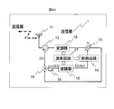
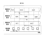
- FIG. 5 shows the transmitter structure (FIG. 5A) of the variable frequency Fresnel region power transmission system of FIG.
- FIG. 5B is a diagram showing a time chart (FIG. 5C) of the operation of the control circuit (FIG. 5B).
- the arithmetic circuit 17 selects one of the two sidebands of the carrier wave with the smaller detuning frequency and supplies it to the control circuit 14 as a control signal for the frequency variable carrier wave generator 13.
- the control method of the frequency variable carrier wave generator 13 is the same as that of the embodiment of FIG.
- the receiver 2 can obtain some information together with the power transmission.
- the arithmetic circuit 17 adds information to the modulation signal of the modulator 16, wirelessly compatible transmission of power and information becomes possible.
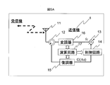
- FIG. 6 is a diagram showing the structure of a transmitter (FIG. 6A) of another embodiment of the frequency variable Fresnel region power transmission system according to the present invention and the time change (FIGS. 6B and 6C) of the frequency spectrum of the received reflected wave. .
- the transmitter 1 includes a mixer 18 and a filter 19.
- the mixer 18 is inserted between the directional coupler 12 and the demodulator 15 via the filter 19.
- the mixer 18 receives a part of the output of the variable frequency carrier generator 13 as a reflected wave and a local oscillation signal, which are obtained from the antenna 11 via the directional coupler 12 as a high frequency signal and modulated from the receiver 2.
- a low frequency signal having a frequency component lower than that of the carrier wave is supplied to the demodulator 15 as a sideband signal.
- the high frequency component signal generated by the mixer 18 can be excluded from the input of the demodulator 15 by using the filter 19 as a low-pass filter.
- 6B and 6C are diagrams showing the frequency spectrum of the high frequency input and low frequency output of the mixer.
- the demodulator 15 does not need to handle a high frequency signal, so that the circuit scale of the demodulator 15 can be reduced. Further, since the analog / digital converter of the prior art can be used in such a low frequency band, the demodulating process of the demodulator 15 can be performed using the digital signal processing, and the circuit can be further downsized and demodulated. An improvement in accuracy can be realized.
- FIG. 7 is a diagram showing a structure of an embodiment of a receiver antenna used in the frequency variable Fresnel region power transmission system according to the present invention.
- a reactance element 102 and a diode 103 are added to an antenna 100 composed of a small rectangular conductor 101. Distributedly loaded.
- a smoothing circuit 104 is coupled in parallel to each of the diodes 103, and the rectified output from the diode 103 is smoothed to be a direct current, and is combined in the direct current region by the combined line 105 to serve as a power source for the load circuit 106.
- the minute rectangular conductor 101 is electrically separated, and the rectangular conductor 101 does not cause a short circuit of high-frequency current. Since the composite line 105 is disposed close to only the back surface of the minute rectangle 101, it hardly affects the characteristics of the antenna formed by the aggregate of the minute rectangular conductors 101. Since the antenna structure includes a reactance element, the antenna of the present invention can greatly change the self impedance with respect to a change in frequency. For this reason, it has a structure suitable for automatic control of power transmission efficiency using the carrier frequency according to the present invention as a variable parameter.
- semiconductors have a trade-off relationship between high frequency characteristics and breakdown voltage characteristics.
- a plurality of diodes are distributed and the rectified outputs of the diodes are combined in a DC manner, so that the power applied to each diode can be reduced, so that there is a large amount between the transmitter and the receiver.
- a diode having excellent high frequency characteristics can be used, and as a result, there is an effect of improving the power transmission efficiency.
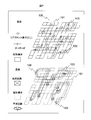
- FIG. 8 is a view showing another structure of an embodiment of a receiver antenna used in the frequency variable Fresnel area power transmission system according to the present invention, and a space in which a maximum of 10 ⁇ 10 minute rectangular conductors 101 can be arranged. In addition, it has a structure in which a plurality of inductors and capacitors are loaded as reactance elements.
- This antenna has a frequency of 950 MHz, a size of a small rectangular conductor of 5 mm ⁇ , and a distance between a transmitter and a receiver of 10 cm.
- a combination of connecting a high-Q capacitor or a high-Q inductor between minute rectangular conductors find the combination by brute force and find the appropriate element values of the capacitor and inductor by local optimization. It is the structure that was released.
- the reactance value realized by the inductor and the capacitor is between ⁇ j100 ohms and +100 johms at a working frequency of 950 MHz.
- an example of the structure of the antenna having the structure shown in FIG. 7 can be realized by a metal, a chip capacitor, a chip inductor, and a chip diode.
- FIG. 9 is a diagram showing the structure of another embodiment of the frequency variable Fresnel area power transmission system according to the present invention. 1 differs from the base station of the embodiment of FIG. 1 in that a plurality of receivers 20, receivers 40, and receivers 60 exist in the system for one transmitter 10, and the transmitter 10 has a second frequency.
- a variable carrier generation device 33, a second control circuit 34, a third frequency variable carrier generation device 53, a third control circuit 54, and a synthesis circuit 70 are newly provided.
- the control circuit is coupled in parallel to the demodulator 15 as in the embodiment of FIG. 1, and the outputs of the three frequency variable carrier generators are synthesized by the synthesis circuit 70 and supplied to the antenna 11 via the directional coupler 12. Is done.
- the frequency variable carrier wave generator 13, the frequency variable carrier wave generator 33, and the frequency variable carrier wave generator 53 have different carrier frequencies.
- power can be transmitted to a plurality of receivers with a single transmitter with high efficiency, so the number of transmitters per receiver can be reduced, resulting in a reduction in installation cost of the wireless power transmission system. Is effective.
- FIG. 10 shows another embodiment of the variable frequency Fresnel area power transmission system according to the present invention, the structure of the transmitter (FIG. 10A) of the frequency variable Fresnel area power transmission system of FIG. 10B).
- the control circuit 14 includes a temporary memory 116
- the control circuit 34 includes a temporary memory 336
- the control circuit 54 includes a temporary memory 556.
- the control circuit 14, the control circuit 34, and the control circuit 54 use the temporary memory 116, the temporary memory 336, and the temporary memory 556 to perform control similar to the procedure shown in the flowchart of FIG.
- the transmitter 10 needs to control wireless power transmission to a plurality of receivers, there is a difference in the control procedure of the entire transmitter. That is, in order for the transmitter 10 to automatically control the wireless power transmission efficiency for the receiver 20, the receiver 40, and the receiver 60, these three types of control are performed in series on the time axis.
- the transmitter 10 performs the procedure relating to the frequency control for the receiver 20, the receiver 40 and the receiver 60 in the period Tq.
- the processing is sequentially performed within the time Tc, and the result of the procedure relating to the frequency control is sequentially reflected on the transmission frequencies of the frequency variable carrier generator 13, the frequency variable carrier generator 33, and the frequency variable carrier generator 53.
- the carrier frequency transmitted by each receiver is maintained for a time of at least Tp. In this embodiment, since there are three receivers for one transmitter, Tp is equal to three times Tq.
- the effect of the embodiment of FIG. 2 can be added to the effect of the embodiment of FIG.
- FIG. 11 is a diagram showing the structure of the transmitter (FIG. 11A) of another embodiment of the frequency variable Fresnel region power transmission system according to the present invention and the time change (FIGS. 11B and 11C) of the frequency spectrum of the received reflected wave.
- . 10 differs from the base station of the embodiment of FIG. 10 in that the transmitter 10 includes a mixer 18, a filter 19, a changeover switch 81, and a central processing circuit 82, and the mixer 18 includes a directional coupler 12 and a demodulator 15.
- the mixer 18 is inserted between the filter 19 and the mixer 18 as a high-frequency signal obtained from the antenna 11 via the directional coupler 12 and subjected to the central processing as a reflected wave and a local oscillation signal modulated from the receiver 2.
- a part of the output of the frequency variable carrier generation device 13, the frequency variable carrier generation device 33 or the frequency variable carrier generation device 53 via the changeover switch 81 controlled by the circuit 82 is input, and the demodulator 15 is lower than the carrier wave.
- a low frequency signal having a frequency component is supplied as a sideband signal.
- the high frequency component signal generated by the mixer 18 can be excluded from the input of the demodulator 15 by using the filter 19 as a low-pass filter.
- 11B and 11C are diagrams showing the frequency spectrum of the high frequency input and low frequency output of the mixer.
- the demodulator 15 does not need to handle a high frequency signal, so that the circuit scale of the demodulator 15 can be reduced. Furthermore, since the frequency band of the signal supplied to the demodulator 15 is constant regardless of the wireless power transmission to the receiver 20, the receiver 40, and the receiver 60, the adaptive frequency band of the demodulator itself can be narrowed. There is an effect of simplifying the circuit configuration of the demodulator 15, especially the filter configuration. Further, since the analog / digital converter of the prior art can be used in such a low frequency band, the demodulating process of the demodulator 15 can be performed using the digital signal processing, and the circuit can be further downsized and demodulated. An improvement in accuracy can be realized.
- an electrostatic field an induction field, which are generated in space when performing power transmission by electromagnetic waves, Since all the radiation fields are used, it is possible to transmit power more efficiently than the conventional wireless system that focuses on a single field.
- the high-efficiency wireless power transmission is compensated for.
- the transmission frequency of the transmitter is made variable, and the antenna of the receiver
- the reactance element is loaded to increase the effect of canceling the change in the electrical environment of the space including the receiver against the frequency change.
Landscapes
- Engineering & Computer Science (AREA)
- Computer Networks & Wireless Communication (AREA)
- Power Engineering (AREA)
- Signal Processing (AREA)
- Near-Field Transmission Systems (AREA)
- Transmitters (AREA)
Abstract
Priority Applications (3)
| Application Number | Priority Date | Filing Date | Title |
|---|---|---|---|
| JP2010535551A JP5385298B2 (ja) | 2008-10-29 | 2008-10-29 | 周波数可変フレネル領域電力送信機および受信機、並びに電力伝送システム |
| US12/597,574 US8334619B2 (en) | 2008-10-29 | 2008-10-29 | Frequency variable power transmitter and receiver in Fresnel region and power transmitting system |
| PCT/JP2008/069625 WO2010050008A1 (fr) | 2008-10-29 | 2008-10-29 | Émetteur et récepteur de puissance électrique à région de fresnel variable en fréquence, et système de transmission de puissance électrique |
Applications Claiming Priority (1)
| Application Number | Priority Date | Filing Date | Title |
|---|---|---|---|
| PCT/JP2008/069625 WO2010050008A1 (fr) | 2008-10-29 | 2008-10-29 | Émetteur et récepteur de puissance électrique à région de fresnel variable en fréquence, et système de transmission de puissance électrique |
Publications (1)
| Publication Number | Publication Date |
|---|---|
| WO2010050008A1 true WO2010050008A1 (fr) | 2010-05-06 |
Family
ID=42128387
Family Applications (1)
| Application Number | Title | Priority Date | Filing Date |
|---|---|---|---|
| PCT/JP2008/069625 Ceased WO2010050008A1 (fr) | 2008-10-29 | 2008-10-29 | Émetteur et récepteur de puissance électrique à région de fresnel variable en fréquence, et système de transmission de puissance électrique |
Country Status (3)
| Country | Link |
|---|---|
| US (1) | US8334619B2 (fr) |
| JP (1) | JP5385298B2 (fr) |
| WO (1) | WO2010050008A1 (fr) |
Cited By (7)
| Publication number | Priority date | Publication date | Assignee | Title |
|---|---|---|---|---|
| JP2012080758A (ja) * | 2010-09-09 | 2012-04-19 | Semiconductor Energy Lab Co Ltd | 給電装置、給電装置を用いた無線給電システム、及び無線給電方法 |
| CN102545312A (zh) * | 2010-12-30 | 2012-07-04 | 电子部品研究院 | 利用磁场通信的多节点无线充电系统的充电方法 |
| CN102694422A (zh) * | 2011-03-22 | 2012-09-26 | 株式会社东芝 | 无线电力传送装置和无线电力传送系统 |
| JP2013102643A (ja) * | 2011-11-09 | 2013-05-23 | Tokai Rika Co Ltd | 非接触充電器 |
| JP2013534401A (ja) * | 2010-08-04 | 2013-09-02 | ジョンソン コントロールズ テクノロジー カンパニー | 自動車用ユニバーサルワイヤレス充電システム |
| CN103380561A (zh) * | 2010-09-30 | 2013-10-30 | 英特尔公司 | 无线功率传递设备及其方法 |
| JP5494838B2 (ja) * | 2011-01-26 | 2014-05-21 | 株式会社村田製作所 | 電力伝送システム |
Families Citing this family (14)
| Publication number | Priority date | Publication date | Assignee | Title |
|---|---|---|---|---|
| US8299652B2 (en) * | 2008-08-20 | 2012-10-30 | Intel Corporation | Wireless power transfer apparatus and method thereof |
| KR20110110525A (ko) * | 2010-04-01 | 2011-10-07 | 삼성전자주식회사 | 무선 전력 전송 장치 및 방법 |
| US20110309689A1 (en) * | 2010-06-17 | 2011-12-22 | Semiconductor Energy Laboratory Co., Ltd. | Electric power transmitting device, electric power receiving device, and power supply method using electric power transmitting and receiving devices |
| KR20120084659A (ko) | 2011-01-20 | 2012-07-30 | 가부시키가이샤 한도오따이 에네루기 켄큐쇼 | 급전 장치 및 비접촉 급전 시스템 |
| JP2013070580A (ja) * | 2011-09-26 | 2013-04-18 | Sony Corp | 受電装置、送電装置、非接触電力伝送システム及び非接触電力伝送方法 |
| US9071289B2 (en) * | 2012-04-23 | 2015-06-30 | Cambridge Silicon Radio Limited | Transceiver supporting multiple modulation schemes |
| KR101965252B1 (ko) | 2012-12-14 | 2019-04-04 | 삼성전자 주식회사 | 무선 전력 전송 장치, 무선 전력 수신 장치, 무선 전력 전송 시스템 및 무선 전력 전송 방법 |
| US10320234B2 (en) * | 2013-08-02 | 2019-06-11 | Integrated Device Technology, Inc. | Multimode wireless power receivers and related methods |
| US10958108B2 (en) * | 2017-05-03 | 2021-03-23 | Searete Llc | Wireless power transfer management |
| EP3635760B1 (fr) * | 2017-06-06 | 2023-09-13 | Reach Power, Inc. | Procédé pour une distribution d'énergie sans fil |
| US10452968B2 (en) * | 2017-06-14 | 2019-10-22 | Intermec, Inc. | Method to increase RFID tag sensitivity |
| US10430622B2 (en) | 2017-06-29 | 2019-10-01 | Intermec, Inc. | RFID tag with reconfigurable properties and/or reconfiguring capability |
| US10374470B1 (en) | 2018-08-31 | 2019-08-06 | At&T Intellectual Property I, L.P. | Wireless energy transfer in a far-field environment |
| US11411441B2 (en) * | 2019-09-20 | 2022-08-09 | Energous Corporation | Systems and methods of protecting wireless power receivers using multiple rectifiers and establishing in-band communications using multiple rectifiers |
Citations (2)
| Publication number | Priority date | Publication date | Assignee | Title |
|---|---|---|---|---|
| JP2008083679A (ja) * | 2006-08-31 | 2008-04-10 | Seiko Epson Corp | 表示装置および電子機器 |
| JP2008154198A (ja) * | 2006-11-21 | 2008-07-03 | Sony Corp | 通信システム並びに通信装置 |
Family Cites Families (14)
| Publication number | Priority date | Publication date | Assignee | Title |
|---|---|---|---|---|
| GB2135844B (en) * | 1983-02-21 | 1986-08-28 | Nippon Telegraph & Telephone | Oscillator with variable frequency and phase |
| US5519262A (en) * | 1992-11-17 | 1996-05-21 | Wood; Mark B. | Near field power coupling system |
| KR0133217B1 (ko) * | 1994-12-20 | 1998-04-21 | 구자홍 | 무선통신기기의 송수신 정합방법 및 그 장치 |
| DE60206309T2 (de) * | 2001-02-27 | 2006-06-29 | NGK Spark Plug Co., Ltd., Nagoya | Hochfrequenzleiterplatte und diese verwendendes Hochfrequenz-Antennenschaltmodul |
| US20050159187A1 (en) * | 2002-03-18 | 2005-07-21 | Greg Mendolia | Antenna system and method |
| JP2004023765A (ja) * | 2002-06-20 | 2004-01-22 | Sanyo Electric Co Ltd | 無線型データ伝送装置 |
| JP4060854B2 (ja) * | 2002-08-01 | 2008-03-12 | 株式会社日立製作所 | 移動体識別装置の質問器 |
| AU2002950621A0 (en) * | 2002-08-07 | 2002-09-12 | J I Peston Pty Ltd | Near-field antenna array with signal processing |
| US7911325B2 (en) * | 2003-03-06 | 2011-03-22 | Brother Kogyo Kabushiki Kaisha | Communication system, and endpoint device and interrogator |
| JP4298705B2 (ja) * | 2004-01-16 | 2009-07-22 | 三菱電機株式会社 | 電力供給装置及び電力供給方法 |
| WO2005112285A1 (fr) * | 2004-05-14 | 2005-11-24 | Brother Kogyo Kabushiki Kaisha | Dispositif de radiocommunication |
| JP4959956B2 (ja) * | 2005-06-07 | 2012-06-27 | 株式会社日立製作所 | アンテナ |
| JP2007122600A (ja) * | 2005-10-31 | 2007-05-17 | Fujitsu Ltd | 集積回路チップ及びrfidシステム |
| KR100802181B1 (ko) * | 2006-04-10 | 2008-02-12 | 한국전자통신연구원 | 프레넬 영역에서의 안테나 방사 패턴 측정 시스템 및 그방법 |
-
2008
- 2008-10-29 WO PCT/JP2008/069625 patent/WO2010050008A1/fr not_active Ceased
- 2008-10-29 US US12/597,574 patent/US8334619B2/en not_active Expired - Fee Related
- 2008-10-29 JP JP2010535551A patent/JP5385298B2/ja not_active Expired - Fee Related
Patent Citations (3)
| Publication number | Priority date | Publication date | Assignee | Title |
|---|---|---|---|---|
| JP2008083679A (ja) * | 2006-08-31 | 2008-04-10 | Seiko Epson Corp | 表示装置および電子機器 |
| JP2008154198A (ja) * | 2006-11-21 | 2008-07-03 | Sony Corp | 通信システム並びに通信装置 |
| JP2008154267A (ja) * | 2006-11-21 | 2008-07-03 | Sony Corp | 通信システム並びに通信装置 |
Cited By (16)
| Publication number | Priority date | Publication date | Assignee | Title |
|---|---|---|---|---|
| US9473209B2 (en) | 2008-08-20 | 2016-10-18 | Intel Corporation | Wireless power transfer apparatus and method thereof |
| JP2013534401A (ja) * | 2010-08-04 | 2013-09-02 | ジョンソン コントロールズ テクノロジー カンパニー | 自動車用ユニバーサルワイヤレス充電システム |
| US10044224B2 (en) | 2010-09-09 | 2018-08-07 | Semiconductor Energy Laboratory Co., Ltd. | Power feeding device, wireless power feeding system using the same and wireless power feeding method |
| US9391476B2 (en) | 2010-09-09 | 2016-07-12 | Semiconductor Energy Laboratory Co., Ltd. | Power feeding device, wireless power feeding system using the same and wireless power feeding method |
| JP2012080758A (ja) * | 2010-09-09 | 2012-04-19 | Semiconductor Energy Lab Co Ltd | 給電装置、給電装置を用いた無線給電システム、及び無線給電方法 |
| CN103380561A (zh) * | 2010-09-30 | 2013-10-30 | 英特尔公司 | 无线功率传递设备及其方法 |
| JP2013546291A (ja) * | 2010-09-30 | 2013-12-26 | インテル コーポレイション | 無線電力転送装置およびその方法 |
| US9030160B2 (en) * | 2010-12-30 | 2015-05-12 | Korea Electronics Technology Institute | Charging method of multi-node wireless charging system using magnetic field communication |
| US20120169293A1 (en) * | 2010-12-30 | 2012-07-05 | Korea Electronics Technology Institute | Charging method of multi-node wireless charging system using magnetic field communication |
| CN102545312A (zh) * | 2010-12-30 | 2012-07-04 | 电子部品研究院 | 利用磁场通信的多节点无线充电系统的充电方法 |
| JP5494838B2 (ja) * | 2011-01-26 | 2014-05-21 | 株式会社村田製作所 | 電力伝送システム |
| US8874031B2 (en) | 2011-03-22 | 2014-10-28 | Kabushiki Kaisha Toshiba | Radio power transmitting apparatus and radio power transmitting system |
| CN102694422B (zh) * | 2011-03-22 | 2015-01-28 | 株式会社东芝 | 无线电力传送装置和无线电力传送系统 |
| JP2012200085A (ja) * | 2011-03-22 | 2012-10-18 | Toshiba Corp | 無線電力伝送装置および無線電力伝送システム |
| CN102694422A (zh) * | 2011-03-22 | 2012-09-26 | 株式会社东芝 | 无线电力传送装置和无线电力传送系统 |
| JP2013102643A (ja) * | 2011-11-09 | 2013-05-23 | Tokai Rika Co Ltd | 非接触充電器 |
Also Published As
| Publication number | Publication date |
|---|---|
| JP5385298B2 (ja) | 2014-01-08 |
| US20110140537A1 (en) | 2011-06-16 |
| JPWO2010050008A1 (ja) | 2012-03-29 |
| US8334619B2 (en) | 2012-12-18 |
Similar Documents
| Publication | Publication Date | Title |
|---|---|---|
| JP5385298B2 (ja) | 周波数可変フレネル領域電力送信機および受信機、並びに電力伝送システム | |
| Costanzo et al. | Evolution of SWIPT for the IoT world: Near-and far-field solutions for simultaneous wireless information and power transfer | |
| US10027377B2 (en) | Wireless power supply apparatus | |
| Costanzo et al. | Smart solutions in smart spaces: Getting the most from far-field wireless power transfer | |
| JP4698702B2 (ja) | 電子機器 | |
| EP2338238B1 (fr) | Transmission de puissance sans fil simultanée et communication de champ proche | |
| JP5999693B2 (ja) | レクテナ | |
| CN106340976B (zh) | 无线送电装置及无线电力传输系统 | |
| US8618697B2 (en) | Wireless power system with selectable control channel protocols | |
| KR101896977B1 (ko) | 무선 전력 전송 시스템에서 통신 장치 및 통신 방법 | |
| Lim et al. | Feasibility study on ambient RF energy harvesting for wireless sensor network | |
| EP2720383A2 (fr) | Appareil et système de transmission de puissance sans fil | |
| JP2015505664A (ja) | 別々に整調可能な共振器を用いる無線電力伝送装置 | |
| CA2542930A1 (fr) | Procede et appareil pour alimentation sans fil | |
| US10224750B2 (en) | Wireless power transmission apparatus | |
| JP2010530098A (ja) | タッグデバイス、リーダーデバイス、rfidシステム | |
| US20180205268A1 (en) | Method for operating wireless power transmission device | |
| US20160371515A1 (en) | Apparatus and method for transmitting and receiving rf signal using beamforming | |
| KR101925842B1 (ko) | 무선 전력 전송 시스템을 위한 자가 공진 장치 | |
| US20210328459A1 (en) | Energy harvesting antenna for harvesting energy from frequency modulation radio signals | |
| KR20190074767A (ko) | 무선통신코일을 구비한 무선충전장치 | |
| KR20170005589A (ko) | 무선 전력 송신 장치 및 무선 전력 송신 시스템 | |
| KR20200088584A (ko) | 데이터와 전력을 동시에 전송하는 무선 송·수신 시스템 | |
| KR20190041754A (ko) | 무선 전력 수신 방법 및 장치 | |
| KR20150066070A (ko) | 무선전력 전송 시스템 및 방법 |
Legal Events
| Date | Code | Title | Description |
|---|---|---|---|
| WWE | Wipo information: entry into national phase |
Ref document number: 12597574 Country of ref document: US |
|
| 121 | Ep: the epo has been informed by wipo that ep was designated in this application |
Ref document number: 08877720 Country of ref document: EP Kind code of ref document: A1 |
|
| WWE | Wipo information: entry into national phase |
Ref document number: 2010535551 Country of ref document: JP |
|
| NENP | Non-entry into the national phase |
Ref country code: DE |
|
| 122 | Ep: pct application non-entry in european phase |
Ref document number: 08877720 Country of ref document: EP Kind code of ref document: A1 |