WO2010050146A1 - Capteur de gaz - Google Patents
Capteur de gaz Download PDFInfo
- Publication number
- WO2010050146A1 WO2010050146A1 PCT/JP2009/005491 JP2009005491W WO2010050146A1 WO 2010050146 A1 WO2010050146 A1 WO 2010050146A1 JP 2009005491 W JP2009005491 W JP 2009005491W WO 2010050146 A1 WO2010050146 A1 WO 2010050146A1
- Authority
- WO
- WIPO (PCT)
- Prior art keywords
- gas
- protector
- detection
- gas sensor
- detection element
- Prior art date
- Legal status (The legal status is an assumption and is not a legal conclusion. Google has not performed a legal analysis and makes no representation as to the accuracy of the status listed.)
- Ceased
Links
Images

Classifications
-
- G—PHYSICS
- G01—MEASURING; TESTING
- G01N—INVESTIGATING OR ANALYSING MATERIALS BY DETERMINING THEIR CHEMICAL OR PHYSICAL PROPERTIES
- G01N27/00—Investigating or analysing materials by the use of electric, electrochemical, or magnetic means
- G01N27/26—Investigating or analysing materials by the use of electric, electrochemical, or magnetic means by investigating electrochemical variables; by using electrolysis or electrophoresis
- G01N27/403—Cells and electrode assemblies
- G01N27/406—Cells and probes with solid electrolytes
- G01N27/407—Cells and probes with solid electrolytes for investigating or analysing gases
- G01N27/4077—Means for protecting the electrolyte or the electrodes
Definitions
- the present invention relates to an intake gas passage through which intake gas is sucked into the internal combustion engine from the outside, and an intake gas recirculation gas through which intake recirculation gas for recirculating exhaust gas flows to reduce exhaust emissions of the internal combustion engine.
- the present invention relates to a gas sensor disposed in an intake passage such as a passage.
- a gas sensor attached to an intake passage such as an intake gas passage or an intake recirculation gas passage
- electromotive forces having different sizes are generated or the resistance value is changed according to the concentration of, for example, NOx (nitrogen oxide) or oxygen.
- a gas sensor provided with a detection element is known (see, for example, Patent Document 3). While this gas sensor is exposed to high-temperature measurement gas such as intake gas and intake recirculation gas, the moisture contained in the gas adheres (water), so the detection element may be subjected to thermal shock to cause cracks or cracks. There is. Therefore, a protector that covers the detection element is attached to the gas sensor to protect the detection element from water.
- soot carbon
- this protector for example, it is provided so as to surround the periphery of the detection portion of the detection element, and protects the detection element from water or dirt.
- a gas introduction hole is provided in the protector.
- JP 2005-61420 A Japanese Patent Application Publication No. 2006-2761 Japanese Patent Application Laid-Open No. 10-293113
- the soot may block the gas introduction hole of the protector (hereinafter, also referred to as clogging). As a result, the measured gas is less likely to be exposed to the detection portion of the detection element, and the detection accuracy of the detection element is reduced.
- the gas introduction hole is made relatively large in consideration of clogging of the protector, the detection element may be flooded or wrinkles may be attached to the detection element. As a result, the detection element may be cracked or broken, or the detection accuracy may be lowered.
- the present invention has been made to solve the above-mentioned problems, and it is possible to prevent clogging of the gas introduction hole of the protector and to cause the detection element to be covered with water or to attach a wrinkle to the detection element. It is an object of the present invention to provide a gas sensor provided with a protector that suppresses
- the gas sensor of Configuration 1 extends in the axial direction, has a detection unit for detecting a specific gas component in the gas to be measured on its tip side, and heats the detection unit A plate-shaped detection element in which the heaters are stacked, a cylindrical metal shell surrounding the circumference of the detection element in the radial direction while causing the detection section to project from the tip of the detection element, and the detection section of the detection element inside And a protector fixed to the metal shell while housing the gas sensor, the gas sensor being disposed in an intake passage of an internal combustion engine,
- the protector has an inner protector disposed with a gap between the detection unit and the outer protector, and an outer protector disposed with a gap between the inner protector and the inner protector.
- the outer protector has an inner gas introduction portion which can be introduced inside, and an inner side wall portion which is disposed radially outside the detection portion, and the outer protector is an outer side which can introduce the measurement gas into the outer protector.
- a gas sensor having a gas introduction portion and an outer wall portion disposed radially outward of the inner wall portion, wherein at least a portion of the inner wall portion has a clearance of 1.35 mm or less with respect to the detection portion.
- the temperature of the inner protector is characterized by being higher than the temperature of the outer protector.
- the gas sensor of the structure 2 is characterized by the clearance with the said detection part of the whole said inner side wall part becoming 1.35 mm or less.
- the gas sensor according to Configuration 3 is characterized in that, in addition to the configuration 1 or 2, the entire outer wall portion has a clearance of 1 mm or more with respect to the inner wall portion.
- the gas sensor according to Configuration 4 is characterized in that, in addition to any one of the configurations 1 to 3, the outer gas introduction portion and the inner gas introduction portion do not overlap.
- the gas sensor of configuration 5 is characterized in that the outer gas introduction portion is disposed downstream of the intake passage.
- the outer protector in addition to the fifth aspect, has an outer bottom connected to the tip end side of the outer wall, and the outer bottom has the upstream side of the intake passage. It has a gas lead-out part which can lead out said measured gas from an outside protector.
- the inner protector has an inner bottom portion connected to the tip side of the inner side wall portion and covering at least a part of the tip surface of the detection element. It is characterized by
- the gas sensor according to the configuration 8 is characterized in that the inner gas introduction portion is disposed on the upstream side of the intake passage.
- the gas sensor according to the configuration 9 is characterized in that the inner gas introduction portion is formed to expose at least one side surface of the detection element.
- the inner gas introduction portion is formed to expose at least a part of the gas communication portion for exposing the measurement gas to the detection portion. It is characterized by
- the gas sensor according to the configuration 11 is characterized in that the heater is disposed closer to the inner side wall portion than an axis of the detection element.
- the gas sensor of the invention according to Configuration 1 comprises a protector having an inner protector and an outer protector.
- the temperature of the inner protector is preferably 280 ° C. or higher.
- the moisture adhering to the inner side wall can be positively evaporated, or the wrinkles can be positively removed from the inner side wall.
- the temperature of the inner protector is made higher than the temperature of the outer protector.
- the outer protector is less susceptible to the heat from the heater, and the temperature of the inner protector can be efficiently raised to 280 ° C. or higher, so that the water adhering to the inner side wall is evaporated or the adhesion is made to the inner side wall Can be baked or peeled off from the inner wall. As a result, it is possible to suppress the adhesion of moisture or soot to the detection element.
- the inner protector (inner wall portion) and the detection portion are disposed with a gap, and at least a portion of the inner wall portion is disposed such that the clearance with the detection portion is 1.35 mm or less. ing.
- the inner protector receives heat from the heater stacked on the detection element to reach a temperature of 280 ° C. or higher and a temperature higher than the temperature of the outer protector.
- the inner protector comes in contact with the detection unit, the heat of the heater is excessively transmitted to the inner protector, and more heater power is required to maintain the detection unit at a predetermined temperature.
- the clearance between the inner side wall portion and the detection portion exceeds 1.35 mm, the heat from the heater is less likely to be received by the inner protector, and it becomes difficult to raise the temperature of the inner protector.
- the temperature of the inner protector is higher than the temperature of the outer protector
- the gas sensor is attached to the intake passage and the gas sensor detects a specific gas component in the gas to be measured. Comparing the temperature of any position of the protector with the temperature of any position of the outer protector, it is sufficient if the temperature of the inner protector is high, and at normal temperature, the temperature of the inner protector and the temperature of the outer protector are the same It may be.
- the temperature of the outer protector is lower than the temperature of the inner protector and is 280 ° C. or higher, the water adhering to the outer wall can be positively evaporated or the sputum can be positively incinerated or removed. However, it may be 280 ° C. or less.
- the inner side wall portion is arranged so that the clearance with the detection portion is 1.35 mm or less” means that the clearance between the inner side wall portion and the detection portion is 1.35 mm or less It means that one or more locations should be formed.
- the material of the inner protector may be a material having a higher thermal conductivity than the material of the outer protector. This allows the temperature of the inner protector to be effectively higher than the temperature of the outer protector when the gas sensor is used. Further, the temperature of the inner protector and the temperature of the outer protector can be measured by a thermocouple or a radiation thermometer.
- the entire inner side wall portion has a clearance of 1.35 mm or less with respect to the detection portion. Therefore, the heat from the heater can be reliably received by the inner protector.
- the entire outer wall portion has a clearance of 1 mm or more with respect to the inner wall portion.
- the outer gas introduction portion and the inner gas introduction portion do not overlap.
- the gas to be measured which has passed through the outer gas introduction portion inevitably comes into contact with the inner side wall portion without directly passing through the inner gas introduction portion, and moisture and soot adhere to the inner side wall portion of the inner protector.
- the outer gas introducing portion and the inner gas introducing portion do not overlap means that the inner gas introducing portion passes the axis and when the outer gas introducing portion is viewed in the vertical direction from a virtual line perpendicular to the axial direction. It points to an invisible thing.
- the inner gas introduction portion and the outer gas introduction portion may be disposed so as to be offset in the axial direction, or are disposed offset in the circumferential direction of the protector. It may be
- the outer gas introduction portion be disposed on the downstream side of the intake passage.
- the gas to be measured is introduced from the downstream side of the intake passage to the outer protector.
- water and soot contained in the gas to be measured flow from upstream to downstream according to the gas to be measured flowing from upstream to downstream in the intake passage, and it is difficult to flow from downstream to upstream in the intake passage. It becomes difficult to be introduced inside.
- the outer gas introduction portion is disposed downstream of the intake passage means that the gas sensor is disposed in the intake passage and the outer gas introduction portion is visually observed when the gas sensor is viewed from the downstream side of the intake passage. Point out what you can do.
- the outer protector has an outer bottom connected to the tip side of the outer wall, and the measured gas is supplied from the outer protector upstream of the intake passage at the outer bottom.
- the measured gas flows from the downstream side to the upstream side of the intake path in the outer protector, so that the measured gas can be efficiently replaced in the outer protector, and the measured gas of the detection portion Detection accuracy is improved.
- the inner protector has an inner bottom portion connected to the tip side of the inner side wall portion and covering at least a part of the tip surface of the detection element.
- the inner gas introducing portion be disposed on the upstream side of the intake passage.
- the distance from the outer gas introduction portion disposed downstream of the intake passage is distanced, and the measured gas having passed through the outer gas introduction portion strikes the inner side wall longer before reaching the inner gas introduction portion.
- more moisture and wrinkles can be attached to the inner side wall portion of the inner protector.
- the phrase "the inner gas introduction portion is disposed upstream of the intake passage” means that the gas sensor is disposed in the intake passage and the outer wall is visible when the gas sensor is viewed from the upstream side of the intake passage. It refers to being disposed on the opposing inner side wall portion.
- the inner gas introduction portion is preferably formed to expose at least one side surface of the detection element.
- the inner gas introduction portion is preferably formed to expose at least a part of the gas communication portion for exposing the measurement gas to the detection portion.
- the heater is preferably disposed closer to the inner side wall portion than the axis of the detection element.
- the heater is disposed closer to the inner wall than the axis of the detection element” means that the distance between the inner wall and the heater is smaller than the distance between the inner part and the axis of the detection element. .
- FIG. 2 is a cross-sectional view of the gas sensor 1 shown in FIG. It is a perspective view of the outer side protector 110 of this embodiment. It is a perspective view of inner side protector 120 of this embodiment. It is a figure which attached gas sensor 1 of this embodiment to intake passage 2. As shown in FIG.
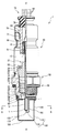
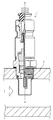
- FIG. 1 is a partial cross-sectional view of the gas sensor 1.
- the axis O direction of the gas sensor 1 (indicated by a dot-and-dash line) is shown as the vertical direction, and the detection unit 11 side of the detection element 10 held inside is the tip end side of the gas sensor 1, the rear end 12 The side will be described as the rear end side of the gas sensor 1.
- the gas sensor 1 shown in FIG. 1 is attached to an intake passage 2 (see FIG. 5) of an internal combustion engine, and a detection unit 11 of a detection element 10 held therein is in intake gas or intake recirculation gas flowing through the intake passage 2. It is a so-called full-range air-fuel ratio sensor that is exposed to detect the air-fuel ratio from the concentration of oxygen in the intake gas and the intake air recirculation gas.
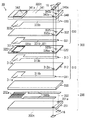
- the detection element 10 has a strip shape extending in the direction of the axis O, and an element body 300 (see FIG. 2) that detects the oxygen concentration, and a heater 200 (see FIG. 2) that heats the element body for early activation. Are bonded together and integrated as a substantially prismatic laminate. Then, in order to protect the detection electrode from poisoning by the intake gas and the intake recirculation gas, a protective layer 15 is formed on the detection portion 11 formed on the tip side of the detection element 10 so as to wrap the outer peripheral surface thereof. . On the other hand, at the rear end 12 on the rear end side of the detection element 10, five electrode pads 16 (one of which is shown in FIG. 1) for taking out the electrode from the gas detection body or the heater body. It is formed.
- FIG. 2 is an exploded perspective view of the detection element 10.
- the protective layer 15 is not shown in FIG.
- the detection element 10 is a stack of an element main body 300 and a heater 200
- the element main body 300 is a stack of an oxygen concentration detection cell 310 and an oxygen pump cell 330. .
- the heater 200 includes a first base 201 and a second base 203 mainly made of alumina, and a heat generating body 202 mainly made of platinum, which is sandwiched between the first base 201 and the second base 203.
- the heat generating body 202 has a heat generating portion 202 a located on the tip end side, and a pair of heater lead portions 202 b extending from the heat generating portion 202 a along the longitudinal direction of the first base 201.
- the terminal of the heater lead portion 202 b is electrically connected to the electrode pad 16 through the heater side through hole 201 a provided in the first base 201.
- the oxygen concentration detection cell 310 is formed of a first solid electrolyte body 312 and first and second electrodes 311 and 313 formed on both sides of the first solid electrolyte body 312.
- the first electrode 311 is formed of a first electrode portion 311 a and a first lead portion 311 b extending along the longitudinal direction of the first solid electrolyte body 312 from the first electrode portion 311 a.
- the second electrode 313 is formed of a second electrode portion 313a and a second lead portion 313b extending along the longitudinal direction of the first solid electrolyte body 312 from the second electrode portion 313a.
- the terminal of the first lead portion 311 b is provided in a first through hole 312 a provided in the first solid electrolyte body 312, a second through hole 320 a provided in the insulating layer 320 described later, and a second solid electrolyte body 332. It is electrically connected to the electrode pad 16 through the fourth through hole 332 a and the sixth through hole 340 a provided in the electrode protection layer 340.
- the end of the second lead portion 313 b is a third through hole 320 b provided in the insulating layer 320, a fifth through hole 332 b provided in the second solid electrolyte body 332, and a seventh through hole 340 b provided in the electrode protection layer 340. And electrically connected to the electrode pad 16.
- the oxygen pump cell 330 is formed of a second solid electrolyte body 332 and third and fourth electrodes 331 and 333 formed on both sides of the second solid electrolyte body 332.
- the third electrode 331 is formed of a third electrode portion 331 a and a third lead portion 331 b extending along the longitudinal direction of the second solid electrolyte body 332 from the third electrode portion 331 a.
- the fourth electrode 333 is formed of a fourth electrode portion 333a and a fourth lead portion 333b extending from the fourth electrode portion 333a in the longitudinal direction of the second solid electrolyte body 332.
- the terminal of the third lead portion 331 b is electrically connected to the electrode pad 16 through the fifth through hole 332 b provided in the second solid electrolyte body 332 and the seventh through hole 340 b provided in the electrode protection layer 340.
- the terminal of the fourth lead portion 333 b is electrically connected to the electrode pad 16 through an eighth through hole 340 c provided in the electrode protection layer 340.
- the second lead portion 313 b and the third lead portion 331 b are at the same potential through the third through hole 320 b.
- the first solid electrolyte body 312 and the second solid electrolyte body 332 are composed of a partially stabilized zirconia sintered body obtained by adding yttria (Y 2 O 3) or calcia (CaO) as a stabilizer to zirconia (ZrO 2) There is.
- the heating element 202, the first electrode 311, the second electrode 313, the third electrode 331, the fourth electrode 333 and the electrode pad 16 can be formed of a platinum group element.
- Pt, Rh, Pd etc. can be mentioned as a suitable platinum group element which forms these, These can also be used individually by 1 type, and can also use 2 or more types together.
- the heat generating body 202, the first electrode 311, the second electrode 313, the third electrode 331, the fourth electrode 333 and the electrode pad 16 contain a ceramic component in addition to the main platinum group element.
- An insulating layer 320 is formed between the oxygen concentration detection cell 310 and the oxygen pump cell 330.
- the insulating layer 320 includes an insulating portion 321 and a diffusion rate controlling portion 322.
- a gas detection chamber 320c is formed at a position corresponding to the second electrode portion 313a and the third electrode portion 331a.
- the gas detection chamber 320c is in communication with the outside in the width direction of the insulating layer 320, and in the communication portion, diffusion-limited to realize gas diffusion between the outside and the gas detection chamber 320c under predetermined rate-limiting conditions
- a part 322 is arranged.
- the diffusion control unit 322 corresponds to the gas communication unit in the claims.
- the insulating portion 321 is not particularly limited as long as it is a ceramic sintered body having an insulating property, and examples thereof include oxide ceramics such as alumina and mullite.
- the diffusion control part 322 is a porous body made of alumina. The diffusion control unit 322 performs rate control when the detection gas flows into the gas detection chamber 320 c.
- an electrode protection layer 340 is formed on the surface of the second solid electrolyte body 332 so as to sandwich the fourth electrode 333.
- a porous electrode protection portion 342 sandwiching the fourth electrode portion 333a is inserted into a through hole 341a formed in the reinforcing portion 341 sandwiching the fourth lead portion 333b.
- a metal cup 20 having a bottomed cylindrical metal shape inserts the detection element 10 into itself at a slightly tip end side from the center of the body 13 of the detection element 10, and the detection portion 11 Is disposed so as to project from the opening 25 at the bottom of the cylinder.
- the metal cup 20 is a member for holding the detection element 10 in the metal shell 50, and the tip peripheral edge portion 23 of the edge portion of the cylinder bottom is formed in a tapered shape over the outer peripheral surface.
- a ceramic ring 21 made of alumina and a talc ring 22 obtained by compressing and solidifying talc powder are accommodated in a state in which they are inserted through the detection element 10.
- the talc ring 22 is crushed in the metal cup 20 and filled with details so that the detection element 10 is positioned and held in the metal cup 20.
- the detection element 10 integrated with the metal cup 20 is held so as to be surrounded by a cylindrical metal shell 50 around the periphery thereof.
- the metal shell 50 is for fixing the gas sensor 1 to the intake passage 2 of a car and is made of low carbon steel such as SUS 430, and has an external thread 51 for attachment to the exhaust pipe or vent pipe on the outer peripheral tip side. It is done.
- a distal end engaging portion 56 with which a protector 100 described later is engaged is formed on the distal end side of the male screw portion 51.
- a tool engaging portion 52 engaged with a mounting tool is formed at the center of the outer periphery of the metal shell 50, and between the tip end surface of the tool engaging portion 52 and the rear end of the male screw portion 51.
- a gasket 55 is fitted in order to prevent outgassing when attached to the intake passage 2. Furthermore, the detection element 10 is crimped and held in the metal shell 50 at the rear end side of the tool engagement portion 52, and at the rear end side, the rear end engagement portion 57 with which the outer cylinder 30 described later is engaged. A caulking portion 53 is formed.
- a stepped portion 54 is formed in the vicinity of the male screw portion 51 on the inner periphery of the metal shell 50.
- the leading edge portion 23 of the metal cup 20 holding the detection element 10 is engaged with the step 54.
- a talc ring 26 is loaded on the inner circumference of the metal shell 50 from the rear end side of the metal cup 20 in a state in which the talc is inserted through the detection element 10.
- a cylindrical sleeve 27 is fitted into the metal shell 50 so as to press the talc ring 26 from the rear end side.
- a stepped shoulder 28 is formed on the outer periphery on the rear end side of the sleeve 27, and an annular caulking packing 29 is disposed on the shoulder 28.
- the caulking portion 53 of the metal shell 50 is caulked so as to press the shoulder 28 of the sleeve 27 toward the tip end side via the caulking packing 29.
- the talc ring 26 pressed against the sleeve 27 is crushed in the metal shell 50 and filled in detail, and by means of this talc ring 26 and the talc ring 22 preloaded in the metal cup 20, the metal cup 20 and the detection
- the element 10 is positioned and held in the metal shell 50.
- the airtightness in the metal shell 50 is maintained by the caulking packing 29 interposed between the caulking portion 53 and the shoulder 28 of the sleeve 27 to prevent the outflow of the combustion gas.
- the detection element 10 has a rear end 12 projecting rearward than the rear end (swaged portion 53) of the metal shell 50, and the rear end 12 is covered with a cylindrical separator 60 made of insulating ceramic. It is done.
- the separator 60 has five connection terminals 61 (one of which is shown in FIG. 1) electrically connected to the five electrode pads 16 formed at the rear end 12 of the detection element 10.
- the connection portions of the connection terminals 61 and the five lead wires 65 (three of which are illustrated in FIG. 1) drawn out of the gas sensor 1 are accommodated. I am protected.
- a cylindrical outer cylinder 30 is disposed to surround the periphery of the rear end portion 12 of the detection element 10 in which the separator 60 is fitted.
- the outer cylinder 30 is made of stainless steel (e.g., SUS 304), and the open end 31 on the front end side of the outer cylinder 30 is engaged with the outer periphery of the rear end engaging portion 57 of the metal shell 50.
- the opening end 31 is caulked from the outer peripheral side, and laser welding is applied around the outer periphery to be joined to the rear end engaging portion 57, and the outer cylinder 30 and the metal shell 50 are integrally fixed. ing.
- a cylindrical metal holding fitting 70 is disposed in the gap between the outer cylinder 30 and the separator 60.
- the holding metal fitting 70 has a support portion 71 formed by bending its rear end inward, and supports a collar portion 62 provided in the shape of a hook on the rear end side outer periphery of the separator 60 inserted into the inner portion. And the separator 60 is supported. In this state, the outer peripheral surface of the outer cylinder 30 at the portion where the holding bracket 70 is disposed is crimped, and the holding bracket 70 supporting the separator 60 is fixed to the outer cylinder 30.
- a grommet 75 made of fluorine-based rubber is fitted in the opening on the rear end side of the outer cylinder 30.
- the grommet 75 has five insertion holes 76 (one of which is shown in FIG. 1), and the five lead wires 65 drawn from the separator 60 are airtightly inserted through the insertion holes 76. ing. In this state, the grommet 75 is crimped from the outer periphery of the outer cylinder 30 while pressing the separator 60 to the front end side, and is fixed to the rear end of the outer cylinder 30.
- the protector 100 which is the main part of the present invention will be described.
- the protector 100 is fixed to the front end engaging portion 56 of the metal shell 50 so as to surround the detection portion 11 of the detection element 10.
- the protector 100 prevents adhesion of soot and water in the intake gas and the intake recirculation gas to the detection element 10.
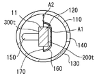
- the structure of the protector 100 shown in FIG. 1 will be described with reference to FIGS. 3 to 5 as well.
- 3 is a cross-sectional view taken along the line AA shown in FIG. 1
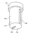
- FIG. 4 is a perspective view of the outer protector 110
- FIG. 5 is a perspective view of the inner protector 120.
- the protector 100 includes an inner protector 120 spaced from the detection portion 11 of the detection element 10 and an outer protector 110 spaced from the inner protector 120. It has a double structure configured.
- the outer protector 110 is made of stainless steel such as SUS 304, and has an outer proximal end 131 whose outer diameter is larger than that of the outer wall 130 and the outer wall 130, as shown in FIGS.
- the outer base end portion 131 is engaged with the tip end diameter mating portion 56 of the metal shell 50 and is welded to the metal shell 50 by laser welding all around.
- the outer wall portion 130 is cylindrically provided on the distal end side of the outer base end portion 131, and one slit-shaped outer gas introducing portion 140 extending in the axial direction is provided on the outer peripheral surface. Intake gas and intake recirculation gas are introduced into the outer protector 110 from the outside through the outer gas introduction portion 140.
- an outer bottom portion 132 is provided on the tip end side of the outer wall portion 130, and the outer bottom portion 132 is provided with a lead-out portion 150 from which the intake gas and the intake recirculation gas are led. As described later, when the gas sensor 1 is disposed in the intake passage 2, the outer gas introducing portion 140 of the outer protector 110 is disposed downstream of the intake passage 2.
- the inner protector 120 is formed of stainless steel such as SUS 304, and as shown in FIGS. 1 and 5, the inner proximal end portion 161 whose outer diameter is larger than that of the inner side wall portion 160 and the inner side wall portion 160 Have.
- the inner base end portion 161 is engaged with the tip end diameter fitting portion 56 of the metal shell 50, and is welded with the outer base end portion 131 all around with the metal shell 50 by laser welding.
- the inner proximal end portion 161 is also welded to the distal end surface of the distal end engaging portion 56 of the metal shell.
- the inner side wall portion 160 is provided in a semicircular arc shape on the distal end side of the inner base end portion 161, and covers the heater 200 side of the detection portion 11 of the detection element 10.
- An inner gas introducing portion 170 is provided at a radial end of the inner side wall portion 160, and in the present embodiment, the element main body 300 side of the detecting portion 11 protrudes from the inner gas introducing portion 170, and the outer protector 110 Exposed to the interior space of Furthermore, an inner bottom portion 162 is provided on the tip side of the inner side wall portion 160 so as to cover the tip of the detection portion 11 of the detection element 10. As described later, when the gas sensor 1 is disposed in the intake passage 2, the inner gas introduction portion 170 of the inner protector 110 is disposed on the upstream side of the intake passage 2.
- the gas sensor 1 is disposed in the intake passage 2 as shown in FIG. Gas flows from the upstream toward the downstream in the intake passage 2 (in the direction of the arrow in FIG. 6). At this time, the outer gas introducing portion 140 of the outer protector 110 is disposed on the downstream side of the intake passage 2. Thus, the gas is introduced from the downstream side of the intake passage 2 to the outer protector 110.
- the inner protector can be provided even if the outer gas introducing portion 140 is relatively enlarged in consideration of clogging of the outer gas introducing portion 140.
- the moisture and the soot adhere to the inner side wall portion 160 of 120, and the deposition of the moisture and the soot to the detection element 10 can be suppressed. As a result, it is possible to suppress the occurrence of a crack or a crack in the detection element 10 or to suppress the decrease in detection accuracy.
- this inner protector 120 arrange
- the temperature of the inner protector 120 is higher than the temperature of the outer protector 110. Specifically, the temperature of the inner protector 120 is 350 ° C., and the temperature of the outer protector 110 is 120 ° C.
- the water adhering to the inner side wall portion 160 can be evaporated, the crucible adhering to the inner side wall portion 160 can be baked, and the inner side wall portion 160 can be peeled off.
- the inner side wall portion 160 receives heat from the heater 200 for heating the detection portion 11. As a result, there is no need to separately provide heating means for heating the inner protector 110, and the configuration becomes easy.
- the relationship between the clearance A1 between the inner sidewall portion 160 of the inner protector 120 and the detection portion 11 and the temperature of the inner protector 120 is as shown in Table 1 below.
- This Table 1 arranges the detection part 11 in the inside protector 120 (the outside protector 110 is not arrange
- the clearance between the entire outer wall 130 and the inner wall 160 is 2.8 mm.
- the clearance A2 between the outer side wall portion 130 and the inner side wall portion 160 is 1 mm or more. Clogging does not occur in the gap between the inner wall portion 160 and the outer wall portion 130, and the gas to be measured is sufficiently exposed to the detection portion 11 of the detection element 10, and the detection accuracy of the detection element 10 is lowered. Can be suppressed.
- the outer protector 110 and the inner protector 120 are fixed to the distal end diameter fitting portion 56 of the metal shell 50, as shown in FIGS. 1 and 2, the outer gas introducing portion 140 and the inner gas introducing portion 170 do not overlap. Arranged as. As a result, the gas that has passed through the outer gas introducing portion 140 inevitably comes into contact with the inner side wall portion 160 without directly passing through the inner gas introducing portion 170, and moisture and dirt are generated in the inner side wall portion 160 of the inner protector 120. Is easy to attach. Therefore, it is possible to efficiently suppress the occurrence of a crack or a crack in the detection element 10 or to suppress a decrease in detection accuracy.
- the outer gas introduction portion 140 of the outer protector 110 is disposed downstream of the intake passage 2.
- the gas is introduced from the downstream side of the intake passage 2 to the outer protector 110.
- moisture and soot contained in the gas flow from the upstream to the downstream according to the gas flowing from the upstream to the downstream in the intake passage 2, and it is difficult to flow from the downstream to the upstream in the intake passage 2 It is difficult to introduce Therefore, moisture and wrinkles introduced into the outer protector 110 from the outside can be reduced.
- the outer bottom portion 132 is provided with a gas lead-out portion 150 capable of leading the measured gas from the outer protector 110 on the upstream side of the intake passage 2.
- the measurement gas can be efficiently replaced in the outer protector 110 by the measurement gas flowing from the downstream side to the upstream side of the intake path 2 in the outer protector 110, and the detection unit 11 detects the measurement gas. Accuracy is improved.
- the inner protector 120 has an inner bottom portion 162 covering the distal end surface of the detection element 10.
- the inner gas introducing portion 170 of the inner protector 110 is disposed on the upstream side of the intake passage 2. As a result, the distance between the inner gas introducing portion 170 and the outer gas introducing portion 140 disposed on the downstream side of the intake passage 2 is increased, and the gas passing through the outer gas introducing portion 140 reaches the inner gas introducing portion 170.
- the inner wall portion 160 is longer than the inner wall portion 160, and more moisture and wrinkles can be attached to the inner wall portion 160 of the inner protector 120.
- the inner gas introducing portion 170 is formed to expose the side surface 300 t of the element main body 300. As a result, more gas to be measured is introduced into the inner protector 100, the gas to be measured is easily exposed to the detection unit 11, and the detection accuracy of the detection unit 11 for the gas to be measured is improved.
- the inner gas introduction portion 170 is formed to expose the diffusion control portion 322. As a result, more measurement gas introduced into the outer protector 110 is exposed to the detection unit 11, and the detection accuracy of the detection unit 11 for the measurement gas is further improved.
- the heater 200 is disposed closer to the inner side wall portion 160 than the axis of the detection element 10. That is, the side surface 200 t forming the detection element 10 of the heater 200 is opposed to the inner side wall portion 160. Thereby, the heat from the heater 200 can be efficiently transmitted to the inner protector 120.
- the present invention is not limited to the above embodiments, and various modifications are possible.
- the outer gas introducing portion 140 and the inner gas introducing portion 170 are provided on the outer wall portion 130 and the inner side wall portion 160 respectively one by one, but the present invention is not limited thereto. A plurality of units may be provided.
- the outer side gas introducing part 140 was formed in the slit shape extended in an axial direction, it is not restricted to this, A circular shape may be sufficient.
- the inner side wall portion 160 is formed in a semicircular arc shape, but the present invention is not limited thereto. Even if it is formed in a cylindrical shape covering most of the detection element 10 like the outer wall portion 130 Good.
- the outer gas introducing portion 140 and the inner gas introducing portion 170 are respectively formed on the downstream side and the upstream side of the intake passage, but the present invention is not limited thereto.
- the gas introducing unit may be provided downstream.
- the full-range air-fuel ratio sensor has been described as an example in the present embodiment, the present invention can be similarly applied to a protector attached to an oxygen sensor, an NOx sensor, an HC sensor, a temperature sensor or the like.
Landscapes
- Chemical & Material Sciences (AREA)
- Life Sciences & Earth Sciences (AREA)
- Health & Medical Sciences (AREA)
- Physics & Mathematics (AREA)
- Chemical Kinetics & Catalysis (AREA)
- Electrochemistry (AREA)
- Molecular Biology (AREA)
- Analytical Chemistry (AREA)
- Biochemistry (AREA)
- General Health & Medical Sciences (AREA)
- General Physics & Mathematics (AREA)
- Immunology (AREA)
- Pathology (AREA)
- Measuring Oxygen Concentration In Cells (AREA)
Abstract
L'invention porte sur un capteur de gaz, équipé de protecteurs, capable de réduire l'obstruction d'entrées de gaz dans les protecteurs et de réduire l'exposition d'un élément de détection à l'eau et à la suie adhérant à l'élément de détection. Le capteur de gaz (1) est pourvu d’un protecteur intérieur (120) et d’un protecteur extérieur (110). Le protecteur intérieur (120) est pourvu d’une partie de paroi intérieure (160) ayant une partie d'entrée de gaz intérieure (170) capable d'introduire un gaz devant être mesuré à l'intérieur du protecteur intérieur (120). Le protecteur extérieur (110) est pourvu d’une partie de paroi extérieure (130) ayant une partie d'entrée de gaz extérieure (140) capable d'introduire le gaz devant être mesuré dans le protecteur extérieur (110). Au moins une partie de la partie de paroi intérieure (160) a un espacement égal ou inférieur à 1,35 mm par rapport à une partie de détection (11), et la température du protecteur intérieur (120) est supérieure à la température du protecteur extérieur (110) lorsque le capteur de gaz (1) est en utilisation.
Priority Applications (3)
| Application Number | Priority Date | Filing Date | Title |
|---|---|---|---|
| EP09823260A EP2341334A4 (fr) | 2008-10-29 | 2009-10-20 | Capteur de gaz |
| US13/126,611 US9032779B2 (en) | 2008-10-29 | 2009-10-20 | Gas sensor |
| JP2010535642A JP5156099B2 (ja) | 2008-10-29 | 2009-10-20 | ガスセンサ |
Applications Claiming Priority (2)
| Application Number | Priority Date | Filing Date | Title |
|---|---|---|---|
| JP2008277566 | 2008-10-29 | ||
| JP2008-277566 | 2008-10-29 |
Publications (1)
| Publication Number | Publication Date |
|---|---|
| WO2010050146A1 true WO2010050146A1 (fr) | 2010-05-06 |
Family
ID=42128518
Family Applications (1)
| Application Number | Title | Priority Date | Filing Date |
|---|---|---|---|
| PCT/JP2009/005491 Ceased WO2010050146A1 (fr) | 2008-10-29 | 2009-10-20 | Capteur de gaz |
Country Status (4)
| Country | Link |
|---|---|
| US (1) | US9032779B2 (fr) |
| EP (1) | EP2341334A4 (fr) |
| JP (2) | JP5156099B2 (fr) |
| WO (1) | WO2010050146A1 (fr) |
Cited By (2)
| Publication number | Priority date | Publication date | Assignee | Title |
|---|---|---|---|---|
| EP2453227A1 (fr) | 2010-11-12 | 2012-05-16 | NGK Spark Plug Co., Ltd. | Capteur de gaz |
| JP2017090417A (ja) * | 2015-11-17 | 2017-05-25 | 株式会社デンソー | ガスセンサ |
Families Citing this family (17)
| Publication number | Priority date | Publication date | Assignee | Title |
|---|---|---|---|---|
| JP2011247650A (ja) * | 2010-05-24 | 2011-12-08 | Denso Corp | 粒子状物質検出センサ、及び粒子状物質検出センサユニット |
| US9435669B2 (en) * | 2012-12-20 | 2016-09-06 | Robert Bosch Gmbh | Intake gas sensor with vortex for internal combustion engine |
| US9551684B2 (en) * | 2013-01-08 | 2017-01-24 | Ngk Spark Plug Co., Ltd. | Gas sensor element and gas sensor |
| DE102013217466B4 (de) * | 2013-09-02 | 2022-06-23 | Vitesco Technologies GmbH | Gassensorelement und Verwendung desselben |
| JP6276662B2 (ja) * | 2013-10-16 | 2018-02-07 | 日本特殊陶業株式会社 | ガスセンサ |
| JP6234847B2 (ja) * | 2014-03-10 | 2017-11-22 | 日本碍子株式会社 | ガスセンサの組立方法およびガスセンサの組立装置 |
| US10048188B2 (en) * | 2014-06-09 | 2018-08-14 | Ford Global Technologies, Llc | System for sensing particulate matter |
| US9778160B2 (en) * | 2014-06-09 | 2017-10-03 | Ford Global Technologies, Llc | System for sensing particulate matter |
| US10190472B2 (en) * | 2014-11-07 | 2019-01-29 | Ford Global Technologies, Llc | Systems and methods for sensing particulate matter |
| JP6454559B2 (ja) * | 2015-02-04 | 2019-01-16 | 日本特殊陶業株式会社 | ガスセンサ |
| RU2707983C2 (ru) * | 2015-02-17 | 2019-12-03 | Форд Глобал Текнолоджиз, Ллк | Система (варианты) и способ измерения параметров твердых частиц |
| KR101776734B1 (ko) * | 2016-04-18 | 2017-09-08 | 현대자동차 주식회사 | 입자상 물질 센서 유닛 |
| US10100703B2 (en) * | 2016-05-03 | 2018-10-16 | Ford Global Technologies, Llc | Method and system for exhaust particulate matter sensing |
| US10969372B2 (en) * | 2017-12-11 | 2021-04-06 | Ngk Spark Plug Co., Ltd. | Gas sensor |
| JP7021029B2 (ja) * | 2017-12-11 | 2022-02-16 | 日本特殊陶業株式会社 | ガスセンサ |
| US11313764B2 (en) * | 2019-05-01 | 2022-04-26 | Delphi Technologies Ip Limited | Particulate matter sensor |
| JP2024010316A (ja) * | 2022-07-12 | 2024-01-24 | 株式会社Subaru | ガスセンサの排水構造 |
Citations (8)
| Publication number | Priority date | Publication date | Assignee | Title |
|---|---|---|---|---|
| JPH01167432A (ja) * | 1987-12-19 | 1989-07-03 | Daimler Benz Ag | 内燃機関の排気中に設けられ加熱されたラムダゾンデの寿命を長くし測定精度を向上させる装置 |
| JPH032256U (fr) * | 1989-05-30 | 1991-01-10 | ||
| JPH10293113A (ja) | 1997-04-18 | 1998-11-04 | Toyota Motor Corp | 酸素センサ及びその取付通路構造 |
| JP2000105215A (ja) * | 1998-07-29 | 2000-04-11 | Honda Motor Co Ltd | 酸素センサ |
| JP2005061420A (ja) | 2004-10-06 | 2005-03-10 | Toyota Motor Corp | 吸気酸素濃度センサ較正装置 |
| JP2006002761A (ja) | 2004-06-15 | 2006-01-05 | Crf Soc Consortile Per Azioni | 内燃機関内により取り込まれた気体混合物中の酸素濃度の測定に基づいて、内燃機関での排ガス再循環を制御する方法および装置 |
| JP2007279019A (ja) * | 2006-03-17 | 2007-10-25 | Hitachi Ltd | 排気ガスセンサ |
| JP2009080100A (ja) * | 2007-09-07 | 2009-04-16 | Denso Corp | ガスセンサ |
Family Cites Families (14)
| Publication number | Priority date | Publication date | Assignee | Title |
|---|---|---|---|---|
| US4591423A (en) * | 1984-03-16 | 1986-05-27 | Ngk Insulators, Ltd. | Oxygen sensor |
| JP3324195B2 (ja) * | 1993-04-13 | 2002-09-17 | 株式会社デンソー | 酸素センサの製造方法 |
| JPH09184822A (ja) | 1995-12-28 | 1997-07-15 | Nippon Soken Inc | ガス検出器 |
| JPH10170473A (ja) | 1996-12-10 | 1998-06-26 | Toyota Motor Corp | 酸素センサ |
| JPH112153A (ja) | 1997-04-16 | 1999-01-06 | Toyota Motor Corp | 吸気酸素センサのヒータ制御装置 |
| JP4260324B2 (ja) * | 1998-08-05 | 2009-04-30 | 日本特殊陶業株式会社 | ガスセンサ |
| US6346179B1 (en) | 1998-08-05 | 2002-02-12 | Ngk Spark Plug Co., Ltd. | Gas sensor |
| JP3829026B2 (ja) | 1999-04-19 | 2006-10-04 | 日本碍子株式会社 | ガスセンサ |
| WO2001034951A2 (fr) * | 1999-10-27 | 2001-05-17 | Delphi Technologies, Inc. | Dispositif de terminal de detection de gaz et procede de production correspondant |
| DE10052005C2 (de) | 2000-10-20 | 2002-11-21 | Bosch Gmbh Robert | Meßfühler für Gase |
| JP2002349371A (ja) | 2001-05-23 | 2002-12-04 | Toyota Motor Corp | 内燃機関の制御装置、およびベーパ濃度センサのヒータ制御ユニット |
| JP4669638B2 (ja) * | 2001-07-31 | 2011-04-13 | 日本特殊陶業株式会社 | ガスセンサ |
| JP5069941B2 (ja) * | 2006-09-14 | 2012-11-07 | 日本特殊陶業株式会社 | ガスセンサ |
| JP5000984B2 (ja) | 2006-11-06 | 2012-08-15 | 日本特殊陶業株式会社 | ガスセンサ |
-
2009
- 2009-10-20 US US13/126,611 patent/US9032779B2/en not_active Expired - Fee Related
- 2009-10-20 JP JP2010535642A patent/JP5156099B2/ja not_active Expired - Fee Related
- 2009-10-20 WO PCT/JP2009/005491 patent/WO2010050146A1/fr not_active Ceased
- 2009-10-20 EP EP09823260A patent/EP2341334A4/fr not_active Withdrawn
-
2012
- 2012-10-11 JP JP2012225789A patent/JP5291232B2/ja not_active Expired - Fee Related
Patent Citations (8)
| Publication number | Priority date | Publication date | Assignee | Title |
|---|---|---|---|---|
| JPH01167432A (ja) * | 1987-12-19 | 1989-07-03 | Daimler Benz Ag | 内燃機関の排気中に設けられ加熱されたラムダゾンデの寿命を長くし測定精度を向上させる装置 |
| JPH032256U (fr) * | 1989-05-30 | 1991-01-10 | ||
| JPH10293113A (ja) | 1997-04-18 | 1998-11-04 | Toyota Motor Corp | 酸素センサ及びその取付通路構造 |
| JP2000105215A (ja) * | 1998-07-29 | 2000-04-11 | Honda Motor Co Ltd | 酸素センサ |
| JP2006002761A (ja) | 2004-06-15 | 2006-01-05 | Crf Soc Consortile Per Azioni | 内燃機関内により取り込まれた気体混合物中の酸素濃度の測定に基づいて、内燃機関での排ガス再循環を制御する方法および装置 |
| JP2005061420A (ja) | 2004-10-06 | 2005-03-10 | Toyota Motor Corp | 吸気酸素濃度センサ較正装置 |
| JP2007279019A (ja) * | 2006-03-17 | 2007-10-25 | Hitachi Ltd | 排気ガスセンサ |
| JP2009080100A (ja) * | 2007-09-07 | 2009-04-16 | Denso Corp | ガスセンサ |
Non-Patent Citations (1)
| Title |
|---|
| See also references of EP2341334A4 * |
Cited By (4)
| Publication number | Priority date | Publication date | Assignee | Title |
|---|---|---|---|---|
| EP2453227A1 (fr) | 2010-11-12 | 2012-05-16 | NGK Spark Plug Co., Ltd. | Capteur de gaz |
| JP2012118056A (ja) * | 2010-11-12 | 2012-06-21 | Ngk Spark Plug Co Ltd | ガスセンサ |
| US9003866B2 (en) | 2010-11-12 | 2015-04-14 | Ngk Spark Plug Co., Ltd. | Gas sensor |
| JP2017090417A (ja) * | 2015-11-17 | 2017-05-25 | 株式会社デンソー | ガスセンサ |
Also Published As
| Publication number | Publication date |
|---|---|
| EP2341334A4 (fr) | 2012-03-28 |
| JP5291232B2 (ja) | 2013-09-18 |
| EP2341334A1 (fr) | 2011-07-06 |
| JP5156099B2 (ja) | 2013-03-06 |
| US20110209523A1 (en) | 2011-09-01 |
| JPWO2010050146A1 (ja) | 2012-03-29 |
| US9032779B2 (en) | 2015-05-19 |
| JP2013033059A (ja) | 2013-02-14 |
Similar Documents
| Publication | Publication Date | Title |
|---|---|---|
| WO2010050146A1 (fr) | Capteur de gaz | |
| US9829462B2 (en) | Gas sensor element and gas sensor | |
| JP5344675B2 (ja) | ガスセンサ | |
| US8419915B2 (en) | Gas sensor | |
| JP5969423B2 (ja) | ガスセンサ | |
| JP6276662B2 (ja) | ガスセンサ | |
| US20090100907A1 (en) | Gas sensor | |
| JP5204284B2 (ja) | ガスセンサ | |
| JP2015034782A (ja) | センサ素子およびセンサ | |
| US8377273B2 (en) | Gas sensor | |
| US20220065809A1 (en) | Gas sensor | |
| JP5192031B2 (ja) | ガスセンサ | |
| JP4965356B2 (ja) | ガスセンサの劣化判定方法 | |
| CN109425645B (zh) | 气体传感器元件以及气体传感器 | |
| JP5770773B2 (ja) | ガスセンサ | |
| JP2006058282A (ja) | ガスセンサ及びその製造方法 | |
| JP2002286685A (ja) | 通気構造を有するセンサ | |
| JP2011145145A (ja) | ガスセンサ | |
| JP5152863B2 (ja) | ガスセンサ | |
| US12222312B2 (en) | Gas sensor | |
| JP2019015524A (ja) | ガスセンサ | |
| JP2008268152A (ja) | ガスセンサ | |
| CN110573870B (zh) | 气体传感器 | |
| JP2011047696A (ja) | ガスセンサユニット、固定具、及びガスセンサ取付け構造 | |
| JP2025176264A (ja) | ガスセンサ |
Legal Events
| Date | Code | Title | Description |
|---|---|---|---|
| 121 | Ep: the epo has been informed by wipo that ep was designated in this application |
Ref document number: 09823260 Country of ref document: EP Kind code of ref document: A1 |
|
| WWE | Wipo information: entry into national phase |
Ref document number: 2010535642 Country of ref document: JP |
|
| WWE | Wipo information: entry into national phase |
Ref document number: 2009823260 Country of ref document: EP |
|
| WWE | Wipo information: entry into national phase |
Ref document number: 13126611 Country of ref document: US |
|
| NENP | Non-entry into the national phase |
Ref country code: DE |