WO2010050166A1 - Dispositif d’alimentation en matériau filmogène - Google Patents
Dispositif d’alimentation en matériau filmogène Download PDFInfo
- Publication number
- WO2010050166A1 WO2010050166A1 PCT/JP2009/005620 JP2009005620W WO2010050166A1 WO 2010050166 A1 WO2010050166 A1 WO 2010050166A1 JP 2009005620 W JP2009005620 W JP 2009005620W WO 2010050166 A1 WO2010050166 A1 WO 2010050166A1
- Authority
- WO
- WIPO (PCT)
- Prior art keywords
- film forming
- forming material
- shooter
- surface portion
- pellet
- Prior art date
- Legal status (The legal status is an assumption and is not a legal conclusion. Google has not performed a legal analysis and makes no representation as to the accuracy of the status listed.)
- Ceased
Links
Images







Classifications
-
- B—PERFORMING OPERATIONS; TRANSPORTING
- B65—CONVEYING; PACKING; STORING; HANDLING THIN OR FILAMENTARY MATERIAL
- B65G—TRANSPORT OR STORAGE DEVICES, e.g. CONVEYORS FOR LOADING OR TIPPING, SHOP CONVEYOR SYSTEMS OR PNEUMATIC TUBE CONVEYORS
- B65G11/00—Chutes
- B65G11/02—Chutes of straight form
- B65G11/023—Chutes of straight form for articles
-
- B—PERFORMING OPERATIONS; TRANSPORTING
- B65—CONVEYING; PACKING; STORING; HANDLING THIN OR FILAMENTARY MATERIAL
- B65G—TRANSPORT OR STORAGE DEVICES, e.g. CONVEYORS FOR LOADING OR TIPPING, SHOP CONVEYOR SYSTEMS OR PNEUMATIC TUBE CONVEYORS
- B65G11/00—Chutes
- B65G11/20—Auxiliary devices, e.g. for deflecting, controlling speed of, or agitating articles or solids
- B65G11/203—Auxiliary devices, e.g. for deflecting, controlling speed of, or agitating articles or solids for articles
-
- C—CHEMISTRY; METALLURGY
- C23—COATING METALLIC MATERIAL; COATING MATERIAL WITH METALLIC MATERIAL; CHEMICAL SURFACE TREATMENT; DIFFUSION TREATMENT OF METALLIC MATERIAL; COATING BY VACUUM EVAPORATION, BY SPUTTERING, BY ION IMPLANTATION OR BY CHEMICAL VAPOUR DEPOSITION, IN GENERAL; INHIBITING CORROSION OF METALLIC MATERIAL OR INCRUSTATION IN GENERAL
- C23C—COATING METALLIC MATERIAL; COATING MATERIAL WITH METALLIC MATERIAL; SURFACE TREATMENT OF METALLIC MATERIAL BY DIFFUSION INTO THE SURFACE, BY CHEMICAL CONVERSION OR SUBSTITUTION; COATING BY VACUUM EVAPORATION, BY SPUTTERING, BY ION IMPLANTATION OR BY CHEMICAL VAPOUR DEPOSITION, IN GENERAL
- C23C14/00—Coating by vacuum evaporation, by sputtering or by ion implantation of the coating forming material
- C23C14/06—Coating by vacuum evaporation, by sputtering or by ion implantation of the coating forming material characterised by the coating material
- C23C14/08—Oxides
- C23C14/081—Oxides of aluminium, magnesium or beryllium
-
- C—CHEMISTRY; METALLURGY
- C23—COATING METALLIC MATERIAL; COATING MATERIAL WITH METALLIC MATERIAL; CHEMICAL SURFACE TREATMENT; DIFFUSION TREATMENT OF METALLIC MATERIAL; COATING BY VACUUM EVAPORATION, BY SPUTTERING, BY ION IMPLANTATION OR BY CHEMICAL VAPOUR DEPOSITION, IN GENERAL; INHIBITING CORROSION OF METALLIC MATERIAL OR INCRUSTATION IN GENERAL
- C23C—COATING METALLIC MATERIAL; COATING MATERIAL WITH METALLIC MATERIAL; SURFACE TREATMENT OF METALLIC MATERIAL BY DIFFUSION INTO THE SURFACE, BY CHEMICAL CONVERSION OR SUBSTITUTION; COATING BY VACUUM EVAPORATION, BY SPUTTERING, BY ION IMPLANTATION OR BY CHEMICAL VAPOUR DEPOSITION, IN GENERAL
- C23C14/00—Coating by vacuum evaporation, by sputtering or by ion implantation of the coating forming material
- C23C14/22—Coating by vacuum evaporation, by sputtering or by ion implantation of the coating forming material characterised by the process of coating
- C23C14/24—Vacuum evaporation
- C23C14/246—Replenishment of source material
Definitions
- the present invention relates to a film forming material supply apparatus for a film forming apparatus, and more particularly to a film forming material supply apparatus for a film forming apparatus for forming a protective film of an AC plasma display panel.
- Plasma display panels (hereinafter referred to as PDPs) are becoming widespread for reasons such as high-speed display compared to liquid crystal panels, wide viewing angles, easy enlargement, and self-luminous and high display quality. is there.
- a pair of substrates whose front sides are transparent are arranged to face each other so that a discharge space is formed between the substrates, and a partition for partitioning the discharge space is arranged on the substrate, and is partitioned by the partition
- An electrode group is arranged on the substrate so that discharge occurs in the discharge space.
- a plurality of discharge cells are configured by providing phosphor layers that emit red, green, and blue light by discharge. The phosphor is excited by vacuum ultraviolet light having a short wavelength generated by discharge, and red, green, and blue discharge cells emit red, green, and blue visible light, respectively, to perform color display.
- a protective film made of, for example, a magnesium oxide (MgO) material is formed on the discharge space side of the substrate.
- a method of forming such a protective film a method of forming a film by an electron beam evaporation method in which a film forming material such as magnesium oxide (MgO) particles is heated and evaporated by an electron beam is generally used.
- the electron beam evaporation apparatus as a film forming apparatus includes a film forming material supply apparatus for supplying a film forming material to a hearth provided in the film forming chamber, and irradiates the film forming material in the hearth with an electron beam. Then, the film forming material is evaporated, and the vapor deposition particles are vapor deposited on the moving substrate.
- Patent Document 1 As a method for supplying the film forming material to these hearts, an example in which the film forming material supplied from the feeder onto the shooter is thrown into the hearth while sliding down on the shooter is disclosed in Patent Document 1.
- the shooter serves as a guide for putting the film forming material into a predetermined position of the hearth.
- the protective film In order to stably form the protective film, it is required to stably put the film forming material into the hearth, and the predetermined supply amount is reduced by the film material stably sliding on the shooter. It is important to supply stably to a predetermined position.
- the film formation material supply apparatus of the present invention is a film formation material supply apparatus that includes a feeder and a shooter that slides the film formation material supplied from the feeder onto the material receiving portion of the hearth.
- a bottom surface portion that slides down and side surface portions provided on both sides of the bottom surface portion are provided, and the bottom surface portion and the side surface portion are connected by an arc-shaped portion.
- the film forming material when the film forming material slides on the shooter, the film forming material can be slid along the arc-shaped portion, and as a result, the film forming material “bridges” on the shooter. This can be suppressed and stable supply of the film forming material can be realized.
- FIG. 1 is a perspective view showing the structure of an AC type PDP.
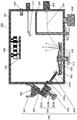
- FIG. 2 is a cross-sectional view showing a schematic configuration of a film forming apparatus for forming a protective film for PDP using the film forming material supply apparatus in the first embodiment.
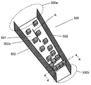
- FIG. 3 is a perspective view showing a configuration of a shooter in a conventional film forming material supply apparatus.
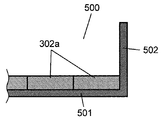
- 4 is a partial cross-sectional view taken along line 4-4 shown in FIG.
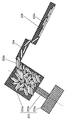
- FIG. 5 is a cross-sectional view showing details of pellet supply from the feeder to the shooter in the film forming material supply apparatus.
- FIG. 6 is a perspective view of a shooter of the film forming material supply apparatus according to the first embodiment.
- 7A is a sectional view taken along line 7A-7A in FIG.
- FIG. 7B is a cross-sectional view taken along line 7B-7B in FIG.
- FIG. 8 is a diagram showing the relationship between the angle of the side surface portion of the shooter and the bridge occurrence probability in the first embodiment.
- FIG. 9 is a perspective view showing the shooter in the second embodiment.
- 10A is a sectional view taken along line 10A-10A in FIG. 10B is a cross-sectional view taken along line 10B-10B of FIG.
- FIG. 11 is a perspective view showing the configuration of the shooter and the hearth of the film forming material supply apparatus according to the third embodiment.
- FIG. 12A is a front view showing the configuration of the shooter. 12B is an enlarged cross-sectional view taken along line 12B-12B in FIG. 12A.
- FIG. 12C is an enlarged cross-sectional view showing details of a portion I in FIG. 12A.
- FIG. 13A is a front view showing a configuration of a shooter of a film forming material supply apparatus according to Embodiment 4.
- 13B is a cross-sectional view taken along line 13B-13B of FIG. 13A.
- FIG. 14 is a perspective view showing the configuration of the shooter and the hearth of the film forming material supply apparatus in the fifth embodiment.
- FIG. 15A is a plan view of the shooter.
- FIG. 15B is a side view of the shooter.
- FIG. 16 is a cross-sectional view showing the positional relationship between the shooter and the hearth.
- FIG. 17 is a front view of the shooter as seen from the front of the hearth.
- FIG. 1 is a perspective view showing the structure of an AC type PDP 100.
- a front plate 102 made of a front glass substrate 103 and the like and a back plate 110 made of a back glass substrate 111 and the like are arranged to face each other, and an outer peripheral portion thereof is made of glass frit or the like
- the material is hermetically sealed.
- the discharge space 116 inside the sealed PDP 100 is filled with a discharge gas such as xenon (Xe) and neon (Ne) at a pressure of about 66500 Pa.
- a discharge gas such as xenon (Xe) and neon (Ne)
- a plurality of pairs of strip-shaped display electrodes 106 and black stripes (light-shielding layers) 107 made up of the scanning electrodes 104 and the sustain electrodes 105 are arranged in parallel to each other.
- a dielectric layer 108 is formed so as to hold a charge so as to cover the display electrode 106 and the light shielding layer 107 and function as a capacitor, and a protective film 109 is further formed thereon. .
- a plurality of strip-like address electrodes 112 are arranged in parallel to each other in a direction orthogonal to the scan electrodes 104 and the sustain electrodes 105 of the front plate 102, and these are arranged as a base dielectric.
- Layer 113 is covering.
- a partition wall 114 having a predetermined height is formed on the base dielectric layer 113 between the address electrodes 112 to divide the discharge space 116.
- a phosphor layer 115 that emits red, green, and blue light by ultraviolet rays is formed in each groove between the barrier ribs 114.
- a discharge space 116 is formed at a position where the scan electrode 104, the sustain electrode 105, and the address electrode 112 intersect, and the discharge space 116 having red, green, and blue phosphor layers 115 arranged in the direction of the display electrode 106 is used for color display. It becomes a pixel for.
- FIG. 2 is a cross-sectional view showing a schematic configuration of a film forming apparatus 300 for forming the protective film 109 for the PDP 100 using the film forming material supply apparatus 200 in the first embodiment.
- the film forming apparatus 300 is an electron beam (EB) vapor deposition apparatus that heats, melts and deposits a film forming material 302 with an electron beam 305.
- EB electron beam
- a hearth 303 filled with a film forming material 302 is disposed inside a vacuum chamber 301 that is a vacuum tank.
- An electron beam source 304 is installed on the side wall of the vacuum chamber 301, and the film forming material 302 on the hearth 303 is irradiated with the electron beam 305 from the electron beam source 304.
- the irradiation position of the electron beam 305 is controlled by controlling an electromagnet (not shown) by a magnetic circuit arranged on the side surface of the hearth 303.
- an exhaust pump 306 for evacuating the vacuum chamber 301, a vacuum gauge 307 for measuring the degree of vacuum, and the like are provided.
- a front plate 102 in which a display electrode 106, a black stripe (light-shielding layer) 107, and a dielectric layer 108 are formed on the front glass substrate 103 of the PDP 100 is installed almost above the hearth 303.
- a heater 308 is provided above the face plate 102 for heating the front plate 102 during film formation.
- a shutter plate 309 is provided between the front plate 102 and the hearth 303. By rotating the shutter plate 309, the vapor deposition particles 310 are inadvertently attached to the front plate 102 at a timing other than during film formation. Try to prevent.
- the film thickness of the protective film 109 formed on the front plate 102 is measured by the film thickness monitor 311 as needed.
- a thin film of magnesium oxide (MgO) is used as the protective film 109 of the PDP 100. Therefore, in the embodiment of the present invention, a material mainly composed of magnesium oxide (MgO) is used as the film forming material 302.
- the film forming material 302 accommodated in the hearth 303 is irradiated with the electron beam 305 to evaporate the film forming material 302, and the vapor deposition particles 310 are vapor-deposited on the dielectric layer 108 of the front plate 102. Form.
- the hearth 303 is configured to be rotatable by a rotating shaft 312, and the position where the film forming material 302 is supplied to the hearth 303 is different from the position where the electron beam 305 is irradiated. I try to make it.
- the film forming material 302 in the hearth 303 is consumed by heating and evaporation accompanying the film formation. Therefore, a film forming material supply apparatus 200 for supplying the film forming material 302 to the film forming apparatus 300 is connected.
- the film forming material supply apparatus 200 includes a material hopper 201, a feeder 203 disposed immediately below the discharge port 202 of the material hopper 201, and a shooter 205 connected to the feeder discharge port 204 of the feeder 203.
- the material hopper 201 and the feeder 203 are installed in a vacuum chamber (not shown) that has been evacuated.
- the vacuum chamber is a preliminary vacuum chamber that removes moisture adsorbed on magnesium oxide (MgO), which is the film forming material 302, and minimizes a decrease in the degree of vacuum in the vacuum chamber 301 when the film forming material 302 is supplied. It becomes.
- MgO magnesium oxide
- an opening / closing valve (not shown) is provided at the discharge port 202 of the material hopper 201 of the film forming material supply apparatus 200, and the introduction of the film forming material 302 into the feeder 203 is controlled by opening / closing the opening / closing valve.
- the feeder 203 includes a drive motor 203a at the lower portion thereof, and is connected to a screw (not shown) in a container 203c in which a drive shaft 203b of the drive motor 203a is inclined. Yes.
- the screw in the container 203c By the rotation of the screw in the container 203c, the film forming material 302 put into the container 203c of the feeder 203 from the material hopper 201 is conveyed from the bottom to the top of the container 203c.
- the container 203c is inclined to fall to the shooter 205 from the feeder discharge port 204 on the upper end surface.
- the supply amount of the film formation material 302 to the shooter 205 that is, the supply amount of the film formation material 302 to the hearth 303 can be controlled by controlling the number of revolutions of the drive motor 203a.
- a necessary amount of pellets of magnesium oxide (MgO), which is the film forming material 302 is stored in accordance with the period of continuous operation. For example, when the film forming apparatus 300 is continuously operated for a predetermined period, the film forming material 302 corresponding to the amount consumed by the hearth 303 during that period is stored in the material hopper 201.
- MgO magnesium oxide
- the lower part of the material hopper 201 has a funnel shape, and the supply to the feeder 203 is controlled by controlling the opening and closing of the on-off valve provided at the discharge port 202, so that the amount of the film forming material 302 in the container 203c is always substantially constant. It is controlled to become.
- the feeder 203 is provided with a ribbon-like screw that rotates on the inner peripheral surface of the container 203c with its axis inclined, and is connected to the drive motor 203a by the drive shaft 203b.
- the container 203c is arranged such that its central axis is inclined at an angle of 50 to 60 degrees with respect to the horizontal plane.
- the film forming material 302 supplied to the container 203c of the feeder 203 is transferred to the upper side of the container 203c by the rotation of the screw, falls from the feeder discharge port 204 on the lowest upper end surface of the container 203c, and falls to the upper end of the shooter 205.
- a predetermined amount is supplied to the unit 205a.
- the shooter 205 is disposed so as to incline from the container 203c toward the hearth 303 as a whole so that the upper end portion 205a is located at the upper end surface of the container 203c and the lower end portion 205b is located at the hearth 303. That is, the film forming material 302 supplied to the upper end portion 205 a of the shooter 205 is supplied to the hearth 303 while sliding down on the shooter 205.
- FIG. 3 is a perspective view showing a configuration of a shooter 500 in a conventional film forming material supply apparatus.
- 4 is a partial cross-sectional view taken along line 4-4 shown in FIG.
- the shooter 500 is constituted by a thin plate member or the like, and a bottom surface portion 501 that is a surface on which the pellet 302a as the film forming material 302 slides in the direction of arrow A, and a guide when the pellet 302a slides It is comprised by the side part 502 provided in the both sides of the bottom face part 501 which plays the role of a board.
- the passage area formed by the side surface portion 502 is reduced from the upper end portion 500a to the lower end portion 500b of the shooter 500, and the film forming material 302 is reliably supplied to a predetermined position of the hearth 303. I am doing so.
- the side surface portion 502 is configured to rise substantially perpendicularly to the bottom surface portion 501 by sheet metal bending or the like.
- the protective film 109 of the PDP 100 is formed of a material mainly composed of magnesium oxide (MgO). Therefore, as the film forming material 302, a pellet 302a such as a sintered body whose material is adjusted using magnesium oxide (MgO) as a main component material is used.
- a pellet 302a such as a sintered body whose material is adjusted using magnesium oxide (MgO) as a main component material is used.
- the shape of the pellet 302a various shapes are conceivable depending on its manufacturing method or processing method, and a spherical shape, a cylindrical shape, a plate shape, or the like is conceivable.
- the pellet 302a When the shape of the pellet 302a is spherical, the pellet 302a can slide down on the shooter 500 stably.
- a frictional force acts between the bottom surface portion 501 of the shooter 500 and the flat surface of the pellet 302a in FIG. Therefore, resistance is generated between the shooter 500 and the pellet 302a, and it is difficult to slide down.
- the magnesium oxide (MgO) can easily adsorb moisture. Therefore, even when moisture is removed in the vacuum chamber in which the material hopper 201 or the like is accommodated, the resistance at the time of sliding increases due to moisture adhering to the surface of the pellet 302a.
- such a phenomenon is caused when the side surface portion 502 serving as a guide plate provided on the shooter 500 is configured to rise at an angle of 90 degrees or less with respect to the bottom surface portion 501, that is, on both side surfaces. This is noticeable when the pellet 302a is guided inside the shooter 500 by the portion 502.
- FIG. 5 is a cross-sectional view showing details of the supply of pellets 302a from the feeder 203 to the shooter 205 in the film forming material supply apparatus 200, and schematically shows a case where a large amount of pellets 302a is supplied from the material hopper 201 to the feeder 203. Yes.
- FIG. 6 is a perspective view of shooter 215 of film forming material supply apparatus 200 in the first embodiment.
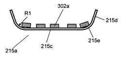
- 7A is a cross-sectional view taken along the line 7A-7A in FIG. 6, and shows an upper end portion 215a of the shooter 215.
- FIG. 7B is a cross-sectional view taken along line 6D-6D of FIG. 6, and shows a lower end portion 215b of the shooter 215.
- a pellet 302a having the same plane as that used in the conventional shooter 500 of FIG. 3 is used as the film forming material 302
- a pellet 302a having the same plane as that used in the conventional shooter 500 of FIG. 3 is used.
- the shooter 215 of the film forming material supply apparatus 200 according to Embodiment 1 is provided on the both sides of the bottom surface portion 215c that serves as a surface on which the pellet 302a is slid down and the bottom surface portion 215c.
- the bottom surface portion 215c and the side surface portion 215d are connected by the arc-shaped portion 215e. Further, the width of the bottom surface portion 215c is reduced toward the arrow A which is the sliding direction of the pellet 302a, so that the shape of the bowl is formed as a whole.
- the radius of the arc-shaped portion 215e differs for the continuity between the upper end 215a and the lower end 215b, and the radius R2 of the lower end 215b may be smaller than the radius R1 of the upper end 215a.
- the radius R2 of the arc-shaped portion 215e at the lower end 215b is important for the purpose of suppressing the bridging phenomenon of the pellet 302a at the lower end 215b.
- the radius R2 is determined by the relationship with the shape and size of the pellet 302a. For example, when the pellet 302a is 5 mm square to 20 mm square and the plate thickness is 1 mm to 5 mm, the radius R2 is preferably 10 mm or more. Have confirmed.
- the bottom surface portion 215c and the side surface portion 215d of the shooter 215 are connected by the arc-shaped portion 215e. Therefore, as shown in FIG. 7B, even if the pellet 302a is aligned in the width direction at the bottom surface portion 215c at the lower end portion 215b of the shooter 215, the end portion of the pellet 302a is present due to the arc-shaped portion 215e. Receives a force in the upward direction E along the arc. Therefore, a force that presses the pellet 302a inward of the shooter 215 is not generated by the side surface portion 215d and the pellet 302a.
- the pellets 302a can be continuously slid down and a stable protective film 109 can be formed.
- the adsorbed moisture makes it easy for the pellet 302a to adhere to the bottom surface portion 215c of the shooter 215, but according to the shooter 215 according to Embodiment 1.
- the bridge phenomenon of the pellet 302a can be suppressed even under these circumstances.
- the side surface portion 215d is preferably configured to have an obtuse angle of more than 90 degrees with respect to the bottom surface portion 215c. According to such a configuration, even if the pellet 302a is aligned in the width direction on the bottom surface portion 215c of the shooter 215, the end portion of the pellet 302a contacting the side surface portion 215d always receives an upward force. As a result, the side portion 215d and the pellet 302a do not generate a force that presses the pellet 302a inward of the shooter 215, and further suppresses the occurrence of a bridging phenomenon that the pellet 302a is aligned and blocked on the shooter 215. Can do.
- FIG. 8 is a diagram showing the relationship between the angle of the side surface portion 215d of the shooter 215 and the bridge occurrence probability in the first embodiment.
- the number of times that the bridge phenomenon occurs is experimentally obtained with respect to the angle ⁇ formed by the side surface portion 215d and the bottom surface portion 215c, and the angle ⁇ is 180 degrees, that is, the case where there is no side surface portion 215d is shown as 1. .
- the connection between the bottom surface 215c and the side surface 215d was not actively provided with the arc-shaped portion 215e, and the experiment was performed using a sheet metal processing in which the radius R of the connection is 1 mm or less.
- the pellet 302a in this case is a rectangular parallelepiped pellet 302a having a size of 5 mm ⁇ 7 mm and a thickness of 2 mm, and the radius R of the ridge portion on each side of the pellet 302a is 0.5 mm.
- the result of FIG. 8 is a result that the arc-shaped portion 215e is not actively provided at the connection portion between the bottom surface portion 215c and the side surface portion 215d, and as described above, when the arc-shaped portion 215e having R2 of 10 mm is provided. Even if the angle ⁇ is 90 degrees, the occurrence of the bridging phenomenon can be suppressed.
- the pellet 302a to be the film forming material 302 is a plate-like material having a predetermined thickness and the thickness is T1
- the height H1 from the bottom surface portion 215c of the side surface portion 215d is greater than T1. It is desirable to increase the size. According to such a configuration, the pellet 302a that moves to the upper side of the shooter 215 along the arc-shaped portion 215e and the side surface portion 215d can be prevented from sliding off the shooter 215 beyond the side surface portion 215d.
- the bridge phenomenon of the pellet 302a is suppressed by the side surface portion 215d disposed with an obtuse angle ⁇ with respect to the arc-shaped portion 215e and the bottom surface portion 215c, and the pellet 302a stably slides down on the shooter 215. is doing.
- the height H1 is determined by the relationship with the shape and size of the pellet 302a.
- H1 is desirably 10 mm or more.
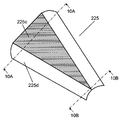
- FIG. 9 is a perspective view showing a shooter 225 in the film forming material supply apparatus 200 according to the second embodiment.
- 10A is a cross-sectional view taken along the line 10A-10A in FIG. 9, and shows the upper end portion of the shooter 225.
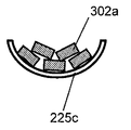
- 10B is a cross-sectional view taken along the line 10B-10B in FIG. 9, and shows a lower end portion of the shooter 225.
- the shooter 225 in the second embodiment does not have a flat surface portion like the bottom surface portion 215c of the shooter 215 shown in FIG. That is, in the shooter 225, the bottom surface portion 225c and the side surface portion 225d are formed in a continuous arc shape so that the shooter 225 does not have a surface in surface contact with the flat portion of the pellet 302a.
- the supply of pellets 302a can be more stably realized by adopting a configuration in which there is no flat portion in the lower end portion of the shooter 225, that is, the region near the supply end portion to the hearth 303. Even in such a configuration, since the force for pressing the pellet 302a toward the inside of the shooter 225 is not generated, the occurrence of the bridge phenomenon can be further suppressed.
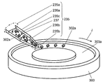
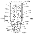
- FIG. 11 is a perspective view showing a configuration of shooter 235 and hearth 303 of film forming material supply apparatus 200 in the third embodiment.
- 12A is a front view showing the configuration of the shooter 235
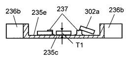
- FIG. 12B is an enlarged cross-sectional view taken along the line 12B-12B of FIG. 12A
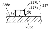
- FIG. 12C is an enlarged cross-sectional view showing details of the I portion of FIG. Note that the case where a plate-shaped pellet 302a is used as the film forming material 302 is described.
- a material receiving portion 303a having a predetermined depth is provided in a concentric shape on the upper surface of a hearth 303 that constitutes a rotating body as a whole, and the material receiving portion is obtained by rotating the hearth 303 in the arrow J direction.
- 303a is also configured to rotate in the direction of arrow J.
- the shooter 235 is inclined with respect to the horizontal surface of the hearth 303 from the upper end 235a toward the lower end 235b, and the lower end 235b is arranged to open toward the material receiving portion 303a. ing.
- the shooter 235 is configured as shown in FIG. 12A. That is, the shooter 235 is configured by a thin plate member or the like, and is provided on both sides of the bottom surface portion 235c that serves as a surface on which the pellet 302a that is the film forming material 302 slides, and the bottom surface portion 235c that serves as a guide plate when the pellet 302a slides. It is comprised by the side part 235d provided in this. Further, the side surface portion 235d is composed of a side surface portion 236a and a side surface portion 236b. The pellet 302a slides down on the shooter 235 in the direction of arrow A, and the passage area of the shooter 235 is reduced by the left and right side portions 236b.
- the height of the side surface portion 235d from the bottom surface portion 235c is not less than the maximum length of the pellet 302a, which is the film forming material 302, so that the pellet 302a does not fall out of the shooter 235 over the side surface portion 235d. It is desirable to do.
- the bottom surface portion 235c of the shooter 235 of the film forming material supply apparatus 200 according to Embodiment 3 has the pellet 302a as the bottom surface portion when the bottom surface portion 235c slides down.
- a protrusion 237 that is lifted from 235c is provided.
- a plurality of protrusions 237 are provided at predetermined positions on the bottom surface portion 235c of the shooter 235.
- the protruding portion 237 is erected with respect to the flat surface portion 235e of the bottom surface portion 235c and is connected to the flat surface portion 235e with a predetermined R shape. It is comprised by 237a and the convex part 237b.
- the R-shaped portion 237a provided on the protrusion 237 is configured to lift the pellet 302a that slides down while sliding on the flat portion 235e from the flat portion 235e of the bottom surface portion 235c.
- the bridging phenomenon of the pellets 302a occurs when the adjacent pellets 302a are constrained in the plane direction parallel to the bottom surface portion 235c, and all of them are constrained by the side surface portion 235d of the shooter 235. To do.
- these restraints can be suppressed. That is, among the pellets 302a that slide down while sliding on the flat surface portion 235e, the pellet 302a that hits the protruding portion 237 is lifted upward in the upward direction by the R-shaped portion 237a provided on the protruding portion 237. . As a result, as shown in FIG. 12B, the adjacent pellets 302a are not restrained in the same plane direction. Therefore, even if restrained by the side surface portion 235d, the pellets 302a are not aligned and restrained in the width direction of the bottom surface portion 235c, that is, in the direction of the line 12B-12B in FIG. 12A.
- the size of the radius R of the R-shaped portion 237a is determined by the relationship with the shape of the pellet 302a that is the film forming material 302, particularly when the pellet 302a has a flat plate shape, depending on the edge shape of the end portion of the pellet 302a.
- the edge shape is a right angle
- an R shape having a larger curvature is desirable.
- the curvature may be small. That is, the pellet 302a that hits the protrusion 237 by sliding down may have a shape that changes the direction upward along the protrusion 237 by the R-shaped portion 237a and lifts the pellet 302a.
- the radius R of the corner portion may be equal to or greater than the thickness T1 that is the minimum length of the flat plate.
- the height T2 of the protrusion 237 from the flat portion 235e is desirably at least the thickness T1 of the pellet 302a.
- At least one protrusion 237 is provided in an area 238 that is orthogonal to the arrow A, which is the direction in which the pellet 302a of the bottom surface portion 235c slides, and has the maximum length of the pellet 302a.
- the pellet 302a is a flat plate having a substantially square plane, and the maximum length in this case is a square diagonal line. According to such a configuration, at least one pellet 302a is lifted from the bottom surface portion 235c in the 12B-12B direction perpendicular to the direction in which the pellet 302a slides down, and thus is constrained and aligned by the side surface portions 235d on both sides. There is no longer to do.
- the protrusion 237 may be provided over the entire length of the pellet 302a in the sliding direction, but may be provided particularly only in the vicinity of the lower end 235b of the shooter 235.
- the shape of the protruding portion 237 is not limited to the above shape, and may be configured to have a tapered portion in the sliding direction, for example. With such a configuration, when the bottom surface portion 235c is slid down, the pellet 302a can ride on the tapered portion, and the pellet 302a can be lifted from the bottom surface portion 235c.
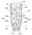
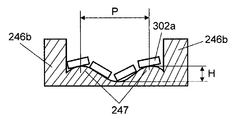
- FIG. 13A is a front view showing the configuration of the shooter 245 of the film forming material supply apparatus 200 according to Embodiment 4, and FIG. 13B is a cross-sectional view taken along line 13B-13B of FIG. 13A.
- the basic configuration of shooter 245 in the fourth embodiment is the same as that of shooter 235 in the third embodiment shown in FIG. 12A. That is, the shooter 245 is configured by a thin plate member or the like, and is provided on both sides of a bottom surface portion 245c that serves as a surface on which the pellet 302a that is the film forming material 302 slides down and a bottom surface portion 245c that serves as a guide plate when the pellet 302a slides down. It is comprised by the side part 245d provided in this. Further, the side surface portion 245d is composed of a side surface portion 246a and a side surface portion 246b. The pellet 302a slides down on the shooter 245 in the direction of arrow A, and the passage area is reduced by the left and right side portions 246b.
- the shooter 245 in the fourth embodiment is different from the third embodiment in the configuration of the bottom surface portion 245c. That is, as shown in FIGS. 13A and 13B, the bottom surface portion 245c of the shooter 245 is provided with corrugated protrusions 247 in a direction orthogonal to the direction in which the pellet 302a slides down.
- the corrugated protrusions 247 are configured to have a predetermined pitch P and a predetermined amplitude H, and are formed by bending a thin plate member in the fourth embodiment.
- the corrugated protrusions 247 are continuously formed in a stripe shape from the upper end 245a to the lower end 245b of the shooter 245.
- the corrugated protrusion 247 By providing the corrugated protrusion 247, it is possible to suppress the occurrence of a bridging phenomenon of the pellet 302a that slides down the shooter 245. That is, as described in the third embodiment, the bridging phenomenon of the pellets 302a is caused by the fact that the adjacent pellets 302a are constrained in the plane direction in which the end portions of the pellets 302a are parallel to the bottom surface portion 245c. It is generated by being restrained by the side surface portion 245d of 245.
- the corrugated protrusion 247 in the fourth embodiment these constraints can be suppressed. That is, the pellet 302a that slides down while sliding on the bottom surface portion 245c slides along the surface of the corrugated protrusion 247, as shown in FIGS. 13A and 13B, and ends of the adjacent pellets 302a. The parts are not restrained on the same plane. Therefore, even when restrained by the side surface portion 245d, the pellets 302a are not aligned and restrained in the width direction of the bottom surface portion 245c, that is, in the direction of the line 13B-13B in FIG. 13A.
- the pitch P and the amplitude H of the corrugated protrusions 247 are determined by the relationship with the shape of the pellet 302 a that is the film forming material 302. Specifically, when the pellet 302a has a flat plate shape, the pitch P is desirably greater than or equal to the plane diagonal dimension W which is the maximum dimension of the pellet 302a, and the amplitude H is equal to or greater than the thickness T1 of the pellet 302a which is the minimum dimension. It is desirable that
- the corrugated protrusion 247 is provided over the entire length of the shooter 245 in the sliding direction of the pellet 302a, but is provided only in the vicinity of the lower end 245b of the shooter 245 where the bridging phenomenon is likely to occur. Also good.
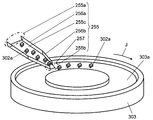
- FIG. 14 is a perspective view showing the configuration of shooter 255 and hearth 303 of film forming material supply apparatus 200 in the fifth embodiment.
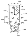
- 15A is a plan view of the shooter 255
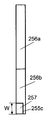
- FIG. 15B is a side view thereof.
- 16 is a sectional view showing the positional relationship between the shooter 255 and the hearth 303
- FIG. 17 is a front view of the shooter 255 as seen from the front of the hearth 303.
- the film forming material 302 is described using a plate-shaped pellet 302a.
- a material receiving portion 303a having a predetermined depth is provided in a concentric shape on the upper surface of a hearth 303 that entirely constitutes a rotating body, and the material receiving portion is obtained by rotating the hearth 303 in the direction of arrow J.
- 303a is also configured to rotate in the direction of arrow J.
- the shooter 255 is inclined with respect to the horizontal surface of the hearth 303 from the upper end portion 255a toward the lower end portion 255b, and the lower end portion 255b opens toward the material receiving portion 303a. Is arranged.
- the pellet 302a is shown only in a part of the material receiving portion 303a, but the pellet 302a is filled in the entire region of the material receiving portion 303a.
- the shooter 255 is configured as shown in FIGS. That is, the shooter 255 is constituted by a thin plate member or the like, and a bottom surface portion 255c serving as a surface on which the pellet 302a as the film forming material 302 slides in the direction of arrow A, and a bottom surface serving as a guide plate when the pellet 302a slides down. It is comprised by the side part 255d provided in the both ends of the part 255c.
- the side surface portion 255d is composed of the side surface portion 256a and the side surface portion 256b, the passage area formed by the left and right side surface portions 256b is reduced toward the lower end portion 255b, and the pellet is placed at a predetermined position of the material receiving portion 303a. 302a is configured to slide down.
- At least one of the left and right side surface portions 256b of the lower end portion 255b is provided with a notch portion 257 in which the side surface portion 256b is notched. As shown in FIG. 15B, it is desirable to provide a notch portion 257 so that the bottom surface portion 255c is exposed when the shooter 255 is viewed from the side.
- the height of the side surface portion 255d from the bottom surface portion 255c is preferably equal to or greater than the maximum length of the pellet 302a so that the pellet 302a does not fall out of the shooter 255 over the side surface portion 255d. Further, it is desirable that the width W of the notch 257 is at least the maximum length of the pellet 302a.
- the lower end portion 255b of the shooter 255 is arranged so that the pellet 302a is slid down on the material receiving portion 303a provided in the hearth 303, and the notch portion 257 is also located in the region of the material receiving portion 303a. It arrange
- the shooter 255 of the film forming material supply apparatus 200 is configured such that the cutout portion 257 is provided in at least one of the side surface portions 256b at the lower end portion 255b of the shooter 255. Therefore, at the lower end portion 255b, the pellet 302a is not restrained by the side surface portions 256b on both sides. That is, the pellet 302 a can be discharged from the notch 257 to the outside of the shooter 255. Therefore, the bridge phenomenon does not occur on the bottom surface portion 255c of the shooter 255. As a result, the pellet 302a can be stably slid down on the shooter 255 and stably supplied to the hearth 303, and the protective film 109 can be stably formed.
- the notch portion 257 is opened toward the material receiving portion 303 a provided in the hearth 303. That is, the outermost end portion 258 of the notch portion 257 is positioned so as to be inside the end portion 303b of the material receiving portion 303a. Therefore, the pellet 302a discharged from the shooter 255 can be reliably slid down to the material receiving portion 303a, and the use efficiency of the pellet 302a is not reduced.
- the center of the longitudinal direction of the shooter 255 is relative to the material receiving portion 303a so that the pellet 302a falling from the lower end portion 255b and the notch portion 257 of the shooter 255 is surely dropped to the material receiving portion 303a. It is desirable that they are arranged so as to be inclined with respect to the material receiving portion 303a instead of being orthogonal to each other.
- the notch portion 257 provided in the shooter 255 is rotated by the material receiving portion 303a of the side surface portions 256b on both sides. It is provided only on the downstream side in the direction of movement. According to such a configuration, the pellet 302a overflowed and discharged from the notch 257 in order to avoid the bridge phenomenon can be slid down to the material receiving portion 303a on the downstream side of the shooter 255. For this reason, the pellet 302a overflowing from the notch portion 257 does not cause a phenomenon that obstructs the rotation of the hearth 303 by closing the gap between the shooter 255 and the material receiving portion 303a.
- FIG. 17 is a front view of the shooter 255 as viewed from the front of the hearth 303.
- bottom surface portion 255 c particularly bottom surface portion 255 c at lower end portion 255 b is inclined with respect to the surface of hearth 303.
- the lower end portion 255b is inclined so that the distance H1 between the hearth 303 and the shooter 255 at the side surface portion 256b on the side where the notch portion 257 is provided is larger than the distance H2 on the opposite side.
- the pellet 302a can be accurately slid down to a predetermined position of the material receiving portion 303a of the hearth 303.
- the pellet 302a is surely overflowed from the notch portion 257 to suppress the occurrence of the bridge phenomenon. Can do.
- FIG. 17 shows an example in which the side surface portion 256b on the side where the notch portion 257 is provided is inclined so as to increase, but the side surface portion 256b on the side where the notch portion 257 is provided is made lower.
- the pellet 302a may be slid down from the notch portion 257 to the material receiving portion 303a even at the normal time.
- magnesium oxide (MgO) is targeted as a film forming material, but the material is not limited to magnesium oxide (MgO). Further, the present invention is not limited to the supply of the PDP protective film material.
- the film forming material can be stably supplied to the film forming apparatus, and the film forming apparatus can be stably operated continuously. Applicable.
Landscapes
- Chemical & Material Sciences (AREA)
- Chemical Kinetics & Catalysis (AREA)
- Engineering & Computer Science (AREA)
- Materials Engineering (AREA)
- Mechanical Engineering (AREA)
- Metallurgy (AREA)
- Organic Chemistry (AREA)
- Physical Vapour Deposition (AREA)
Abstract
Priority Applications (3)
| Application Number | Priority Date | Filing Date | Title |
|---|---|---|---|
| JP2010502104A JPWO2010050166A1 (ja) | 2008-10-27 | 2009-10-26 | 成膜材料供給装置 |
| US12/677,148 US20110214966A1 (en) | 2008-10-27 | 2009-10-26 | Film forming material feeding apparatus |
| CN200980100452A CN101802252A (zh) | 2008-10-27 | 2009-10-26 | 成膜材料供给装置 |
Applications Claiming Priority (6)
| Application Number | Priority Date | Filing Date | Title |
|---|---|---|---|
| JP2008-275111 | 2008-10-27 | ||
| JP2008-275112 | 2008-10-27 | ||
| JP2008-275110 | 2008-10-27 | ||
| JP2008275111 | 2008-10-27 | ||
| JP2008275112 | 2008-10-27 | ||
| JP2008275110 | 2008-10-27 |
Publications (1)
| Publication Number | Publication Date |
|---|---|
| WO2010050166A1 true WO2010050166A1 (fr) | 2010-05-06 |
Family
ID=42128536
Family Applications (1)
| Application Number | Title | Priority Date | Filing Date |
|---|---|---|---|
| PCT/JP2009/005620 Ceased WO2010050166A1 (fr) | 2008-10-27 | 2009-10-26 | Dispositif d’alimentation en matériau filmogène |
Country Status (5)
| Country | Link |
|---|---|
| US (1) | US20110214966A1 (fr) |
| JP (1) | JPWO2010050166A1 (fr) |
| KR (1) | KR20100071996A (fr) |
| CN (1) | CN101802252A (fr) |
| WO (1) | WO2010050166A1 (fr) |
Families Citing this family (3)
| Publication number | Priority date | Publication date | Assignee | Title |
|---|---|---|---|---|
| KR101461738B1 (ko) * | 2012-12-21 | 2014-11-14 | 주식회사 포스코 | 가열장치 및 이를 포함하는 코팅 시스템 |
| CN109502231A (zh) * | 2017-09-14 | 2019-03-22 | 安莉芳(中国)服装有限公司 | 一种缓冲输送滑槽 |
| CN120400773A (zh) * | 2021-11-19 | 2025-08-01 | 芝浦机械电子装置株式会社 | 供给装置及成膜装置 |
Citations (5)
| Publication number | Priority date | Publication date | Assignee | Title |
|---|---|---|---|---|
| JPS6227219A (ja) * | 1985-07-24 | 1987-02-05 | Japan Crown Cork Co Ltd | 物品供給装置 |
| JPH01159934U (fr) * | 1988-04-27 | 1989-11-07 | ||
| JPH06322521A (ja) * | 1993-05-13 | 1994-11-22 | Toyobo Co Ltd | 連続蒸着方法およびその装置 |
| JP2006045589A (ja) * | 2004-07-30 | 2006-02-16 | Ulvac Japan Ltd | 成膜材料供給装置 |
| JP2007113058A (ja) * | 2005-10-19 | 2007-05-10 | Ulvac Japan Ltd | 成膜材料供給装置 |
-
2009
- 2009-10-26 WO PCT/JP2009/005620 patent/WO2010050166A1/fr not_active Ceased
- 2009-10-26 KR KR1020107005970A patent/KR20100071996A/ko not_active Ceased
- 2009-10-26 CN CN200980100452A patent/CN101802252A/zh active Pending
- 2009-10-26 JP JP2010502104A patent/JPWO2010050166A1/ja not_active Withdrawn
- 2009-10-26 US US12/677,148 patent/US20110214966A1/en not_active Abandoned
Patent Citations (5)
| Publication number | Priority date | Publication date | Assignee | Title |
|---|---|---|---|---|
| JPS6227219A (ja) * | 1985-07-24 | 1987-02-05 | Japan Crown Cork Co Ltd | 物品供給装置 |
| JPH01159934U (fr) * | 1988-04-27 | 1989-11-07 | ||
| JPH06322521A (ja) * | 1993-05-13 | 1994-11-22 | Toyobo Co Ltd | 連続蒸着方法およびその装置 |
| JP2006045589A (ja) * | 2004-07-30 | 2006-02-16 | Ulvac Japan Ltd | 成膜材料供給装置 |
| JP2007113058A (ja) * | 2005-10-19 | 2007-05-10 | Ulvac Japan Ltd | 成膜材料供給装置 |
Also Published As
| Publication number | Publication date |
|---|---|
| JPWO2010050166A1 (ja) | 2012-03-29 |
| KR20100071996A (ko) | 2010-06-29 |
| CN101802252A (zh) | 2010-08-11 |
| US20110214966A1 (en) | 2011-09-08 |
Similar Documents
| Publication | Publication Date | Title |
|---|---|---|
| JPWO2010050166A1 (ja) | 成膜材料供給装置 | |
| KR20050039240A (ko) | 보호막을 개선한 플라즈마 디스플레이 패널 | |
| US7956540B2 (en) | Plasma display panel | |
| JP2000001771A (ja) | 誘電体保護層の製造方法とその製造装置、並びにそれを用いたプラズマディスプレイパネルと画像表示装置 | |
| US7795811B2 (en) | Plasma display panel | |
| JP2010116595A (ja) | 成膜材料供給装置 | |
| JP2011105966A (ja) | 成膜材料供給装置 | |
| US8163085B2 (en) | Method and apparatus for forming protective layer | |
| US20060033448A1 (en) | Plasma display panel (PDP) | |
| JP2010212171A (ja) | プラズマディスプレイパネルの製造方法 | |
| US20090155457A1 (en) | Die coater and method for fabricating plasma-display-panel substrate assembly | |
| JP4626035B2 (ja) | プラズマディスプレイ装置の製造方法 | |
| JP2010037610A (ja) | 成膜材料 | |
| JP4381649B2 (ja) | プラズマディスプレイパネルの製造方法および誘電体保護膜製造装置 | |
| JP2010037609A (ja) | 成膜材料 | |
| JP2010037608A (ja) | 成膜材料 | |
| US7595589B2 (en) | Plasma display panel | |
| JP2010059461A (ja) | 成膜装置 | |
| KR100759444B1 (ko) | 플라즈마 디스플레이 패널 | |
| KR100768001B1 (ko) | 플라즈마 디스플레이 패널 | |
| US8148899B2 (en) | Plasma display panel and method for manufacturing the same | |
| KR20050034312A (ko) | 개선된 보호막을 가진 플라즈마 디스플레이 패널 | |
| JP2006059627A (ja) | プラズマディスプレイパネルの誘電体保護膜の製造方法 | |
| JP4736933B2 (ja) | プラズマディスプレイパネル | |
| KR100599594B1 (ko) | 플라즈마 디스플레이 패널용 기판 운송장치 |
Legal Events
| Date | Code | Title | Description |
|---|---|---|---|
| WWE | Wipo information: entry into national phase |
Ref document number: 200980100452.4 Country of ref document: CN |
|
| WWE | Wipo information: entry into national phase |
Ref document number: 2010502104 Country of ref document: JP |
|
| WWE | Wipo information: entry into national phase |
Ref document number: 12677148 Country of ref document: US |
|
| ENP | Entry into the national phase |
Ref document number: 20107005970 Country of ref document: KR Kind code of ref document: A |
|
| 121 | Ep: the epo has been informed by wipo that ep was designated in this application |
Ref document number: 09823279 Country of ref document: EP Kind code of ref document: A1 |
|
| NENP | Non-entry into the national phase |
Ref country code: DE |
|
| 122 | Ep: pct application non-entry in european phase |
Ref document number: 09823279 Country of ref document: EP Kind code of ref document: A1 |