WO2010055670A1 - 空気調和装置 - Google Patents
空気調和装置 Download PDFInfo
- Publication number
- WO2010055670A1 WO2010055670A1 PCT/JP2009/006073 JP2009006073W WO2010055670A1 WO 2010055670 A1 WO2010055670 A1 WO 2010055670A1 JP 2009006073 W JP2009006073 W JP 2009006073W WO 2010055670 A1 WO2010055670 A1 WO 2010055670A1
- Authority
- WO
- WIPO (PCT)
- Prior art keywords
- fan
- outdoor
- heat exchanger
- defrosting operation
- compressor
- Prior art date
- Legal status (The legal status is an assumption and is not a legal conclusion. Google has not performed a legal analysis and makes no representation as to the accuracy of the status listed.)
- Ceased
Links
Images


Classifications
-
- F—MECHANICAL ENGINEERING; LIGHTING; HEATING; WEAPONS; BLASTING
- F25—REFRIGERATION OR COOLING; COMBINED HEATING AND REFRIGERATION SYSTEMS; HEAT PUMP SYSTEMS; MANUFACTURE OR STORAGE OF ICE; LIQUEFACTION SOLIDIFICATION OF GASES
- F25B—REFRIGERATION MACHINES, PLANTS OR SYSTEMS; COMBINED HEATING AND REFRIGERATION SYSTEMS; HEAT PUMP SYSTEMS
- F25B47/00—Arrangements for preventing or removing deposits or corrosion, not provided for in another subclass
- F25B47/02—Defrosting cycles
- F25B47/022—Defrosting cycles hot gas defrosting
-
- F—MECHANICAL ENGINEERING; LIGHTING; HEATING; WEAPONS; BLASTING
- F24—HEATING; RANGES; VENTILATING
- F24F—AIR-CONDITIONING; AIR-HUMIDIFICATION; VENTILATION; USE OF AIR CURRENTS FOR SCREENING
- F24F1/00—Room units for air-conditioning, e.g. separate or self-contained units or units receiving primary air from a central station
- F24F1/06—Separate outdoor units, e.g. outdoor unit to be linked to a separate room comprising a compressor and a heat exchanger
-
- F—MECHANICAL ENGINEERING; LIGHTING; HEATING; WEAPONS; BLASTING
- F24—HEATING; RANGES; VENTILATING
- F24F—AIR-CONDITIONING; AIR-HUMIDIFICATION; VENTILATION; USE OF AIR CURRENTS FOR SCREENING
- F24F11/00—Control or safety arrangements
- F24F11/30—Control or safety arrangements for purposes related to the operation of the system, e.g. for safety or monitoring
-
- F—MECHANICAL ENGINEERING; LIGHTING; HEATING; WEAPONS; BLASTING
- F24—HEATING; RANGES; VENTILATING
- F24F—AIR-CONDITIONING; AIR-HUMIDIFICATION; VENTILATION; USE OF AIR CURRENTS FOR SCREENING
- F24F11/00—Control or safety arrangements
- F24F11/30—Control or safety arrangements for purposes related to the operation of the system, e.g. for safety or monitoring
- F24F11/41—Defrosting; Preventing freezing
- F24F11/42—Defrosting; Preventing freezing of outdoor units
-
- F—MECHANICAL ENGINEERING; LIGHTING; HEATING; WEAPONS; BLASTING
- F24—HEATING; RANGES; VENTILATING
- F24F—AIR-CONDITIONING; AIR-HUMIDIFICATION; VENTILATION; USE OF AIR CURRENTS FOR SCREENING
- F24F11/00—Control or safety arrangements
- F24F11/70—Control systems characterised by their outputs; Constructional details thereof
- F24F11/80—Control systems characterised by their outputs; Constructional details thereof for controlling the temperature of the supplied air
- F24F11/83—Control systems characterised by their outputs; Constructional details thereof for controlling the temperature of the supplied air by controlling the supply of heat-exchange fluids to heat-exchangers
- F24F11/84—Control systems characterised by their outputs; Constructional details thereof for controlling the temperature of the supplied air by controlling the supply of heat-exchange fluids to heat-exchangers using valves
-
- F—MECHANICAL ENGINEERING; LIGHTING; HEATING; WEAPONS; BLASTING
- F24—HEATING; RANGES; VENTILATING
- F24F—AIR-CONDITIONING; AIR-HUMIDIFICATION; VENTILATION; USE OF AIR CURRENTS FOR SCREENING
- F24F11/00—Control or safety arrangements
- F24F11/70—Control systems characterised by their outputs; Constructional details thereof
- F24F11/80—Control systems characterised by their outputs; Constructional details thereof for controlling the temperature of the supplied air
- F24F11/86—Control systems characterised by their outputs; Constructional details thereof for controlling the temperature of the supplied air by controlling compressors within refrigeration or heat pump circuits
-
- F—MECHANICAL ENGINEERING; LIGHTING; HEATING; WEAPONS; BLASTING
- F24—HEATING; RANGES; VENTILATING
- F24F—AIR-CONDITIONING; AIR-HUMIDIFICATION; VENTILATION; USE OF AIR CURRENTS FOR SCREENING
- F24F11/00—Control or safety arrangements
- F24F11/70—Control systems characterised by their outputs; Constructional details thereof
- F24F11/80—Control systems characterised by their outputs; Constructional details thereof for controlling the temperature of the supplied air
- F24F11/87—Control systems characterised by their outputs; Constructional details thereof for controlling the temperature of the supplied air by controlling absorption or discharge of heat in outdoor units
- F24F11/871—Control systems characterised by their outputs; Constructional details thereof for controlling the temperature of the supplied air by controlling absorption or discharge of heat in outdoor units by controlling outdoor fans
-
- F—MECHANICAL ENGINEERING; LIGHTING; HEATING; WEAPONS; BLASTING
- F24—HEATING; RANGES; VENTILATING
- F24F—AIR-CONDITIONING; AIR-HUMIDIFICATION; VENTILATION; USE OF AIR CURRENTS FOR SCREENING
- F24F2110/00—Control inputs relating to air properties
- F24F2110/10—Temperature
-
- F—MECHANICAL ENGINEERING; LIGHTING; HEATING; WEAPONS; BLASTING
- F24—HEATING; RANGES; VENTILATING
- F24F—AIR-CONDITIONING; AIR-HUMIDIFICATION; VENTILATION; USE OF AIR CURRENTS FOR SCREENING
- F24F2110/00—Control inputs relating to air properties
- F24F2110/10—Temperature
- F24F2110/12—Temperature of the outside air
-
- F—MECHANICAL ENGINEERING; LIGHTING; HEATING; WEAPONS; BLASTING
- F25—REFRIGERATION OR COOLING; COMBINED HEATING AND REFRIGERATION SYSTEMS; HEAT PUMP SYSTEMS; MANUFACTURE OR STORAGE OF ICE; LIQUEFACTION SOLIDIFICATION OF GASES
- F25B—REFRIGERATION MACHINES, PLANTS OR SYSTEMS; COMBINED HEATING AND REFRIGERATION SYSTEMS; HEAT PUMP SYSTEMS
- F25B2313/00—Compression machines, plants or systems with reversible cycle not otherwise provided for
- F25B2313/029—Control issues
- F25B2313/0294—Control issues related to the outdoor fan, e.g. controlling speed
-
- F—MECHANICAL ENGINEERING; LIGHTING; HEATING; WEAPONS; BLASTING
- F25—REFRIGERATION OR COOLING; COMBINED HEATING AND REFRIGERATION SYSTEMS; HEAT PUMP SYSTEMS; MANUFACTURE OR STORAGE OF ICE; LIQUEFACTION SOLIDIFICATION OF GASES
- F25B—REFRIGERATION MACHINES, PLANTS OR SYSTEMS; COMBINED HEATING AND REFRIGERATION SYSTEMS; HEAT PUMP SYSTEMS
- F25B2400/00—Component parts or details not otherwise provided for in this subclass
- F25B2400/01—Heaters
-
- F—MECHANICAL ENGINEERING; LIGHTING; HEATING; WEAPONS; BLASTING
- F25—REFRIGERATION OR COOLING; COMBINED HEATING AND REFRIGERATION SYSTEMS; HEAT PUMP SYSTEMS; MANUFACTURE OR STORAGE OF ICE; LIQUEFACTION SOLIDIFICATION OF GASES
- F25B—REFRIGERATION MACHINES, PLANTS OR SYSTEMS; COMBINED HEATING AND REFRIGERATION SYSTEMS; HEAT PUMP SYSTEMS
- F25B2700/00—Sensing or detecting of parameters; Sensors therefor
- F25B2700/21—Temperatures
- F25B2700/2106—Temperatures of fresh outdoor air
Definitions
- the present invention relates to an air conditioner using a vapor compression refrigeration cycle.
- the outdoor heat exchanger of the air conditioner functions as a refrigerant evaporator during heating operation, moisture contained in outdoor air is condensed on the surface of the outdoor heat exchanger.
- frost formation on the outdoor heat exchanger is remarkable, and the frost formation range extends not only to the outdoor heat exchanger but also to the outdoor fan body, the bell mouth and fan guard around the outdoor fan. It extends.
- frost covering the surface of an outdoor heat exchanger causes hot gas to be transferred to the outdoor heat exchanger during the defrosting operation. Melt by flowing.
- frost attached to the outdoor heat exchanger can be melted, but attached to the outdoor fan body, the bell mouth and the fan guard around the outdoor fan, and the like. I could't melt the frost.
- the subject of this invention is providing the air conditioning apparatus which can remove even the frost adhering to the apparatus and member located in the downstream of the airflow which heat-exchanges with an outdoor heat exchanger.
- the air conditioner according to the first aspect of the present invention includes a refrigerant circuit, a switching valve, an outdoor fan, and a control unit.
- the refrigerant circuit during the heating operation, the refrigerant circulates in the order of the compressor, the indoor heat exchanger, the decompression mechanism, and the outdoor heat exchanger.
- the switching valve is connected to the refrigerant circuit and switches the flow direction of the refrigerant discharged from the compressor.
- the outdoor fan sends air to the outdoor heat exchanger.
- the control unit performs a defrosting operation control in which the outdoor fan is stopped and the refrigerant discharged from the compressor is directed to the outdoor heat exchanger by the switching valve.
- control unit performs fan defrosting operation control for rotating the outdoor fan for a predetermined time while maintaining the operation in which the refrigerant discharged from the compressor is directed to the outdoor heat exchanger after completion of the defrosting operation when the predetermined condition is satisfied.
- frost attached to the outdoor fan main body and its peripheral members for example, bell mouth and fan guard
- this air conditioner as the outdoor fan rotates, the air passing through the outdoor heat exchanger whose temperature has risen becomes hot air and hits the outdoor fan main body and its peripheral members. Melts.
- the air conditioner according to the second aspect of the present invention is the air conditioner according to the first aspect of the present invention, further comprising an outside air temperature sensor for measuring the outside air temperature.
- the control unit executes fan defrosting operation control when the outside air temperature detected via the outside air temperature sensor is within a predetermined range. In this air conditioner, since the control unit determines whether to execute fan defrosting operation control according to the outside air temperature, useless fan defrosting operation is prevented.
- An air conditioner according to a third aspect of the present invention is the air conditioner according to the first aspect of the present invention, wherein the control unit operates the compressor during fan defrosting operation control.
- the temperature of the refrigerant flowing into the outdoor heat exchanger is maintained high by operating the compressor during fan defrosting operation control, so the temperature of warm air toward the outdoor fan body and its peripheral members is reduced. Is suppressed. As a result, the ability to defrost the outdoor fan main body and its peripheral members is improved.
- An air conditioner according to a fourth aspect of the present invention is the air conditioner according to the first aspect of the present invention, wherein the control unit operates the compressor at a specific operating frequency lower than that during the defrosting operation during the fan defrosting operation control.
- the control unit operates the compressor at a specific operating frequency lower than that during the defrosting operation during the fan defrosting operation control.
- the operation frequency of the compressor during the fan defrosting operation is preferably low. Therefore, the operation after the fan defrosting operation is smoothly performed by setting the specific operation frequency prepared for the operation after the fan defrosting operation.
- An air conditioner according to a fifth aspect of the present invention is the air conditioner according to the first aspect of the present invention, wherein a predetermined time can be selected at least at the initial setting at the installation location.
- the length of time for which the fan defrosting operation control is performed is set to a time length suitable for the climatic conditions of the installation location of the air conditioner. A state in which frost remains on the peripheral members is avoided.
- An air conditioner according to a sixth aspect of the present invention is the air conditioner according to the third or fourth aspect of the present invention, wherein the control unit stops the compressor before switching to the heating operation after the fan defrosting operation control is completed. .
- the compressor is stopped before the heating operation, whereby the pressure in the refrigerant circuit is equalized and the switching to the heating operation is performed safely.
- An air conditioner according to a seventh aspect of the present invention is the air conditioner according to the third or fourth aspect of the present invention, further comprising a refrigerant heating device that heats the refrigerant flowing through the refrigerant circuit.
- a control part operates a refrigerant heating device at the time of fan defrost operation control.
- the temperature of the refrigerant flowing into the outdoor heat exchanger is maintained high by operating the refrigerant heating device during fan defrosting operation control, so the temperature of the hot air toward the outdoor fan body and its peripheral members Reduction is suppressed. As a result, the ability to defrost the outdoor fan main body and its peripheral members is improved.
- An air conditioner according to an eighth aspect of the present invention is the air conditioner according to the seventh aspect of the present invention, wherein the refrigerant heating device is an electromagnetic induction heater.
- the refrigerant heating device is an electromagnetic induction heater.
- the control unit determines whether to execute the fan defrosting operation control according to the outside air temperature, so that useless fan defrosting operation is prevented.
- the temperature of the refrigerant flowing into the outdoor heat exchanger is maintained high by operating the compressor during fan defrosting operation control, so the temperature toward the outdoor fan body and its peripheral members is high. Wind temperature drop is suppressed.
- the specific operation frequency provided for the operation after the fan defrosting operation is set, so that the operation after the fan defrosting operation is smoothly performed.
- the length of time for which the fan defrosting operation control is performed is set to a time length suitable for the climatic conditions of the installation location of the air conditioner. A state in which frost remains on the outdoor fan body and its peripheral members is avoided.
- the compressor since the compressor is operated during the fan defrosting operation control, the compressor circuit is stopped before the heating operation, so that the pressure in the refrigerant circuit is equalized and the heating operation is started. Switching is done safely.
- the ability to defrost the outdoor fan body and its peripheral members is improved.
- the piping is directly heated, so the temperature rise rate of the refrigerant is increased.
- the refrigerant circuit figure of the air conditioning apparatus which concerns on one Embodiment of this invention.
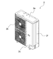
- the external appearance perspective view of the outdoor unit seen from the front side.
- FIG. 1 is a configuration diagram of an air conditioner according to an embodiment of the present invention.
- an outdoor unit 2 as a heat source side device and an indoor unit 4 as a usage side device are connected by a refrigerant pipe, and a refrigerant circuit 10 for performing a vapor compression refrigeration cycle is formed.
- the outdoor unit 2 accommodates a compressor 21, a four-way switching valve 22, an outdoor heat exchanger 23, an expansion valve 24, an accumulator 25, an outdoor fan 26, a hot gas bypass valve 27, a capillary tube 28, and an electromagnetic induction heating unit 6.
- the indoor unit 4 houses an indoor heat exchanger 41 and an indoor fan 42.
- the refrigerant circuit 10 includes a discharge pipe 10a, a gas pipe 10b, a liquid pipe 10c, an outdoor liquid pipe 10d, an outdoor gas pipe 10e, an accumulator pipe 10f, a suction pipe 10g, and a hot gas bypass 10h.
- the discharge pipe 10 a connects the compressor 21 and the four-way switching valve 22.
- the gas pipe 10 b connects the four-way switching valve 22 and the indoor heat exchanger 41.
- the liquid pipe 10 c connects the indoor heat exchanger 41 and the expansion valve 24.
- the outdoor liquid pipe 10 d connects the expansion valve 24 and the outdoor heat exchanger 23.
- the outdoor gas pipe 10 e connects the outdoor heat exchanger 23 and the four-way switching valve 22.
- the accumulator pipe 10 f connects the four-way switching valve 22 and the accumulator 25.
- the electromagnetic induction heating unit 6 is attached to a part of the accumulator tube 10f.
- the periphery of the copper tube is covered with a stainless steel tube.
- the portion other than the stainless steel tube is a copper tube.
- the suction pipe 10g connects the accumulator 25 and the suction side of the compressor 21.
- the hot gas bypass 10h connects a branch point A1 provided in the middle of the discharge pipe 10a and a branch point D1 provided in the middle of the outdoor liquid pipe 10d.
- the hot gas bypass valve 27 is arranged in the middle of the hot gas bypass 10h.
- the controller 11 opens and closes the hot gas bypass valve 27 to switch the hot gas bypass 10h between a state where the refrigerant flow is allowed and a state where the hot gas bypass 10h is not allowed.
- a capillary tube 28 for reducing the cross-sectional area of the refrigerant flow passage is provided downstream of the hot gas bypass valve 27, and the refrigerant flowing through the outdoor heat exchanger 23 and the hot gas bypass 10h during the defrosting operation.
- the ratio of the refrigerant that circulates is kept constant.
- the four-way switching valve 22 can switch between a cooling operation cycle and a heating operation cycle.
- the connection state for performing the heating operation is indicated by a solid line
- the connection state for performing the cooling operation is indicated by a dotted line.
- the indoor heat exchanger 41 functions as a condenser
- the outdoor heat exchanger 23 functions as an evaporator.
- the outdoor heat exchanger 23 functions as a condenser
- the indoor heat exchanger 41 functions as an evaporator.
- FIG. 2 is an external perspective view of the outdoor unit viewed from the front side.
- FIG. 2 is an external perspective view of the outdoor unit viewed from the front side.
- the outer shell of the outdoor unit 2 is a top plate 2a, a bottom plate (invisible) facing the top plate 2a, a front panel 2c, a fan guard 2k, a right side panel 2f, and a left side panel facing the right side panel 2f.
- a substantially rectangular parallelepiped shape is formed by the rear panel (invisible) facing the front panel 2c and the fan guard 2k.
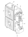
- FIG. 3 is a perspective view of the outdoor unit from which the front panel, the right side panel, and the back panel are removed.
- the outdoor unit 2 is divided into a blower room and a machine room by a partition plate 2h.
- An outdoor heat exchanger 23 and an outdoor fan are arranged in the blower room, and an electromagnetic induction heating unit 6, a compressor 21, and an accumulator 25 are arranged in the machine room.
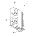
- FIG. 4 is a perspective view of the outdoor unit from which members other than the bottom plate, the outdoor heat exchanger, and the outdoor fan are removed.
- the outdoor heat exchanger 23 is a fin-and-tube heat exchanger formed in an L shape.
- Two outdoor fans 26 are arranged between the fan guard 2k (see FIG. 3) and the outdoor heat exchanger 23 so as to be adjacent to each other in the vertical direction via a support base. As the outdoor fan 26 rotates, outdoor air is sucked from the vents of the left side panel and the rear panel, passes between the fins of the outdoor heat exchanger 23, and is blown out from the fan guard 2k.
- FIG. 5 is a plan view of the outdoor unit from which members other than the bottom plate and the machine room are removed.
- the outdoor heat exchanger 23 is drawn by a two-dot chain line so that the position of the outdoor heat exchanger 23 can be understood.
- the hot gas bypass 10h is arranged on the bottom plate 2b, extends from the machine room side where the compressor 21 is located to the blower room side, goes around the blower room side bottom, and returns to the machine room side. About half of the total length of the hot gas bypass 10 h is located below the outdoor heat exchanger 23.
- FIG. 6 is a cross-sectional view of the electromagnetic induction heating unit.
- the electromagnetic induction heating unit 6 is arranged so as to cover the heated portion of the accumulator tube 10f from the radially outer side, and heats the heated portion by electromagnetic induction heating.
- the heated portion of the accumulator tube 10f has a double tube structure with an inner copper tube and an outer stainless steel tube 100f.
- the stainless steel material used for the stainless steel pipe 100f is a ferritic stainless steel containing 16 to 18% chromium, or a precipitation hardening system containing 3 to 5% nickel, 15 to 17.5% chromium, and 3 to 5% copper. Stainless steel is selected.
- the electromagnetic induction heating unit 6 is first positioned on the accumulator tube 10 f, then the vicinity of the upper end is fixed by the first hex nut 61, and finally the vicinity of the lower end is fixed by the second hex nut 66.
- the coil 68 is spirally wound around the outside of the bobbin main body 65.
- the coil 68 is accommodated inside the ferrite case 71.
- the ferrite case 71 further accommodates a first ferrite part 69 and a second ferrite part 70.
- the first ferrite portion 69 is formed of ferrite having a high magnetic permeability, and forms a path of magnetic flux together with the stainless steel tube 100f when a current is passed through the coil 68.
- the first ferrite part 69 is located on both ends of the ferrite case 71.
- the second ferrite portion 70 is different in position and shape from the first ferrite portion 69, but its function is the same as that of the first ferrite portion 69, and is disposed in the vicinity of the outside of the bobbin main body 65 in the accommodating portion of the ferrite case 71.
- the air conditioner 1 can be switched to either the cooling operation or the heating operation by the four-way switching valve 22.
- the four-way switching valve 22 is set to the state indicated by the dotted line in FIG.
- the compressor 21 is operated in this state, the refrigerant circuit 10 performs a vapor compression refrigeration cycle in which the outdoor heat exchanger 23 serves as a condenser and the indoor heat exchanger 41 serves as an evaporator.
- the high-pressure refrigerant discharged from the compressor 21 is condensed by exchanging heat with outdoor air in the outdoor heat exchanger 23.
- the refrigerant that has passed through the outdoor heat exchanger 23 is decompressed when passing through the expansion valve 24, and then evaporates by exchanging heat with indoor air in the indoor heat exchanger 41. Then, the air whose temperature has decreased due to heat exchange with the refrigerant is blown out into the air conditioning target space.
- the refrigerant that has passed through the indoor heat exchanger 41 is sucked into the compressor 21 and compressed.
- the four-way switching valve 22 is set to the state shown by the solid line in FIG.
- the compressor 21 When the compressor 21 is operated in this state, the refrigerant circuit 10 performs a vapor compression refrigeration cycle in which the outdoor heat exchanger 23 serves as an evaporator and the indoor heat exchanger 41 serves as a condenser.
- the high-pressure refrigerant discharged from the compressor 21 is condensed by exchanging heat with indoor air in the indoor heat exchanger 41. Then, the air whose temperature has increased due to heat exchange with the refrigerant is blown out into the air-conditioning target space.
- the condensed refrigerant is decompressed when passing through the expansion valve 24, and then evaporates by exchanging heat with outdoor air in the outdoor heat exchanger 23.
- the refrigerant that has passed through the outdoor heat exchanger 23 is sucked into the compressor 21 and compressed.
- the electromagnetic induction heating unit 6 heats the accumulator pipe 10f, so that the compressor 21 can compress the warmed refrigerant.
- the temperature of the gas refrigerant discharged from the compressor 21 rises, and the lack of heating capacity at startup is compensated.
- defrosting operation When the heating operation is performed, moisture contained in the air condenses on the surface of the outdoor heat exchanger 23, forms frost or freezes, covers the surface of the outdoor heat exchanger, and reduces the heat exchange performance. For this reason, defrosting operation is performed in order to melt frost or ice adhering to the outdoor heat exchanger 23. The defrosting operation is performed in the same cycle as the cooling operation.
- the high-pressure refrigerant discharged from the compressor 21 is condensed by exchanging heat with outdoor air in the outdoor heat exchanger 23.
- the frost or ice covering the outdoor heat exchanger 23 is melted by the heat radiation from the refrigerant.
- the refrigerant which has dissipated heat and is condensed is reduced in pressure when passing through the expansion valve 24, and then is evaporated by exchanging heat with indoor air in the indoor heat exchanger 41. At this time, the indoor fan 42 is stopped. This is because when the indoor fan 42 is operated, the cooled air is blown into the air-conditioning target space and the comfort is impaired.
- the refrigerant that has passed through the indoor heat exchanger 41 is sucked into the compressor 21 and compressed.
- the electromagnetic induction heating unit 6 heats the accumulator tube 10f, so that the compressor 21 can compress the warmed refrigerant.
- the temperature of the gas refrigerant discharged from the compressor 21 increases, and the defrosting capability is improved.
- the high-pressure refrigerant discharged from the compressor 21 is also passed through the hot gas bypass 10h. Even when frost or ice grows on the bottom plate 2b of the outdoor unit 2, the ice is melted by heat radiation from the refrigerant passing through the hot gas bypass 10h. The water generated at that time is drained from the drain ports 86a to 86e.
- the fan defrosting operation is an operation in which the outdoor fan 26 is rotated for a predetermined time after the defrosting operation is completed, and the frost attached to the outdoor fan 26 main body and its peripheral members is melted by the air that has passed through the outdoor heat exchanger 23.
- FIG. 7 is a time chart before and after the fan defrosting operation of the air conditioner.
- the fan defrosting operation is performed for a predetermined time with the operation frequency of the compressor 21 being set to a specific frequency lower than that during the defrosting operation while maintaining the refrigeration cycle during the defrosting operation.
- the predetermined time is set to a time length suitable for the climatic conditions of the place where the air conditioner is installed. Specifically, the predetermined time can be set in three stages of 60 seconds, 80 seconds and 100 seconds. It is set via a setting button at the time of installation. As a result, a state in which frost remains on the outdoor fan 26 main body and its peripheral members after the fan defrosting operation control is avoided.
- the predetermined time can be set at times other than when the air conditioner 1 is installed, and whether or not to set the fan defrosting operation to be performed can be set at times other than when the air conditioner 1 is installed.
- the outdoor fan 26 rotates at a relatively low rotational speed.
- the rotation speed of the outdoor fan 26 can be switched within a range of 1 to 8 steps (including stoppage), and the third step 3 from the lowest is selected during the fan defrosting operation.
- the outdoor fan 26 is stopped during the defrosting operation performed before the fan defrosting operation.
- the fan defrosting operation is not necessarily executed, but is executed when a predetermined condition is satisfied immediately before the start of the defrosting operation.
- the defrosting operation is executed when the outside air temperature and the outdoor heat exchanger temperature are equal to or lower than preset temperatures after a certain time has elapsed since the previous defrosting operation.
- the process is executed after the defrosting operation is completed.
- the outside air temperature is measured via an outside air temperature sensor 102 attached to the outdoor unit 2.
- the fan guard 2k is frosted as well as the outdoor heat exchanger 23.
- the outdoor fan 26 is a propeller fan, if it is a type with a bell mouth around the propeller, the bell mass is also frosted. If the outdoor fan 26 is a turbo fan, the fan blades are also frosted. In such a state, even if the defrosting operation is completed, only the frost of the outdoor heat exchanger 23 is melted, and the frost attached to the fan guard 2k around the outdoor fan 26 is not melted.
- the outdoor fan 26 since the outdoor fan 26 is operated by the fan defrosting operation, the air heated by the outdoor heat exchanger 23 is sent to peripheral members of the outdoor fan 26 body such as the outdoor fan 26 body and the fan guard 2k. Therefore, the frost attached to the fan guard 2k is also warmed and melted.
- the compressor 21 since the compressor 21 is operating, the temperature of the refrigerant flowing into the outdoor heat exchanger 23 is maintained high, and the defrosting capability is increased. Furthermore, since the electromagnetic induction heating unit 6 heats the accumulator tube 10f, the compressor 21 can compress the warmed refrigerant, so that the temperature of the gas refrigerant discharged from the compressor 21 rises and outdoor heat exchange is performed. The temperature of the refrigerant flowing into the vessel 23 is further increased, and the defrosting capability is further increased. As a result, the time required to melt the frost is shortened. (Equal pressure operation) After the fan defrosting operation is completed, a pressure equalizing operation is performed in which the compressor 21 is stopped and the outdoor fan 26 is operated. In addition, when the fan defrosting operation is not performed, the pressure equalizing operation is performed after the defrosting operation is completed.
- Step 6 is selected as the rotational speed of the outdoor fan 26 during the pressure equalizing operation, which is higher than that during the fan defrosting operation.
- the purpose of the pressure equalization operation is to eliminate the high / low pressure difference in the refrigerant circuit 10 or to a predetermined value or less. In this embodiment, until the end of the fan defrosting operation, 80 seconds elapses, or The pressure equalizing operation is performed until the high-low pressure difference in the refrigerant circuit 10 becomes 0.49 MPa or less. If the refrigeration cycle is switched to the heating operation without performing the pressure equalization operation, devices such as the four-way switching valve 22 are adversely affected by the impact due to the high / low pressure difference in the refrigerant circuit 10.
- the operating frequency of the compressor 21 before the pressure equalizing operation is low. For that reason, in the fan defrosting operation before the pressure equalizing operation, the operation frequency of the compressor 21 is set to a specific frequency lower than that during the defrosting operation.
- the controller 11 defrosts the fan for operating the outdoor fan 26 for a preset time after the defrost operation is completed. Perform operation control. As a result, the frost attached to the outdoor fan 26 main body and its peripheral members (for example, the bell mouth and the fan guard) is melted.
- the control unit 11 operates the compressor 21 at a specific operation frequency lower than that during the defrosting operation. As a result, the temperature of the refrigerant flowing into the outdoor heat exchanger 23 is maintained high, so that the temperature drop of the warm air toward the outdoor fan 26 main body and its peripheral members is suppressed.
- control unit 11 stops the compressor 21 before switching to the heating operation, and performs a pressure equalizing operation that reduces the high-low pressure difference in the refrigerant circuit 10. As a result, switching to heating operation is performed safely.
- an air conditioner for a cold region and a high humidity region.
- Air Conditioner Electromagnetic Induction Heating Unit (Refrigerant Heating Device) DESCRIPTION OF SYMBOLS 10 Refrigerant circuit 11 Control part 21 Compressor 22 Four-way switching valve 23 Outdoor heat exchanger 24 Expansion valve (pressure reduction mechanism) 26 outdoor fan 42 indoor heat exchanger 102 outdoor temperature sensor
Landscapes
- Engineering & Computer Science (AREA)
- Mechanical Engineering (AREA)
- General Engineering & Computer Science (AREA)
- Chemical & Material Sciences (AREA)
- Combustion & Propulsion (AREA)
- Physics & Mathematics (AREA)
- Thermal Sciences (AREA)
- Air Conditioning Control Device (AREA)
Abstract
Description
しかしながら、特許文献1に開示されているような空気調和装置では、室外熱交換器に付着した霜を融かすことはできるが、室外ファン本体、室外ファン周辺のベルマウスおよびファンガードなどに付着した霜までを融かすことはできなかった。
所定の条件下では、除霜運転終了後であっても室外ファン本体およびその周辺部材(例えば、ベルマウス及びファンガード)に付着した霜は融解しない。しかし、この空気調和装置では、室外ファンが回転することによって、温度上昇した室外熱交換器を通過する空気が温風となって室外ファン本体およびその周辺部材に当たるので、そこに付着している霜が融解する。
この空気調和装置では、ファン除霜運転制御時に冷媒加熱装置が稼動することによって、室外熱交換器に流入する冷媒温度が高く維持されるので、室外ファン本体およびその周辺部材に向う温風の温度低下が抑制される。その結果、室外ファン本体およびその周辺部材を除霜する能力が向上する。
第2発明に係る空気調和装置では、制御部が外気温度に応じてファン除霜運転制御を実行するか否かを判断するので、無駄なファン除霜運転が防止される。
第3発明に係る空気調和装置では、ファン除霜運転制御時に圧縮機が稼動することによって、室外熱交換器に流入する冷媒温度が高く維持されるので、室外ファン本体およびその周辺部材に向う温風の温度低下が抑制される。その結果、室外ファン本体およびその周辺部材を除霜する能力が向上する。
第4発明に係る空気調和装置では、ファン除霜運転後の動作に備えた特定の運転周波数が設定されるので、ファン除霜運転後の動作が円滑に行われるようになる。
第6発明に係る空気調和装置では、ファン除霜運転制御時に圧縮機を稼動しているので、暖房運転前に圧縮機停止が行われることによって、冷媒回路内が均圧化され暖房運転への切り替えが安全に行われる。
第7発明に係る空気調和装置では、室外ファン本体およびその周辺部材を除霜する能力が向上する。
第8発明に係る空気調和装置では、配管が直接加熱されるので、冷媒の温度上昇速度が高まる。
<空気調和装置>
図1は、本発明の一実施形態に係る空気調和装置の構成図である。図1において、空気調和装置1では、熱源側装置としての室外機2と、利用側装置としての室内機4とが冷媒配管によって接続され、蒸気圧縮式冷凍サイクルを行う冷媒回路10が形成されている。
室外機2は、圧縮機21、四路切換弁22、室外熱交換器23、膨張弁24、アキュームレータ25、室外ファン26、ホットガスバイパス弁27、キャピラリチューブ28および電磁誘導加熱ユニット6を収容している。室内機4は、室内熱交換器41および室内ファン42を収容している。
吐出管10aは、圧縮機21と四路切換弁22とを接続している。ガス管10bは、四路切換弁22と室内熱交換器41とを接続している。液管10cは、室内熱交換器41と膨張弁24とを接続している。室外側液管10dは、膨張弁24と室外熱交換器23とを接続している。室外側ガス管10eは、室外熱交換器23と四路切換弁22とを接続している。
アキューム管10fは、四路切換弁22とアキュームレータ25とを接続している。電磁誘導加熱ユニット6は、アキューム管10fの一部分に取り付けられている。アキューム管10fのうち、少なくとも電磁誘導加熱ユニット6によって覆われている被加熱部分では、銅管の周囲がステンレス鋼管で覆われている。冷媒回路10を構成する配管のうち、そのステンレス鋼管以外の部分は銅管である。
ホットガスバイパス10hは、途中にホットガスバイパス弁27が配置されている。制御部11は、ホットガスバイパス弁27を開閉して、ホットガスバイパス10hを冷媒の流通を許容する状態と許容しない状態とに切換える。また、ホットガスバイパス弁27の下流側には、冷媒の流通路の断面積を減じるキャピラリチューブ28が設けられており、除霜運転時、室外熱交換器23を流通する冷媒とホットガスバイパス10hを流通する冷媒との割合が一定に保たれている。
四路切換弁22は、冷房運転サイクルと暖房運転サイクルとを切り替えることができる。図1では、暖房運転を行うための接続状態を実線で示し、冷房運転を行うための接続状態を点線で示している。暖房運転時、室内熱交換器41は凝縮器として、室外熱交換器23は蒸発器として機能する。冷房運転時、室外熱交換器23は凝縮器として、室内熱交換器41は蒸発器として機能する。
制御部11は、室外制御部11aと室内制御部11bとを有している。室外制御部11aと室内制御部11bとは通信線11cによって接続されている。そして、室外制御部11aは室外機2内に配置される機器を制御し、室内制御部11bは室内機4内に配置されている機器を制御する。
(室外機の外観)
図2は正面側から視た室外機の外観斜視図である。図2において、室外機2の外殻は、天板2a、天板2aと対向する底板(不可視)、フロントパネル2c、ファンガード2k、右側面パネル2f、右側面パネル2fと対向する左側面パネル(不可視)、フロントパネル2c及びファンガード2kと対向する背面パネル(不可視)によって略直方体形状に形成されている。
図3は、フロントパネル、右側面パネルおよび背面パネルを取り除いた室外機の斜視図である。図3において、室外機2は、仕切り板2hによって送風機室と機械室とに区分されている。送風機室には室外熱交換器23及び室外ファン(不可視)が配置され、機械室には電磁誘導加熱ユニット6、圧縮機21、及びアキュームレータ25が配置されている。
図4は、底板、室外熱交換器および室外ファン以外の部材を取り除いた室外機の斜視図である。図4において、室外熱交換器23は、L字形状に成形されているフィン・アンド・チューブ式熱交換器である。そして、2台の室外ファン26が、ファンガード2k(図3参照)と室外熱交換器23との間に、支持台を介して鉛直方向に隣接するように配置されている。室外ファン26が回転することによって、室外空気が左側面パネル及び背面パネルの通気口から吸い込まれ、室外熱交換器23のフィン間を通過し、ファンガード2kから吹き出される。
図5は、底板および機械室以外の部材を取り除いた室外機の平面図である。なお、図5には、室外熱交換器23の位置が分かるように室外熱交換器23が2点鎖線で描かれている。ホットガスバイパス10hは底板2b上に配置されており、圧縮機21が位置する機械室側から送風機室側に延び、送風機室側底部を一周して機械室側に戻る。ホットガスバイパス10hの全長の約半分は、室外熱交換器23の下方に位置する。また、底板2bのうちの室外熱交換器23の下方に位置する部分には、底板2bを板厚方向に貫通する排水口86a~86eが形成されている。
(電磁誘導加熱ユニット)
図6は、電磁誘導加熱ユニットの断面図である。図6において、電磁誘導加熱ユニット6は、アキューム管10fのうち被加熱部分を径方向外側から覆うように配置されており、電磁誘導加熱によって被加熱部分を加熱する。アキューム管10fの被加熱部分は、内側の銅管と外側のステンレス鋼管100fとによって二重管構造となっている。ステンレス鋼管100fに使用されるステンレス材料は、クロムを16~18%含むフェライト系ステンレス、或はニッケルを3~5%、クロムを15~17.5%、銅を3~5%含む析出硬化系ステンレスが選択される。
コイル68は、ボビン本体65の外側に螺旋状に巻き付けられている。コイル68は、フェライトケース71の内側に収容されている。フェライトケース71は、第1フェライト部69及び第2フェライト部70をさらに収容している。
第1フェライト部69は、透磁率の高いフェライトによって成形されており、コイル68に電流を流した際に、ステンレス鋼管100fと共に磁束の通り道を形成する。第1フェライト部69は、フェライトケース71の両端側に位置する。
第2フェライト部70は、位置および形状は第1フェライト部69と異なるが、その機能は第1フェライト部69と同様であり、フェライトケース71の収容部のうちボビン本体65の外側近傍に配置される。
空気調和装置1は、四路切換弁22によって、冷房運転および暖房運転のいずれか一方に切り換えることが可能である。
(冷房運転)
冷房運転では、四路切換弁22が、図1の点線で示された状態に設定される。この状態で圧縮機21が運転されたとき、冷媒回路10では、室外熱交換器23が凝縮器となり、室内熱交換器41が蒸発器となる蒸気圧縮冷凍サイクルが行われる。
圧縮機21から吐出された高圧の冷媒は、室外熱交換器23で室外空気と熱交換して凝縮する。室外熱交換器23を通過した冷媒は、膨張弁24を通過する際に減圧され、その後に室内熱交換器41で室内空気と熱交換して蒸発する。そして、冷媒との熱交換によって温度低下した空気は、空調対象空間に吹き出される。室内熱交換器41を通過した冷媒は、圧縮機21へ吸入されて圧縮される。
暖房運転では、四路切換弁22が、図1の実線で示された状態に設定される。この状態で圧縮機21が運転されたとき、冷媒回路10では、室外熱交換器23が蒸発器となり、室内熱交換器41が凝縮器となる蒸気圧縮冷凍サイクルが行われる。
圧縮機21から吐出された高圧の冷媒は、室内熱交換器41で室内空気と熱交換して凝縮する。そして、冷媒との熱交換によって温度上昇した空気は、空調対象空間に吹き出される。凝縮した冷媒は、膨張弁24を通過する際に減圧された後、室外熱交換器23で室外空気と熱交換して蒸発する。室外熱交換器23を通過した冷媒は、圧縮機21へ吸入されて圧縮される。
暖房運転の起動時、特に、圧縮機21が十分に暖まっていないとき、電磁誘導加熱ユニット6がアキューム管10fを加熱することによって、圧縮機21は暖められた冷媒を圧縮することができる。その結果、圧縮機21から吐出するガス冷媒の温度が上昇し、起動時の暖房能力不足が補われる。
暖房運転がおこなわれたとき、空気中に含まれる水分が室外熱交換器23の表面で結露し、霜となり或は氷結して室外熱交換器の表面を覆い、熱交換性能を低下させる。このため、室外熱交換器23に付着した霜、或は氷を融かすために除霜運転が行われる。除霜運転は、冷房運転と同じサイクルで行われる。
圧縮機21から吐出された高圧の冷媒は、室外熱交換器23で室外空気と熱交換して凝縮する。その冷媒からの放熱によって、室外熱交換器23を覆う霜、或は氷が融かされる。放熱して凝縮した冷媒は、膨張弁24を通過する際に減圧され、その後に室内熱交換器41で室内空気と熱交換して蒸発する。このとき、室内ファン42は停止している。なぜなら、室内ファン42が稼動すると、空調対象空間に冷やされた空気が吹き出されて快適性を損なうからである。室内熱交換器41を通過した冷媒は、圧縮機21へ吸入されて圧縮される。
また、除霜運転時、ホットガスバイパス10hにも圧縮機21から吐出された高圧の冷媒が流される。室外機2の底板2b上に霜、或は氷が成長している場合でも、その氷はホットガスバイパス10hを通る冷媒からの放熱によって融かされる。そのとき発生した水は、排水口86a~86eから排水される。また、排水口86a~86eもホットガスバイパス10hによって加熱されるので、排水口86a~86eが凍結によって塞がれることは防止される。
<空気調和装置のその他の動作>
(ファン除霜運転)
ファン除霜運転とは、除霜運転終了後に室外ファン26を所定時間回転させ、室外熱交換器23を通過した空気で室外ファン26本体およびその周辺部材に付着した霜を融解させる運転である。以下、図面を参照しながら説明する。
ファン除霜運転は、必ず実行されるものではなく、除霜運転開始直前に所定条件が成立している場合に実行される。通常、除霜運転は、先の除霜運転から一定時間経過後で、外気温度および室外熱交換器温度が予め設定された温度以下になったときに実行されるが、ファン除霜運転は、除霜運転が開始される直前の外気温度が-5℃~5℃の範囲内のとき、除霜運転終了後に実行される。なお、外気温度は、室外機2に取り付けられた外気温度センサ102を介して測定されている。
(均圧運転)
ファン除霜運転が終了した後、圧縮機21を停止させて室外ファン26を稼動させる均圧運転が行われる。なお、ファン除霜運転が実行されていない場合は、除霜運転が終了した後に均圧運転が実行される。
冷媒回路10内の高低圧差が素早く所定値(0.49MPa)以下となるためには、均圧運転前の圧縮機21の運転周波数が低いことが好ましい。その理由から、均圧運転前のファン除霜運転では、圧縮機21の運転周波数が除霜運転時よりも低い特定の周波数に設定されている。
(1)
空気調和装置1では、制御部11は、暖房運転開始直前の外気温度が-5℃~5℃のとき、除霜運転終了後に室外ファン26を予め設定された時間だけ稼動させるためのファン除霜運転制御を行う。その結果、室外ファン26本体およびその周辺部材(例えば、ベルマウス及びファンガード)に付着した霜が融解する。
(2)
ファン除霜運転時、制御部11は、圧縮機21を除霜運転時よりも低い特定の運転周波数で稼動させる。その結果、室外熱交換器23に流入する冷媒温度が高く維持されるので、室外ファン26本体およびその周辺部材に向う温風の温度低下が抑制される。
制御部11は、ファン除霜運転制御終了後、暖房運転への切り替え前に圧縮機21を停止させて、冷媒回路10内の高低圧差を減縮する均圧運転を行う。その結果、暖房運転への切り替えが安全に行われる。
6 電磁誘導加熱ユニット(冷媒加熱装置)
10 冷媒回路
11 制御部
21 圧縮機
22 四路切換弁
23 室外熱交換器
24 膨張弁(減圧機構)
26 室外ファン
42 室内熱交換器
102 外気温度センサ
Claims (8)
- 暖房運転時に、圧縮機(21)、室内熱交換器(42)、減圧機構(24)、及び室外熱交換器(23)の順で冷媒が循環する冷媒回路(10)と、
前記冷媒回路(10)に接続され、前記圧縮機(21)から吐出された前記冷媒の流れ方向を切り替える切換弁(22)と、
室外ファン(26)と、
除霜運転時に、前記室外ファン(26)を停止させ且つ前記圧縮機(21)から吐出された冷媒を前記切換弁(22)によって前記室外熱交換器(23)に向わせる除霜運転制御を行なう制御部(11)と、
を備え、
前記制御部(11)は、所定条件成立時、前記除霜運転終了後に前記圧縮機(21)から吐出された冷媒を前記室外熱交換器(23)に向わせる運転のまま、前記室外ファン(26)を所定時間回転させるファン除霜運転制御を行う、
空気調和装置(1)。 - 外気温度を測定する外気温度センサ(102)をさらに備え、
前記制御部(11)は、前記外気温度センサ(102)を介して検知した外気温度が所定範囲内にあるとき、前記ファン除霜運転制御を実行する、
請求項1に記載の空気調和装置(1)。 - 前記制御部(11)は、前記ファン除霜運転制御時に前記圧縮機(21)を稼動させる、
請求項1に記載の空気調和装置(1)。 - 前記制御部(11)は、前記ファン除霜運転制御時に前記圧縮機(21)を前記除霜運転時よりも低い特定の運転周波数で稼動させる、
請求項1に記載の空気調和装置(1)。 - 前記所定時間は、少なくとも据付場所での初期設定時に選択可能である、
請求項1に記載の空気調和装置(1)。 - 前記制御部(11)は、前記ファン除霜運転制御終了後、前記暖房運転への切り替え前に前記圧縮機(21)を停止させる、
請求項3又は請求項4に記載の空気調和装置(1)。 - 前記冷媒回路(10)を流れる前記冷媒を加熱する冷媒加熱装置(6)をさらに備え、
前記制御部(11)は、前記ファン除霜運転制御時に前記冷媒加熱装置(6)を稼動させる、
請求項3又は請求項4に記載の空気調和装置(1)。 - 前記冷媒加熱装置(6)が、電磁誘導ヒータである、
請求項7に記載の空気調和装置(1)。
Priority Applications (5)
| Application Number | Priority Date | Filing Date | Title |
|---|---|---|---|
| EP09825923.7A EP2357434B1 (en) | 2008-11-17 | 2009-11-13 | Air conditioning device |
| US13/128,500 US8707719B2 (en) | 2008-11-17 | 2009-11-13 | Air conditioner |
| AU2009315174A AU2009315174B2 (en) | 2008-11-17 | 2009-11-13 | Air conditioner |
| CN2009801424145A CN102197269B (zh) | 2008-11-17 | 2009-11-13 | 空调装置 |
| ES09825923.7T ES2687260T3 (es) | 2008-11-17 | 2009-11-13 | Procedimiento y sistema de carga rápida |
Applications Claiming Priority (2)
| Application Number | Priority Date | Filing Date | Title |
|---|---|---|---|
| JP2008-293141 | 2008-11-17 | ||
| JP2008293141A JP4666061B2 (ja) | 2008-11-17 | 2008-11-17 | 空気調和装置 |
Publications (1)
| Publication Number | Publication Date |
|---|---|
| WO2010055670A1 true WO2010055670A1 (ja) | 2010-05-20 |
Family
ID=42169815
Family Applications (1)
| Application Number | Title | Priority Date | Filing Date |
|---|---|---|---|
| PCT/JP2009/006073 Ceased WO2010055670A1 (ja) | 2008-11-17 | 2009-11-13 | 空気調和装置 |
Country Status (8)
| Country | Link |
|---|---|
| US (1) | US8707719B2 (ja) |
| EP (1) | EP2357434B1 (ja) |
| JP (1) | JP4666061B2 (ja) |
| KR (1) | KR20110095361A (ja) |
| CN (1) | CN102197269B (ja) |
| AU (1) | AU2009315174B2 (ja) |
| ES (1) | ES2687260T3 (ja) |
| WO (1) | WO2010055670A1 (ja) |
Cited By (1)
| Publication number | Priority date | Publication date | Assignee | Title |
|---|---|---|---|---|
| CN109654608A (zh) * | 2019-02-18 | 2019-04-19 | 格力电器(杭州)有限公司 | 换热器的化霜结构及空调器 |
Families Citing this family (24)
| Publication number | Priority date | Publication date | Assignee | Title |
|---|---|---|---|---|
| WO2010106807A1 (ja) * | 2009-03-19 | 2010-09-23 | ダイキン工業株式会社 | 空気調和装置 |
| EP2757327B1 (en) * | 2011-09-13 | 2016-08-17 | Mitsubishi Electric Corporation | Refrigeration and air-conditioning device |
| US9239183B2 (en) | 2012-05-03 | 2016-01-19 | Carrier Corporation | Method for reducing transient defrost noise on an outdoor split system heat pump |
| CN103162384B (zh) * | 2013-03-04 | 2016-01-13 | 约克(无锡)空调冷冻设备有限公司 | 热泵运行的风机控制方法 |
| JP6225548B2 (ja) | 2013-08-08 | 2017-11-08 | 株式会社富士通ゼネラル | 空気調和装置 |
| JP6119639B2 (ja) * | 2014-02-27 | 2017-04-26 | 株式会社富士通ゼネラル | 空気調和機 |
| JP6134290B2 (ja) * | 2014-04-24 | 2017-05-24 | 本田技研工業株式会社 | 車両用空調装置 |
| CN105371524B (zh) * | 2014-08-26 | 2018-03-20 | 青岛海尔空调器有限总公司 | 压缩式制冷制热空调系统及其室外机除霜方法 |
| CN104833060B (zh) | 2015-05-22 | 2017-10-31 | 广东美的暖通设备有限公司 | 空调器的除霜控制方法和除霜控制装置 |
| JP6528623B2 (ja) * | 2015-09-24 | 2019-06-12 | 株式会社富士通ゼネラル | 空気調和装置 |
| KR101707617B1 (ko) | 2015-09-30 | 2017-02-21 | 삼성전자주식회사 | 공기 조화기 및 그 제어 방법 |
| JP6610287B2 (ja) * | 2016-01-26 | 2019-11-27 | 株式会社富士通ゼネラル | 空気調和装置 |
| JPWO2018029872A1 (ja) * | 2016-08-12 | 2019-06-06 | シャープ株式会社 | 空気調和機 |
| CN108302651B (zh) * | 2016-09-18 | 2020-09-04 | 苏州三星电子有限公司 | 一种多联机空调室外机系统及其除霜方法 |
| EP3531045A4 (en) * | 2016-10-20 | 2019-08-28 | GD Midea Heating & Ventilating Equipment Co., Ltd. | METHOD AND DEVICE FOR DEFROSTING AN AIR-CONDITIONING SYSTEM |
| CN107560217A (zh) * | 2017-09-07 | 2018-01-09 | 珠海格力电器股份有限公司 | 热泵系统及其控制方法 |
| JP6620800B2 (ja) * | 2017-10-30 | 2019-12-18 | ダイキン工業株式会社 | 空調装置 |
| JP6965736B2 (ja) * | 2017-12-27 | 2021-11-10 | 株式会社富士通ゼネラル | 空気調和機 |
| CN108800731A (zh) * | 2018-05-09 | 2018-11-13 | 青岛海尔股份有限公司 | 蒸发器组件、具有该组件的冰箱及冰箱化霜控制方法 |
| CN111189155A (zh) * | 2018-11-15 | 2020-05-22 | 杭州先途电子有限公司 | 空调控制方法、装置、控制器及空调 |
| CN113007791A (zh) * | 2019-12-20 | 2021-06-22 | 青岛海信日立空调系统有限公司 | 一种空调 |
| CN114076385B (zh) * | 2020-08-10 | 2023-12-26 | 海信空调有限公司 | 一种空调及空调室外机自动清洁方法 |
| WO2025210725A1 (ja) * | 2024-04-02 | 2025-10-09 | 三菱電機株式会社 | 空気調和機および空気調和機の制御方法 |
| CN118582862A (zh) * | 2024-06-27 | 2024-09-03 | 广东万和电气有限公司 | 一种热泵系统及热泵系统的控制方法 |
Citations (9)
| Publication number | Priority date | Publication date | Assignee | Title |
|---|---|---|---|---|
| JPS629066U (ja) * | 1985-07-01 | 1987-01-20 | ||
| JPH04356647A (ja) * | 1991-05-31 | 1992-12-10 | Toshiba Corp | 空気調和機の制御装置 |
| JPH04366341A (ja) | 1991-06-13 | 1992-12-18 | Daikin Ind Ltd | 空気調和装置 |
| JPH0743051A (ja) * | 1993-07-30 | 1995-02-10 | Toshiba Corp | 空気調和装置 |
| JP2002333183A (ja) * | 2001-05-08 | 2002-11-22 | Daikin Ind Ltd | 冷凍装置および冷凍装置のデータ書き込み方法 |
| JP2004233015A (ja) * | 2003-02-03 | 2004-08-19 | Hitachi Ltd | 空気調和機 |
| JP2007051825A (ja) * | 2005-08-18 | 2007-03-01 | Matsushita Electric Ind Co Ltd | 空気調和装置 |
| JP2007255736A (ja) * | 2006-03-20 | 2007-10-04 | Daikin Ind Ltd | 冷媒加熱装置および加熱制御方法 |
| JP2008116156A (ja) * | 2006-11-07 | 2008-05-22 | Matsushita Electric Ind Co Ltd | 空気調和装置 |
Family Cites Families (4)
| Publication number | Priority date | Publication date | Assignee | Title |
|---|---|---|---|---|
| KR20010089909A (ko) | 1998-12-07 | 2001-10-17 | 구자홍 | 공기조화기의 제상장치 및 제상방법 |
| KR20010001013A (ko) | 1999-06-01 | 2001-01-05 | 구자홍 | 공기조화기의 제상운전 방법 |
| US7856836B2 (en) * | 2005-07-26 | 2010-12-28 | Mitsubishi Electric Corporation | Refrigerating air conditioning system |
| US20080190131A1 (en) * | 2007-02-09 | 2008-08-14 | Lennox Manufacturing., Inc. A Corporation Of Delaware | Method and apparatus for removing ice from outdoor housing for an environmental conditioning unit |
-
2008
- 2008-11-17 JP JP2008293141A patent/JP4666061B2/ja active Active
-
2009
- 2009-11-13 ES ES09825923.7T patent/ES2687260T3/es active Active
- 2009-11-13 AU AU2009315174A patent/AU2009315174B2/en not_active Ceased
- 2009-11-13 EP EP09825923.7A patent/EP2357434B1/en active Active
- 2009-11-13 CN CN2009801424145A patent/CN102197269B/zh active Active
- 2009-11-13 US US13/128,500 patent/US8707719B2/en active Active
- 2009-11-13 WO PCT/JP2009/006073 patent/WO2010055670A1/ja not_active Ceased
- 2009-11-13 KR KR1020117013806A patent/KR20110095361A/ko not_active Ceased
Patent Citations (9)
| Publication number | Priority date | Publication date | Assignee | Title |
|---|---|---|---|---|
| JPS629066U (ja) * | 1985-07-01 | 1987-01-20 | ||
| JPH04356647A (ja) * | 1991-05-31 | 1992-12-10 | Toshiba Corp | 空気調和機の制御装置 |
| JPH04366341A (ja) | 1991-06-13 | 1992-12-18 | Daikin Ind Ltd | 空気調和装置 |
| JPH0743051A (ja) * | 1993-07-30 | 1995-02-10 | Toshiba Corp | 空気調和装置 |
| JP2002333183A (ja) * | 2001-05-08 | 2002-11-22 | Daikin Ind Ltd | 冷凍装置および冷凍装置のデータ書き込み方法 |
| JP2004233015A (ja) * | 2003-02-03 | 2004-08-19 | Hitachi Ltd | 空気調和機 |
| JP2007051825A (ja) * | 2005-08-18 | 2007-03-01 | Matsushita Electric Ind Co Ltd | 空気調和装置 |
| JP2007255736A (ja) * | 2006-03-20 | 2007-10-04 | Daikin Ind Ltd | 冷媒加熱装置および加熱制御方法 |
| JP2008116156A (ja) * | 2006-11-07 | 2008-05-22 | Matsushita Electric Ind Co Ltd | 空気調和装置 |
Non-Patent Citations (1)
| Title |
|---|
| See also references of EP2357434A4 |
Cited By (1)
| Publication number | Priority date | Publication date | Assignee | Title |
|---|---|---|---|---|
| CN109654608A (zh) * | 2019-02-18 | 2019-04-19 | 格力电器(杭州)有限公司 | 换热器的化霜结构及空调器 |
Also Published As
| Publication number | Publication date |
|---|---|
| JP2010121789A (ja) | 2010-06-03 |
| JP4666061B2 (ja) | 2011-04-06 |
| AU2009315174B2 (en) | 2012-12-13 |
| KR20110095361A (ko) | 2011-08-24 |
| EP2357434B1 (en) | 2018-08-22 |
| AU2009315174A1 (en) | 2011-06-23 |
| US20110209488A1 (en) | 2011-09-01 |
| CN102197269B (zh) | 2013-11-06 |
| ES2687260T3 (es) | 2018-10-24 |
| EP2357434A1 (en) | 2011-08-17 |
| US8707719B2 (en) | 2014-04-29 |
| CN102197269A (zh) | 2011-09-21 |
| EP2357434A4 (en) | 2014-05-21 |
Similar Documents
| Publication | Publication Date | Title |
|---|---|---|
| JP4666061B2 (ja) | 空気調和装置 | |
| JP5257462B2 (ja) | 空気調和装置 | |
| RU2486413C1 (ru) | Кондиционер | |
| JP5177281B2 (ja) | 空気調和装置 | |
| JP2011080733A (ja) | 空気調和機 | |
| JP5071371B2 (ja) | 空気調和装置 | |
| JP2010156490A (ja) | 空気調和装置 | |
| JP5315990B2 (ja) | 空気調和装置およびその制御方法 | |
| JP2010127602A (ja) | 冷凍装置 | |
| JP7065279B2 (ja) | 冷蔵庫 | |
| JP6272481B2 (ja) | 空気調和装置 | |
| JP2010223454A (ja) | 空気調和装置 | |
| JP2010112611A (ja) | 空気調和装置 | |
| KR20190046058A (ko) | 전기차용 공기조화장치 | |
| JP2017156023A (ja) | 空調装置 | |
| JP2626158B2 (ja) | 空気調和機の運転制御装置 | |
| JP2014032009A (ja) | 空気調和機 |
Legal Events
| Date | Code | Title | Description |
|---|---|---|---|
| WWE | Wipo information: entry into national phase |
Ref document number: 200980142414.5 Country of ref document: CN |
|
| 121 | Ep: the epo has been informed by wipo that ep was designated in this application |
Ref document number: 09825923 Country of ref document: EP Kind code of ref document: A1 |
|
| WWE | Wipo information: entry into national phase |
Ref document number: 13128500 Country of ref document: US |
|
| NENP | Non-entry into the national phase |
Ref country code: DE |
|
| WWE | Wipo information: entry into national phase |
Ref document number: 2009825923 Country of ref document: EP |
|
| ENP | Entry into the national phase |
Ref document number: 20117013806 Country of ref document: KR Kind code of ref document: A |
|
| ENP | Entry into the national phase |
Ref document number: 2009315174 Country of ref document: AU Date of ref document: 20091113 Kind code of ref document: A |