WO2010058834A1 - 粒子状物質浄化材料、粒子状物質浄化材料を用いた粒子状物質浄化用フィルタ触媒及び粒子状物質浄化用フィルタ触媒の再生方法 - Google Patents
粒子状物質浄化材料、粒子状物質浄化材料を用いた粒子状物質浄化用フィルタ触媒及び粒子状物質浄化用フィルタ触媒の再生方法 Download PDFInfo
- Publication number
- WO2010058834A1 WO2010058834A1 PCT/JP2009/069689 JP2009069689W WO2010058834A1 WO 2010058834 A1 WO2010058834 A1 WO 2010058834A1 JP 2009069689 W JP2009069689 W JP 2009069689W WO 2010058834 A1 WO2010058834 A1 WO 2010058834A1
- Authority
- WO
- WIPO (PCT)
- Prior art keywords
- particulate matter
- catalyst
- filter
- filter catalyst
- ceo
- Prior art date
- Legal status (The legal status is an assumption and is not a legal conclusion. Google has not performed a legal analysis and makes no representation as to the accuracy of the status listed.)
- Ceased
Links
Images




Classifications
-
- F—MECHANICAL ENGINEERING; LIGHTING; HEATING; WEAPONS; BLASTING
- F01—MACHINES OR ENGINES IN GENERAL; ENGINE PLANTS IN GENERAL; STEAM ENGINES
- F01N—GAS-FLOW SILENCERS OR EXHAUST APPARATUS FOR MACHINES OR ENGINES IN GENERAL; GAS-FLOW SILENCERS OR EXHAUST APPARATUS FOR INTERNAL-COMBUSTION ENGINES
- F01N3/00—Exhaust or silencing apparatus having means for purifying, rendering innocuous, or otherwise treating exhaust
- F01N3/02—Exhaust or silencing apparatus having means for purifying, rendering innocuous, or otherwise treating exhaust for cooling, or for removing solid constituents of, exhaust
- F01N3/021—Exhaust or silencing apparatus having means for purifying, rendering innocuous, or otherwise treating exhaust for cooling, or for removing solid constituents of, exhaust by means of filters
- F01N3/022—Exhaust or silencing apparatus having means for purifying, rendering innocuous, or otherwise treating exhaust for cooling, or for removing solid constituents of, exhaust by means of filters characterised by specially adapted filtering structure, e.g. honeycomb, mesh or fibrous
- F01N3/0222—Exhaust or silencing apparatus having means for purifying, rendering innocuous, or otherwise treating exhaust for cooling, or for removing solid constituents of, exhaust by means of filters characterised by specially adapted filtering structure, e.g. honeycomb, mesh or fibrous the structure being monolithic, e.g. honeycombs
-
- B—PERFORMING OPERATIONS; TRANSPORTING
- B01—PHYSICAL OR CHEMICAL PROCESSES OR APPARATUS IN GENERAL
- B01D—SEPARATION
- B01D46/00—Filters or filtering processes specially modified for separating dispersed particles from gases or vapours
- B01D46/24—Particle separators, e.g. dust precipitators, using rigid hollow filter bodies
- B01D46/2403—Particle separators, e.g. dust precipitators, using rigid hollow filter bodies characterised by the physical shape or structure of the filtering element
- B01D46/2418—Honeycomb filters
-
- B—PERFORMING OPERATIONS; TRANSPORTING
- B01—PHYSICAL OR CHEMICAL PROCESSES OR APPARATUS IN GENERAL
- B01D—SEPARATION
- B01D46/00—Filters or filtering processes specially modified for separating dispersed particles from gases or vapours
- B01D46/66—Regeneration of the filtering material or filter elements inside the filter
- B01D46/80—Chemical processes for the removal of the retained particles, e.g. by burning
- B01D46/82—Chemical processes for the removal of the retained particles, e.g. by burning with catalysts
-
- B—PERFORMING OPERATIONS; TRANSPORTING
- B01—PHYSICAL OR CHEMICAL PROCESSES OR APPARATUS IN GENERAL
- B01D—SEPARATION
- B01D53/00—Separation of gases or vapours; Recovering vapours of volatile solvents from gases; Chemical or biological purification of waste gases, e.g. engine exhaust gases, smoke, fumes, flue gases, aerosols
- B01D53/34—Chemical or biological purification of waste gases
- B01D53/92—Chemical or biological purification of waste gases of engine exhaust gases
- B01D53/94—Chemical or biological purification of waste gases of engine exhaust gases by catalytic processes
- B01D53/944—Simultaneously removing carbon monoxide, hydrocarbons or carbon making use of oxidation catalysts
-
- B—PERFORMING OPERATIONS; TRANSPORTING
- B01—PHYSICAL OR CHEMICAL PROCESSES OR APPARATUS IN GENERAL
- B01J—CHEMICAL OR PHYSICAL PROCESSES, e.g. CATALYSIS OR COLLOID CHEMISTRY; THEIR RELEVANT APPARATUS
- B01J23/00—Catalysts comprising metals or metal oxides or hydroxides, not provided for in group B01J21/00
- B01J23/002—Mixed oxides other than spinels, e.g. perovskite
-
- B—PERFORMING OPERATIONS; TRANSPORTING
- B01—PHYSICAL OR CHEMICAL PROCESSES OR APPARATUS IN GENERAL
- B01J—CHEMICAL OR PHYSICAL PROCESSES, e.g. CATALYSIS OR COLLOID CHEMISTRY; THEIR RELEVANT APPARATUS
- B01J23/00—Catalysts comprising metals or metal oxides or hydroxides, not provided for in group B01J21/00
- B01J23/10—Catalysts comprising metals or metal oxides or hydroxides, not provided for in group B01J21/00 of rare earths
-
- B—PERFORMING OPERATIONS; TRANSPORTING
- B01—PHYSICAL OR CHEMICAL PROCESSES OR APPARATUS IN GENERAL
- B01J—CHEMICAL OR PHYSICAL PROCESSES, e.g. CATALYSIS OR COLLOID CHEMISTRY; THEIR RELEVANT APPARATUS
- B01J23/00—Catalysts comprising metals or metal oxides or hydroxides, not provided for in group B01J21/00
- B01J23/16—Catalysts comprising metals or metal oxides or hydroxides, not provided for in group B01J21/00 of arsenic, antimony, bismuth, vanadium, niobium, tantalum, polonium, chromium, molybdenum, tungsten, manganese, technetium or rhenium
- B01J23/20—Vanadium, niobium or tantalum
-
- B—PERFORMING OPERATIONS; TRANSPORTING
- B01—PHYSICAL OR CHEMICAL PROCESSES OR APPARATUS IN GENERAL
- B01J—CHEMICAL OR PHYSICAL PROCESSES, e.g. CATALYSIS OR COLLOID CHEMISTRY; THEIR RELEVANT APPARATUS
- B01J23/00—Catalysts comprising metals or metal oxides or hydroxides, not provided for in group B01J21/00
- B01J23/38—Catalysts comprising metals or metal oxides or hydroxides, not provided for in group B01J21/00 of noble metals
- B01J23/54—Catalysts comprising metals or metal oxides or hydroxides, not provided for in group B01J21/00 of noble metals combined with metals, oxides or hydroxides provided for in groups B01J23/02 - B01J23/36
- B01J23/56—Platinum group metals
- B01J23/63—Platinum group metals with rare earths or actinides
-
- B—PERFORMING OPERATIONS; TRANSPORTING
- B01—PHYSICAL OR CHEMICAL PROCESSES OR APPARATUS IN GENERAL
- B01J—CHEMICAL OR PHYSICAL PROCESSES, e.g. CATALYSIS OR COLLOID CHEMISTRY; THEIR RELEVANT APPARATUS
- B01J23/00—Catalysts comprising metals or metal oxides or hydroxides, not provided for in group B01J21/00
- B01J23/38—Catalysts comprising metals or metal oxides or hydroxides, not provided for in group B01J21/00 of noble metals
- B01J23/54—Catalysts comprising metals or metal oxides or hydroxides, not provided for in group B01J21/00 of noble metals combined with metals, oxides or hydroxides provided for in groups B01J23/02 - B01J23/36
- B01J23/56—Platinum group metals
- B01J23/64—Platinum group metals with arsenic, antimony, bismuth, vanadium, niobium, tantalum, polonium, chromium, molybdenum, tungsten, manganese, technetium or rhenium
- B01J23/648—Vanadium, niobium or tantalum or polonium
- B01J23/6484—Niobium
-
- B—PERFORMING OPERATIONS; TRANSPORTING
- B01—PHYSICAL OR CHEMICAL PROCESSES OR APPARATUS IN GENERAL
- B01J—CHEMICAL OR PHYSICAL PROCESSES, e.g. CATALYSIS OR COLLOID CHEMISTRY; THEIR RELEVANT APPARATUS
- B01J23/00—Catalysts comprising metals or metal oxides or hydroxides, not provided for in group B01J21/00
- B01J23/38—Catalysts comprising metals or metal oxides or hydroxides, not provided for in group B01J21/00 of noble metals
- B01J23/54—Catalysts comprising metals or metal oxides or hydroxides, not provided for in group B01J21/00 of noble metals combined with metals, oxides or hydroxides provided for in groups B01J23/02 - B01J23/36
- B01J23/66—Silver or gold
-
- B—PERFORMING OPERATIONS; TRANSPORTING
- B01—PHYSICAL OR CHEMICAL PROCESSES OR APPARATUS IN GENERAL
- B01J—CHEMICAL OR PHYSICAL PROCESSES, e.g. CATALYSIS OR COLLOID CHEMISTRY; THEIR RELEVANT APPARATUS
- B01J35/00—Catalysts, in general, characterised by their form or physical properties
- B01J35/50—Catalysts, in general, characterised by their form or physical properties characterised by their shape or configuration
- B01J35/56—Foraminous structures having flow-through passages or channels, e.g. grids or three-dimensional [3D] monoliths
-
- B—PERFORMING OPERATIONS; TRANSPORTING
- B01—PHYSICAL OR CHEMICAL PROCESSES OR APPARATUS IN GENERAL
- B01J—CHEMICAL OR PHYSICAL PROCESSES, e.g. CATALYSIS OR COLLOID CHEMISTRY; THEIR RELEVANT APPARATUS
- B01J35/00—Catalysts, in general, characterised by their form or physical properties
- B01J35/70—Catalysts, in general, characterised by their form or physical properties characterised by their crystalline properties, e.g. semi-crystalline
- B01J35/77—Compounds characterised by their crystallite size
-
- C—CHEMISTRY; METALLURGY
- C01—INORGANIC CHEMISTRY
- C01F—COMPOUNDS OF THE METALS BERYLLIUM, MAGNESIUM, ALUMINIUM, CALCIUM, STRONTIUM, BARIUM, RADIUM, THORIUM, OR OF THE RARE-EARTH METALS
- C01F17/00—Compounds of rare earth metals
- C01F17/20—Compounds containing only rare earth metals as the metal element
- C01F17/206—Compounds containing only rare earth metals as the metal element oxide or hydroxide being the only anion
- C01F17/224—Oxides or hydroxides of lanthanides
- C01F17/235—Cerium oxides or hydroxides
-
- C—CHEMISTRY; METALLURGY
- C01—INORGANIC CHEMISTRY
- C01F—COMPOUNDS OF THE METALS BERYLLIUM, MAGNESIUM, ALUMINIUM, CALCIUM, STRONTIUM, BARIUM, RADIUM, THORIUM, OR OF THE RARE-EARTH METALS
- C01F17/00—Compounds of rare earth metals
- C01F17/20—Compounds containing only rare earth metals as the metal element
- C01F17/206—Compounds containing only rare earth metals as the metal element oxide or hydroxide being the only anion
- C01F17/241—Compounds containing only rare earth metals as the metal element oxide or hydroxide being the only anion containing two or more rare earth metals, e.g. NdPrO3 or LaNdPrO3
-
- B—PERFORMING OPERATIONS; TRANSPORTING
- B01—PHYSICAL OR CHEMICAL PROCESSES OR APPARATUS IN GENERAL
- B01D—SEPARATION
- B01D2255/00—Catalysts
- B01D2255/20—Metals or compounds thereof
- B01D2255/206—Rare earth metals
-
- B—PERFORMING OPERATIONS; TRANSPORTING
- B01—PHYSICAL OR CHEMICAL PROCESSES OR APPARATUS IN GENERAL
- B01D—SEPARATION
- B01D2255/00—Catalysts
- B01D2255/40—Mixed oxides
-
- B—PERFORMING OPERATIONS; TRANSPORTING
- B01—PHYSICAL OR CHEMICAL PROCESSES OR APPARATUS IN GENERAL
- B01D—SEPARATION
- B01D2255/00—Catalysts
- B01D2255/90—Physical characteristics of catalysts
- B01D2255/908—O2-storage component incorporated in the catalyst
-
- B—PERFORMING OPERATIONS; TRANSPORTING
- B01—PHYSICAL OR CHEMICAL PROCESSES OR APPARATUS IN GENERAL
- B01D—SEPARATION
- B01D2258/00—Sources of waste gases
- B01D2258/01—Engine exhaust gases
- B01D2258/012—Diesel engines and lean burn gasoline engines
-
- B—PERFORMING OPERATIONS; TRANSPORTING
- B01—PHYSICAL OR CHEMICAL PROCESSES OR APPARATUS IN GENERAL
- B01J—CHEMICAL OR PHYSICAL PROCESSES, e.g. CATALYSIS OR COLLOID CHEMISTRY; THEIR RELEVANT APPARATUS
- B01J2235/00—Indexing scheme associated with group B01J35/00, related to the analysis techniques used to determine the catalysts form or properties
- B01J2235/15—X-ray diffraction
-
- B—PERFORMING OPERATIONS; TRANSPORTING
- B01—PHYSICAL OR CHEMICAL PROCESSES OR APPARATUS IN GENERAL
- B01J—CHEMICAL OR PHYSICAL PROCESSES, e.g. CATALYSIS OR COLLOID CHEMISTRY; THEIR RELEVANT APPARATUS
- B01J2523/00—Constitutive chemical elements of heterogeneous catalysts
-
- B—PERFORMING OPERATIONS; TRANSPORTING
- B01—PHYSICAL OR CHEMICAL PROCESSES OR APPARATUS IN GENERAL
- B01J—CHEMICAL OR PHYSICAL PROCESSES, e.g. CATALYSIS OR COLLOID CHEMISTRY; THEIR RELEVANT APPARATUS
- B01J35/00—Catalysts, in general, characterised by their form or physical properties
- B01J35/60—Catalysts, in general, characterised by their form or physical properties characterised by their surface properties or porosity
- B01J35/61—Surface area
- B01J35/613—10-100 m2/g
-
- B—PERFORMING OPERATIONS; TRANSPORTING
- B01—PHYSICAL OR CHEMICAL PROCESSES OR APPARATUS IN GENERAL
- B01J—CHEMICAL OR PHYSICAL PROCESSES, e.g. CATALYSIS OR COLLOID CHEMISTRY; THEIR RELEVANT APPARATUS
- B01J37/00—Processes, in general, for preparing catalysts; Processes, in general, for activation of catalysts
- B01J37/02—Impregnation, coating or precipitation
- B01J37/03—Precipitation; Co-precipitation
-
- C—CHEMISTRY; METALLURGY
- C01—INORGANIC CHEMISTRY
- C01P—INDEXING SCHEME RELATING TO STRUCTURAL AND PHYSICAL ASPECTS OF SOLID INORGANIC COMPOUNDS
- C01P2002/00—Crystal-structural characteristics
- C01P2002/70—Crystal-structural characteristics defined by measured X-ray, neutron or electron diffraction data
- C01P2002/74—Crystal-structural characteristics defined by measured X-ray, neutron or electron diffraction data by peak-intensities or a ratio thereof only
-
- C—CHEMISTRY; METALLURGY
- C01—INORGANIC CHEMISTRY
- C01P—INDEXING SCHEME RELATING TO STRUCTURAL AND PHYSICAL ASPECTS OF SOLID INORGANIC COMPOUNDS
- C01P2004/00—Particle morphology
- C01P2004/51—Particles with a specific particle size distribution
- C01P2004/52—Particles with a specific particle size distribution highly monodisperse size distribution
-
- C—CHEMISTRY; METALLURGY
- C01—INORGANIC CHEMISTRY
- C01P—INDEXING SCHEME RELATING TO STRUCTURAL AND PHYSICAL ASPECTS OF SOLID INORGANIC COMPOUNDS
- C01P2004/00—Particle morphology
- C01P2004/60—Particles characterised by their size
- C01P2004/61—Micrometer sized, i.e. from 1-100 micrometer
-
- C—CHEMISTRY; METALLURGY
- C01—INORGANIC CHEMISTRY
- C01P—INDEXING SCHEME RELATING TO STRUCTURAL AND PHYSICAL ASPECTS OF SOLID INORGANIC COMPOUNDS
- C01P2006/00—Physical properties of inorganic compounds
- C01P2006/12—Surface area
-
- Y—GENERAL TAGGING OF NEW TECHNOLOGICAL DEVELOPMENTS; GENERAL TAGGING OF CROSS-SECTIONAL TECHNOLOGIES SPANNING OVER SEVERAL SECTIONS OF THE IPC; TECHNICAL SUBJECTS COVERED BY FORMER USPC CROSS-REFERENCE ART COLLECTIONS [XRACs] AND DIGESTS
- Y02—TECHNOLOGIES OR APPLICATIONS FOR MITIGATION OR ADAPTATION AGAINST CLIMATE CHANGE
- Y02P—CLIMATE CHANGE MITIGATION TECHNOLOGIES IN THE PRODUCTION OR PROCESSING OF GOODS
- Y02P20/00—Technologies relating to chemical industry
- Y02P20/50—Improvements relating to the production of bulk chemicals
- Y02P20/584—Recycling of catalysts
-
- Y—GENERAL TAGGING OF NEW TECHNOLOGICAL DEVELOPMENTS; GENERAL TAGGING OF CROSS-SECTIONAL TECHNOLOGIES SPANNING OVER SEVERAL SECTIONS OF THE IPC; TECHNICAL SUBJECTS COVERED BY FORMER USPC CROSS-REFERENCE ART COLLECTIONS [XRACs] AND DIGESTS
- Y02—TECHNOLOGIES OR APPLICATIONS FOR MITIGATION OR ADAPTATION AGAINST CLIMATE CHANGE
- Y02T—CLIMATE CHANGE MITIGATION TECHNOLOGIES RELATED TO TRANSPORTATION
- Y02T10/00—Road transport of goods or passengers
- Y02T10/10—Internal combustion engine [ICE] based vehicles
- Y02T10/12—Improving ICE efficiencies
Definitions
- the present invention relates to a particulate matter purification material that can purify particulate matter contained in exhaust gas of an internal combustion engine operated by lean burn with high efficiency, a filter catalyst for particulate matter purification using the same, and a particulate matter
- the present invention relates to a method for regenerating a purification filter catalyst.
- the exhaust gas from the gasoline lean burn engine, direct injection engine and diesel engine contains a lot of oxygen. Therefore, it is difficult to reduce and purify nitrogen oxides (NOx) with conventional three-way catalysts. Furthermore, when particulate matter is discharged, it cannot be purified with a normal monolith catalyst. In particular, in order to efficiently purify exhaust gas from a diesel engine, it is essential to purify not only NOx but also particulate matter (PM). For this purpose, various technological developments are underway.
- One effective method for purifying PM is to collect PM discharged from the internal combustion engine using a filter.
- the pressure loss increases as the amount of PM deposited on the filter increases, it is necessary to raise the temperature of the filter to burn and remove the PM.
- the filter temperature needs to be at least 600 ° C. or higher.
- a temperature of 650 ° C. or higher is required to increase the PM combustion rate and regenerate in a short time.
- an operation for increasing the exhaust temperature by supplying more fuel to the internal combustion engine is performed. Further, an operation for raising the exhaust temperature by discharging unburned fuel from the internal combustion engine and burning it with an oxidation catalyst provided in the front stage of the filter is performed. Such an operation causes deterioration of fuel consumption. Further, at a high temperature as described above, the deposited PM burns in a self-chained manner. Therefore, when PM is excessively deposited, thermal runaway occurs, which may lead to destruction of the filter.
- Measures have also been proposed to prevent thermal runaway when the amount of PM deposited on the filter is large.
- a measure for controlling the amount of air introduced during PM combustion has been proposed (see, for example, Patent Document 4).
- the catalyst seems to be used exclusively for PM ignition. Therefore, when the amount of deposition is large, the deposited PM enters a self-chain combustion mode, which promotes excessive temperature rise. Further, accompanying this, there is a problem that the thermal deterioration of the catalyst proceeds and the effect of the catalyst decreases.
- the proposal from the material side shows the effect of improving the low temperature activity when the catalyst powder and PM are highly mixed, but the effect when the catalyst powder is actually supported on the filter is unknown. That is, in an actual filter, since PM and catalyst particles are solids, it is difficult to increase the contact probability, and it is unclear whether the effect of improving the low-temperature activity can be sufficiently exhibited.
- the catalyst in the conventional filter catalyst technology is an ignition means for causing the self-chain combustion of PM from a lower temperature. Therefore, there is a problem that combustion control is difficult and the catalyst is thermally deteriorated.
- the present invention has been made in view of such problems of the conventional technology. And the purpose is to have a particulate matter purification material that has an excellent PM purification function, can purify PM from a low temperature, and can suppress thermal runaway of the filter catalyst, and particulate matter purification using this It is another object of the present invention to provide a method for regenerating a filter catalyst for a particulate matter, and further a filter catalyst for purifying particulate matter.
- the particulate matter purification material according to the first aspect of the present invention is installed in an exhaust passage of an internal combustion engine, captures the particulate matter in the exhaust gas generated by the internal combustion engine, and deposits the particulate matter. It is a material used for the particulate matter purification filter catalyst which is regenerated by burning.
- the particulate matter purification material includes cerium (Ce) having an oxygen storage / release capability, zirconium (Zr), yttrium (Y), lanthanum (La), praseodymium (Pr), strontium (Sr), niobium (Nb).
- Crystallinity (CR) I / I 0 ⁇ 100 (%) (1)
- I is the X-ray diffraction peak intensity related to the (111) plane of the CeO 2 phase in the particulate matter purification material
- I 0 is the CeO 2 phase after the particulate matter purification material is baked at 1000 ° C. in air.
- the crystallinity (CR) expressed by the X-ray diffraction peak intensity with respect to the (111) plane is 25 to 60%.
- the particulate matter purifying filter catalyst according to the second aspect of the present invention is installed in an exhaust passage of an internal combustion engine, captures and deposits particulate matter in exhaust gas generated by the internal combustion engine. It is a catalyst that is regenerated by burning a particulate material.
- the particulate matter purifying filter catalyst includes a filter carrier made of porous ceramics having continuous pores, and a catalyst layer formed on the wall of the filter carrier. Further, the catalyst layer contains 25 to 100 g / L of the mixture of the particulate matter purification material and the noble metal and 0.25 to 1.0 g / L of the noble metal per unit volume of the filter carrier. .
- the method for regenerating a particulate catalyst purifying filter catalyst according to the third aspect of the present invention includes the step of preparing the particulate matter purifying filter catalyst and controlling the internal temperature of the filter catalyst to 800 ° C. or lower. And burning and removing particulate matter deposited in the filter catalyst.
- FIG. 1 is a graph showing the amount of active oxygen released from a CeO 2 -Me-based PM purification material.
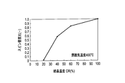
- FIG. 2 is a graph showing the relationship between the crystallinity obtained from the X-ray diffraction characteristics of the CeO 2 (111) plane and the amount of released active oxygen (spin density ratio) for the CeO 2 —Pr composite oxide.
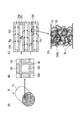
- FIG. 3 is a perspective view and a sectional view showing an example of the filter catalyst according to the embodiment of the present invention.
- FIG. 4 is a system configuration diagram showing an example of an exhaust gas purification system equipped with a filter catalyst according to an embodiment of the present invention.
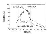
- FIG. 5 is a graph showing the relationship between the crystallinity of the particulate matter purification material and the PM oxidation rate.
- FIG. 6 is a graph showing the relationship between the cerium atomic ratio and the PM oxidation rate in the cerium-praseodymium composite oxide.
- FIG. 7 is a graph showing the relationship between the metal in the particulate matter purification material and the PM oxidation rate.
- the particulate matter purification material (PM purification material) of this embodiment will be described in detail.
- the particulate matter purification material of this embodiment is used for a filter catalyst.
- the filter catalyst is a catalyst that is installed in the exhaust passage of the internal combustion engine, regenerates by capturing PM in the exhaust gas generated by the internal combustion engine, and burning and removing the accumulated PM.
- this particulate matter purification material has a crystallinity of 25 to 60%.
- This crystallinity is represented by the following formula (1).
- Crystallinity (CR) I / I 0 ⁇ 100 (%) (1)
- I in Formula (1) shows the X-ray diffraction peak intensity regarding the (111) plane of the CeO 2 phase in the particulate matter purification material.
- I 0 represents the X-ray diffraction peak intensity relating to the (111) plane of the CeO 2 phase after firing this particulate matter purification material in air at 1000 ° C. and typically after firing at 1000 ° C. for 5 hours.
- the presence state of the cerium oxide and the metal (Me) oxide in the particulate matter purification material in the present embodiment includes a state in which the cerium oxide particles and the metal oxide particles are simply physically mixed. . Further, fine metal oxide particles may be dispersed on and around the surface of the cerium oxide particles, and further, as a composite oxide in which a part of the cerium site in the crystal lattice of the cerium oxide is substituted with the metal atom. A state is good.
- cerium oxide not (CeO 2) itself only refers to the portion having a crystal structure of CeO 2, some parts where the metal atom is inserted into the CeO 2 crystal lattice comprising .
- the main component of the particulate matter purification material in this embodiment is considered to be a portion in which a part of the cerium site in the CeO 2 crystal structure is substituted with the metal atom.
- the crystallinity (CR) is a parameter related to the ripening degree of the crystal structure of the CeO 2 -Me-based composite oxide.
- the present inventors have found that this crystallinity is an important characteristic parameter that characterizes the PM combustion performance of the CeO 2 -Me composite oxide.
- this PM purification material uses CeO 2 as a basic material. Then, it is considered that active oxygen species such as O 2 ⁇ is released from such PM purification material, and PM existing in the vicinity thereof is combusted. Then, it is considered that the amount of released active oxygen species is increased by adding the second component and further the third component to CeO 2 .
- CeO 2 -Me-based material powder and PM powder are mixed well and PM is burned under lean conditions with an oxygen concentration of 10%, compared with the case where CeO 2 is used alone. Further, it is described that the ignition temperature is lowered by several tens of degrees Celsius.
- Non-Patent Document 1 Harada, Y .; Tsushima, A .; Takami, Journal of the Japan Petroleum Institute, 48, (4), 216 (2005)
- the results of measuring the amount of active oxygen produced from each CeO 2 -Me composite oxide in a nitrogen atmosphere at 500 ° C. using an electron spin resonance method (ESR method) are shown in FIG.
- the active species of the spin density ratio is increased - O 2 even in the basic material serving against CeO 2, any material. That is, when the spin density in the case of CeO 2 alone is 1, the spin density of ceria to which any of praseodymium (Pr), yttrium (Y), lanthanum (La), and zirconium (Zr) is added is increased. . In particular, when yttrium (Y) and zirconium (Zr) are added, the spin density is significantly increased.
- this PM purification material is considered to burn PM in the vicinity thereof by releasing active oxygen.
- the present inventors faced the phenomenon that when the various PM purification materials described above are applied to an actual size filter catalyst, PM combustion does not decrease in temperature like the powder in Non-Patent Document 1 described above. And based on this phenomenon, the present inventors are not enough to increase the amount of active oxygen in the low temperature range to further lower the PM combustion temperature, and it is required to reduce the active oxygen release characteristics. Thought.
- the present inventors have searched for various parameters for lowering the PM combustion temperature. As a result, it is not sufficient to simply add the second and third components with CeO 2 as the main component, and attention is paid to the crystallinity of CeO 2 which is a major component of the PM purification material and has an oxygen storage capacity. And it came to the conclusion that controlling it is effective for lowering the temperature of PM combustion.
- Crystallinity is a measure of crystalline CeO 2 (CR), for example, it can be varied by varying the firing temperature of CeO 2.
- the release characteristics of the active oxygen species O 2 ⁇ in the PM purification material in which the crystallinity was changed by firing at different temperatures in an electric furnace were examined. That is, praseodymium-added ceria (CeO 2 —Pr) whose crystallinity was adjusted by firing at different temperatures in air was examined for the spin density of O 2 ⁇ at a relatively low temperature (400 ° C.) by ESR.
- Figure 2 is a crystallinity of praseodymium doped ceria, ambient temperature O 2 in the case of 400 ° C.
- FIG. 2 is a graph showing the relationship between the active species of the spin density.
- FIG. 2 shows the spin density ratio when the crystallinity of praseodymium-added ceria baked at 1000 ° C. in air is 100, and the crystallinity is 100. As shown in FIG. 2, it was found that the amount of active oxygen released (spin density ratio) increases as the degree of crystallinity increases.
- spin density ratio the amount of active oxygen released
- Pt / CeO 2 -Me was prepared by supporting about 0.45% by mass of platinum (Pt) on the praseodymium-added ceria powder having the crystallinity adjusted. Then, about 50 g / L of these supported powders were supported on a typical cordierite alternate plugged filter carrier (diesel particulate filter) having a porosity of 56% to obtain a filter catalyst. Furthermore, these were attached to the exhaust gas piping system of the diesel engine, and after collecting a certain amount of PM, the exhaust gas temperature was gradually increased to evaluate the PM combustion start temperature and the PM combustion speed. As a result, it was confirmed that the higher the crystallization degree, the lowering effect of the PM combustion start temperature was recognized, and the crystallization degree of the material was an important factor.
- the crystallinity of the material is preferably in the range of 25 to 60%. More preferably, it is 40 to 55%, and when it exceeds 60%, the PM combustion characteristics deteriorate rapidly.
- D ⁇ / ⁇ cos ⁇ (nm) (2)
- ⁇ in the formula (2) indicates the wavelength (nm) of the measurement X-ray.
- ⁇ indicates the spread of the diffraction line depending on the size of the crystallite, that is, the half width ⁇ 1/2 (radian) of the diffraction line.
- ⁇ represents the Bragg angle of the diffraction line.
- the crystallite diameter (D) determined using the above formula (2) from the X-ray diffraction peak at the specific crystal plane (111) of CeO 2 of the PM purification material is preferably 10 nm to 22 nm. A more preferable range is 15 to 20 nm in relation to the crystallinity (CR).
- the specific surface area of the PM purification material is preferably 15 to 55 m 2 / g.
- a more preferable range of the specific surface area is 20 to 35 m 2 / g.
- the specific surface area is inversely proportional to the crystallinity.
- the crystallinity exceeds 60% when the specific surface area is 15 m 2 / g or less. In such a case, it is considered preferable from the viewpoint of active oxygen release, but PM combustion characteristics are deteriorated with an actual filter catalyst. The cause is not clear, but it seems that if the specific surface area decreases, it may adversely affect the diffusion process for supplying the generated active oxygen to the PM.
- CeO 2 is used as a compound having an oxygen storage / release capability.
- an oxide material that forms a so-called perovskite structure can also be used as an oxide obtained by adding metal (Me).
- metal Mo
- a La—K—MnO-based composite oxide can be given.
- the CeO 2 -Me-based material according to the PM purification material of the present embodiment various production methods can be adopted, but typically it can be prepared by a coprecipitation method. For example, first, cerium and the nitrates, carbonates, and acetates of the above metals are dissolved in water and mixed thoroughly. Thereafter, an alkali is added to this mixture to form a coprecipitate, which is then washed and then filtered, dried, and calcined.
- CeO 2 —Zr composite oxide first, a mixed aqueous solution of cerium nitrate and zirconium nitrate is prepared. Next, a basic aqueous solution such as diluted ammonia water or urea water is added to the mixed aqueous solution to obtain a coprecipitate. Thereafter, the coprecipitate is filtered, washed with water, dried and fired, whereby a CeO 2 —Zr composite oxide can be obtained.
- a basic aqueous solution such as diluted ammonia water or urea water
- the crystallinity of the CeO 2 -Me material can be controlled, for example, by changing the firing temperature in air. However, it is necessary to adjust the appropriate firing temperature depending on the material used and the manufacturing method of the oxide.
- the PM purification filter catalyst of the present embodiment is obtained by supporting the PM purification material as described above on a filter carrier.
- a filter carrier When such a PM purification material is carried on an actual monolithic filter carrier and used as a filter catalyst, in order to fully exhibit the characteristics of the material and enhance the PM combustion characteristics, the PM purification to the filter carrier is performed. The amount of material loaded is important.
- the filter carrier effective in this embodiment is made of porous ceramics having continuous pores, and various filter carriers (diesel particulate filters) such as those made of silicon carbide, mullite and cordierite are used. Can do.
- the amount of the PM purification material supported on the filter carrier is small, the absolute amount of the released active oxygen is reduced, so that the PM combustion characteristics are deteriorated.
- the amount is too large, the amount of active oxygen is secured, but the pores of the filter carrier are narrowed, resulting in an increase in pressure loss.
- PM does not enter the pores, accumulates and aggregates on the filter wall surface, and PM cannot be burned under a low temperature condition of 600 ° C. or lower. When the temperature is raised to forcibly burn it, the accumulated PM causes self-chain combustion, which may cause thermal runaway.
- the filter carrier with the above-mentioned PM purification material including noble metal at 25 to 100 g per 1 L of the filter carrier to form a catalyst layer.
- the PM purification material including noble metal at 25 to 100 g per 1 L of the filter carrier to form a catalyst layer.
- the PM purification filter catalyst of the present embodiment it is preferable to contain a noble metal in the catalyst layer containing the PM purification material.
- a noble metal platinum (Pt), palladium (Pd), silver (Ag) and a mixture thereof are preferable.
- the PM combustion characteristics can be enhanced by incorporating these precious metals in the catalyst layer in a relatively small loading amount, that is, in the range of 0.25 to 1.0 g per 1 L of the filter carrier.
- the addition of a noble metal is effective in improving the combustion rate of PM.
- Pt is representative as a noble metal, but the amount of Pt supported is preferably 0.3 to 0.7 g / L.
- the noble metal activates hydrocarbons (HC), carbon monoxide (CO), and nitrogen oxides (NOx) present in the exhaust gas, and helps release active oxygen from the PM purification material.
- the amount of the precious metal for that purpose is large, the action may be adversely affected. Therefore, from this point, the above 0.3 to 0.7 g / L is an effective range.
- a platinum as a precious metal is supported at a relatively low concentration of 1.0% by mass or less on a CeO 2 -Me-based material powder.
- Pt / CeO 2 -Me powder was prepared by supporting platinum at a ratio of about 0.5% by mass, and this was prepared with a cell number of 300 cells / in 2 , a wall thickness of 12 mil, and a porosity of 56- Coat 62% cordierite alternating sealed filter carrier.
- the loading amount of the PM purification material is 25 to 100 g / L including precious metals, preferably 40 to 70 g / L. That is, the catalyst layer contains 25 to 100 g / L of the mixture of the particulate matter purification material and the noble metal and 0.25 to 1.0 g / L of the noble metal.
- the average particle size of the particulate matter purification material is preferably 0.1 ⁇ m to 5 ⁇ m. In this case, since the clogging of the pore diameter of the filter carrier can be suppressed while securing a relatively large loading amount, the pressure loss can be suppressed while improving the PM combustion characteristics.
- the average particle diameter of the particulate matter purification material refers to a 50% cumulative particle diameter value (D50) measured by a laser diffraction particle size distribution measuring device.
- a catalyst powder (particulate matter purification material and noble metal) is added with a binder made of water, acid, silica, alumina, or the like to make a slurry. Then, after this catalyst slurry is injected into the filter carrier, pressure is applied to push the slurry into the pores of the filter carrier, and excess slurry is removed with an air flow. Then, a filter catalyst is prepared through a drying and firing process. In this embodiment, it is preferable to coat the catalyst slurry as uniformly as possible in the pores.
- the porosity of the filter carrier used in the present embodiment, a range of 42 to 62% is effective, but the preferable effective range of the porosity varies depending on the material of the filter carrier.
- the porosity is preferably 56 to 62%.
- the filter carrier is made of silicon carbide (SiC)
- the porosity range is preferably 42 to 56%.
- carrier which has such a porosity is marketed, and can be obtained easily.
- FIG. 3 shows an example of the filter catalyst according to the present embodiment.
- 3A is a perspective view of the filter catalyst
- FIG. 3B is an enlarged view showing an end face of the filter catalyst shown in FIG. 3A
- FIG. 3C is FIG. 3A.
- FIG. 3D is a partial enlarged cross-sectional view of the cell wall 12W shown in FIG. 3C.
- the filter catalyst 10 includes a filter carrier 12 and a catalyst layer 20 supported on the carrier 12.
- the filter carrier 12 has a so-called checkered honeycomb type in which a plurality of cells 12C are defined by cell walls 12W and one ends of the cells 12C are alternately plugged (blocked) (FIG. 3B). And (C)).
- the exhaust gas flows into the filter carrier 12 from the open cell 12C at the cell inlet of the filter carrier 12 as indicated by an arrow Eg in FIG. 3C, and passes through the plurality of pores 12Wp of the cell wall 12W. It passes through and flows into the adjacent cell 12C and is discharged through the cell outlet at the open end.
- the pores 12Wp are pores that communicate between adjacent cells 12C so that exhaust gas can pass while supplementing PM.
- Reference numeral 30 denotes PM (see FIG. 3D).
- the catalyst layer 20 is formed by relatively uniformly supporting the catalyst component on the inner surface of the cell wall pores 12Wp, but the catalyst layer is also formed on the outer surface of the cell wall 12W. 20 is formed (not shown).
- the catalyst layer is not only the surface layer filtration method in which the catalyst layer is mainly formed on the outer surface of the cell wall 12W but also the depth filtration method formed in the cell wall pores 12Wp of the filter carrier.
- a combination is adopted.
- the filter catalyst of this embodiment it is the structure which uses effectively the inside of the pore of a cell wall rather than the outer surface of a cell wall.
- Such a combination form makes the characteristics of the above-described PM purification material significantly exhibited because PM30 is easily trapped inside the pores of the cell wall.
- the PM purification material of the present embodiment can also be used in a surface filtration method.
- the filter catalyst as described above is incorporated in an exhaust system of a diesel engine, and as an example, an oxidation catalyst, a filter catalyst, and a NOx trap catalyst are installed in this order from the exhaust upstream side. In this case, the arrangement order of the filter catalyst and the NOx trap catalyst can be reversed.
- the oxidation catalyst and the filter catalyst can be accommodated in a single casing.
- an oxidation catalyst component can be supported on a part of the filter catalyst. The oxidation catalyst oxidizes hydrocarbons and carbon monoxide in the exhaust gas.
- the NOx trap catalyst traps nitrogen oxides in the exhaust gas when the air-fuel ratio of the inflowing exhaust gas is lean, and traps nitrogen oxides when the air-fuel ratio of the inflowing exhaust gas is the stoichiometric air-fuel ratio or rich. Release and reduce.
- FIG. 4 is a system configuration diagram showing an example of an exhaust gas purification system including the filter catalyst of the present embodiment.
- An oxidation catalyst 3, a filter catalyst 10, and a NOx trap catalyst 5 are mounted in order from the upstream side of the exhaust passage 1e of the engine 1.
- the regeneration temperature of the filter catalyst 10 can be lowered to 550 ° C. or lower.
- the filter catalyst 10 is installed in the upstream of the NOx trap catalyst 5, it is hard to be exposed to high temperature and the influence of thermal deterioration can be suppressed.
- the present invention is characterized by maximizing the PM combustion function by controlling the characteristics of the PM purification material. Therefore, its usage is also important.
- the PM accumulated in the filter catalyst is controlled by controlling the internal temperature of the filter catalyst to 800 ° C. or lower. Is preferably burned and removed. This is because it is necessary to maintain the crystallinity and specific surface area of the PM purification material of the present embodiment within an effective range in the actual use process. That is, when the internal temperature of the filter catalyst exceeds 800 ° C., CeO 2 crystal growth in the PM purification material occurs rapidly, and the specific surface area may be significantly reduced.
- the amount of PM collected by the filter catalyst is detected.
- the temperature of the exhaust gas at the inlet of the filter catalyst is set to 350 to 550 ° C.
- the oxygen concentration in the exhaust gas flowing into the filter catalyst is set to 8%. Control over%. If the exhaust gas temperature at the filter catalyst inlet is less than 350 ° C., it is difficult to increase the PM combustion rate.
- PM purification material of this embodiment is used, PM combustion efficiency does not necessarily improve even if the PM combustion speed accompanying the rise in exhaust gas temperature is too high. Further, when the exhaust gas temperature is increased to exceed 600 ° C., the self-chain combustion of PM may occur, and the above-described various problems such as a rapid temperature rise occur.
- the regeneration method of the present embodiment can achieve a high PM combustion speed even under relatively mild conditions at low temperatures, and can realize a high PM combustion removal rate. Furthermore, since the filter catalyst is not exposed to high temperatures, deterioration of the catalyst is also suppressed, and fuel consumption due to high temperatures and adverse effects on engine oil can be eliminated.
- an oxygen control means (not shown) can be provided at the inlet of the filter catalyst 10.
- the oxygen control means is not particularly limited as long as it has a function of controlling the oxygen concentration in the exhaust gas, as in the prior art.
- the oxygen control means can be exemplified by a combination of an exhaust gas recirculation device (EGR device) and an intake air variable device.
- EGR device exhaust gas recirculation device
- means for operating the EGR device and the intake air variable device based on the predictive control disclosed in Japanese Patent No. 3918402 is effective.
- means for introducing secondary air to the catalyst inlet while measuring the oxygen concentration in the exhaust gas can be applied, and some of these means can be used in combination.
- the temperature of the exhaust gas at the inlet of the filter catalyst 10 is 350 ° C. to 550 ° C., and the oxygen concentration of the exhaust gas is 8% or more.
- a means for detecting the pressure loss before and after the filter catalyst 10, for example is provided as a means for predicting and measuring the amount of collected PM, and the amount of collected PM is measured. That is, it is measured whether PM has accumulated and the pressure loss has reached a predetermined value.
- the filter catalyst 10 is regenerated by increasing the temperature of the exhaust gas and holding it until the specified pressure loss is reached.
- the exhaust gas temperature at this time can be controlled by optimizing the post injection amount and timing of the engine 1.
- the pressure loss around the filter catalyst 10 may not increase as expected, and PM may accumulate excessively.
- processing (operation) for gradually increasing the exhaust gas temperature can be performed.
- the filter catalyst 10 exceeds 800 ° C. by monitoring the internal temperature of the filter catalyst 10 and supplying EGR gas. To prevent the temperature from rising.
- the means for predicting the amount of collected PM is not particularly limited.
- a control provided with a central processing unit (CPU) storing a characteristic map in which parameters such as engine speed, accelerator opening, load, exhaust gas temperature and gas amount are associated is stored.
- CPU central processing unit
- a system apparatus etc. can be mentioned.
- CeO 2 -Nd Manufacture of particulate matter purification material (CeO 2 -Nd)
- cerium nitrate and neodymium nitrate were dissolved in ion-exchanged water so that the atomic ratio of cerium and neodymium was 7: 3 to prepare a mixed aqueous solution.
- dilute aqueous ammonia was added to the mixed aqueous solution and stirred to obtain a coprecipitate. Thereafter, the coprecipitate was filtered, washed with water, dried and calcined to prepare a CeO 2 —Nd composite oxide.
- a cordierite honeycomb filter carrier (diameter 5.66 inches, 2.5 L, 300 cpsi) with alternately sealed pores having a porosity of 56% was prepared.
- Each of the catalyst slurries 1 to 14 and 2 ' was sprayed and coated thereon, and then the excess slurry was removed by a compressed air stream, dried at 130 ° C, and calcined at 400 ° C for 3 hours.
- filter catalysts 1 to 14 and 2 'having about 50 g / L of each catalyst layer formed on the filter carrier were obtained.
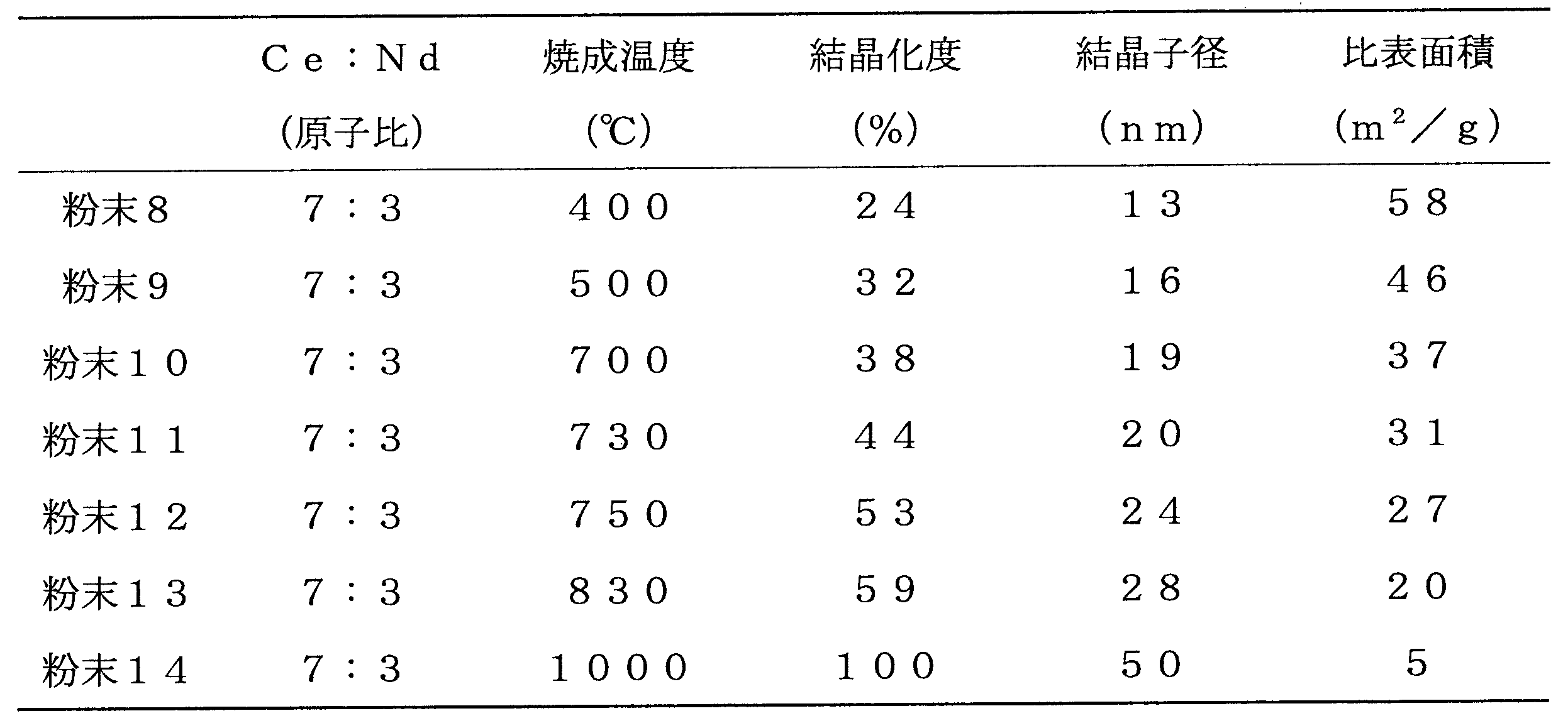
- the CeO 2 —Pr composite oxides 1 to 4 are fired in air in an electric furnace at 700 ° C. for 5 hours, and have different crystallinity, crystallite diameter, and specific surface area as shown in Table 3 below.
- the following four types of powders 15 to 18 were obtained.
- CeO 2 —Y composite oxide CeO 2 —La composite oxide
- CeO 2 —Sr composite oxide CeO 2 —Nb composite
- An oxide and a CeO 2 —Nd composite oxide were prepared.
- the CeO 2 —Zr composite oxide, CeO 2 —Y composite oxide, CeO 2 —La composite oxide, CeO 2 —Sr composite oxide, CeO 2 —Nb composite oxide and CeO 2 —Nd composite oxide are used.
- the product was calcined in an electric furnace at 700 ° C. for 5 hours in air to obtain four types of powders 19 to 24 having different crystallinity, crystallite diameter and specific surface area as shown in Table 4 below.
- 500 g of the powder 21 was immersed in an aqueous silver nitrate (Ag) solution, stirred, further dried to remove moisture, and then fired at 400 ° C. in an electric furnace. Thereby, 1.0 mass% of Ag was supported on the powder 21. Further, 500 g of the obtained 1.0 mass% Ag-supported powder 21 and 2500 g of water were mixed. Next, the mixture was put into an alumina magnetic ball mill, and wet pulverized until the average particle size became 2.1 ⁇ m, whereby a catalyst slurry 21 corresponding to the powder 21 was obtained.
- Ag aqueous silver nitrate
- a catalyst slurry 19 to 24 is coated on a cordierite honeycomb filter carrier to thereby form filter catalysts 15 to 18 each having a catalyst layer of about 50 g / L formed on the filter carrier. Obtained.
- the coating amount was adjusted so that the amount of noble metal supported on the filter carrier was the same as that of the other catalyst slurries.
- the exhaust pipe was switched, and the engine exhaust gas was passed through the filter catalyst via an exhaust gas temperature control device with a built-in heater to regenerate the filter catalyst.
- the engine is operated at a rotational speed of about 1800 rpm
- the inlet temperature of the filter catalyst is set to a predetermined temperature (440 ° C.) using an exhaust gas temperature adjusting device
- the pressure is measured by pressure sensors attached before and after the filter catalyst. Loss was measured.
- the time until the pressure loss returned to the initial value was measured, and further, the weight of the filter catalyst was confirmed to calculate the burning rate (PM oxidation rate) of the deposited PM at the predetermined temperature.
- a cordierite filter carrying nothing on the upstream side of the filter catalyst was installed in order to remove excess PM flowing in.
- the main components and concentration of the exhaust gas during regeneration of the filter catalyst were NOx of 180 ppm or less, NMHC of 100 ppm or less, CO of 800 ppm or less, and O 2 of 10 vol%.
- the fuel used was commercially available JIS No. 2 diesel oil, and the gas space velocity (GHSV) was about 45,000 h ⁇ 1 with respect to the filter catalyst.
- NMHC is an abbreviation for Non-Methane Hydrocarbon and means hydrocarbons excluding methane.
- Figure 5 shows the relationship between the CeO 2 -Pr according to the composite oxide powder of 1 to 7, 2 'and CeO 2 -Nd crystallinity and the PM oxidation rate of the filter catalyst powder 8-14 according to the composite oxide It is a graph.
- the temperature of the exhaust gas at the inlet of the filter catalyst was set to 440 ° C.
- the filter catalyst using the particulate matter purification material (powder 2 to 5 and 9 to 13) according to this embodiment can exhibit a high PM combustion rate at 440 ° C.
- FIG. 7 is a graph showing the relationship between the type of metal (Me) added to CeO 2 and the PM oxidation rate. That is, the PM oxidation rate of the filter catalyst using the powders 3 and 19 to 24 is shown.
- zirconium (Zr), yttrium (Y), lanthanum (La), praseodymium (Pr), strontium (Sr), niobium (Nb), and neodymium (Nd) were used as the metal (Me). It can be seen that all cases show good performance.
- the powder 19 using zirconium as the metal and the powder 21 using lanthanum respectively supported Pd and Ag as the noble metals it can be seen that the filter catalyst according to these powders also shows a high PM oxidation rate. .
- the solid catalyst material that sufficiently exhibits the PM combustion action and the loading conditions on the filter carrier are shown. Furthermore, by showing the optimum use conditions of the filter catalyst, it is possible to realize a filter catalyst that operates from a low temperature and stably exhibits its performance over a long period of time. As a result, it is possible to prevent consumption of excess fuel and to prevent thermal runaway of the filter catalyst due to excessive combustion of PM.
- the particulate matter since a cerium-based material having predetermined characteristics is used, the particulate matter has an excellent particulate matter purification function, can remove the particulate matter from a low temperature, and can suppress thermal runaway of the filter catalyst.
- a purification catalyst, a filter catalyst using the particulate matter purification material, and a method for regenerating the filter catalyst can be provided.
Landscapes
- Chemical & Material Sciences (AREA)
- Engineering & Computer Science (AREA)
- Organic Chemistry (AREA)
- Chemical Kinetics & Catalysis (AREA)
- Materials Engineering (AREA)
- Combustion & Propulsion (AREA)
- Inorganic Chemistry (AREA)
- Geology (AREA)
- Life Sciences & Earth Sciences (AREA)
- Health & Medical Sciences (AREA)
- Mechanical Engineering (AREA)
- Biomedical Technology (AREA)
- Environmental & Geological Engineering (AREA)
- Analytical Chemistry (AREA)
- General Chemical & Material Sciences (AREA)
- Oil, Petroleum & Natural Gas (AREA)
- General Engineering & Computer Science (AREA)
- Geometry (AREA)
- Physics & Mathematics (AREA)
- Catalysts (AREA)
- Exhaust Gas Treatment By Means Of Catalyst (AREA)
- Processes For Solid Components From Exhaust (AREA)
- Exhaust Gas After Treatment (AREA)
Abstract
Description
結晶化度(CR)=I/I0×100(%)…(1)
(式中のIは前記粒子状物質浄化材料におけるCeO2相の(111)面に関するX線回折ピーク強度、I0は前記粒子状物質浄化材料を空気中1000℃で焼成した後におけるCeO2相の(111)面に関するX線回折ピーク強度を示す。)で表される結晶化度(CR)が25~60%である。
本実施形態の粒子状物質浄化材料(PM浄化材料)につき詳細に説明する。本実施形態の粒子状物質浄化材料は、フィルタ触媒に用いられるものである。ここで、フィルタ触媒は内燃機関の排気流路内に設置され、内燃機関で生成した排気ガス中のPMを捕捉し、さらに堆積したPMを燃焼し、除去することにより再生する触媒である。
結晶化度(CR)=I/I0×100(%)…(1)
ここで、式(1)中のIは、粒子状物質浄化材料におけるCeO2相の(111)面に関するX線回折ピーク強度を示す。I0は、この粒子状物質浄化材料を空気中1000℃で焼成した後、典型的には1000℃で5時間焼成した後におけるCeO2相の(111)面に関するX線回折ピーク強度を示す。なお、上記CeO2相の(111)面のX線回折ピークは、2θ=28.5deg付近のピークである。
D=λ/βcosθ(nm)…(2)
ここで、式(2)中のλは測定X線の波長(nm)を示す。βは結晶子の大きさによる回折線の広がり、つまり当該回折線の半価幅β1/2(ラジアン)を示す。また、θは回折線のブラッグ角を示す。そして、当該PM浄化材料のCeO2の特定結晶面(111)におけるX線回折ピークより、上記式(2)を用いて求めた結晶子径(D)は10nm~22nmであることが好ましい。さらに好ましい範囲は、上記結晶化度(CR)との関係で15nm~20nmとなる。
次に、本実施形態の粒子状物質浄化用フィルタ触媒について説明する。本実施形態のPM浄化用フィルタ触媒は、上述のようなPM浄化材料をフィルタ担体に担持したものである。このようなPM浄化材料を実際のモノリス型フィルタ担体に担持してフィルタ触媒とする場合に、該材料の特性を十分に発揮させてPMの燃焼特性を高めるためには、フィルタ担体へのPM浄化材料の担持量が重要となる。なお、本実施形態で有効なフィルタ担体は、連続した細孔を有する多孔質性セラミックスから成るものであり、炭化珪素、ムライト及びコージェライト製など各種のフィルタ担体(ディーゼルパティキュレートフィルタ)を用いることができる。
次に、本実施形態の粒子状物質浄化用フィルタ触媒の再生方法について説明する。本発明は、PM浄化材料の特性を制御することで、PM燃焼機能を最大限発揮させることに特徴がある。したがって、その使用方法も重要である。
(粒子状物質浄化材料(CeO2-Pr)の製造)
まず、硝酸セリウムと硝酸プラセオジムを、セリウムとプラセオジムの原子比が7:3になるようにイオン交換水に溶解し、混合水溶液を調製した。次に、前記混合水溶液に希釈アンモニア水を添加し、攪拌することにより、共沈物を得た。その後、前記共沈物をろ過し、水洗、乾燥及び焼成することにより、CeO2-Pr複合酸化物を調製した。

まず、硝酸セリウムと硝酸ネオジムを、セリウムとネオジムの原子比が7:3になるようにイオン交換水に溶解し、混合水溶液を調製した。次に、前記混合水溶液に希釈アンモニア水を添加し、攪拌することにより、共沈物を得た。その後、前記共沈物をろ過し、水洗、乾燥及び焼成することにより、CeO2-Nd複合酸化物を調製した。
次に、500gの上記粉末1~14を、それぞれジニトロジアンミン白金(Pt)水溶液550gに浸漬し、攪拌し、さらに乾燥して水分を除いた後、電気炉により400℃で焼成した。これにより、粉末1~14にPtを0.45質量%ずつ担持した。さらに得られた0.45質量%Pt担持粉末1~14を500gと、水2500gとを混合した。次に、当該混合物をアルミナの磁性ボールミルに投入し、平均粒径が2.1μmになるまで湿式粉砕することにより、粉末1~14に対応する触媒スラリ1~14を得た。
(粒子状物質浄化材料(CeO2-Pr)の製造)
まず、硝酸セリウムと硝酸プラセオジムを、セリウムとプラセオジムの原子比が5:5になるようにイオン交換水に溶解し、混合水溶液を調製した。次に、前記混合水溶液に希釈アンモニア水を添加し、攪拌することにより、共沈物を得た。その後、前記共沈物をろ過し、水洗、乾燥及び焼成することにより、CeO2-Pr複合酸化物1を調製した。同様にして、セリウムとネオジムの原子比が6:4,9:1及び9.5:0.5のCeO2-Pr複合酸化物2~4を調製した。

まず、上述と同様にして、粉末15~18にPtを0.45質量%ずつ担持した。さらに上述と同様にして、粉末15~18に対応する触媒スラリ15~18を得た。次に、上述と同様にして、コーデェライト製ハニカム状フィルタ担体に、触媒スラリ15~18をそれぞれコーティングすることにより、フィルタ担体上に各触媒層を約50g/L形成したフィルタ触媒15~18を得た。
(粒子状物質浄化材料の製造)
まず、硝酸セリウムと硝酸ジルコニウムを、セリウムとジルコニウムの原子比が7:3になるようにイオン交換水に溶解し、混合水溶液を調製した。次に、前記混合水溶液に希釈アンモニア水を添加し、攪拌することにより、共沈物を得た。その後、前記共沈物をろ過し、水洗、乾燥及び焼成することにより、CeO2-Zr複合酸化物を調製した。同様にして、硝酸イットリウム、硝酸ランタン、硝酸ストロンチウム、硝酸ニオブ及び硝酸ネオジムを用い、CeO2-Y複合酸化物、CeO2-La複合酸化物、CeO2-Sr複合酸化物、CeO2-Nb複合酸化物及びCeO2-Nd複合酸化物を調製した。

次に、500gの上記粉末19を、硝酸パラジウム(Pd)水溶液に浸漬し、攪拌し、さらに乾燥して水分を除いた後、電気炉により400℃で焼成した。これにより、粉末19にPdを0.6質量%担持した。さらに得られた0.6質量%Pd担持粉末19を500gと、水2500gとを混合した。次に、当該混合物をアルミナの磁性ボールミルに投入し、平均粒径が2.1μmになるまで湿式粉砕することにより、粉末19に対応する触媒スラリ19を得た。
図4に示すように、日産自動車株式会社製6気筒2800cc直噴ディーゼルエンジンの排気流路に上記フィルタ触媒1~24及び2’を装着し、回転数約2000rpmにて定常的に運転し、フィルタ触媒に約6g/LのPMを堆積させた。なお、このときのフィルタ触媒内温度は280℃であり、この温度ではPMの燃焼速度は極めて遅いことが確認済みである。
1e 排気流路
3 酸化触媒
5 NOxトラップ触媒
10 フィルタ触媒
12 フィルタ担体
12C セル
12W セル壁
12Wp 細孔
20 触媒層
30 粒子状物質(PM)
Claims (10)
- 内燃機関の排気流路内に設置され、前記内燃機関で生成した排気ガス中の粒子状物質を捕捉し、堆積した前記粒子状物質を燃焼することにより再生する粒子状物質浄化用フィルタ触媒に用いられる粒子状物質浄化材料において、
酸素吸蔵放出能力を有するセリウム(Ce)と、ジルコニウム(Zr)、イットリウム(Y)、ランタン(La)、プラセオジム(Pr)、ストロンチウム(Sr)、ニオブ(Nb)及びネオジム(Nd)から成る群より選ばれた少なくとも1種の金属(Me)と、を含む酸化物を含有し、
セリウムと前記金属の含有比が、原子比でCe:Me=6:4~9:1であり、
次式(1)
結晶化度(CR)=I/I0×100(%)…(1)
(式中のIは前記粒子状物質浄化材料におけるCeO2相の(111)面に関するX線回折ピーク強度、I0は前記粒子状物質浄化材料を空気中1000℃で焼成した後におけるCeO2相の(111)面に関するX線回折ピーク強度を示す。)で表される結晶化度(CR)が25~60%であることを特徴とする粒子状物質浄化材料。 - 前記粒子状物質浄化材料におけるCeO2相の(111)面に関し、Scherrerの式に準拠する次式(2)
D=λ/βcosθ(nm)…(2)
(式中のλは測定X線波長(nm)、βは結晶子の大きさによる回折線の広がり(前記回折線の半価幅β1/2(ラジアン)をとる)、θは回折線のブラッグ角を示す。)で表される結晶子径が、10nm~22nmであることを特徴とする請求項1に記載の粒子状物質浄化材料。 - 比表面積が15~55m2/gの範囲内にあることを特徴とする請求項1又は2に記載の粒子状物質浄化材料。
- 内燃機関の排気流路内に設置され、前記内燃機関で生成した排気ガス中の粒子状物質を捕捉し、堆積した前記粒子状物質を燃焼することにより再生する粒子状物質浄化用フィルタ触媒であって、
連続した細孔を有する多孔質性セラミックスから成るフィルタ担体と、
前記フィルタ担体の壁部に形成される触媒層と、
を備え、
前記触媒層は、前記フィルタ担体の単位容量当たり、請求項1乃至3のいずれか一項に記載の粒子状物質浄化材料及び貴金属の混合物を25~100g/L含有し、且つ、前記貴金属を0.25~1.0g/L含有することを特徴とする粒子状物質浄化用フィルタ触媒。 - 前記フィルタ担体の気孔率が42~62%の範囲内にあることを特徴とする請求項4に記載の粒子状物質浄化用フィルタ触媒。
- 前記フィルタ担体がコージェライト質であり、その気孔率が56~62%の範囲内にあることを特徴とする請求項4又は5に記載の粒子状物質浄化用フィルタ触媒。
- 前記フィルタ担体が炭化珪素(SiC)から成り、その気孔率が42~56%の範囲内にあることを特徴とする請求項4又は5に記載の粒子状物質浄化用フィルタ触媒。
- 前記貴金属が、白金(Pt)、パラジウム(Pd)及び銀(Ag)から成る群より選ばれた少なくとも1種であることを特徴とする請求項4乃至7のいずれか一項に記載の粒子状物質浄化用フィルタ触媒。
- 請求項4乃至8のいずれか一項に記載の粒子状物質浄化用フィルタ触媒を準備する工程と、
前記フィルタ触媒の内部温度を800℃以下に制御することにより、前記フィルタ触媒内に堆積した粒子状物質を燃焼し、除去する工程と、
を有することを特徴とする粒子状物質浄化用フィルタ触媒の再生方法。 - 前記フィルタ触媒への粒子状物質の堆積量を検出する工程と、
前記粒子状物質が一定以上の堆積量となった場合に、前記フィルタ触媒の入口における排気ガスの温度を350~550℃に制御し、且つ、酸素濃度を8%以上に制御することにより、前記粒子状物質を燃焼し、除去する工程と、
をさらに有することを特徴とする請求項9に記載の粒子状物質浄化用フィルタ触媒の再生方法。
Priority Applications (6)
| Application Number | Priority Date | Filing Date | Title |
|---|---|---|---|
| EP09827615.7A EP2363206B1 (en) | 2008-11-21 | 2009-11-20 | Particulate substance removing material, particulate substance removing filter catalyst using particulate substance removing material, and method for regenerating particulate substance removing filter catalyst |
| US13/130,348 US9222382B2 (en) | 2008-11-21 | 2009-11-20 | Particulate matter purifying material, filter catalyst for purifying particulate matter using particulate matter purifying material, and method of regenerating filter catalyst for purifying particulate matter |
| RU2011125352/04A RU2468862C1 (ru) | 2008-11-21 | 2009-11-20 | Очищающий от дисперсных частиц материал, фильтр-катализатор для очистки от дисперсных частиц с использованием очищающего от дисперсных частиц материала и способ регенерирования фильтра-катализатора для очистки от дисперсных частиц |
| CN200980146755XA CN102223951A (zh) | 2008-11-21 | 2009-11-20 | 粒状物净化材料、使用粒状物净化材料的粒状物净化用过滤器催化剂以及粒状物净化用过滤器催化剂的再生方法 |
| BRPI0921967-6A BRPI0921967B1 (pt) | 2008-11-21 | 2009-11-20 | Particulate matter purifying material, filtration catalyst for purifying particulate matter using particulate matter purification material and method of regeneration of filter catalyst to purify particulate matter. |
| JP2010539258A JP5445465B2 (ja) | 2008-11-21 | 2009-11-20 | 粒子状物質浄化材料、粒子状物質浄化材料を用いた粒子状物質浄化用フィルタ触媒及び粒子状物質浄化用フィルタ触媒の再生方法 |
Applications Claiming Priority (2)
| Application Number | Priority Date | Filing Date | Title |
|---|---|---|---|
| JP2008-297932 | 2008-11-21 | ||
| JP2008297932 | 2008-11-21 |
Publications (1)
| Publication Number | Publication Date |
|---|---|
| WO2010058834A1 true WO2010058834A1 (ja) | 2010-05-27 |
Family
ID=42198273
Family Applications (1)
| Application Number | Title | Priority Date | Filing Date |
|---|---|---|---|
| PCT/JP2009/069689 Ceased WO2010058834A1 (ja) | 2008-11-21 | 2009-11-20 | 粒子状物質浄化材料、粒子状物質浄化材料を用いた粒子状物質浄化用フィルタ触媒及び粒子状物質浄化用フィルタ触媒の再生方法 |
Country Status (7)
| Country | Link |
|---|---|
| US (1) | US9222382B2 (ja) |
| EP (1) | EP2363206B1 (ja) |
| JP (1) | JP5445465B2 (ja) |
| CN (1) | CN102223951A (ja) |
| BR (1) | BRPI0921967B1 (ja) |
| RU (1) | RU2468862C1 (ja) |
| WO (1) | WO2010058834A1 (ja) |
Cited By (13)
| Publication number | Priority date | Publication date | Assignee | Title |
|---|---|---|---|---|
| US8173087B2 (en) | 2008-02-05 | 2012-05-08 | Basf Corporation | Gasoline engine emissions treatment systems having particulate traps |
| CN102900495A (zh) * | 2011-07-26 | 2013-01-30 | 通用汽车环球科技运作有限责任公司 | 分层颗粒过滤器再生系统 |
| JP2013530041A (ja) * | 2010-06-16 | 2013-07-25 | サン−ゴバン サントル ドゥ ルシェルシェ エ デトゥードゥ ユーロペン | 電気化学的触媒系 |
| US8815189B2 (en) | 2010-04-19 | 2014-08-26 | Basf Corporation | Gasoline engine emissions treatment systems having particulate filters |
| JP2015077578A (ja) * | 2013-10-18 | 2015-04-23 | 株式会社キャタラー | ディーゼル微粒子捕集フィルター触媒 |
| JP2015098015A (ja) * | 2013-10-15 | 2015-05-28 | 本田技研工業株式会社 | 排気浄化フィルタ |
| CN105874178A (zh) * | 2013-12-30 | 2016-08-17 | 庄信万丰股份有限公司 | 废气气体处理催化剂 |
| JPWO2014123232A1 (ja) * | 2013-02-08 | 2017-02-02 | ユミコア日本触媒株式会社 | NOx吸蔵還元型排ガス浄化用触媒および当該触媒を用いた排ガス浄化方法 |
| WO2017022407A1 (ja) * | 2015-07-31 | 2017-02-09 | 株式会社デンソー | 排ガス浄化フィルタ |
| JP2018513298A (ja) * | 2015-03-23 | 2018-05-24 | ハルドール・トプサー・アクチエゼルスカベット | エンジン排ガス又はプロセス装置から粒状物質を除去するための方法及びシステム |
| WO2018155944A1 (ko) * | 2017-02-23 | 2018-08-30 | 김재수 | 매연저감 조성물 |
| JP2020131181A (ja) * | 2019-02-26 | 2020-08-31 | トヨタ自動車株式会社 | ハニカム構造体 |
| JP2022073362A (ja) * | 2020-10-30 | 2022-05-17 | 新日本電工株式会社 | 窒素酸化物吸着材料及び自動車排ガス触媒 |
Families Citing this family (9)
| Publication number | Priority date | Publication date | Assignee | Title |
|---|---|---|---|---|
| FR2962431B1 (fr) * | 2010-07-07 | 2018-01-19 | Rhodia Operations | Composition a base d'oxydes de cerium, de niobium et, eventuellement, de zirconium et son utilisation en catlyse. |
| JP2012154259A (ja) * | 2011-01-26 | 2012-08-16 | Mazda Motor Corp | 排気ガス浄化用触媒装置 |
| EP2481473A3 (en) * | 2011-01-26 | 2012-08-15 | Ford Global Technologies, LLC | LNT and SCR catalysts for combined LNT-SCR applications |
| DE102012218475A1 (de) * | 2011-10-10 | 2013-04-18 | Heesung Catalysts Corp. | Katalysator ohne PGM zum Verbrennen von Kohlenstoffruß sowie Filtrationsfilter und Vorrichtung zur Nachbearbeitung von Abgasen, welche diesen verwendet |
| US9108155B2 (en) | 2011-10-10 | 2015-08-18 | Hyundai Motor Company | Non-PGM catalyst for burning carbon soot, and filtration filter and exhaust gas post-processing apparatus using the same |
| US9155999B2 (en) | 2011-10-10 | 2015-10-13 | Hyundai Motor Company | Non-PGM catalyst for burning carbon soot, and filtration filter and exhaust gas post-processing apparatus using the same |
| JP2015093227A (ja) * | 2013-11-11 | 2015-05-18 | スズキ株式会社 | 排ガス浄化触媒とその製造方法 |
| WO2016071449A1 (en) * | 2014-11-06 | 2016-05-12 | Basf Se | Mixed metal oxide composite for oxygen storage |
| DE102021107130B4 (de) | 2021-03-23 | 2022-12-29 | Umicore Ag & Co. Kg | Vorrichtung zur Erhöhung der Frischfiltration von Benzinpartikelfiltern |
Citations (8)
| Publication number | Priority date | Publication date | Assignee | Title |
|---|---|---|---|---|
| JPH0442063B2 (ja) | 1983-10-04 | 1992-07-10 | Nippon Shokubai Kk | |
| JPH08291705A (ja) | 1995-04-21 | 1996-11-05 | Matsushita Electric Ind Co Ltd | フィルタ再生装置 |
| JP2004016931A (ja) * | 2002-06-17 | 2004-01-22 | Nissan Motor Co Ltd | 排気ガス浄化触媒 |
| JP3560408B2 (ja) | 1996-02-15 | 2004-09-02 | 株式会社日本自動車部品総合研究所 | ディーゼル排ガス浄化フィルタおよびその製造方法 |
| JP3613669B2 (ja) | 2000-01-19 | 2005-01-26 | トヨタ自動車株式会社 | 内燃機関の排気浄化装置 |
| JP2006275020A (ja) * | 2005-03-30 | 2006-10-12 | Denso Corp | 排気温度制御装置 |
| JP2006326573A (ja) | 2005-04-27 | 2006-12-07 | Mazda Motor Corp | ディーゼルパティキュレートフィルタ |
| JP3918402B2 (ja) | 2000-05-18 | 2007-05-23 | 日産自動車株式会社 | ディーゼルエンジンの制御装置 |
Family Cites Families (13)
| Publication number | Priority date | Publication date | Assignee | Title |
|---|---|---|---|---|
| JP4053623B2 (ja) * | 1996-12-27 | 2008-02-27 | 阿南化成株式会社 | ジルコニウム−セリウム系複合酸化物及びその製造方法 |
| US6528451B2 (en) * | 2001-03-13 | 2003-03-04 | W.R. Grace & Co.-Conn. | Catalyst support material having high oxygen storage capacity and method of preparation thereof |
| JP3946982B2 (ja) * | 2001-11-01 | 2007-07-18 | ニッケイ・メル株式会社 | ジルコニア・セリア基複合酸化物の製造方法 |
| US7871957B2 (en) * | 2002-03-28 | 2011-01-18 | Utc Power Corporation | Catalyst support of mixed cerium zirconium titanium oxide, including use and method of making |
| FR2875149B1 (fr) * | 2004-09-15 | 2006-12-15 | Rhodia Chimie Sa | Procede de fabrication d'un filtre a particules catalyse et filtre ainsi obtenu |
| JP5200315B2 (ja) * | 2004-12-22 | 2013-06-05 | 日産自動車株式会社 | 排気ガス浄化触媒、及び排気ガス浄化触媒の製造方法 |
| CN1854474A (zh) * | 2005-04-27 | 2006-11-01 | 马自达汽车股份有限公司 | 柴油汽车尾气微粒子过滤器 |
| US7243488B2 (en) * | 2005-08-30 | 2007-07-17 | Delphi Technologies, Inc. | Method and apparatus for controlling regeneration temperature in a diesel particulate trap |
| DK1991354T3 (da) | 2006-02-17 | 2020-03-16 | Rhodia Recherches Et Tech | Sammensætning på basis af zirconium-, cerium-, yttrium- og lanthanoxid og et yderligere sjældent jordartsmetals oxid, fremgangsmåde til fremstilling heraf og katalytisk anvendelse heraf |
| CN101415490A (zh) | 2006-03-28 | 2009-04-22 | 株式会社丰田中央研究所 | 废气净化用催化剂、该催化剂的再生方法、以及使用该催化剂的废气净化用设备和方法 |
| FR2905371B1 (fr) * | 2006-08-31 | 2010-11-05 | Rhodia Recherches & Tech | Composition a reductibilite elevee a base d'un oxyde de cerium nanometrique sur un support, procede de preparation et utilisation comme catalyseur |
| EP1920831B1 (en) * | 2006-11-08 | 2020-06-03 | Nissan Motor Co., Ltd. | Compound oxide-based particulate matter oxidizing catalyst |
| JP4321615B2 (ja) * | 2007-03-28 | 2009-08-26 | トヨタ自動車株式会社 | 内燃機関装置およびその制御方法並びに内燃機関装置を搭載する車両 |
-
2009
- 2009-11-20 JP JP2010539258A patent/JP5445465B2/ja active Active
- 2009-11-20 CN CN200980146755XA patent/CN102223951A/zh active Pending
- 2009-11-20 WO PCT/JP2009/069689 patent/WO2010058834A1/ja not_active Ceased
- 2009-11-20 US US13/130,348 patent/US9222382B2/en active Active
- 2009-11-20 BR BRPI0921967-6A patent/BRPI0921967B1/pt not_active IP Right Cessation
- 2009-11-20 RU RU2011125352/04A patent/RU2468862C1/ru active
- 2009-11-20 EP EP09827615.7A patent/EP2363206B1/en active Active
Patent Citations (8)
| Publication number | Priority date | Publication date | Assignee | Title |
|---|---|---|---|---|
| JPH0442063B2 (ja) | 1983-10-04 | 1992-07-10 | Nippon Shokubai Kk | |
| JPH08291705A (ja) | 1995-04-21 | 1996-11-05 | Matsushita Electric Ind Co Ltd | フィルタ再生装置 |
| JP3560408B2 (ja) | 1996-02-15 | 2004-09-02 | 株式会社日本自動車部品総合研究所 | ディーゼル排ガス浄化フィルタおよびその製造方法 |
| JP3613669B2 (ja) | 2000-01-19 | 2005-01-26 | トヨタ自動車株式会社 | 内燃機関の排気浄化装置 |
| JP3918402B2 (ja) | 2000-05-18 | 2007-05-23 | 日産自動車株式会社 | ディーゼルエンジンの制御装置 |
| JP2004016931A (ja) * | 2002-06-17 | 2004-01-22 | Nissan Motor Co Ltd | 排気ガス浄化触媒 |
| JP2006275020A (ja) * | 2005-03-30 | 2006-10-12 | Denso Corp | 排気温度制御装置 |
| JP2006326573A (ja) | 2005-04-27 | 2006-12-07 | Mazda Motor Corp | ディーゼルパティキュレートフィルタ |
Non-Patent Citations (2)
| Title |
|---|
| K. HARADA, Y. TSUSHIO, A. TAKAMI, JOURNAL OF THE JAPAN PETROLEUM INSTITUTE, vol. 48, no. 4, 2005, pages 216 |
| See also references of EP2363206A4 |
Cited By (15)
| Publication number | Priority date | Publication date | Assignee | Title |
|---|---|---|---|---|
| US8173087B2 (en) | 2008-02-05 | 2012-05-08 | Basf Corporation | Gasoline engine emissions treatment systems having particulate traps |
| US8815189B2 (en) | 2010-04-19 | 2014-08-26 | Basf Corporation | Gasoline engine emissions treatment systems having particulate filters |
| JP2013530041A (ja) * | 2010-06-16 | 2013-07-25 | サン−ゴバン サントル ドゥ ルシェルシェ エ デトゥードゥ ユーロペン | 電気化学的触媒系 |
| CN102900495A (zh) * | 2011-07-26 | 2013-01-30 | 通用汽车环球科技运作有限责任公司 | 分层颗粒过滤器再生系统 |
| JPWO2014123232A1 (ja) * | 2013-02-08 | 2017-02-02 | ユミコア日本触媒株式会社 | NOx吸蔵還元型排ガス浄化用触媒および当該触媒を用いた排ガス浄化方法 |
| JP2015098015A (ja) * | 2013-10-15 | 2015-05-28 | 本田技研工業株式会社 | 排気浄化フィルタ |
| JP2015077578A (ja) * | 2013-10-18 | 2015-04-23 | 株式会社キャタラー | ディーゼル微粒子捕集フィルター触媒 |
| CN105874178A (zh) * | 2013-12-30 | 2016-08-17 | 庄信万丰股份有限公司 | 废气气体处理催化剂 |
| JP2017502838A (ja) * | 2013-12-30 | 2017-01-26 | ジョンソン、マッセイ、パブリック、リミテッド、カンパニーJohnson Matthey Public Limited Company | 排ガス処理触媒 |
| JP2018513298A (ja) * | 2015-03-23 | 2018-05-24 | ハルドール・トプサー・アクチエゼルスカベット | エンジン排ガス又はプロセス装置から粒状物質を除去するための方法及びシステム |
| WO2017022407A1 (ja) * | 2015-07-31 | 2017-02-09 | 株式会社デンソー | 排ガス浄化フィルタ |
| JP2017029916A (ja) * | 2015-07-31 | 2017-02-09 | 株式会社デンソー | 排ガス浄化フィルタ |
| WO2018155944A1 (ko) * | 2017-02-23 | 2018-08-30 | 김재수 | 매연저감 조성물 |
| JP2020131181A (ja) * | 2019-02-26 | 2020-08-31 | トヨタ自動車株式会社 | ハニカム構造体 |
| JP2022073362A (ja) * | 2020-10-30 | 2022-05-17 | 新日本電工株式会社 | 窒素酸化物吸着材料及び自動車排ガス触媒 |
Also Published As
| Publication number | Publication date |
|---|---|
| US20110219748A1 (en) | 2011-09-15 |
| CN102223951A (zh) | 2011-10-19 |
| JP5445465B2 (ja) | 2014-03-19 |
| EP2363206A4 (en) | 2015-04-15 |
| EP2363206A1 (en) | 2011-09-07 |
| JPWO2010058834A1 (ja) | 2012-04-19 |
| BRPI0921967A2 (pt) | 2016-01-05 |
| BRPI0921967B1 (pt) | 2017-11-07 |
| EP2363206B1 (en) | 2018-08-15 |
| RU2468862C1 (ru) | 2012-12-10 |
| US9222382B2 (en) | 2015-12-29 |
Similar Documents
| Publication | Publication Date | Title |
|---|---|---|
| JP5445465B2 (ja) | 粒子状物質浄化材料、粒子状物質浄化材料を用いた粒子状物質浄化用フィルタ触媒及び粒子状物質浄化用フィルタ触媒の再生方法 | |
| EP1967263B1 (en) | Catalytic Material And Catalyst For Purifying Exhaust Gas Component | |
| US7673448B2 (en) | Diesel exhaust article and catalyst compositions therefor | |
| US8544261B2 (en) | Exhaust gas purification catalyst and exhaust gas purification apparatus using the exhaust gas purification catalyst | |
| CN102112211A (zh) | NOx存储材料和耐热老化捕集器 | |
| WO2014002772A1 (ja) | ディーゼルパティキュレートフィルタ及び排気ガス浄化装置 | |
| JP6378169B2 (ja) | ディーゼルエンジン排気ガス浄化用の軽油の酸化触媒及びそれを用いたディーゼルエンジンの排気ガス浄化装置 | |
| JP2006326573A (ja) | ディーゼルパティキュレートフィルタ | |
| KR101855537B1 (ko) | Rh 로딩량이 감소된 NOx 저장 촉매 | |
| JP5023969B2 (ja) | 排ガス成分浄化用触媒材及び同触媒材付パティキュレートフィルタ | |
| JP5954159B2 (ja) | 触媒付パティキュレートフィルタ | |
| JP4978581B2 (ja) | パティキュレートフィルタ | |
| JP4618046B2 (ja) | ディーゼルパティキュレートフィルタ | |
| JP5861475B2 (ja) | 排ガス成分浄化触媒材及びそれを備えた触媒材付きパティキュレートフィルタ | |
| JP5023950B2 (ja) | 排ガス成分浄化用触媒材及び同触媒材付パティキュレートフィルタ | |
| JP2014100662A (ja) | 触媒付パティキュレートフィルタ | |
| JP5029273B2 (ja) | パティキュレートフィルタ | |
| JP5939140B2 (ja) | 触媒付パティキュレートフィルタ | |
| JP5949520B2 (ja) | 触媒付パティキュレートフィルタ | |
| JP5942812B2 (ja) | 触媒付パティキュレートフィルタ | |
| CN105473222B (zh) | 尾气净化用催化剂及其制备方法 | |
| JP5954134B2 (ja) | 触媒付パティキュレートフィルタ | |
| JP2004330115A (ja) | 排気ガス浄化用触媒及びその製造方法 |
Legal Events
| Date | Code | Title | Description |
|---|---|---|---|
| WWE | Wipo information: entry into national phase |
Ref document number: 200980146755.X Country of ref document: CN |
|
| 121 | Ep: the epo has been informed by wipo that ep was designated in this application |
Ref document number: 09827615 Country of ref document: EP Kind code of ref document: A1 |
|
| DPE1 | Request for preliminary examination filed after expiration of 19th month from priority date (pct application filed from 20040101) | ||
| ENP | Entry into the national phase |
Ref document number: 2010539258 Country of ref document: JP Kind code of ref document: A |
|
| WWE | Wipo information: entry into national phase |
Ref document number: 13130348 Country of ref document: US |
|
| NENP | Non-entry into the national phase |
Ref country code: DE |
|
| WWE | Wipo information: entry into national phase |
Ref document number: 2009827615 Country of ref document: EP |
|
| WWE | Wipo information: entry into national phase |
Ref document number: 2477/KOLNP/2011 Country of ref document: IN |
|
| WWE | Wipo information: entry into national phase |
Ref document number: 2011125352 Country of ref document: RU |
|
| ENP | Entry into the national phase |
Ref document number: PI0921967 Country of ref document: BR Kind code of ref document: A2 Effective date: 20110520 |