WO2010061796A1 - インクジェットプリンタ - Google Patents
インクジェットプリンタ Download PDFInfo
- Publication number
- WO2010061796A1 WO2010061796A1 PCT/JP2009/069727 JP2009069727W WO2010061796A1 WO 2010061796 A1 WO2010061796 A1 WO 2010061796A1 JP 2009069727 W JP2009069727 W JP 2009069727W WO 2010061796 A1 WO2010061796 A1 WO 2010061796A1
- Authority
- WO
- WIPO (PCT)
- Prior art keywords
- waveguide
- ink
- medium
- microwave
- magnetron
- Prior art date
- Legal status (The legal status is an assumption and is not a legal conclusion. Google has not performed a legal analysis and makes no representation as to the accuracy of the status listed.)
- Ceased
Links
Images








Classifications
-
- H—ELECTRICITY
- H05—ELECTRIC TECHNIQUES NOT OTHERWISE PROVIDED FOR
- H05B—ELECTRIC HEATING; ELECTRIC LIGHT SOURCES NOT OTHERWISE PROVIDED FOR; CIRCUIT ARRANGEMENTS FOR ELECTRIC LIGHT SOURCES, IN GENERAL
- H05B6/00—Heating by electric, magnetic or electromagnetic fields
- H05B6/64—Heating using microwaves
- H05B6/80—Apparatus for specific applications
-
- B—PERFORMING OPERATIONS; TRANSPORTING
- B41—PRINTING; LINING MACHINES; TYPEWRITERS; STAMPS
- B41J—TYPEWRITERS; SELECTIVE PRINTING MECHANISMS, i.e. MECHANISMS PRINTING OTHERWISE THAN FROM A FORME; CORRECTION OF TYPOGRAPHICAL ERRORS
- B41J11/00—Devices or arrangements of selective printing mechanisms, e.g. ink-jet printers or thermal printers, for supporting or handling copy material in sheet or web form
- B41J11/0015—Devices or arrangements of selective printing mechanisms, e.g. ink-jet printers or thermal printers, for supporting or handling copy material in sheet or web form for treating before, during or after printing or for uniform coating or laminating the copy material before or after printing
- B41J11/002—Curing or drying the ink on the copy materials, e.g. by heating or irradiating
-
- B—PERFORMING OPERATIONS; TRANSPORTING
- B41—PRINTING; LINING MACHINES; TYPEWRITERS; STAMPS
- B41J—TYPEWRITERS; SELECTIVE PRINTING MECHANISMS, i.e. MECHANISMS PRINTING OTHERWISE THAN FROM A FORME; CORRECTION OF TYPOGRAPHICAL ERRORS
- B41J11/00—Devices or arrangements of selective printing mechanisms, e.g. ink-jet printers or thermal printers, for supporting or handling copy material in sheet or web form
- B41J11/0015—Devices or arrangements of selective printing mechanisms, e.g. ink-jet printers or thermal printers, for supporting or handling copy material in sheet or web form for treating before, during or after printing or for uniform coating or laminating the copy material before or after printing
- B41J11/002—Curing or drying the ink on the copy materials, e.g. by heating or irradiating
- B41J11/0021—Curing or drying the ink on the copy materials, e.g. by heating or irradiating using irradiation
- B41J11/00216—Curing or drying the ink on the copy materials, e.g. by heating or irradiating using irradiation using infrared [IR] radiation or microwaves
-
- H—ELECTRICITY
- H05—ELECTRIC TECHNIQUES NOT OTHERWISE PROVIDED FOR
- H05B—ELECTRIC HEATING; ELECTRIC LIGHT SOURCES NOT OTHERWISE PROVIDED FOR; CIRCUIT ARRANGEMENTS FOR ELECTRIC LIGHT SOURCES, IN GENERAL
- H05B6/00—Heating by electric, magnetic or electromagnetic fields
- H05B6/64—Heating using microwaves
- H05B6/642—Cooling of the microwave components and related air circulation systems
-
- H—ELECTRICITY
- H05—ELECTRIC TECHNIQUES NOT OTHERWISE PROVIDED FOR
- H05B—ELECTRIC HEATING; ELECTRIC LIGHT SOURCES NOT OTHERWISE PROVIDED FOR; CIRCUIT ARRANGEMENTS FOR ELECTRIC LIGHT SOURCES, IN GENERAL
- H05B6/00—Heating by electric, magnetic or electromagnetic fields
- H05B6/64—Heating using microwaves
- H05B6/70—Feed lines
- H05B6/701—Feed lines using microwave applicators
-
- H—ELECTRICITY
- H05—ELECTRIC TECHNIQUES NOT OTHERWISE PROVIDED FOR
- H05B—ELECTRIC HEATING; ELECTRIC LIGHT SOURCES NOT OTHERWISE PROVIDED FOR; CIRCUIT ARRANGEMENTS FOR ELECTRIC LIGHT SOURCES, IN GENERAL
- H05B6/00—Heating by electric, magnetic or electromagnetic fields
- H05B6/64—Heating using microwaves
- H05B6/74—Mode transformers or mode stirrers
- H05B6/745—Rotatable stirrers
-
- H—ELECTRICITY
- H05—ELECTRIC TECHNIQUES NOT OTHERWISE PROVIDED FOR
- H05B—ELECTRIC HEATING; ELECTRIC LIGHT SOURCES NOT OTHERWISE PROVIDED FOR; CIRCUIT ARRANGEMENTS FOR ELECTRIC LIGHT SOURCES, IN GENERAL
- H05B6/00—Heating by electric, magnetic or electromagnetic fields
- H05B6/64—Heating using microwaves
- H05B6/78—Arrangements for continuous movement of material
- H05B6/788—Arrangements for continuous movement of material wherein an elongated material is moved by applying a mechanical tension to it
-
- H—ELECTRICITY
- H05—ELECTRIC TECHNIQUES NOT OTHERWISE PROVIDED FOR
- H05B—ELECTRIC HEATING; ELECTRIC LIGHT SOURCES NOT OTHERWISE PROVIDED FOR; CIRCUIT ARRANGEMENTS FOR ELECTRIC LIGHT SOURCES, IN GENERAL
- H05B6/00—Heating by electric, magnetic or electromagnetic fields
- H05B6/64—Heating using microwaves
- H05B6/80—Apparatus for specific applications
- H05B6/802—Apparatus for specific applications for heating fluids
-
- H—ELECTRICITY
- H05—ELECTRIC TECHNIQUES NOT OTHERWISE PROVIDED FOR
- H05B—ELECTRIC HEATING; ELECTRIC LIGHT SOURCES NOT OTHERWISE PROVIDED FOR; CIRCUIT ARRANGEMENTS FOR ELECTRIC LIGHT SOURCES, IN GENERAL
- H05B2206/00—Aspects relating to heating by electric, magnetic, or electromagnetic fields covered by group H05B6/00
- H05B2206/04—Heating using microwaves
- H05B2206/046—Microwave drying of wood, ink, food, ceramic, sintering of ceramic, clothes, hair
Definitions
- the present invention relates to an ink jet printer that forms an image or the like on a medium by ejecting ink.
- dye-based inks such as acid dyes, reactive dyes, direct dyes, solvent inks, etc. on the surface or front and back surfaces of sheet-like media (recording media) such as paper, silk, cotton, and vinyl chloride Printing is performed by discharging the organic solvent pigment ink.
- sheet-like media such as paper, silk, cotton, and vinyl chloride
- Printing is performed by discharging the organic solvent pigment ink.
- Patent Document 1 considers an ink jet printer that dries ink ejected to a medium by inserting the medium through a waveguide to which microwaves are supplied.
- an object of the present invention is to provide an ink jet printer that can improve the drying speed of ink ejected to a medium in an ink jet printer using a waveguide.
- An ink jet printer includes an ejection unit that ejects ink toward a medium, a waveguide through which the medium on which the ink is ejected by the ejection unit is inserted, and a start end of the waveguide.
- An electromagnetic wave supplying means for supplying electromagnetic waves to the waveguide, a rotary reflecting member provided at the end of the waveguide for rotating and reflecting the electromagnetic waves supplied by the electromagnetic wave supplying means, and ventilating the inside of the waveguide And ventilation means.
- the medium on which the ink is ejected by the ejection means is inserted into the waveguide to which the electromagnetic wave is supplied by the electromagnetic wave supply means. For this reason, the ink discharged to the medium is dried by this electromagnetic wave. Since the electromagnetic wave supplied by the electromagnetic wave supply means propagates through the waveguide and is reflected by the rotary reflecting member at the terminal portion, the ink discharged onto the medium is dried again by the reflected electromagnetic wave. Is done. Then, since the inside of the waveguide is ventilated by the ventilation means, the solvent vapor of the ink vaporized by the electromagnetic wave is forcibly discharged out of the waveguide, thereby improving the drying speed of the ink ejected to the medium.
- the rotating reflection member rotates, the reflection direction of the electromagnetic wave reflected by the rotating reflection member changes, so that the constant wave generated by the electromagnetic wave supplied by the electromagnetic wave supply means and the electromagnetic wave reflected by the rotary reflection member.
- the standing wave fluctuates. Thereby, since the peak position of the standing wave fluctuates in the waveguide, it is possible to suppress uneven drying of the ink ejected to the medium.
- the ventilating means is preferably provided at the start and end portions of the waveguide.
- the ventilation means is provided at the start and end portions of the waveguide, the gas flow in the waveguide can be made uniform, and uneven drying of the ink can be suppressed.
- the ventilation means preferably sends warm air into the waveguide. According to this inkjet printer, the drying speed of ink can be further improved by sending warm air into the waveguide.
- the temperature of the hot air is preferably 40 ° C. to 60 ° C.
- the temperature of the hot air is preferably 40 ° C. to 60 ° C.
- the electromagnetic wave supply means supplies an electromagnetic wave generated by power of 400 W or more to the waveguide.
- the drying speed of ink can be improved by supplying electromagnetic waves generated by power of 400 W or more to the waveguide.
- the drying speed of the ink ejected to the medium can be improved.
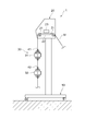
- FIG. 1 is a perspective view of an ink jet printer according to an embodiment. It is sectional drawing of the inkjet printer shown in FIG. It is a perspective view of a waveguide. It is a top view of a waveguide. It is a perspective perspective view of a rotation reflection part. It is a longitudinal cross-sectional view of a rotation reflection part. It is a disassembled perspective view of a ventilation member. It is the figure which showed the rotation angle of the propeller part in a rotation reflection part. It is the figure which showed the state of the standing wave in each rotation angle of the propeller part shown in FIG. It is the photograph which imaged the medium dried in Example 2. FIG. It is the figure which represented the experimental result of Table 4 on the graph.
- Example 3 is a diagram showing a comparison between 3 and Comparative Example 3.
- FIG. It is the photograph which imaged the media which dried and cut in Example 4.
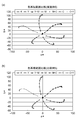
- FIG. It is a figure which shows the experimental result of Example 5, (a) is the figure which showed the color reproduction range of each color in Example 5, (b) showed the color reproduction range of each color in Comparative Example 5.
- FIG. It is the figure which showed the comparison of the experimental result of Example 5 and Comparative Example 5.
- FIG. 1 is a perspective view of the ink jet printer according to the present embodiment
- FIG. 2 is a cross-sectional view of the ink jet printer shown in FIG.
- the inkjet printer 1 As shown in FIGS. 1 and 2, the inkjet printer 1 according to this embodiment is mounted on a base 10 and ejects ink onto a medium M.
- the printer unit 20 ejects ink onto the medium M at the printer unit 20.
- a waveguide 30 for drying ink As the medium M, a sheet-like print medium is used, and is made of, for example, paper, silk, cotton, vinyl chloride, or the like.
- dye-based inks such as acid dyes, reactive dyes, and direct dyes, and organic solvent-based inks such as solvent are used.
- the printer unit 20 includes a transport roller 21 that transports the medium M, an inkjet head 23 that ejects ink onto the medium M on the platen 22, and a toner unit that stores an ink tank that stores ink ejected from the inkjet head 23. 24 and an operation unit 25 on which a user performs operation input are provided.
- FIG. 3 is a perspective view of the waveguide
- FIG. 4 is a plan view of the waveguide.
- the waveguide 30 is an elongated waveguide having a rectangular cross section, and has a two-stage shape bent in a substantially U shape at the center.
- the waveguide 30 includes waveguide bodies 31 and 32, a bent portion 33, an electromagnetic wave supply unit 34, a propagation blocking unit 35, a matching unit 36, a rotary reflection unit 37, and ventilation units 38 and 39. It consists of and.
- the waveguide main bodies 31 and 32, the bending part 33, the electromagnetic wave supply part 34, the propagation prevention part 35, the rotation reflection part 37, and the ventilation parts 38 and 39 are each formed with a flange part on the end face. These flange portions are overlapped and connected to each other so that the electromagnetic wave supply unit 34 and the propagation blocking unit 35, the propagation blocking unit 35 and the matching unit 36, the matching unit 36 and the ventilation unit 38, and the ventilation unit 38 and the waveguide are guided.
- the tube body 31, the waveguide body 31 and the bent portion 33, the bent portion 33 and the waveguide body 32, the waveguide body 32 and the ventilation portion 39, and the ventilation portion 39 and the rotation reflection portion 37 are connected to each other. .
- the waveguide main bodies 31 and 32 are formed to be long, and dry ink ejected to the medium M by microwaves. For this reason, the waveguide bodies 31 and 32 are formed with insertion ports 41 and 42 through which the media M, on which ink is ejected by the inkjet head 23, is inserted into the waveguide bodies 31 and 32, respectively.
- the bent portion 33 is formed in a substantially U shape, and is disposed between the waveguide main body 31 and the waveguide main body 32 so that the waveguide main body 31 and the waveguide main body 32 are arranged in two upper and lower stages. To be linked.
- the electromagnetic wave supply unit 34 is disposed at the start end of the waveguide 30 and is attached with a magnetron 43 that generates microwaves.
- the magnetron 43 generates microwaves, supplies the microwaves into the waveguide 30, and transports the microwaves in the forward directions D1 and D2 in the waveguide 30. Note that the frequency of the microwave supplied from the magnetron 43 to the waveguide 30 is ⁇ g.
- the propagation blocking unit 35 is disposed between the waveguide main body 31 and the electromagnetic wave supply unit 34, and is attached with an isolator 44 that propagates microwaves only in one direction.
- the isolator 44 is configured by a known isolator and propagates microwaves from the electromagnetic wave supply unit 34 toward the waveguide body 31, but propagates microwaves from the waveguide body 31 toward the electromagnetic wave supply unit 34. It is a deterrent.
- the matching unit 36 is disposed between the propagation blocking unit 35 and the ventilation unit 38, and the microwave matching unit 45 is attached to the matching unit 36.
- the microwave matching unit 45 is configured by a known microwave matching unit. The impedance matching is performed in the matching unit 36 to reduce the reflected power of the microwave supplied from the magnetron 43, and the microwave matching unit 45 is discharged to the medium M. This improves the efficiency of absorbing microwaves with respect to ink.
- the rotary reflection portion 37 is disposed at the end portion of the waveguide 30 and performs reflection termination processing of the microwave supplied into the waveguide 30.
- FIG. 5 is a perspective perspective view of the rotary reflection portion
- FIG. 6 is a longitudinal sectional view of the rotary reflection portion.
- the rotary reflecting portion 37 is provided with a propeller member 60 and a short-circuit plate 90.
- the propeller member 60 reflects and terminates the microwave supplied from the magnetron 43 and fluctuates and disturbs the standing wave generated in the waveguide 30. For this reason, the propeller member 60 includes a propeller portion 61 and a motor portion 62 that rotates the propeller portion 61.
- the propeller portion 61 is disposed in the rotation reflection portion 37 and is formed on a flat plate having the same shape as the inner cross section of the rotation reflection portion 37, separated from the inner wall of the rotation reflection portion 37 by a predetermined distance. And the propeller part 61 has the reflective surface 611 which reflects a microwave in the front and back.
- the reflective surface 611 is formed in a shape that suitably reflects microwaves, and is formed in a planar shape or a curved surface that is curved in a convex shape or a concave shape.
- the propeller part 61 is formed with a metal, and it is especially preferable that it is formed with SUS (stainless steel), aluminum, and a steel plate.
- the motor part 62 is installed on the upper surface (upper surface in FIG. 4) of the rotation reflection part 37.
- the rotation output shaft 63 of the motor unit 62 extends in a direction perpendicular to the microwave conveyance direction D ⁇ b> 2 and is connected to the propeller unit 61.
- the propeller unit 61 rotates around the axis perpendicular to the microwave conveyance direction D2 in the rotation reflection unit 37 as a central axis.
- the propeller member 60 is arranged such that the separation distance A between the central axis of the rotation output shaft 63 and the terminal end of the rotary reflection portion 37 is (n / 2) ⁇ g. Note that n represents an integer of 1 or more.
- the short-circuit plate 90 is provided on the end surface of the rotary reflection portion 37, that is, the surface of the most distal portion of the waveguide 30 in the microwave conveyance direction D2.
- the short-circuit plate 90 is a well-known short-circuit plate, and terminates the microwaves that are not reflected by the propeller unit 61 among the microwaves conveyed to the rotary reflection unit 37.
- the ventilation part 38 is arranged at the start end of the waveguide 30, and the ventilation part 39 is arranged at the terminal end of the waveguide 30.
- the ventilation unit 38 is disposed between the matching unit 36 and the waveguide body 31, and the ventilation unit 39 is disposed between the waveguide body 32 and the rotary reflection unit 37.
- the ventilation sections 38 and 39 ventilate the entire inside of the waveguide 30, but the ventilation section 38 specifically ventilates the gas staying in the waveguide body 31, and the ventilation section 39 particularly guides the wave.
- the gas staying in the pipe body 32 is ventilated.
- Ventilation members 70 and 80 for supplying and exhausting air are attached to the ventilation units 38 and 39, respectively.
- FIG. 7 is an exploded perspective view of the ventilation member. As shown in FIG. 7, the ventilation members 70, 80 are provided with ventilation paths 71, 81 communicating with the inside of the ventilation sections 38, 39 and fans 72, 82 attached to the ventilation paths 71, 81, respectively. It has been.
- the ventilation paths 71 and 81 are configured by bundling a plurality of square tubes.
- the vertical width of the rectangular cross section of each square tube is a and the horizontal width b of the rectangular cross section of each square tube
- the vertical width a and the horizontal width b are equal to or less than the cutoff wavelength of the microwave supplied into the waveguide 30. It forms so that it may become.
- the longitudinal width a and the transmission mode TM mn in the waveguide 30 are set so that ⁇ g> 1 / [(m / 2a) 2 + (n / 2b) 2 ] 1/2. Set the width b.
- the fans 72 and 82 are attached to the air intake / exhaust ports of the air passages 71 and 81 which are the tips of the air passages 71 and 81, and suck and exhaust the inside of the waveguide 30.
- the fans 72 and 82 include a heater (not shown), and hot air can be sent from the fans 72 and 82 into the waveguide 30 by energizing the heaters.
- the heater is composed of, for example, a plurality of heating wires, and the temperature of the hot air can be changed depending on the number of heating wires to be energized.
- the heater is preferably set so that warm air is sent into the waveguide 30 from the fans 72 and 82 so that the temperature inside the waveguide 30 is 40 ° C. to 60 ° C.
- the fans 72 and 82 can be switched between intake and exhaust. For example, the intake and exhaust can be switched by switching the voltage input to the fans 72 and 82 between positive and negative.
- the transport roller 21 is rotated to transport the medium M onto the platen 22.
- ink is ejected from the inkjet head 23 to the medium M placed on the platen 22.
- images, characters, and the like are printed on the medium M.
- the medium M on which the ink has been ejected is inserted into the waveguide body 31 from the insertion port 41, and the medium M that has come out of the waveguide body 31 is inserted from the insertion port 42 into the waveguide body 32.
- the microwaves are supplied from the magnetron 43 into the waveguide 30 while the fans 72 and 82 are driven.
- the microwave supplied from the magnetron 43 to the waveguide 30 has, for example, a feed rate of the medium M by the transport roller 21 of 12 cm / min, and the irradiation width of the microwaves in the waveguide body 31 and the waveguide body 32.
- the microwave supplied from the magnetron 43 into the waveguide 30 is reduced in reflected power by the microwave matching unit 45 in the matching unit 36 and is conveyed to the waveguide body 31.
- a part of the microwave conveyed to the waveguide main body 31 is absorbed by the ink ejected to the medium M inserted from the insertion port 41, and this ink is dried.
- the microwave that has not been used for drying the ink in the waveguide body 31 passes through the waveguide body 31, is bent at the bending portion 33, and then is conveyed to the waveguide body 32.
- a part of the microwave transported to the waveguide body 32 is absorbed by the ink ejected to the medium M inserted from the insertion port 42 as in the waveguide body 31, and the ink is dried.
- the microwave that has not been used for drying the ink in the waveguide main body 32 passes through the waveguide main body 32 and is conveyed to the rotary reflecting portion 37. Then, the microwave conveyed to the rotary reflection unit 37 is subjected to reflection termination processing by the propeller unit 61 of the propeller member 60.
- the motor unit 62 of the propeller member 60 While the microwave is being supplied from the magnetron 43, the motor unit 62 of the propeller member 60 is driven to rotate, and the propeller unit 61 is rotated in the rotary reflection unit 37. For this reason, a part of the microwave conveyed to the rotary reflection unit 37 is reflected by the reflection surface 611 of the propeller unit 61.
- the microwave since the propeller unit 61 is rotated by the rotational drive of the motor unit 62, the microwave is reflected in a direction in which the reflection surface 611 that varies appropriately depending on the rotation angle of the propeller unit 61 faces.
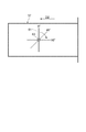
- FIG. 8 is a diagram showing the rotation angle of the propeller unit in the rotary reflection unit
- FIG. 9 is a diagram showing the standing wave state at each rotation angle of the propeller unit shown in FIG.
- the rotation angle at which the propeller unit 61 faces in the direction perpendicular to the microwave conveyance direction D2 is set to 0 °, and the rotation angle increases in the positive direction clockwise in a top view. To do.
- the rotation angle of the propeller unit 61 when the rotation angle of the propeller unit 61 is 0 °, the standing wave shown in FIG. 9A is generated.
- the rotation angle of the propeller unit 61 changes to 45 °, as shown in FIG.
- the microwave reflected from the electromagnetic wave supply unit 34 to the rotation reflection unit 37 and the micro wave reflected by the propeller unit 61 are changed.
- Generation of a standing wave due to the wave is suppressed, and the peak position of the standing wave varies in the waveguide 30.
- the fluctuation of the peak position of the standing wave suppresses uneven drying of the ink in the longitudinal direction of the waveguide bodies 31 and 32.
- the microwave subjected to the reflection termination process in the rotary reflection unit 37 is returned from the rotary reflection unit 37 to the waveguide body 32 again.
- a part of the microwave conveyed to the waveguide main body 32 is absorbed by the ink ejected to the medium M inserted from the insertion port 42, and the ink is dried.
- the microwave that has not been used for drying the ink in the waveguide main body 32 passes through the waveguide main body 32, is bent at the bent portion 33, and then is conveyed to the waveguide main body 31.
- a part of the microwave conveyed to the waveguide main body 31 is absorbed by the ink ejected to the medium M inserted from the insertion port 41, and this ink is dried.
- the microwave that has not been used for drying the ink in the waveguide body 31 passes through the waveguide body 31 and is conveyed to the propagation blocking unit 35.
- the microwave conveyed to the propagation blocking unit 35 is blocked from propagating to the electromagnetic wave supply unit 34 by an isolator 44 attached to the propagation blocking unit 35.
- the solvent discharged from the ink discharged onto the medium M evaporates. Dry while generating. Therefore, by driving the fans 72 and 82, the solvent vapor staying in the waveguide 30 is discharged to the outside of the waveguide 30 to promote the drying of the ink.
- the heaters built in the fans 72 and 82 are energized, and hot air at a predetermined temperature is supplied from the fans 72 and 82 to the inside of the waveguide so that the temperature inside the waveguide 30 becomes 40 ° C. to 60 ° C. To send. Then, the drying of the ink is further promoted by the warm air sent into the waveguide 30.
- Examples 1 to 6 used JV33 manufactured by Mimaki Engineering Co., Ltd.
- Example 1 In Example 1, experiment observation was performed on the blocking state and the back gore state of the medium M when the ink was dried using the inkjet printer 1.
- Blocking refers to a phenomenon in which the vinyl chloride medium constituting the medium M and the protective sheet of the medium adhere to each other, and the back gore refers to a phenomenon in which the protective sheet is distorted and the medium is bent (curled).
- the preheater is a preheater used in a conventional ink jet printer, and is a heater that brings the medium M to a predetermined temperature before the medium M is conveyed to the platen 22.
- the print heater is a print heater used in a conventional ink jet printer, and is a heater that brings the medium M placed on the platen 22 to a predetermined temperature.
- the fan uses a commercially available dryer, and the temperature of the air blown into the waveguide 30 by the fan is such that the outside air heated by the heater is sent into the waveguide 30 by the fan. It is the temperature inside the tube measured inside.
- Table 1 shows the experimental results of Example 1-1
- Table 2 shows the experimental results of Example 1-2
- Table 3 shows the experimental results of Example 1-3. .
- Example 2 In Example 2, the observation of the occurrence of blocking of the media M when the ink was dried using the inkjet printer 1 was experimentally observed.
- the electric power for generating the microwave from the magnetron 43 is changed to 0 W, 300 W, 400 W, 500 W, and 600 W, and the fans 72 and 82 are operated in the high wind mode (air volume: 4.80 m 3 / min) and the low wind mode. (Air volume: 2.37 m 3 / min)
- a warm air of 46 ° C. to 47 ° C. (in-tube temperature) was sent into the waveguide 30 and dried.
- the heating wire is placed on an after heater (50 ° C.) with a built-in heating wire. After passing through the media M, the media left for 1 day was used. And as the reference example 2 compared with Example 2, what was printed with the conventional inkjet printer was used.
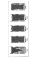
- FIG. 1 A photograph taken of the media dried by this experimental method is shown in FIG.
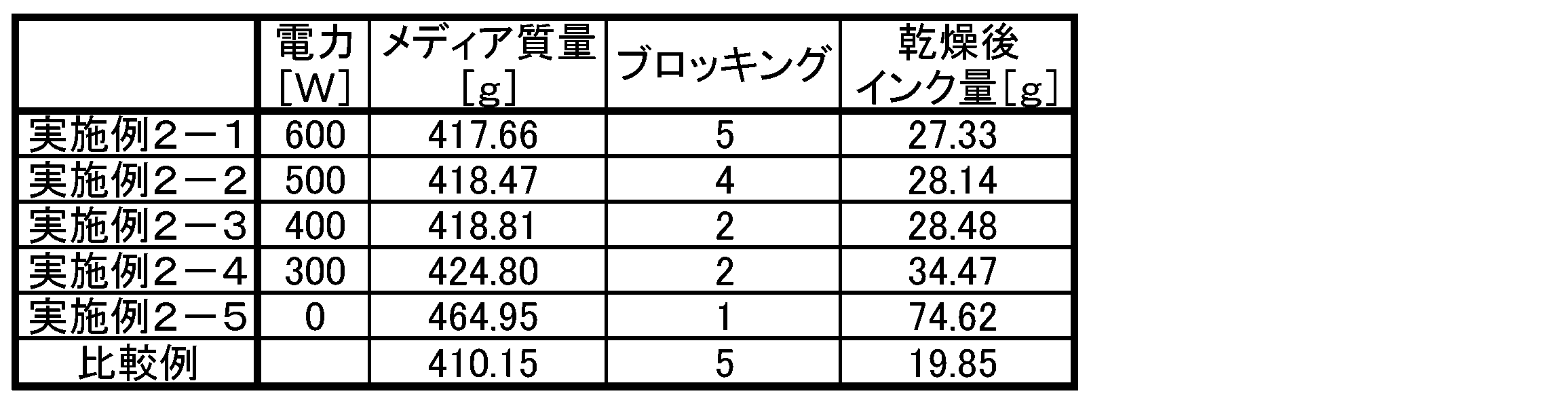
- the occurrence of blocking in Examples 2-1 to 2-5 and Comparative Example 2 is 5 (not occurring), 4 (slightly occurring), 3 (slightly occurring as a whole) in the order of occurrence. It was indicated by a numerical rating of 2 (generally occurring frequently) and 1 (occurring (setback)).
- Table 4 shows the experimental results of Example 2, and FIG. 11 is a graph showing the experimental results of Table 4.
- Example 2 the power of the magnetron 43 is set to 400 W or more to irradiate microwaves, and hot air is sent into the waveguide 30 from the fans 72 and 82, so that after drying. It was found that the amount of ink can be sufficiently reduced. And in Example 2, it turned out that generation
- Example 3 In Example 3, the ink was erased using the ink jet printer 1 and experimentally observed for the eraser scratching property, water scratching property, and alcohol scratching property.
- the electric power for generating the microwave from the magnetron 43 is fixed to 500 W
- the fans 72 and 82 are set in the low wind mode (air volume: 2.37 m 3 / min)
- the temperature is 46 ° C. to 47 ° C. (Temperature) was sent into the waveguide 30 and dried.
- the reference example 3 compared with Example 3, what was printed with the conventional inkjet printer was used.
- Termination Reflection termination by propeller member (4.5V)
- a load of 1.0 kgf was applied to an eraser having a cross section of 7 ⁇ and the printing surface was reciprocated 10 times, and then the degree of ink fading was evaluated.
- numerical values of 10 (high scratching property) to 1 (low scratching property) were expressed as scores in order from the higher scratching property.
- the evaluation method of water rubability was to visually check the color transfer of the ink to the cotton swab and the peeling of the printed surface after impregnating ion-exchanged water into the cotton swab and reciprocating the printed surface 100 times.
- the color transfer to the cotton swab and the peeling of the printing surface were confirmed as “x”, and the color transfer to the cotton swab and the printing surface from peeling were not confirmed as “ ⁇ ”.
- the evaluation method of alcohol rubbing property was that a 0 to 100% alcohol aqueous solution was infiltrated into a cotton swab according to the concentration in 10% increments, the print surface was reciprocated 10 times, and the change of the print surface was visually confirmed. And the alcohol density
- K, M, C, Y, Lm, and Lc indicate ink colors, K is Black, M is Magenta, C is Cyan, Y is Yellow, Lm is Light ⁇ magenta, and Lc is Light cyan. ing.
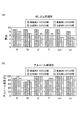
- FIG. 12 (a) shows a comparison between Example 3 and Comparative Example 3 regarding the eraser rubbing property
- FIG. 12 (b) shows a comparison between Example 3 and Comparative Example 3 regarding the alcohol rubbing property.
- Example 3 had the same level of scratching properties as compared with Comparative Example 3, although there were some differences.
- Example 4 In Example 4, the ink was dried using the ink-jet printer 1 and experimentally observed for the contraction of the medium M when the medium M was cut after a predetermined time. In Example 4, after the ink was ejected onto the medium M, the medium M was cut after 1 hour, 3 hours, 6 hours, and 24 hours. And as the reference example 4 compared with Example 4, what was printed with the conventional inkjet printer was used.
- FIG. 13 shows a photograph of the media cut by drying by this experimental method.
- Example 4 almost no shrinkage of the medium M has already been confirmed at the stage when one hour has passed after ink ejection, regardless of the print density.
- the contraction level of cut after 1 hour in Example 4 is substantially the same as the contraction level of cut after 24 hours in Comparative Example 4.
- Example 4 has a faster ink drying speed than Comparative Example 4 and can suppress the shrinkage of the media M in a very short time.
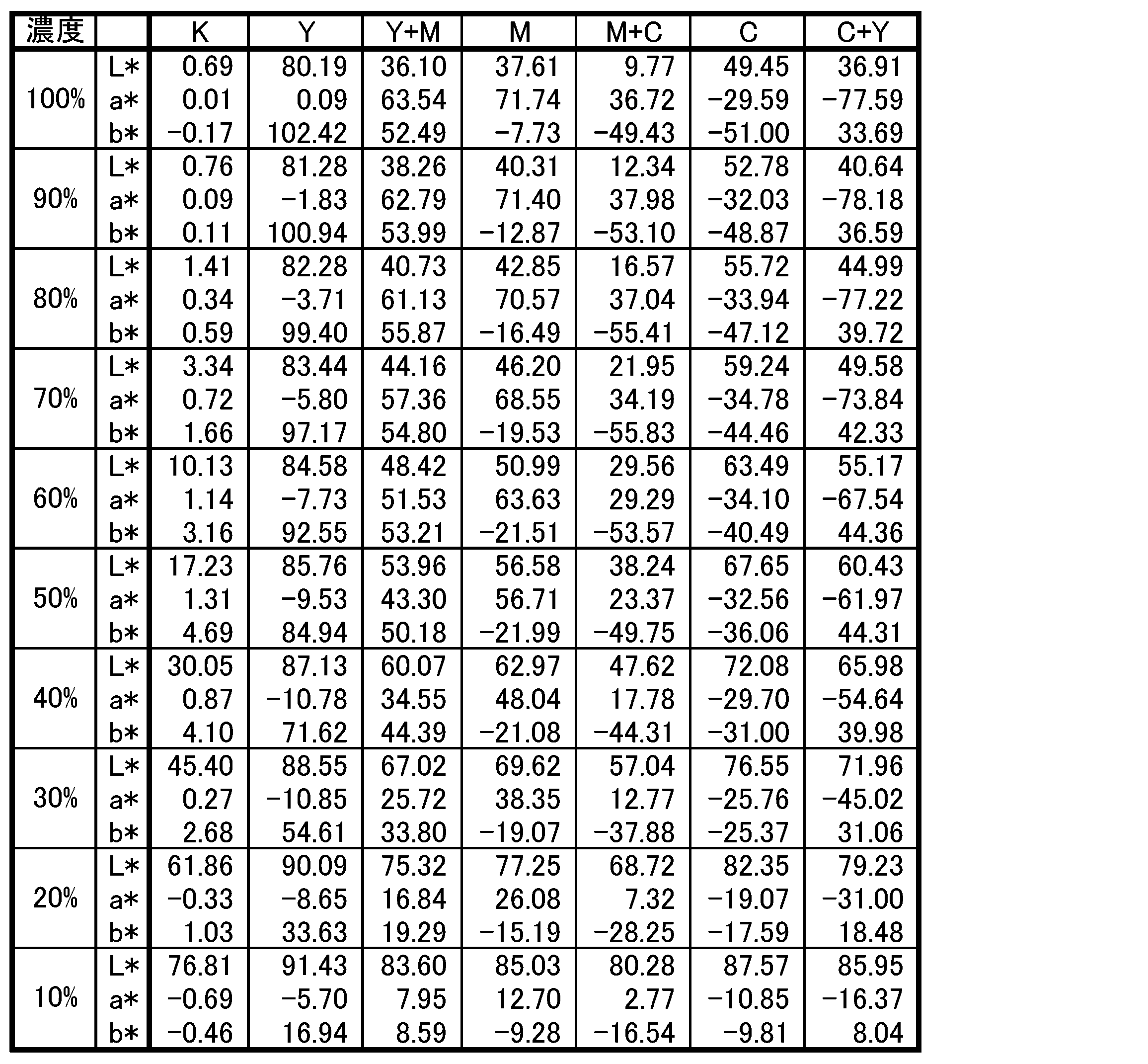
- Example 5 In Example 5, the hue change when the ink was dried using the inkjet printer 1 was observed. In Example 6, prints using inks of each color of K, C, M, Y, C + Y, M + Y, and C + M were used, and prints were made in the range of 10% to 100% in 10% increments. Using. In order to quantify the hue, the L * a * b * color space was used. The L * a * b * color space is defined by the CIE (International Lighting Commission), JIS Z 8729, etc., and the color is determined by the numerical values of the L *, a *, and b * axes. It has become.
- CIE International Lighting Commission
- L * represents lightness (density)
- a * represents reddish on the plus side, greenish on the minus side
- b * represents yellowish on the plus side, and bluish on the minus side.
- Table 7 shows the experimental results of the color space (L *, a *, b *) of Example 5, and Table 8 shows the experimental results of the color space (L *, a *, b *) of Comparative Example 5.
- FIG. 14A shows the color reproduction range of each color represented by a * and b * in Example 5, and
- FIG. 14B shows the color reproduction range of a * and b * in Comparative Example 5. Indicates the color reproduction range of each color.
- FIG. 15 shows a comparison between Example 5 and Comparative Example 5 regarding a * and b * of each color when the printing density is 100%.
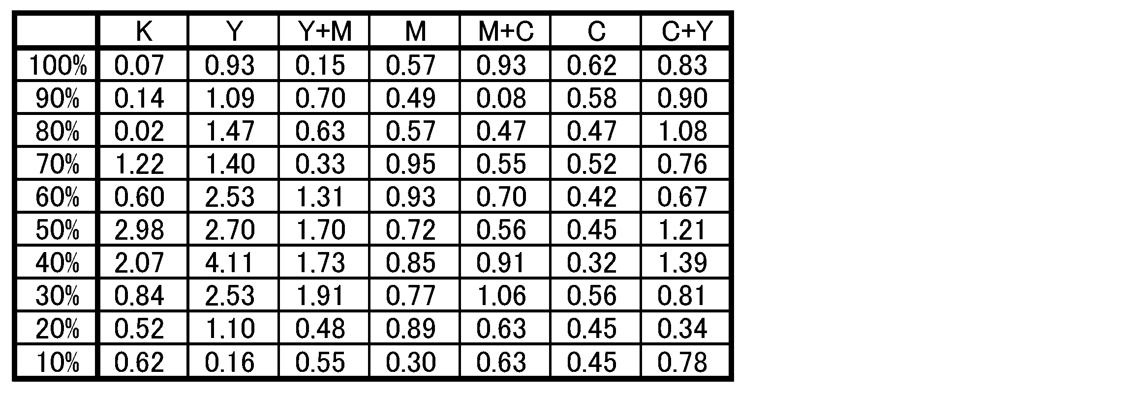
- Table 9 shows the color difference ⁇ E * (ab) in the color space of L * a * b *.
- Example 5 has a hue of almost the same level in the L * a * b * color space, although there is a slight difference compared to Comparative Example 5. I found out.
- Example 6 In Example 6, the change in reflection density from the printing surface when the ink was dried using the inkjet printer 1 was observed. In Example 6, prints using inks of each color of K, C, M, Y, C + Y, M + Y, and C + M were used, and prints were made in the range of 10% to 100% in 10% increments. Using. And as a cited example 6 compared with Example 6, what was printed with the conventional inkjet printer was used. The experimental conditions are the same as in Example 5.
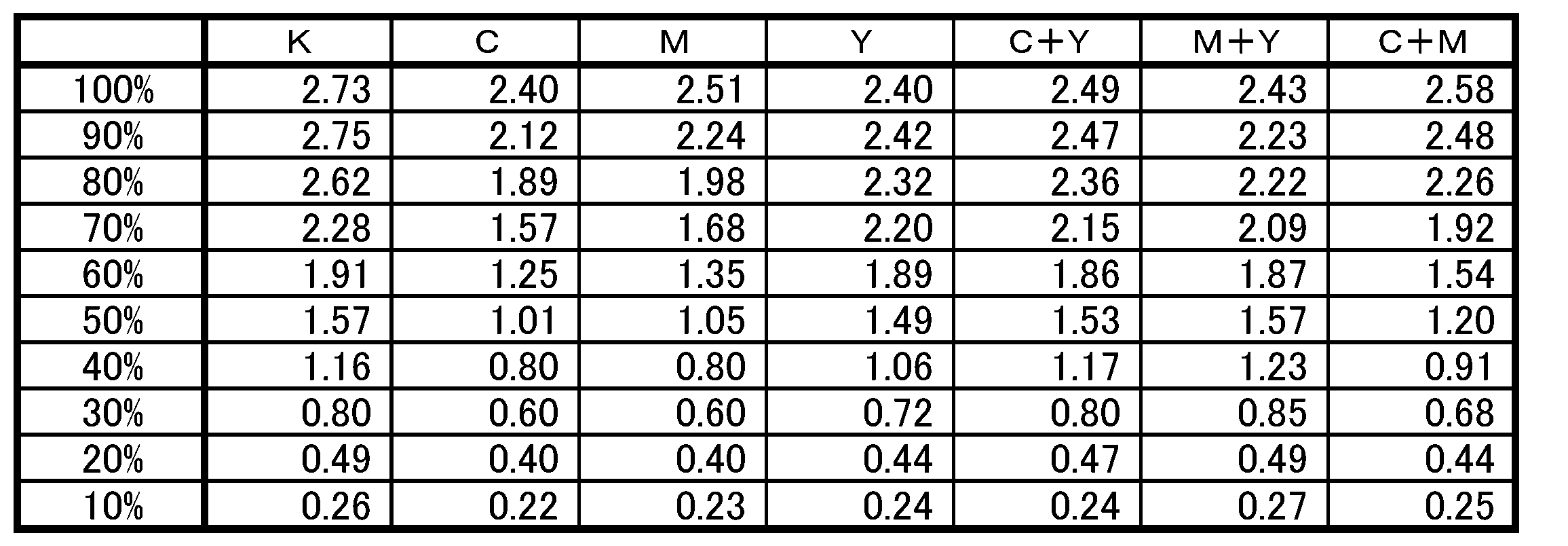
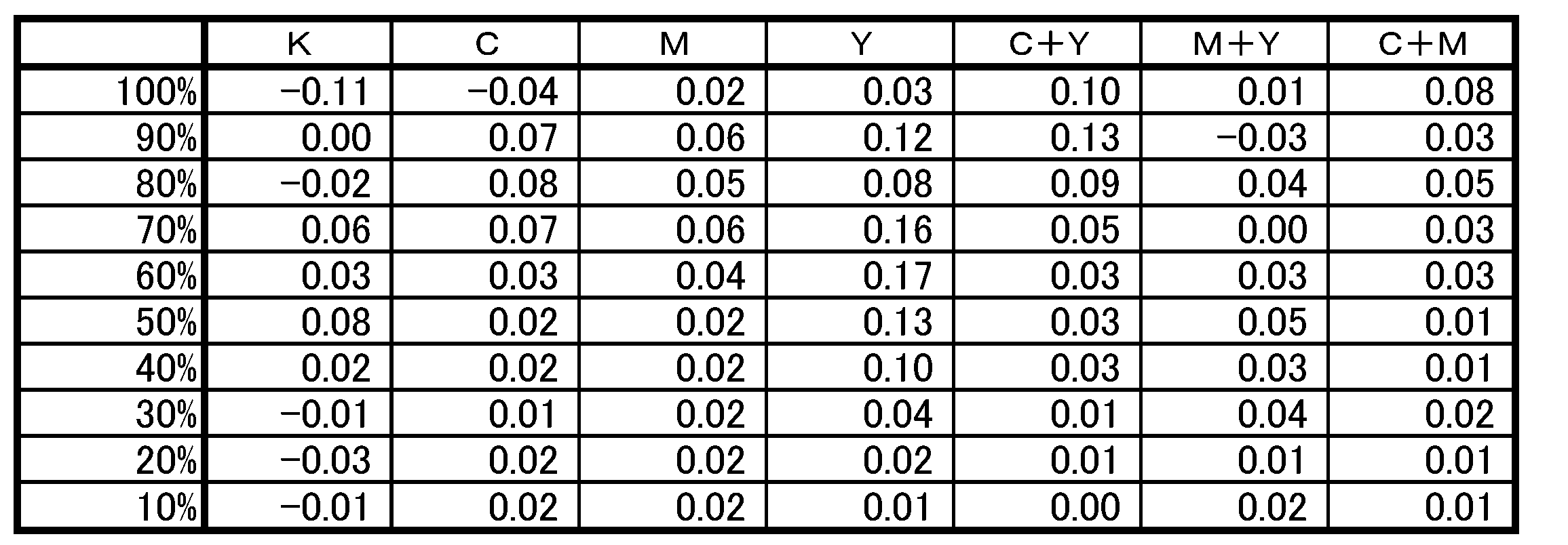
- Table 10 shows the experimental results of the reflection density of Example 6, Table 11 shows the experimental results of the reflection density of Comparative Example 6, and Table 12 shows the difference in the reflective densities of Example 6 and Comparative Example 6.
- Table 12 shows.
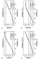
- FIGS. 16 and 17 show the reflection densities of Example 6 and Comparative Example for each color.
- 16 (a) shows the reflection density of K
- FIG. 16 (b) shows the reflection density of C
- FIG. 16 (c) shows the reflection density of M
- FIG. , Y shows the reflection density.
- 17A shows the C + Y reflection density
- FIG. 17B shows the M + Y reflection density
- FIG. 17C shows the C + M reflection density.
- Example 6 had almost no difference in reflection density even when compared with Comparative Example 7.
- Example 7 In Example 7, the dried state when the ink was dried using the inkjet printer 1 was observed. In Example 7, what was printed with ES3 ink and ECO-HS1 ink using JV5 manufactured by Mimaki Engineering Co., Ltd. was used. And as the reference example 7 compared with Example 7, what was printed with the conventional inkjet printer was used.
- the evaluation of blocking is, in order from the lowest degree of occurrence of blocking, 5 (no occurrence), 4 (slight occurrence), 3 (overall occurrence), 2 (overall occurrence), 1 (set-off)
- the numerical value of (occurrence) was expressed as a score.
- dry unevenness is evaluated in the order from the lowest occurrence of dry unevenness to 5 (uniform irradiation), 4 (thick streaks), 3 (thin streaks), 2 (balls are generated) )
- a numerical value of 1 (no back gore) was expressed as a score.
- Table 13 shows the experimental results of Example 7. Table 13 shows the state of occurrence of blocking and drying unevenness for each ink.
- Example 8 In Example 8, the dry state due to the difference in the media feeding speed using the inkjet printer 1 was observed. In Example 8, what was printed using Mimaki Engineering Co., Ltd. product: JV5 and Mimaki Engineering Co., Ltd. product: JV33 was used. And as a reference example 8 compared with the example 8, what was printed with the conventional inkjet printer was used.
- the weight difference of the media when the ink was dried using the inkjet printer 1 was measured, and blocking and drying unevenness were visually confirmed.
- the media weight difference was measured by subtracting the media weight (g) before printing from the media weight (g) after microwave irradiation.
- the evaluation of blocking is, in order from the lowest degree of occurrence of blocking, 5 (no occurrence), 4 (slight occurrence), 3 (overall occurrence), 2 (overall occurrence), 1 (set-off)
- the numerical value of (occurrence) was expressed as a score.
- the dry unevenness was evaluated in order from the lowest dry unevenness generation rate: 5 (uniform irradiation), 4 (thick streaks), 3 (thin streaks), 2 (balls generated), 1 (back gore) (None) was expressed as a score.
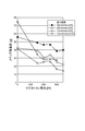
- Tables 14 to 17 and FIG. 18 show the experimental results of Example 8.
- Table 14 shows the relationship between the media feed speed and the microwave irradiation time per unit area
- Table 15 shows the media weight difference
- Table 16 shows the blocking evaluation
- Table 17 Indicates a dry unevenness evaluation.
- FIG. 18 is a diagram showing the relationship between the magnetron power for each feed rate and the media weight difference in the eighth embodiment.
- the microwave irradiation time is increased by slowing down the media feed speed, or the microwave irradiation amount per unit area is increased when printing at high speed. It was found that the dry state became good. In JV5, when the media feed speed is 12 cm / min or less, (2) the microwave irradiation time per unit area is 54 sec (seconds), and (3) the magnetron driving power is 600 W or more, the drying is performed. The condition was found to be good.
- the media feed speed is 12 cm / min and the microwave irradiation amount per unit area is 600 W or more.
- the longer the microwave irradiation time the more heat is transferred from the standing wave through the ink and the drying efficiency increases. It was also found that the microwave irradiation amount per unit area needs to be increased in order to cope with high-speed printing.
- the ink jet printer 1 when ink is ejected to the medium M by the ink jet head 23, the medium M is inserted into the waveguide 30 to which the microwave is supplied by the magnetron 43. Is done. Then, since the microwave supplied by the magnetron 43 propagates through the waveguide 30 and is reflected and terminated by the propeller portion 61 of the propeller member 60 in the rotary reflection portion 37, the reflected microwave again. As a result, the ink discharged onto the medium M is dried.
- the inside of the waveguide 30 is ventilated by the fans 72 and 82 in the ventilation units 38 and 39, so that the solvent vapor of the ink vaporized by the microwave irradiation is forcibly discharged out of the waveguide 30. Therefore, the drying speed of the ink discharged onto the medium M can be improved.
- the rotation direction of the fans 72 and 82 changes the reflection direction of the microwave reflected by the propeller unit 61. Therefore, the microwaves supplied by the magnetron 43 and the microwaves reflected by the propeller unit 61 are changed.
- the generated standing wave fluctuates. Thereby, since the peak position of the standing wave fluctuates in the waveguide 30, uneven drying of the ink ejected to the medium M can be suppressed.
- the ventilation parts 38 and 39 provided with the fans 72 and 82 are disposed at the start and end parts of the waveguide 30, the flow of gas in the waveguide 30 can be made uniform, Ink drying unevenness can be suppressed.
- the drying speed of the ink can be further improved, and the waveguide 30 is set so that the temperature inside the tube becomes 40 ° C. to 60 ° C.
- the waveguide 30 is set so that the temperature inside the tube becomes 40 ° C. to 60 ° C.
- the ink drying speed can be further improved, and the remaining amount of ink can be effectively reduced.
- the fan 72 is provided in the ventilation part 38 disposed between the matching part 36 and the waveguide body 31, and the fan 82 is provided between the waveguide body 32 and the rotary reflection part 37.
- the fan 72 may be provided at any position as long as the insertion ports 41 and 42 of the waveguide main bodies 31 and 32 can be sandwiched at least by the fans 72 and 82.
- the number of fans is not particularly limited. For example, a pair of fans is provided at both ends of the waveguide body 31 and another pair of fans is provided at both ends of the waveguide body 32. It may be.
- the propeller part 61 is made into the flat plate shape which a wing
- the propeller portion 61 may have any shape or rotational direction.
- the microwave which was not reflected by the propeller part 61 in the rotation reflection part 37 demonstrated as what terminates with the short circuit board 90, for example, a microwave is reflected in the back
- the description has been made using the two-stage waveguide, but it may be a one-stage waveguide or a three-stage or more waveguide.
- the present invention can be used as an ink jet printer that ejects ink to form an image or the like on a medium.
- Propeller member (rotary reflection member), 61 ... Propeller part, 62 ... Motor part, 63 ... Rotation output Axis, 70, 80 ... ventilation member, 71, 81 ... air passage, 72, 82 ... fan, 90 ... short circuit plate, 611 ... reflective surface, A ... separation distance, M ... media.
Landscapes
- Physics & Mathematics (AREA)
- Electromagnetism (AREA)
- Engineering & Computer Science (AREA)
- Power Engineering (AREA)
- Health & Medical Sciences (AREA)
- General Health & Medical Sciences (AREA)
- Toxicology (AREA)
- Ink Jet (AREA)
- Accessory Devices And Overall Control Thereof (AREA)
Abstract
Description
実施例1では、インクジェットプリンタ1を用いてインクを乾燥させたときの、メディアMのブロッキング状態及び裏ゴア状態について実験観察した。なお、ブロッキングとは、メディアMを構成する塩ビのメディアとメディアの保護シートとが固着する現象をいい、裏ゴアとは、保護シートが歪んでメディアが湾曲(カール)する現象をいう。
(1)使用インク:Eco-HS1インク(ソルベントインク)
(2)メディア:白塩ビ光沢(中期)
(3)印刷条件:540×1080dpi-6P1L-Bi
300% ベタ印刷
(4)メディアの巻き取りトルク:最大
(5)プレヒーター:35℃
(6)プリントヒーター:35℃
(7)乾燥条件:
〈実施例1-1〉
・マグネトロンによるマイクロ波照射
マグネトロンの電力:500W
・ファンによる送風
送風量:強風モード(4.80m3/min)
風 温:46~47℃(導波管30の管内温度)
〈実施例1-2〉
・マグネトロンによるマイクロ波照射
マグネトロンの電力:500W
・ファンによる送風
送風量:強風モード(4.80m3/min)
弱風モード(2.37m3/min)
風 温:温風(ヒーターON:46~47℃)
冷風(ヒーターOFF:室温)
〈実施例1-3〉
・マグネトロンによるマイクロ波照射
マグネトロンの電力:600W
・ファンによる送風
送風量:強風モード(4.80m3/min)
弱風モード(2.37m3/min)
風 温:温風(ヒーターON:46~47℃)
冷風(ヒーターOFF:室温)
(8)終端:プロペラ部材による反射終端(4.5V)
である。



実施例2では、インクジェットプリンタ1を用いてインクを乾燥させたときの、メディアMのブロッキングの発生状態について実験観察した。実施例2では、マグネトロン43からマイクロ波を発生させる電力を0W、300W、400W、500W、600Wと変化させるとともに、ファン72,82を強風モード(風量:4.80m3/min)と弱風モード(風量:2.37m3/min)とに分けて、46℃~47℃(管内温度)の温風を導波管30内に送り込んで乾燥させたものを用いた。そして、実施例2の比較例2として、マグネトロン43及びファン72,82を作動させずに、メディアMにインクを吐出させた後工程において、電熱線が内蔵されたアフターヒーター(50℃)上にメディアMを通過させた後、1日放置したものを用いた。そして、実施例2と対比する引用例2として、従来のインクジェットプリンタにより印刷したものを用いた。
(1)使用インク:Eco-HS1インク(ソルベントインク)
(2)メディア:白塩ビ光沢(中期)
(3)印刷条件:540×1080dpi-6P1L-Bi
300% ベタ印刷
(4)メディアの巻き取りトルク:最大
(5)プレヒーター:35℃
(6)プリントヒーター:35℃
(7)プロペラ部の回転速度:15.6rpm
(8)乾燥条件:
〈実施例2-1〉
・マグネトロンによるマイクロ波照射
マグネトロンの電力:600W
・ファンによる送風
送風量:弱風モード(2.37m3/min)
風 温:温風(ヒーターON:46~47℃)
〈実施例2-2〉
・マグネトロンによるマイクロ波照射
マグネトロンの電力:500W
・ファンによる送風
送風量:弱風モード(2.37m3/min)
風 温:温風(ヒーターON:46~47℃)
〈実施例2-3〉
・マグネトロンによるマイクロ波照射
マグネトロンの電力:400W
・ファンによる送風
送風量:弱風モード(2.37m3/min)
風 温:温風(ヒーターON:46~47℃)
〈実施例2-4〉
・マグネトロンによるマイクロ波照射
マグネトロンの電力:300W
・ファンによる送風
送風量:弱風モード(2.37m3/min)
風 温:温風(ヒーターON:46~47℃)
〈実施例2-5〉
・マグネトロンによるマイクロ波照射
マグネトロンの電力:0W
・ファンによる送風
送風量:弱風モード(2.37m3/min)
風 温:温風(ヒーターON:46~47℃)
〈比較例2〉
・アフターヒーター+自然乾燥(24時間放置)
アフターヒーターの温度:50℃
(9)終端:プロペラ部材による反射終端(4.5V)
である。
実施例3では、インクジェットプリンタ1を用いてインクを乾燥させたときの、消しゴム擦過性、水擦過性、アルコール擦過性について実験観察した。実施例3では、マグネトロン43からマイクロ波を発生させる電力を500Wに固定し、ファン72,82を弱風モード(風量:2.37m3/min)に設定して、46℃~47℃(管内温度)の温風を導波管30内に送り込んで乾燥させたものを用いた。そして、実施例3と対比する引用例3として、従来のインクジェットプリンタにより印刷したものを用いた。
(1)使用インク:Eco-HS1インク(ソルベントインク)
(2)メディア:白塩ビ光沢(中期)
(3)印刷条件:540×1080dpi-6P1L-Bi
100%、20% ベタ印字
(4)メディアの巻き取りトルク:最大
(5)プレヒーター:35℃
(6)プリントヒーター:35℃
(7)印刷濃度、乾燥条件:
〈実施例3〉
・マグネトロンによるマイクロ波照射
マグネトロンの電力:500W
・ファンによる送風
送風量:弱風モード(2.37m3/min)
風 温:温風(ヒーターON:46~47℃)
〈比較例3〉
・アフターヒーター+自然乾燥(24時間放置)
アフターヒーターの温度:50℃
である。
消しゴム擦過性の評価方法は、断面7φの消しゴムに1.0kgfの荷重を加えて印刷面を10往復させた後、インクのかすれ度合いを評価した。そして、この評価は、擦過性の高い方から順に、10(擦過性が高い)~1(擦過性が低い)の数値を評点として表した。


実施例4では、インクジェットプリンタ1を用いてインクを乾燥させて、所定時間後にメディアMをカットとしたときのメディアMの収縮について実験観察した。実施例4では、インクをメディアMに吐出してから、1時間後、3時間後、6時間後、24時間後にメディアMをカットしたものを用いた。そして、実施例4と対比する引用例4として、従来のインクジェットプリンタにより印刷したものを用いた。
(1)使用インク:Eco-HS1インク(ソルベントインク)
(2)メディア:白塩ビ光沢(中期)
(3)印刷条件:540×1080dpi-6P1L-Bi
・300%濃度:C,M,Yを各100%濃度で印刷
・200%濃度:M,Cを各100%濃度で印刷
(4)メディアの巻き取りトルク:最大
(5)プレヒーター:35℃
(6)プリントヒーター:35℃
(7)乾燥条件:
〈実施例4〉
・マグネトロンによるマイクロ波照射
マグネトロンの電力:500W
・ファンによる送風
送風量:弱風モード(2.37m3/min)
風 温:温風(ヒーターON:46~47℃)
〈比較例4〉
・アフターヒーター+自然乾燥(24時間放置)
アフターヒーターの温度:50℃
(8)終端:プロペラ部材による反射終端(4.5V)
である。
実施例5では、インクジェットプリンタ1を用いてインクを乾燥させたときの、色相変化について観察した。実施例6では、K,C,M,Y,C+Y,M+Y,C+Mの各色のインクで印刷したものを用い、それぞれ、印刷濃度が10%刻みで10%~100%の範囲で印刷したものを用いた。そして、色相を定量化するために、L*a*b*色空間を用いた。L*a*b*色空間は、CIE(国際照明委員会)やJIS Z 8729などで定められているもので、L*軸、a*軸、b*軸の各軸の数値によって色が定量化されている。L*は明度(濃度)を表し、a*はプラス側で赤味、マイナス側で緑味を表し、b*はプラス側で黄味、マイナス側で青みを表す。そして、実施例5と対比する引用例5として、従来のインクジェットプリンタにより印刷したものを用いた。
(1)使用インク:Eco-HS1インク(ソルベントインク)
(2)メディア:白塩ビ光沢(中期)
(3)印刷条件:540×1080dpi-6P1L-Bi
100% ベタ印刷
(4)メディアの巻き取りトルク:最大
(5)プレヒーター:35℃
(6)プリントヒーター:35℃
(7)乾燥条件:
〈実施例5〉
・マグネトロンによるマイクロ波照射
マグネトロンの電力:600W
・ファンによる送風
送風量:弱風モード(2.37m3/min)
風 温:温風(ヒーターON:46~47℃)
〈比較例5〉
・アフターヒーター+自然乾燥(24時間放置)
アフターヒーターの温度:50℃
(8)終端:プロペラ部材による反射終端(4.5V)
である。

実施例6では、インクジェットプリンタ1を用いてインクを乾燥させたときの、印刷面からの反射濃度変化について観察した。実施例6では、K,C,M,Y,C+Y,M+Y,C+Mの各色のインクで印刷したものを用い、それぞれ、印刷濃度が10%刻みで10%~100%の範囲で印刷したものを用いた。そして、実施例6と対比する引用例6として、従来のインクジェットプリンタにより印刷したものを用いた。なお、実験条件は、実施例5と同一である。

実施例7では、インクジェットプリンタ1を用いてインクを乾燥させたときの、乾燥状態について観察した。実施例7では、株式会社ミマキエンジニアリング社製:JV5を使用して、ES3インク、ECO-HS1インクで印刷したものを用いた。そして、実施例7と対比する引用例7として、従来のインクジェットプリンタにより印刷したものを用いた。
(1)使用インク:ES3インク、Eco-HS1インク(ソルベントインク)
(2)メディア:白塩ビ光沢(中期)
(3)印刷条件:720×1080dpi-Hi-Bi
300% ベタ印刷
(4)メディアの巻き取りトルク:最大
(5)プレヒーター:50℃
(6)プリントヒーター:40℃
(7)乾燥条件:
〈実施例7〉
・マグネトロンによるマイクロ波照射
マグネトロンの電力:700W
・ファンによる送風
送風量:弱風モード(2.37m3/min)
風 温:温風(ヒーターON:46~47℃)
・プロペラ部材の回転速度:3rpm
〈比較例7〉
・アフターヒーター+自然乾燥(24時間放置)
アフターヒーターの温度:50℃
(8)終端:プロペラ部材による反射終端(4.5V)
である。

実施例8では、インクジェットプリンタ1を用いたメディア送り速度の違いによる乾燥状態について観察した。実施例8では、株式会社ミマキエンジニアリング社製:JV5、株式会社ミマキエンジニアリング社製:JV33を使用して印刷したものを用いた。そして、実施例8と対比する引用例8として、従来のインクジェットプリンタにより印刷したものを用いた。
(1)使用インク:Eco-HS1インク(ソルベントインク)
(2)メディア:白塩ビ光沢(中期)
(3)印刷条件:540×1080dpi-6,12,24-Hi-Bi
300% ベタ印刷
(4)メディアの巻き取りトルク:最大
(5)プレヒーター:35℃
(6)プリントヒーター:35℃
(7)乾燥条件:
〈実施例8-1〉
・マグネトロンによるマイクロ波照射
マグネトロンの電力:0W
・ファンによる送風
送風量:弱風モード(2.37m3/min)
風 温:温風(ヒーターON:46~47℃)
〈実施例8-2〉
・マグネトロンによるマイクロ波照射
マグネトロンの電力:300W
・ファンによる送風
送風量:弱風モード(2.37m3/min)
風 温:温風(ヒーターON:46~47℃)
〈実施例8-3〉
・マグネトロンによるマイクロ波照射
マグネトロンの電力:400W
・ファンによる送風
送風量:弱風モード(2.37m3/min)
風 温:温風(ヒーターON:46~47℃)
〈実施例8-4〉
・マグネトロンによるマイクロ波照射
マグネトロンの電力:500W
・ファンによる送風
送風量:弱風モード(2.37m3/min)
風 温:温風(ヒーターON:46~47℃)
〈実施例8-5〉
・マグネトロンによるマイクロ波照射
マグネトロンの電力:600W
・ファンによる送風
送風量:弱風モード(2.37m3/min)
風 温:温風(ヒーターON:46~47℃)
〈実施例8-6〉
・マグネトロンによるマイクロ波照射
マグネトロンの電力:700W
・ファンによる送風
送風量:弱風モード(2.37m3/min)
風 温:温風(ヒーターON:46~47℃)
〈比較例8〉
・アフターヒーター+自然乾燥(24時間放置)
アフターヒーターの温度:50℃
(8)終端:プロペラ部材による反射終端(4.5V)
プロペラ部材の回転速度:3rpm
である。



Claims (5)
- メディアに向けてインクを吐出する吐出手段と、
前記吐出手段によりインクが吐出されたメディアが内部に挿通される導波管と、
前記導波管の始端部に設けられて、前記導波管に電磁波を供給する電磁波供給手段と、
前記導波管の終端部に設けられて、前記電磁波供給手段により供給された電磁波を回転して反射する回転反射部材と、
前記導波管内を換気する換気手段と、
を有する、インクジェットプリンタ。 - 前記換気手段は、前記導波管の始端部及び終端部に設けられる、請求項1に記載のインクジェットプリンタ。
- 前記換気手段は、前記導波管内に温風を送る、請求項1又は2に記載のインクジェットプリンタ。
- 前記温風の温度は、40℃~60℃である、請求項3に記載のインクジェットプリンタ。
- 前記電磁波供給手段は、400W以上の電力により発生する電磁波を前記導波管に供給する、請求項1~4の何れか1項に記載のインクジェットプリンタ。
Priority Applications (4)
| Application Number | Priority Date | Filing Date | Title |
|---|---|---|---|
| CN2009801152047A CN102015309B (zh) | 2008-11-28 | 2009-11-20 | 喷墨打印机 |
| KR1020107023416A KR101248968B1 (ko) | 2008-11-28 | 2009-11-20 | 잉크젯 프린터 |
| EP09829044.8A EP2279866B1 (en) | 2008-11-28 | 2009-11-20 | Inkjet printer |
| US12/900,503 US8366261B2 (en) | 2008-11-28 | 2010-10-08 | Inkjet printer |
Applications Claiming Priority (2)
| Application Number | Priority Date | Filing Date | Title |
|---|---|---|---|
| JP2008-304825 | 2008-11-28 | ||
| JP2008304825A JP4891978B2 (ja) | 2008-11-28 | 2008-11-28 | インクジェットプリンタ |
Related Child Applications (1)
| Application Number | Title | Priority Date | Filing Date |
|---|---|---|---|
| US12/900,503 Continuation US8366261B2 (en) | 2008-11-28 | 2010-10-08 | Inkjet printer |
Publications (1)
| Publication Number | Publication Date |
|---|---|
| WO2010061796A1 true WO2010061796A1 (ja) | 2010-06-03 |
Family
ID=42225672
Family Applications (1)
| Application Number | Title | Priority Date | Filing Date |
|---|---|---|---|
| PCT/JP2009/069727 Ceased WO2010061796A1 (ja) | 2008-11-28 | 2009-11-20 | インクジェットプリンタ |
Country Status (6)
| Country | Link |
|---|---|
| US (1) | US8366261B2 (ja) |
| EP (1) | EP2279866B1 (ja) |
| JP (1) | JP4891978B2 (ja) |
| KR (1) | KR101248968B1 (ja) |
| CN (1) | CN102015309B (ja) |
| WO (1) | WO2010061796A1 (ja) |
Families Citing this family (7)
| Publication number | Priority date | Publication date | Assignee | Title |
|---|---|---|---|---|
| US8780147B2 (en) * | 2011-09-27 | 2014-07-15 | Eastman Kodak Company | Large-particle semiporous-paper inkjet printer |
| US8690312B2 (en) * | 2011-09-27 | 2014-04-08 | Eastman Kodak Company | Inkjet printer using large particles |
| CN103448382B (zh) * | 2013-07-02 | 2016-01-13 | 苏州威仕薄膜科技有限公司 | 一种具有热吹风装置的卷绕架的大幅面打印机 |
| CN103956407B (zh) * | 2014-04-23 | 2017-06-06 | 中国科学院物理研究所 | 制备钙钛矿基薄膜太阳电池的方法及喷墨打印机 |
| US10052901B1 (en) * | 2017-02-20 | 2018-08-21 | Ricoh Company, Ltd. | Multi-pass microwave dryers for printing systems |
| JP2018158508A (ja) * | 2017-03-23 | 2018-10-11 | 株式会社Screenホールディングス | 印刷装置および印刷方法 |
| JP7413409B2 (ja) * | 2019-12-25 | 2024-01-15 | 富士フイルム株式会社 | 画像記録方法 |
Citations (5)
| Publication number | Priority date | Publication date | Assignee | Title |
|---|---|---|---|---|
| JPS5711496A (en) * | 1980-05-23 | 1982-01-21 | Yungu Gmbh | Microwave heater |
| JPH07314661A (ja) * | 1994-05-27 | 1995-12-05 | Canon Inc | インクジェット記録方法及び記録装置 |
| JP2003022890A (ja) | 2001-04-30 | 2003-01-24 | Hewlett Packard Co <Hp> | 乾燥装置及び乾燥方法、並びにイメージング装置 |
| JP2004334176A (ja) * | 2003-05-06 | 2004-11-25 | Nexpress Solutions Llc | マイクロ波装置内で被印刷物をハンドリングするための装置および方法 |
| JP2007083566A (ja) * | 2005-09-22 | 2007-04-05 | Konica Minolta Holdings Inc | 画像形成装置 |
Family Cites Families (10)
| Publication number | Priority date | Publication date | Assignee | Title |
|---|---|---|---|---|
| GB1050493A (ja) * | ||||
| US3584389A (en) * | 1969-02-03 | 1971-06-15 | Hirst Microwave Heating Ltd | Print drying |
| US4629849A (en) * | 1984-06-28 | 1986-12-16 | Ngk Insulators Ltd. | Microwave heating device having a rotary reflector means in a heating chamber |
| US5220346A (en) * | 1992-02-03 | 1993-06-15 | Xerox Corporation | Printing processes with microwave drying |
| US5422463A (en) * | 1993-11-30 | 1995-06-06 | Xerox Corporation | Dummy load for a microwave dryer |
| JPH10112385A (ja) * | 1996-10-03 | 1998-04-28 | Toshiba Mechatronics Kk | マイクロ波加熱装置 |
| JP2001301131A (ja) * | 2000-04-19 | 2001-10-30 | Sharp Corp | インクジェット記録装置 |
| US6663239B2 (en) * | 2001-10-31 | 2003-12-16 | Hewlett-Packard Development Company, L.P. | Microwave applicator for inkjet printer |
| US6938358B2 (en) * | 2002-02-15 | 2005-09-06 | International Business Machines Corporation | Method and apparatus for electromagnetic drying of printed media |
| JP4855052B2 (ja) * | 2005-11-21 | 2012-01-18 | 富士フイルム株式会社 | インク組成物、インクジェット記録方法、印刷物、平版印刷版の製造方法及び平版印刷版 |
-
2008
- 2008-11-28 JP JP2008304825A patent/JP4891978B2/ja not_active Expired - Fee Related
-
2009
- 2009-11-20 WO PCT/JP2009/069727 patent/WO2010061796A1/ja not_active Ceased
- 2009-11-20 CN CN2009801152047A patent/CN102015309B/zh not_active Expired - Fee Related
- 2009-11-20 KR KR1020107023416A patent/KR101248968B1/ko not_active Expired - Fee Related
- 2009-11-20 EP EP09829044.8A patent/EP2279866B1/en not_active Not-in-force
-
2010
- 2010-10-08 US US12/900,503 patent/US8366261B2/en not_active Expired - Fee Related
Patent Citations (5)
| Publication number | Priority date | Publication date | Assignee | Title |
|---|---|---|---|---|
| JPS5711496A (en) * | 1980-05-23 | 1982-01-21 | Yungu Gmbh | Microwave heater |
| JPH07314661A (ja) * | 1994-05-27 | 1995-12-05 | Canon Inc | インクジェット記録方法及び記録装置 |
| JP2003022890A (ja) | 2001-04-30 | 2003-01-24 | Hewlett Packard Co <Hp> | 乾燥装置及び乾燥方法、並びにイメージング装置 |
| JP2004334176A (ja) * | 2003-05-06 | 2004-11-25 | Nexpress Solutions Llc | マイクロ波装置内で被印刷物をハンドリングするための装置および方法 |
| JP2007083566A (ja) * | 2005-09-22 | 2007-04-05 | Konica Minolta Holdings Inc | 画像形成装置 |
Non-Patent Citations (1)
| Title |
|---|
| See also references of EP2279866A4 * |
Also Published As
| Publication number | Publication date |
|---|---|
| KR101248968B1 (ko) | 2013-04-01 |
| CN102015309B (zh) | 2013-06-05 |
| EP2279866A4 (en) | 2014-05-21 |
| KR20100134051A (ko) | 2010-12-22 |
| JP4891978B2 (ja) | 2012-03-07 |
| EP2279866B1 (en) | 2015-07-29 |
| US8366261B2 (en) | 2013-02-05 |
| JP2010125781A (ja) | 2010-06-10 |
| CN102015309A (zh) | 2011-04-13 |
| US20110074864A1 (en) | 2011-03-31 |
| EP2279866A1 (en) | 2011-02-02 |
Similar Documents
| Publication | Publication Date | Title |
|---|---|---|
| JP4891978B2 (ja) | インクジェットプリンタ | |
| JP3276278B2 (ja) | 記録液定着装置およびこれを具備する液体噴射記録装置 | |
| US8434849B2 (en) | Printing apparatus to dry sheets on which ink is applied | |
| JPH06210847A (ja) | インクジェット・プリンタ | |
| US8282204B2 (en) | Printing apparatus | |
| JP7642043B2 (ja) | 記録装置及び記録方法 | |
| JPH06210839A (ja) | インクジェット・プリンタ及びヒータ・スクリーン | |
| US12030303B2 (en) | Printing apparatus for performing printing to an elongated print medium | |
| US10442213B2 (en) | Drying device, liquid discharge apparatus, and treatment liquid applicator | |
| JP2017114001A (ja) | 乾燥装置、造形装置、及び乾燥方法 | |
| JP2011068485A (ja) | インクジェット印刷装置 | |
| JP2024020527A (ja) | 記録装置及び制御方法 | |
| JP2010208100A (ja) | 画像形成装置 | |
| CN101612829B (zh) | 喷墨打印机及打印方法 | |
| JP2011051122A (ja) | 印刷装置 | |
| JP2015168116A (ja) | 乾燥装置、画像形成装置 | |
| JP2005161814A (ja) | インクジェット画像形成装置 | |
| JP2011068479A (ja) | インクジェットプリンタのデカールユニット及びインクジェットプリンタ | |
| JP2018171722A (ja) | 画像記録装置 | |
| WO2010041631A1 (ja) | インクジェットプリンタ | |
| JP5054651B2 (ja) | インクジェットプリンタ | |
| JP2017222135A (ja) | 画像記録装置 | |
| JP4914416B2 (ja) | インクジェットプリンタ | |
| US20250360736A1 (en) | Printing apparatus | |
| JP2017222134A (ja) | 画像記録装置および画像記録方法 |
Legal Events
| Date | Code | Title | Description |
|---|---|---|---|
| WWE | Wipo information: entry into national phase |
Ref document number: 200980115204.7 Country of ref document: CN |
|
| 121 | Ep: the epo has been informed by wipo that ep was designated in this application |
Ref document number: 09829044 Country of ref document: EP Kind code of ref document: A1 |
|
| ENP | Entry into the national phase |
Ref document number: 20107023416 Country of ref document: KR Kind code of ref document: A |
|
| WWE | Wipo information: entry into national phase |
Ref document number: 2009829044 Country of ref document: EP |
|
| NENP | Non-entry into the national phase |
Ref country code: DE |